EP3062676B1 - Oberflächenreinigungsvorrichtung - Google Patents
Oberflächenreinigungsvorrichtung Download PDFInfo
- Publication number
- EP3062676B1 EP3062676B1 EP14706662.5A EP14706662A EP3062676B1 EP 3062676 B1 EP3062676 B1 EP 3062676B1 EP 14706662 A EP14706662 A EP 14706662A EP 3062676 B1 EP3062676 B1 EP 3062676B1
- Authority
- EP
- European Patent Office
- Prior art keywords
- storage device
- cleaning apparatus
- cable storage
- surface cleaning
- suction
- Prior art date
- Legal status (The legal status is an assumption and is not a legal conclusion. Google has not performed a legal analysis and makes no representation as to the accuracy of the status listed.)
- Active
Links
- 238000004140 cleaning Methods 0.000 title claims description 28
- 239000012530 fluid Substances 0.000 claims description 40
- 230000001419 dependent effect Effects 0.000 claims description 3
- 238000001816 cooling Methods 0.000 description 3
- 239000000463 material Substances 0.000 description 3
- 238000011045 prefiltration Methods 0.000 description 3
- 238000011144 upstream manufacturing Methods 0.000 description 2
- 239000004676 acrylonitrile butadiene styrene Substances 0.000 description 1
- 230000004913 activation Effects 0.000 description 1
- 230000009286 beneficial effect Effects 0.000 description 1
- 230000015572 biosynthetic process Effects 0.000 description 1
- 230000000694 effects Effects 0.000 description 1
- 230000003993 interaction Effects 0.000 description 1
- 238000013021 overheating Methods 0.000 description 1
- 239000004033 plastic Substances 0.000 description 1
- 229920003023 plastic Polymers 0.000 description 1
- 239000004417 polycarbonate Substances 0.000 description 1
- 229920000515 polycarbonate Polymers 0.000 description 1
- 239000012780 transparent material Substances 0.000 description 1
- 230000000007 visual effect Effects 0.000 description 1
- 238000004804 winding Methods 0.000 description 1
Images


Classifications
-
- A—HUMAN NECESSITIES
- A47—FURNITURE; DOMESTIC ARTICLES OR APPLIANCES; COFFEE MILLS; SPICE MILLS; SUCTION CLEANERS IN GENERAL
- A47L—DOMESTIC WASHING OR CLEANING; SUCTION CLEANERS IN GENERAL
- A47L5/00—Structural features of suction cleaners
- A47L5/12—Structural features of suction cleaners with power-driven air-pumps or air-compressors, e.g. driven by motor vehicle engine vacuum
- A47L5/22—Structural features of suction cleaners with power-driven air-pumps or air-compressors, e.g. driven by motor vehicle engine vacuum with rotary fans
- A47L5/36—Suction cleaners with hose between nozzle and casing; Suction cleaners for fixing on staircases; Suction cleaners for carrying on the back
- A47L5/362—Suction cleaners with hose between nozzle and casing; Suction cleaners for fixing on staircases; Suction cleaners for carrying on the back of the horizontal type, e.g. canister or sledge type
-
- A—HUMAN NECESSITIES
- A47—FURNITURE; DOMESTIC ARTICLES OR APPLIANCES; COFFEE MILLS; SPICE MILLS; SUCTION CLEANERS IN GENERAL
- A47L—DOMESTIC WASHING OR CLEANING; SUCTION CLEANERS IN GENERAL
- A47L9/00—Details or accessories of suction cleaners, e.g. mechanical means for controlling the suction or for effecting pulsating action; Storing devices specially adapted to suction cleaners or parts thereof; Carrying-vehicles specially adapted for suction cleaners
- A47L9/10—Filters; Dust separators; Dust removal; Automatic exchange of filters
- A47L9/16—Arrangement or disposition of cyclones or other devices with centrifugal action
- A47L9/165—Construction of inlets
-
- A—HUMAN NECESSITIES
- A47—FURNITURE; DOMESTIC ARTICLES OR APPLIANCES; COFFEE MILLS; SPICE MILLS; SUCTION CLEANERS IN GENERAL
- A47L—DOMESTIC WASHING OR CLEANING; SUCTION CLEANERS IN GENERAL
- A47L5/00—Structural features of suction cleaners
- A47L5/12—Structural features of suction cleaners with power-driven air-pumps or air-compressors, e.g. driven by motor vehicle engine vacuum
- A47L5/22—Structural features of suction cleaners with power-driven air-pumps or air-compressors, e.g. driven by motor vehicle engine vacuum with rotary fans
- A47L5/36—Suction cleaners with hose between nozzle and casing; Suction cleaners for fixing on staircases; Suction cleaners for carrying on the back
-
- A—HUMAN NECESSITIES
- A47—FURNITURE; DOMESTIC ARTICLES OR APPLIANCES; COFFEE MILLS; SPICE MILLS; SUCTION CLEANERS IN GENERAL
- A47L—DOMESTIC WASHING OR CLEANING; SUCTION CLEANERS IN GENERAL
- A47L9/00—Details or accessories of suction cleaners, e.g. mechanical means for controlling the suction or for effecting pulsating action; Storing devices specially adapted to suction cleaners or parts thereof; Carrying-vehicles specially adapted for suction cleaners
-
- A—HUMAN NECESSITIES
- A47—FURNITURE; DOMESTIC ARTICLES OR APPLIANCES; COFFEE MILLS; SPICE MILLS; SUCTION CLEANERS IN GENERAL
- A47L—DOMESTIC WASHING OR CLEANING; SUCTION CLEANERS IN GENERAL
- A47L9/00—Details or accessories of suction cleaners, e.g. mechanical means for controlling the suction or for effecting pulsating action; Storing devices specially adapted to suction cleaners or parts thereof; Carrying-vehicles specially adapted for suction cleaners
- A47L9/009—Carrying-vehicles; Arrangements of trollies or wheels; Means for avoiding mechanical obstacles
-
- A—HUMAN NECESSITIES
- A47—FURNITURE; DOMESTIC ARTICLES OR APPLIANCES; COFFEE MILLS; SPICE MILLS; SUCTION CLEANERS IN GENERAL
- A47L—DOMESTIC WASHING OR CLEANING; SUCTION CLEANERS IN GENERAL
- A47L9/00—Details or accessories of suction cleaners, e.g. mechanical means for controlling the suction or for effecting pulsating action; Storing devices specially adapted to suction cleaners or parts thereof; Carrying-vehicles specially adapted for suction cleaners
- A47L9/10—Filters; Dust separators; Dust removal; Automatic exchange of filters
- A47L9/16—Arrangement or disposition of cyclones or other devices with centrifugal action
- A47L9/1608—Cyclonic chamber constructions
-
- A—HUMAN NECESSITIES
- A47—FURNITURE; DOMESTIC ARTICLES OR APPLIANCES; COFFEE MILLS; SPICE MILLS; SUCTION CLEANERS IN GENERAL
- A47L—DOMESTIC WASHING OR CLEANING; SUCTION CLEANERS IN GENERAL
- A47L9/00—Details or accessories of suction cleaners, e.g. mechanical means for controlling the suction or for effecting pulsating action; Storing devices specially adapted to suction cleaners or parts thereof; Carrying-vehicles specially adapted for suction cleaners
- A47L9/10—Filters; Dust separators; Dust removal; Automatic exchange of filters
- A47L9/16—Arrangement or disposition of cyclones or other devices with centrifugal action
- A47L9/1616—Multiple arrangement thereof
-
- A—HUMAN NECESSITIES
- A47—FURNITURE; DOMESTIC ARTICLES OR APPLIANCES; COFFEE MILLS; SPICE MILLS; SUCTION CLEANERS IN GENERAL
- A47L—DOMESTIC WASHING OR CLEANING; SUCTION CLEANERS IN GENERAL
- A47L9/00—Details or accessories of suction cleaners, e.g. mechanical means for controlling the suction or for effecting pulsating action; Storing devices specially adapted to suction cleaners or parts thereof; Carrying-vehicles specially adapted for suction cleaners
- A47L9/10—Filters; Dust separators; Dust removal; Automatic exchange of filters
- A47L9/16—Arrangement or disposition of cyclones or other devices with centrifugal action
- A47L9/1616—Multiple arrangement thereof
- A47L9/1625—Multiple arrangement thereof for series flow
- A47L9/1633—Concentric cyclones
-
- A—HUMAN NECESSITIES
- A47—FURNITURE; DOMESTIC ARTICLES OR APPLIANCES; COFFEE MILLS; SPICE MILLS; SUCTION CLEANERS IN GENERAL
- A47L—DOMESTIC WASHING OR CLEANING; SUCTION CLEANERS IN GENERAL
- A47L9/00—Details or accessories of suction cleaners, e.g. mechanical means for controlling the suction or for effecting pulsating action; Storing devices specially adapted to suction cleaners or parts thereof; Carrying-vehicles specially adapted for suction cleaners
- A47L9/10—Filters; Dust separators; Dust removal; Automatic exchange of filters
- A47L9/16—Arrangement or disposition of cyclones or other devices with centrifugal action
- A47L9/1616—Multiple arrangement thereof
- A47L9/1641—Multiple arrangement thereof for parallel flow
-
- A—HUMAN NECESSITIES
- A47—FURNITURE; DOMESTIC ARTICLES OR APPLIANCES; COFFEE MILLS; SPICE MILLS; SUCTION CLEANERS IN GENERAL
- A47L—DOMESTIC WASHING OR CLEANING; SUCTION CLEANERS IN GENERAL
- A47L9/00—Details or accessories of suction cleaners, e.g. mechanical means for controlling the suction or for effecting pulsating action; Storing devices specially adapted to suction cleaners or parts thereof; Carrying-vehicles specially adapted for suction cleaners
- A47L9/10—Filters; Dust separators; Dust removal; Automatic exchange of filters
- A47L9/16—Arrangement or disposition of cyclones or other devices with centrifugal action
- A47L9/1658—Construction of outlets
-
- A—HUMAN NECESSITIES
- A47—FURNITURE; DOMESTIC ARTICLES OR APPLIANCES; COFFEE MILLS; SPICE MILLS; SUCTION CLEANERS IN GENERAL
- A47L—DOMESTIC WASHING OR CLEANING; SUCTION CLEANERS IN GENERAL
- A47L9/00—Details or accessories of suction cleaners, e.g. mechanical means for controlling the suction or for effecting pulsating action; Storing devices specially adapted to suction cleaners or parts thereof; Carrying-vehicles specially adapted for suction cleaners
- A47L9/10—Filters; Dust separators; Dust removal; Automatic exchange of filters
- A47L9/16—Arrangement or disposition of cyclones or other devices with centrifugal action
- A47L9/1683—Dust collecting chambers; Dust collecting receptacles
-
- A—HUMAN NECESSITIES
- A47—FURNITURE; DOMESTIC ARTICLES OR APPLIANCES; COFFEE MILLS; SPICE MILLS; SUCTION CLEANERS IN GENERAL
- A47L—DOMESTIC WASHING OR CLEANING; SUCTION CLEANERS IN GENERAL
- A47L9/00—Details or accessories of suction cleaners, e.g. mechanical means for controlling the suction or for effecting pulsating action; Storing devices specially adapted to suction cleaners or parts thereof; Carrying-vehicles specially adapted for suction cleaners
- A47L9/24—Hoses or pipes; Hose or pipe couplings
- A47L9/242—Hose or pipe couplings
-
- A—HUMAN NECESSITIES
- A47—FURNITURE; DOMESTIC ARTICLES OR APPLIANCES; COFFEE MILLS; SPICE MILLS; SUCTION CLEANERS IN GENERAL
- A47L—DOMESTIC WASHING OR CLEANING; SUCTION CLEANERS IN GENERAL
- A47L9/00—Details or accessories of suction cleaners, e.g. mechanical means for controlling the suction or for effecting pulsating action; Storing devices specially adapted to suction cleaners or parts thereof; Carrying-vehicles specially adapted for suction cleaners
- A47L9/26—Incorporation of winding devices for electric cables
-
- A—HUMAN NECESSITIES
- A47—FURNITURE; DOMESTIC ARTICLES OR APPLIANCES; COFFEE MILLS; SPICE MILLS; SUCTION CLEANERS IN GENERAL
- A47L—DOMESTIC WASHING OR CLEANING; SUCTION CLEANERS IN GENERAL
- A47L9/00—Details or accessories of suction cleaners, e.g. mechanical means for controlling the suction or for effecting pulsating action; Storing devices specially adapted to suction cleaners or parts thereof; Carrying-vehicles specially adapted for suction cleaners
- A47L9/28—Installation of the electric equipment, e.g. adaptation or attachment to the suction cleaner; Controlling suction cleaners by electric means
-
- A—HUMAN NECESSITIES
- A47—FURNITURE; DOMESTIC ARTICLES OR APPLIANCES; COFFEE MILLS; SPICE MILLS; SUCTION CLEANERS IN GENERAL
- A47L—DOMESTIC WASHING OR CLEANING; SUCTION CLEANERS IN GENERAL
- A47L9/00—Details or accessories of suction cleaners, e.g. mechanical means for controlling the suction or for effecting pulsating action; Storing devices specially adapted to suction cleaners or parts thereof; Carrying-vehicles specially adapted for suction cleaners
- A47L9/28—Installation of the electric equipment, e.g. adaptation or attachment to the suction cleaner; Controlling suction cleaners by electric means
- A47L9/2805—Parameters or conditions being sensed
- A47L9/2821—Pressure, vacuum level or airflow
-
- A—HUMAN NECESSITIES
- A47—FURNITURE; DOMESTIC ARTICLES OR APPLIANCES; COFFEE MILLS; SPICE MILLS; SUCTION CLEANERS IN GENERAL
- A47L—DOMESTIC WASHING OR CLEANING; SUCTION CLEANERS IN GENERAL
- A47L9/00—Details or accessories of suction cleaners, e.g. mechanical means for controlling the suction or for effecting pulsating action; Storing devices specially adapted to suction cleaners or parts thereof; Carrying-vehicles specially adapted for suction cleaners
- A47L9/28—Installation of the electric equipment, e.g. adaptation or attachment to the suction cleaner; Controlling suction cleaners by electric means
- A47L9/2889—Safety or protection devices or systems, e.g. for prevention of motor over-heating or for protection of the user
-
- A—HUMAN NECESSITIES
- A47—FURNITURE; DOMESTIC ARTICLES OR APPLIANCES; COFFEE MILLS; SPICE MILLS; SUCTION CLEANERS IN GENERAL
- A47L—DOMESTIC WASHING OR CLEANING; SUCTION CLEANERS IN GENERAL
- A47L9/00—Details or accessories of suction cleaners, e.g. mechanical means for controlling the suction or for effecting pulsating action; Storing devices specially adapted to suction cleaners or parts thereof; Carrying-vehicles specially adapted for suction cleaners
- A47L9/32—Handles
- A47L9/327—Handles for suction cleaners with hose between nozzle and casing
Definitions
- the invention relates to a surface cleaning apparatus.
- this invention relates to a surface cleaning apparatus which utilises a source of suction to draw dirt etc. from a surface being cleaned and to store dirt in a chamber which can be emptied by a user.
- Such surface cleaning apparatus are often referred to as "vacuum cleaners”.
- DE2818317 shows a vacuum cleaner with a housing for a cable storage device.
- a surface cleaning apparatus having:
- the apparatus 10 includes a main body 12, a first wheel 14 positioned at a first end of the main body 12 and a second wheel 16 positioned at an opposite, second, end of the main body 12.
- the wheels are rotatable about a respective wheel axis.
- the main body 12 is generally cylindrical and has a generally elongate axis A which extends lengthwise of the main body 12 between the wheels 14, 16.
- the main body 12 is shaped such that an exterior surface thereof is generally concave, with the exterior surface extending circumferentially around the axis A.
- the main body 12 has a central region C with respective side portions R, L which sit between the central region C and each of the wheels 14, 16. It can be seen from the figures that a radius Y of each of the portions R, L increases as the exterior surface of that portion extends from the central region C towards each wheel 14, 16. In other words, the portions R, L flare outwardly as they extend towards the wheels 14, 16.
- the shape of the main body 12 ensures that there is a generally concave portion provided on a floor facing portion of the exterior surface of the main body 12, which provides a space S when the apparatus is positioned on a floor surface F with both wheels 14, 16 contacting the floor surface F.
- the main body 12 is generally symmetrical about a plane which extends transversely through the central portion C and the axis A, it should be appreciated that other shapes of the main body 12 could be utilised without departing from the scope of the present invention. It need not be the case that the exterior surface of the main body 12 is generally symmetrical about the axis A.
- the main body 12 could be shaped such that a space S is provided between the main body 12 and the floor surface F whilst an upwardly facing surface of the main body 12 is not provided with any concave portion or the like (it could be convex, for example).
- the radius of the ground engaging surfaces of the first and second wheels 14, 16 is beneficial for the radius of the ground engaging surfaces of the first and second wheels 14, 16 to be greater than the largest width of the main body 12 when measured transversely of the axis A. This ensures that the main body 12 does not foul the floor surface F when the apparatus is in use.
- the main body 12 houses a source of suction 18, a chamber 20 for receiving dirt having an inlet 22 and an outlet 24, a cable storage device 26 for storing electrical cable 28 for providing power to the source of suction 18 and a fluid flow path 30 for providing fluid communication between the outlet 24 and the source of suction 18.
- the source of suction 18 includes a motor 18a and a fan 18b drivingly connected to the motor 18a for providing the suction.
- the body also houses a cyclonic separator device 32 which is in communication with the chamber 20 in a manner known in the art and so will not be discussed in any further detail herein. The position and shape of these component parts and their interaction will be discussed in more detail later.
- the main body 12 is made out of a plastics material such as poly carbonate or acrylonitrile butadiene styrene (ABS).
- ABS acrylonitrile butadiene styrene
- the material is opaque but it could also be made of a translucent or transparent material to permit a visual indication for the user of the level of dirt within the chamber 20.
- the wheels are made of a rubber material. Embodiments are envisaged where a further, second, or even third cyclonic separator device is provided. In addition, a multi-cyclonic device may be provided in the apparatus.
- Each wheel is provided as an annular member which is supported for rotation by a generally circular exterior surface of a part 15, 17 of the main body 12.
- the parts 15, 17 of the main body 12 provide a race which supports the annular wheel member 14, 16 and permits it to rotate smoothly about its axis.
- Alternative configurations of the wheel could be utilised without departing from the scope of the present invention.
- one or both wheels 14, 16 could be mounted for rotation on a common axle or respective axles which is/are connected to the main body 12.
- the wheels 14, 16 are rotatable about axes which are coaxial with each other and coaxial with the axis A of the main body 12, this need not be the case.
- the rotational axes of the wheels are offset from the axis A.
- the rotational axes of the first and second wheels are neither coaxial with each other nor parallel with each other.
- the rotational axes of the wheels 14, 16 maybe inclined relative to the axis A of the main body 12.
- the wheels 14, 16 are positioned at opposite ends of the main body 12
- embodiments of the invention are envisaged where the wheels are positioned closer towards each other.
- a respective portion of the main body 12 may extend laterally past each wheel, such that each wheel is positioned inwardly from the opposite ends of the main body 12.
- the apparatus 10 includes a handle 34 which is connected to the main body 12 at the end of the main body 12 which supports the wheel 16.
- the user graspable handle 34 is connected to the main body 12 through the opening provided by the configuration of the annular wheel member 16. This permits a user to move the apparatus 10 to a desired location.
- the handle 34 permits the user to stand the apparatus 10 on the end of the apparatus 10 which supports the wheel 14 such that the axis A of the main body 12 is substantially vertical.
- this configuration may be utilised when a user is using the apparatus for cleaning a flight of stairs, or when storing the apparatus.
- the handle 34 extends diametrically across the end of the body 12 through the axis A of the main body 12 and the handle 34 is smaller than a diameter of the exterior surface of the wheel 16. This ensures that the handle 34 does not foul the floor surface F when the apparatus is being moved along the floor surface F.
- the handle 34 is moveable between stored (shown in figure 3 ) and operable positions. In the operable position the handle 34 is moved outwardly away from the wheel 16 against the biasing of springs 35.
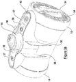
- the apparatus 10 includes a plurality of deflector members 36, 37 connected to the main body 12.
- the purpose of the deflector members 36, 37 is to provide protection to the main body 12 and also to assist a user in manoeuvring the apparatus whilst cleaning.
- the deflector members 36, 37 advantageously assist the user in manoeuvring the apparatus past fixed objects e.g. door frames, chairs, tables.
- User operable controls 38-40 are provided in recesses within the deflector members 37. The positioning of the user operable controls 38-40 in this location ensures that they are somewhat protected from any damage as a result of collisions between the apparatus and fixed objects.
- the user operable control 38 is pivotally moveable to control the opening of a lid 21 to the chamber 20.
- the user operable control 40 is the power button for providing electrical connection between a mains supply and the suction motor 18a.
- the user operable control 39 controls activation of the cable storage device 26 to cause retraction of the cable 28 for storage in the main body 12. It should be appreciated that other user operable controls could be provided within the spaces or recesses in the deflective members 37. Whilst no user operable controls are provided in the corresponding spaces in the deflector members 36 they could be provided if desired as an alternative or addition to the controls 38-40.
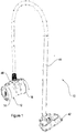
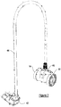
- the apparatus 10 includes a tool 42 for engaging a floor surface and a conduit/hose 44 connecting the floor tool 42 to the main body 12.
- a tool 42 for engaging a floor surface and a conduit/hose 44 connecting the floor tool 42 to the main body 12.
- conduit/hose 44 connecting the floor tool 42 to the main body 12.
- the main body 12 includes a primary air inlet 46 which is positioned on the main body 12, midway between the first and second ends of the main body 12.
- the primary air inlet 46 extends through a generally upwardly facing exterior surface of the main body 12.
- the primary air inlet 46 is for connection to the conduit/hose 44.
- the primary are inlet 46 includes a formation having an electrical connection for providing power to the floor tool 42, although it is not essential.
- the main body 12 also includes an opening 48 through which the cable 28 can exit from or enter towards the cable storage device 26.
- the chamber 20 is generally cylindrical and removably connected to the main body 12 such that it can be removed through the end of the main body 12 for emptying by the user.
- Inlet 22 is provided on a side wall of the chamber 20 and is in fluid communication with the primary air inlet 46.
- a pre-filter 50 is provided on the outlet 24 to remove any particulates present in the flow of air leaving the chamber 20 to prevent them from entering the fluid flow path 30 and causing any damage by coming into contact with the fan 18b and motor 18a.
- the source of suction 18, chamber 20 and cyclonic separator device 32 are positioned along the axis A of the main body 12 and, when powered, provide a suitable source of suction in order to draw air through the primary air inlet 46, cyclonic separator device 32 and pre-filter 50.
- a post-motor filter 52 Positioned around the motor 18a (near the wheel 16) is a post-motor filter 52. Air passes through this filter 52 and apertures 54 at the end of the main body 12 to atmosphere.
- the source of suction 18, the cable storage device 26 and the chamber 20 are positioned in a generally side by side configuration within the main body 12.
- the fluid flow path 30 is a cylindrically shaped passage having one end in fluid communication with the outlet 24 and the other end of which is in fluid communication with the source of suction 18.
- the cable storage device 26 is positioned substantially midway between the ends of the main body 12, between the source of suction 18 and the chamber 20 such that the component parts are sequentially aligned. In other embodiments the cable storage device 26 may be positioned in a different position away from the midway point and/or placed in a different sequential position with respect to the source of suction 18 and the chamber 20. The cable storage device 26 could be positioned elsewhere, for example between the motor 18a and the filter 52, or between the filter 50 and the suction fan 18b, or indeed in any other location within the interior of the main body 12.
- the cable storage device 26 is of an annular shape and has a space 60 within which the cable 28 is stored.
- the cable storage device 26 includes an annular moveable part 62 which is rotatable about the axis A around the fluid flow path 30.
- the cable storage device 26 includes a means for biasing the cable 28 to be pulled into an interior of the main body 12 via the opening 48 provided on the main body 12 so that the cable 28 is coiled around the moveable part 62.
- a free end of the cable 28 is connected to a plug 56 which, when the cable 28 is fully stored, is at least partially received in a recess 58 in the main body 12.
- the moveable part 62 is rotatable around the portion of the fluid flow path 30 and extends circumferentially around a surface of the fluid flow path.
- the moveable part 62 is thus parallel and coaxial with the axis A of the main body 12. This provides for an optimum use of the interior space of the main body 12 allowing for a more compact configuration of the surface cleaning apparatus 10. In other embodiments the moveable part 62 may only extend partially around the fluid flow path 30.
- the cable storage device 26 defines a space 64 into and through which the fluid flow path 30 extends and around which space 64 the cable storage device 26 follows a substantially annular path.
- the space 64 is formed substantially centrally of the cable storage device 26 so as to further minimise the space taken by the component parts and maximise the length of cable 28 which can be accommodated within the interior space of the main body 12.
- the space 64 is generally cylindrical and has an elongate axis which is substantially parallel and coaxial with the axis of the cable storage device 26.
- the cable storage device 26 has an axis which is substantially parallel with an axis of the source of suction 18, an axis of the chamber 20 and the axis A of the main body 12 so as to provide a generally substantially coaxial arrangement.
- the components may not be co-axial and, instead, their respective axes may be offset from one another and/or the axis A of the main body 12.
- the side by side configuration of the cable storage device 26, source of suction 18 and the chamber 20 means that the respective component parts are positioned along the axis A of the main body 12. In this way the component parts are in an end to end relationship by which it is meant that each component occupies a respective space which is separate from a space in which another component is positioned.
- the present invention could equally be applied to that of an upright type cleaner. More particularly, the configuration of having a cable storage device 26 positioned such that the fluid flow path 30 that connects the source of suction 18 to the chamber 20 extends through the cable storage device 26 provides for space savings which can equally apply to upright cleaners and other types of shapes of the main body 12.
- the fluid flow path 30 may be provided by an intergral portion of the cable storage device 26 such that the cable storage device 26 moves together with the portion of the fluid flow path 30 during use.
- the cable storage device 26 is supported on the fluid flow path 30 but it could, alternatively, be mounted and rotatable with the fluid flow path 30 in other embodiments.
- the cable storage device 26 includes means for biasing the cable 28 to be drawn into the interior of the main body 12
- embodiments are envisaged which include a manually operable means for winding the cable 28 into the main body 12.
- a manually operable means for winding the cable 28 into the main body 12 For example there could be a handle accessible outside of the main body 12 which a user moves so as to rotate the annular member 62 so as to wind the cable 28 into the interior of the main body 12.
- the cable storage device 26 includes the space 60 for storage of the cable 28 and the apparatus 10 includes an opening 48 through which the cable 28 can exit and enter the cable storage device 26.
- the apparatus 10 also includes a valve 66, in the form of pressure relief valve, which provides for fluid communication between the cable storage device space 60 and the source of suction 18.
- the valve 66 includes an actuator having a seal 67 which is mechanically operable to move between a closed position in which air is not permitted to flow from the space 60 to the source of suction 18, and an open position in which air is permitted to flow from the space 60 to the source of suction 18. In the closed position, the seal 67 prevents air from flowing from the valve 66 to the source of suction 18.
- the space 60 in which the cable 28 is stored is substantially sealed from atmosphere apart from the opening 48.
- the valve 66 is provided in a wall 68 between the cable storage device 26 and the space in which the source of suction 18 is positioned.
- the valve 66 is biased by a spring to the closed position ( Fig. 6a ) and is configured to move to the open position ( Fig. 6b ) in which it permits air to flow from the space 60 to the source of suction 18 when the pressure in the fluid flow path 30 reaches a predetermined threshold.
- the source of suction 18 will provide suction to the chamber 20 and primary air inlet 46 causing a drop in pressure. This will cause air to flow through the primary air inlet 46, through the cyclonic separator device 32 which separates dirt entrailed in the air, and the substantially cleaned air passes through the outlet 24 of the chamber 20 and pre-filter 50.
- the air will follow the fluid flow path 30 through the motor housing and to atmosphere through the apertures 54 provided in the end of the main body 12. This has the effect of cooling the motor 18a during operation and preventing overheating. This flow path is shown in Fig. 5 .
- valve 66 is a mechanical valve but in other embodiments it is envisaged that an automated valve is provided which is operated by electronic means.
- an automated valve is provided which is operated by electronic means.
- Embodiments of apparatus are envisaged which do not include a cyclonic separator device, but instead utilise a receptacle, bag or the like for collecting dirt which is supported within the chamber 20.
- embodiments are envisaged which do not include a cable storage device 26, although it is desirable for the apparatus to be provided with such a device in order to ensure compact storage of the electrical cable 28.
- the apparatus could be modified to be a “wet” system, i.e. utilising a source of cleaning fluid within the apparatus which is applied to the floor surface before being sucked back in to a chamber within the main body.
- the chamber 20 is capable of receiving dirt, which definition encompasses either directly receiving dirt or there being a bag or the like supported within the chamber 20 which itself collects dirt.
- the axis of the main body is a generally elongate axis thereof which in this example extends lengthwise of the apparatus between the first and second wheels.
Landscapes
- Engineering & Computer Science (AREA)
- Mechanical Engineering (AREA)
- Electric Suction Cleaners (AREA)
- Filters For Electric Vacuum Cleaners (AREA)
- Nozzles For Electric Vacuum Cleaners (AREA)
- Cleaning In General (AREA)
- Cyclones (AREA)
Claims (15)
- Oberflächenreinigungsvorrichtung (10), die Folgendes beinhaltet:eine Saugquelle (18);eine Schmutzaufnahmekammer (20), die einen Einlass (22) und einen Auslass (24) aufweist;eine Kabelaufbewahrungsvorrichtung (26) zum Aufbewahren eines Elektrokabels (28) zur Stromversorgung der Saugquelle; undeinen Fluidströmungsweg (30), der eine Fluidkommunikation zwischen dem Auslass der Kammer und der Saugquelle vorsieht;dadurch gekennzeichnet, dass sich mindestens ein Abschnitt des Fluidströmungswegs durch einen von der Kabelaufbewahrungsvorrichtung definierten Raum (64) erstreckt und die Kabelaufbewahrungsvorrichtung einem im Wesentlichen ringförmigen Weg um den Raum herum folgt.
- Oberflächenreinigungsvorrichtung nach Anspruch 1, worin die Saugquelle, die Schmutzaufnahmekammer und die Kabelaufbewahrungsvorrichtung in einer generellen Seite-an-Seite-Konfiguration positioniert sind.
- Oberflächenreinigungsvorrichtung nach Anspruch 1 oder Anspruch 2, die Folgendes beinhaltet:
einen Körper (12) mit einer länglichen Achse (A);
worin der Körper Folgendes beinhaltet:ein erstes Ende, das bevorzugt ein erstes Rad (14) beinhaltet, das bevorzugt an oder nahe dem ersten Ende des Körpers positioniert ist; undein zweites Ende, das bevorzugt ein zweites Rad (16) beinhaltet, das bevorzugt an oder nahe dem zweiten Ende des Körpers positioniert ist; undworin der Körper eine oder mehrere der Saugquelle, Kammer und Kabelaufbewahrungsvorrichtung aufnimmt;bevorzugt, worin die Achse des Hauptkörpers generell horizontal ist, wenn sowohl das erste als auch zweite Rad mit einer zu reinigenden Oberfläche in Eingriff sind. - Oberflächenreinigungsvorrichtung nach einem vorhergehenden Anspruch, worin eine Achse der Kabelaufbewahrungsvorrichtung im Wesentlichen parallel oder koaxial zu einer Achse der Saugquelle und/oder der Achse der Kammer und/oder des Körpers ist.
- Oberflächenreinigungsvorrichtung nach einem vorhergehenden Anspruch, wobei der Raum im Wesentlichen mittig in der Kabelaufbewahrungsvorrichtung gebildet ist; und/oder worin der Raum generell zylindrisch ist; und/oder worin der Raum eine längliche Achse im Wesentlichen parallel/koaxial zu einer Achse der Kabelaufbewahrungsvorrichtung aufweist.
- Oberflächenreinigungsvorrichtung nach einem vorhergehenden Anspruch, worin die Kabelaufbewahrungsvorrichtung zwischen der Saugquelle und der Schmutzaufnahmekammer positioniert ist, bevorzugt so, dass sie sequenziell ausgerichtet sind, bevorzugt, worin die Kabelaufbewahrungsvorrichtung im Wesentlichen in der Mitte zwischen den Enden des Körpers positioniert ist.
- Oberflächenreinigungsvorrichtung nach einem vorhergehenden Anspruch, worin die Kabelaufbewahrungsvorrichtung ein bewegliches Teil (62) beinhaltet, das um den Abschnitt des Fluidströmungswegs drehbar ist.
- Oberflächenreinigungsvorrichtung nach Anspruch 7, worin das bewegliche Teil im Wesentlichen ringförmig ist und sich teilweise oder ganz umfänglich um eine Oberfläche des Fluidströmungswegs erstreckt; und/oder worin das bewegliche Teil um die Achse der Kabelaufbewahrungsvorrichtung drehbar ist.
- Oberflächenreinigungsvorrichtung nach Anspruch 8, worin die Drehachse parallel oder koaxial zu der Achse des Körpers ist.
- Oberflächenreinigungsvorrichtung nach einem vorhergehenden Anspruch, worin die Kabelaufbewahrungsvorrichtung auf dem Fluidströmungsweg abgestützt und bevorzugt um diesen drehbar ist, bevorzugt, worin die Kabelaufbewahrungsvorrichtung an und bevorzugt drehbar mit dem Fluidströmungsweg montiert ist.
- Oberflächenreinigungsvorrichtung nach Anspruch 3 oder einem der Ansprüche 4 bis 10, wenn direkt oder indirekt von Anspruch 3 abhängig, worin der Körper einen primären Lufteinlass (46) beinhaltet, der im Wesentlichen in der Mitte zwischen dem ersten und zweiten Ende positioniert ist;
bevorzugt, worin sich der primäre Lufteinlass durch eine generell nach oben weisende Außenfläche des Körpers erstreckt. - Oberflächenreinigungsvorrichtung nach Anspruch 3 oder einem der Ansprüche 4 bis 11, wenn direkt oder indirekt von Anspruch 3 abhängig, worin die Oberflächenreinigungsvorrichtung eins oder mehrere oder alle von Folgendem beinhaltet:a) der Körper ist generell zylindrisch und ein Abschnitt des Körpers, der zwischen einem zentralen Bereich des Körpers und jedem Ende und/oder Rad des Körpers positioniert ist, hat einen Radius, der zunimmt, wenn er sich hin zu jedem Ende und/oder Rad erstreckt;b) der Körper hat eine generell konkave Außenfläche;c) eine Außenfläche des Körpers beinhaltet einen generell konkaven Abschnitt;d) der Körper nimmt die Schmutzaufnahmekammer auf;e) die Schmutzaufnahmekammer ist abnehmbar mit dem Körper verbunden;f) jedes Rad beinhaltet ein ringförmiges Element, das zur Drehung durch eine Außenfläche eines Teils des Körpers (15, 17) abgestützt ist;g) der Körper ist generell symmetrisch, bevorzugt um eine Ebene, die sich durch die Kabelaufbewahrungsvorrichtung erstreckt;h) die Vorrichtung beinhaltet einen mit einem Ende des Körpers verbundenen Griff (34);i) der Körper nimmt einen ersten Zyklonabscheider auf, bevorzugt, wobei der Körper einen weiteren zweiten Zyklonabscheider aufnimmt, der in Fluidkommunikation mit dem ersten Zyklonabscheider ist.
- Oberflächenreinigungsvorrichtung nach einem vorhergehenden Anspruch, einschließlich einer Öffnung, durch die das Kabel verläuft/austritt; worin die Vorrichtung ein Ventil beinhaltet, das einen Fluidfluss von dem Kabelaufbewahrungsvorrichtungsraum zu der Saugquelle gestattet.
- Oberflächenreinigungsvorrichtung nach Anspruch 13, worin die Oberflächenreinigungsvorrichtung eins oder mehrere oder alle von Folgendem beinhaltet:a) das Druckentlastungsventil ist dafür konfiguriert, einen Luftfluss von dem Raum zu der Saugquelle zu gestatten, wenn der Druck in dem Fluidströmungsweg eine vorbestimmte Schwelle erreicht;b) der Raum ist im Wesentlichen gegenüber der Atmosphäre abgedichtet, abgesehen von der Öffnung, durch die das Kabel verläuft, bevorzugt, worin der Raum gegenüber der Atmosphäre abgedichtet ist, abgesehen von der Öffnung, durch die das Kabel verläuft;c) das Ventil ist in einer Wand zwischen der Kabelaufbewahrungsvorrichtung und dem Raum, in dem die Saugquelle positioniert ist, bereitgestellt;d) der Fluidfluss durch das Ventil erfolgt im Wesentlichen nur mittels der Öffnung, durch die das Kabel verläuft, bevorzugt, worin der Fluidfluss durch das Ventil nur mittels der Öffnung erfolgt, durch die das Kabel verläuft, sogar noch bevorzugter, worin das Ventil ein Druckentlastungsventil ist, und am bevorzugtesten, worin das Druckentlastungsventil einen Aktor beinhaltet, der mechanisch betätigbar ist zur Bewegung zwischen einer geschlossenen Position, in der ein Luftfluss von dem Raum zu der Saugquelle nicht gestattet ist, und einer offenen Position, in der ein Luftfluss von dem Raum zu der Saugquelle gestattet ist.
- Oberflächenreinigungsvorrichtung nach einem vorhergehenden Anspruch, worin die Vorrichtung zur Boden- oder Stielausführung gehört.
Applications Claiming Priority (3)
| Application Number | Priority Date | Filing Date | Title |
|---|---|---|---|
| GB1319372.7A GB2519968A (en) | 2013-11-01 | 2013-11-01 | Surface cleaning Apparatus |
| GB1400998.9A GB2520092B (en) | 2013-11-01 | 2014-01-21 | Surface Cleaning apparatus |
| PCT/GB2014/050312 WO2015063446A1 (en) | 2013-11-01 | 2014-02-04 | Surface cleaning apparatus |
Publications (2)
| Publication Number | Publication Date |
|---|---|
| EP3062676A1 EP3062676A1 (de) | 2016-09-07 |
| EP3062676B1 true EP3062676B1 (de) | 2019-05-08 |
Family
ID=49767562
Family Applications (3)
| Application Number | Title | Priority Date | Filing Date |
|---|---|---|---|
| EP14706931.4A Withdrawn EP3062675A1 (de) | 2013-11-01 | 2014-02-04 | Oberflächenreinigungsvorrichtung |
| EP14706662.5A Active EP3062676B1 (de) | 2013-11-01 | 2014-02-04 | Oberflächenreinigungsvorrichtung |
| EP14706318.4A Withdrawn EP3062674A1 (de) | 2013-11-01 | 2014-02-04 | Oberflächenreinigungsvorrichtung |
Family Applications Before (1)
| Application Number | Title | Priority Date | Filing Date |
|---|---|---|---|
| EP14706931.4A Withdrawn EP3062675A1 (de) | 2013-11-01 | 2014-02-04 | Oberflächenreinigungsvorrichtung |
Family Applications After (1)
| Application Number | Title | Priority Date | Filing Date |
|---|---|---|---|
| EP14706318.4A Withdrawn EP3062674A1 (de) | 2013-11-01 | 2014-02-04 | Oberflächenreinigungsvorrichtung |
Country Status (6)
| Country | Link |
|---|---|
| US (3) | US20160249778A1 (de) |
| EP (3) | EP3062675A1 (de) |
| CN (3) | CN105848547B (de) |
| AU (3) | AU2014343485A1 (de) |
| GB (13) | GB2538642A (de) |
| WO (3) | WO2015063446A1 (de) |
Families Citing this family (10)
| Publication number | Priority date | Publication date | Assignee | Title |
|---|---|---|---|---|
| GB2533145A (en) * | 2014-12-11 | 2016-06-15 | Techtronic Ind Co Ltd | Surface cleaning apparatus |
| CN106137025A (zh) * | 2016-08-18 | 2016-11-23 | 苏州凯丽达电器有限公司 | 一种可收纳软管的行走吸尘器 |
| JP7174507B2 (ja) * | 2017-06-14 | 2022-11-17 | 東芝ライフスタイル株式会社 | 電気掃除機 |
| CN111031871B (zh) * | 2017-08-25 | 2022-04-19 | 株式会社牧田 | 吸尘器 |
| GB2569569B (en) | 2017-12-20 | 2021-04-21 | Dyson Technology Ltd | A filter assembly |
| EP3542693A1 (de) * | 2018-03-22 | 2019-09-25 | Hilti Aktiengesellschaft | Nass- und trockensauger |
| GB201913758D0 (en) * | 2019-09-24 | 2019-11-06 | Ge Oil And Gas Uk Ltd | Annulus connection |
| DE102020122626A1 (de) * | 2020-08-31 | 2022-03-03 | Miele & Cie. Kg | Beutelloser Staubsauger |
| CN113040669B (zh) * | 2021-03-16 | 2022-01-25 | 山东大学齐鲁医院(青岛) | 一种用于消化内科地面呕吐物清理的多功能清扫装置 |
| CN116138670A (zh) * | 2022-12-09 | 2023-05-23 | 山西嘉世达机器人技术有限公司 | 清洁装置 |
Family Cites Families (68)
| Publication number | Priority date | Publication date | Assignee | Title |
|---|---|---|---|---|
| US2871503A (en) * | 1948-12-27 | 1959-02-03 | Edgar P Senne | Vacuum cleaner on-and-off switching devices |
| US2769996A (en) * | 1953-12-21 | 1956-11-13 | Gen Electric | Mobile vacuum cleaner having a hose adapted to be used as a pushing or pulling means therefor |
| US2769998A (en) * | 1953-12-21 | 1956-11-13 | Gen Electric | Mobile vacuum cleaner having a hose adapted to be used as a pushing or pulling means therefor |
| US2991928A (en) * | 1958-05-20 | 1961-07-11 | Gen Electric | Low cost mobile vacuum cleaner |
| US3081478A (en) * | 1960-10-31 | 1963-03-19 | Nat Union Electric Corp | Latch for suction cleaner |
| US3015122A (en) * | 1961-01-04 | 1962-01-02 | Robert E Cook | Mobile electric vacuum cleaner |
| US3085279A (en) * | 1961-01-05 | 1963-04-16 | Lewyt Corp | Vacuum cleaner assembly |
| DE1176327B (de) * | 1962-04-24 | 1964-08-20 | Licentia Gmbh | Vorrichtung zum Verstellen der Saugleistung von Staubsaugern |
| US3490089A (en) * | 1967-11-24 | 1970-01-20 | Nat Union Electric Corp | Combination handle and switch actuator |
| DE2213716A1 (de) * | 1972-03-21 | 1973-09-27 | Siemens Elektrogeraete Gmbh | Bodenstaubsauger |
| US3883922A (en) * | 1973-01-02 | 1975-05-20 | Eugene T Fleischhauer | Vacuum cleaners |
| JPS5353163A (en) * | 1976-10-22 | 1978-05-15 | Mitsubishi Electric Corp | Electric vacuum cleaner |
| JPS54100148A (en) * | 1978-01-25 | 1979-08-07 | Matsushita Electric Ind Co Ltd | Electric cleaner |
| DE2818317A1 (de) * | 1978-04-26 | 1980-03-13 | Siemens Ag | Staubsauger |
| DE3337460A1 (de) * | 1983-10-14 | 1985-04-25 | Siemens AG, 1000 Berlin und 8000 München | Staubsauger |
| DE3606378A1 (de) * | 1986-02-27 | 1987-09-03 | Vorwerk Co Interholding | Kabelaufwickelvorrichtung fuer staubsauger |
| JPH03111251A (ja) * | 1989-09-14 | 1991-05-13 | Showa Denko Kk | 缶様容器蓋およびその製法 |
| JP3063133B2 (ja) * | 1990-09-14 | 2000-07-12 | 松下電器産業株式会社 | 電気掃除機 |
| JPH04303407A (ja) * | 1991-03-29 | 1992-10-27 | Sanyo Electric Co Ltd | 電気掃除機 |
| JP3232688B2 (ja) * | 1992-09-25 | 2001-11-26 | 松下電器産業株式会社 | 電気掃除機 |
| CA2113965C (en) * | 1993-08-04 | 1997-03-04 | William J. Rakocy | Tip resistant canister for upright vacuum cleaners |
| JP3343243B2 (ja) * | 1995-07-31 | 2002-11-11 | 有限会社三輪サイエンス研究所 | 還流式又は吸引式掃除機 |
| CH691565A5 (fr) * | 1996-09-26 | 2001-08-31 | Certech Sa | Aspirateur pour déchets ménagers. |
| US6735817B2 (en) * | 1998-01-09 | 2004-05-18 | Royal Appliance Mfg. Co. | Upright vacuum cleaner with cyclonic air flow |
| US6168641B1 (en) * | 1998-06-26 | 2001-01-02 | Akteibolaget Electrolux | Cyclone separator device for a vacuum cleaner |
| US6145160A (en) * | 1998-11-20 | 2000-11-14 | Primus Holdings, L.P. | Tank-type vacuum cleaner |
| GB2344777A (en) * | 1998-12-18 | 2000-06-21 | Notetry Ltd | Horizontal cyclonic separator with single fin or baffle |
| DE19907051A1 (de) * | 1999-02-19 | 2000-08-24 | Bsh Bosch Siemens Hausgeraete | Reinigungsgerät |
| CN1135098C (zh) * | 1999-06-19 | 2004-01-21 | 韩基焕 | 自驱动的自动吸尘器 |
| JP2001029276A (ja) * | 1999-07-23 | 2001-02-06 | Hitachi Ltd | 電気掃除機 |
| DE19943190C1 (de) * | 1999-09-09 | 2001-01-11 | Miele & Cie | Staubsauger mit einem Gerätegehäuse und einer Steckdose für eine Elektrobürste oder dergl. |
| JP2001128910A (ja) * | 1999-11-08 | 2001-05-15 | Toshiba Tec Corp | 電気掃除機 |
| IT1315385B1 (it) * | 2000-02-01 | 2003-02-10 | T P A Impex Spa | Gruppo di sterzo particolarmente per macchine di pulizia in ambitodomestico e/o industriale. |
| CN1143651C (zh) * | 2000-03-01 | 2004-03-31 | 松下电器产业株式会社 | 电动吸尘器 |
| DE60116336T2 (de) * | 2000-09-01 | 2006-08-31 | Royal Appliance Mfg. Co., Glenwillow | Beutelloser staubsauger |
| AU779644B2 (en) * | 2000-10-31 | 2005-02-03 | Samsung Gwangju Electronics Co., Ltd. | Suction port assembly of vacuum cleaner |
| JP2002360482A (ja) * | 2002-03-15 | 2002-12-17 | Matsushita Electric Ind Co Ltd | 自走式掃除機 |
| GB2391459A (en) * | 2002-08-09 | 2004-02-11 | Dyson Ltd | A surface treating appliance with increased manoeuverability |
| JP2005015178A (ja) * | 2003-06-27 | 2005-01-20 | Toshiba Tec Corp | コードリール及びコードリールを用いた電気機器 |
| DE102004001591A1 (de) * | 2004-01-09 | 2005-08-04 | AEG Hausgeräte GmbH | Staubsauger |
| KR100601897B1 (ko) * | 2004-04-16 | 2006-07-19 | 삼성광주전자 주식회사 | 사이클론 집진장치 및 이를 이용한 진공청소기 |
| KR100577280B1 (ko) * | 2005-01-04 | 2006-05-10 | 엘지전자 주식회사 | 진공 청소기 |
| JP2006326170A (ja) * | 2005-05-30 | 2006-12-07 | Toshiba Tec Corp | コードリール付電気機器 |
| CN1887162A (zh) * | 2005-06-30 | 2007-01-03 | 乐金电子(天津)电器有限公司 | 真空吸尘器 |
| KR100809617B1 (ko) * | 2007-03-26 | 2008-03-05 | 주식회사코네트인더스트리 | 회전 범퍼를 가진 진공 청소기 |
| US8062398B2 (en) * | 2008-12-19 | 2011-11-22 | Bissell Homecare, Inc. | Vacuum cleaner and cyclone module therefor |
| GB2468153A (en) * | 2009-02-27 | 2010-09-01 | Dyson Technology Ltd | A silencing arrangement |
| GB2469049B (en) * | 2009-03-31 | 2013-04-17 | Dyson Technology Ltd | A cleaning appliance with steering mechanism |
| GB2469050B (en) * | 2009-03-31 | 2013-01-02 | Dyson Technology Ltd | A cleaning appliance with steering member |
| GB2469042B (en) * | 2009-03-31 | 2012-07-25 | Dyson Technology Ltd | A cleaning appliance |
| KR20100116834A (ko) * | 2009-04-23 | 2010-11-02 | 삼성광주전자 주식회사 | 직립형 진공청소기 |
| CA2953105C (en) * | 2009-07-30 | 2020-02-11 | Omachron Intellectual Property Inc. | Surface cleaning apparatus |
| WO2011132323A1 (ja) * | 2010-04-22 | 2011-10-27 | 三立機器株式会社 | 乾湿両用バキュームクリーナー |
| DE102010030222B3 (de) * | 2010-06-17 | 2011-07-28 | BSH Bosch und Siemens Hausgeräte GmbH, 81739 | Staubsauger mit Nebenluftventil |
| GB201012751D0 (en) * | 2010-07-29 | 2010-09-15 | Miles Alexander | Dual purpose vacuum cleaner for use on floor and stairs |
| GB2487398B (en) * | 2011-01-20 | 2014-12-03 | Dyson Technology Ltd | A cylinder vacuum cleaner |
| US8646149B2 (en) * | 2011-03-03 | 2014-02-11 | G.B.D. Corp. | Filter housing construction for a surface cleaning apparatus |
| US9101252B2 (en) * | 2011-03-03 | 2015-08-11 | G.B.D. Corp. | Configuration of a surface cleaning apparatus |
| US8769767B2 (en) * | 2011-03-03 | 2014-07-08 | G.B.D. Corp. | Removable cyclone chamber and dirt collection assembly for a surface cleaning apparatus |
| US8528160B2 (en) * | 2011-03-03 | 2013-09-10 | G.B.D. Corp. | Suction motor and fan assembly housing construction for a surface cleaning apparatus |
| US8739357B2 (en) * | 2011-03-03 | 2014-06-03 | G.B.D. Corp | Filter construction for a surface cleaning apparatus |
| US8763202B2 (en) * | 2011-03-03 | 2014-07-01 | G.B.D. Corp. | Cyclone chamber and dirt collection assembly for a surface cleaning apparatus |
| GB2489266B8 (en) * | 2011-03-23 | 2015-04-15 | Techtronic Floor Care Tech Ltd | Suction cleaner |
| US8522395B2 (en) * | 2011-07-04 | 2013-09-03 | Samsung Electronics Co., Ltd. | Vacuum cleaner having shredder |
| JP2013111228A (ja) * | 2011-11-29 | 2013-06-10 | Panasonic Corp | 縦型電気掃除機 |
| GB2503254B (en) * | 2012-06-20 | 2014-12-17 | Dyson Technology Ltd | A cleaning appliance |
| GB2504704A (en) * | 2012-08-06 | 2014-02-12 | Glyn Hughes | Vacuum cleaner |
| KR102115505B1 (ko) * | 2012-11-13 | 2020-05-27 | 삼성전자주식회사 | 휴대용 진공청소기 |
-
2013
- 2013-11-01 GB GB1612068.5A patent/GB2538642A/en not_active Withdrawn
- 2013-11-01 GB GB1612070.1A patent/GB2538182A/en not_active Withdrawn
- 2013-11-01 GB GB1612074.3A patent/GB2538184B/en not_active Expired - Fee Related
- 2013-11-01 GB GB1612071.9A patent/GB2538183B/en not_active Expired - Fee Related
- 2013-11-01 GB GB1319372.7A patent/GB2519968A/en not_active Withdrawn
- 2013-11-01 GB GB1612066.9A patent/GB2538641A/en not_active Withdrawn
- 2013-11-01 GB GB1612062.8A patent/GB2538640A/en not_active Withdrawn
- 2013-11-01 GB GB1612069.3A patent/GB2538643A/en not_active Withdrawn
- 2013-11-01 GB GB1612086.7A patent/GB2538186A/en not_active Withdrawn
- 2013-11-01 GB GB1612088.3A patent/GB2538187B/en not_active Expired - Fee Related
- 2013-11-01 GB GB1612084.2A patent/GB2538185B/en not_active Expired - Fee Related
-
2014
- 2014-01-21 GB GB1400998.9A patent/GB2520092B/en not_active Expired - Fee Related
- 2014-01-21 GB GB1401002.9A patent/GB2523304A/en not_active Withdrawn
- 2014-02-04 CN CN201480069828.0A patent/CN105848547B/zh not_active Expired - Fee Related
- 2014-02-04 AU AU2014343485A patent/AU2014343485A1/en not_active Abandoned
- 2014-02-04 US US15/033,480 patent/US20160249778A1/en not_active Abandoned
- 2014-02-04 US US15/033,468 patent/US20160262587A1/en not_active Abandoned
- 2014-02-04 CN CN201480070197.4A patent/CN105828683A/zh active Pending
- 2014-02-04 EP EP14706931.4A patent/EP3062675A1/de not_active Withdrawn
- 2014-02-04 WO PCT/GB2014/050312 patent/WO2015063446A1/en not_active Ceased
- 2014-02-04 WO PCT/GB2014/050310 patent/WO2015063445A1/en not_active Ceased
- 2014-02-04 EP EP14706662.5A patent/EP3062676B1/de active Active
- 2014-02-04 CN CN201480069378.5A patent/CN105828682A/zh active Pending
- 2014-02-04 WO PCT/GB2014/050313 patent/WO2015063447A1/en not_active Ceased
- 2014-02-04 AU AU2014343483A patent/AU2014343483A1/en not_active Abandoned
- 2014-02-04 AU AU2014343484A patent/AU2014343484A1/en not_active Abandoned
- 2014-02-04 EP EP14706318.4A patent/EP3062674A1/de not_active Withdrawn
- 2014-02-04 US US15/033,463 patent/US20160249777A1/en not_active Abandoned
Non-Patent Citations (1)
| Title |
|---|
| None * |
Also Published As
Similar Documents
| Publication | Publication Date | Title |
|---|---|---|
| EP3062676B1 (de) | Oberflächenreinigungsvorrichtung | |
| JP5179554B2 (ja) | 表面処理電気器具 | |
| JP5317374B2 (ja) | 表面処理電気器具 | |
| JP5042350B2 (ja) | 表面処理電気器具 | |
| JP5188559B2 (ja) | 表面処理電気器具 | |
| JP5179555B2 (ja) | 表面処理電気器具 | |
| CN107405031B (zh) | 排空站 | |
| US7992252B2 (en) | Vacuum cleaner | |
| EP2688453B1 (de) | Staubsauger | |
| WO2016002893A1 (ja) | 電気掃除機 | |
| US20140075712A1 (en) | Portable vacuuming apparatus | |
| JP2016059639A (ja) | 掃除機本体および電気掃除機 |
Legal Events
| Date | Code | Title | Description |
|---|---|---|---|
| PUAI | Public reference made under article 153(3) epc to a published international application that has entered the european phase |
Free format text: ORIGINAL CODE: 0009012 |
|
| 17P | Request for examination filed |
Effective date: 20160523 |
|
| AK | Designated contracting states |
Kind code of ref document: A1 Designated state(s): AL AT BE BG CH CY CZ DE DK EE ES FI FR GB GR HR HU IE IS IT LI LT LU LV MC MK MT NL NO PL PT RO RS SE SI SK SM TR |
|
| AX | Request for extension of the european patent |
Extension state: BA ME |
|
| DAX | Request for extension of the european patent (deleted) | ||
| GRAP | Despatch of communication of intention to grant a patent |
Free format text: ORIGINAL CODE: EPIDOSNIGR1 |
|
| STAA | Information on the status of an ep patent application or granted ep patent |
Free format text: STATUS: GRANT OF PATENT IS INTENDED |
|
| INTG | Intention to grant announced |
Effective date: 20181129 |
|
| GRAS | Grant fee paid |
Free format text: ORIGINAL CODE: EPIDOSNIGR3 |
|
| GRAA | (expected) grant |
Free format text: ORIGINAL CODE: 0009210 |
|
| STAA | Information on the status of an ep patent application or granted ep patent |
Free format text: STATUS: THE PATENT HAS BEEN GRANTED |
|
| AK | Designated contracting states |
Kind code of ref document: B1 Designated state(s): AL AT BE BG CH CY CZ DE DK EE ES FI FR GB GR HR HU IE IS IT LI LT LU LV MC MK MT NL NO PL PT RO RS SE SI SK SM TR |
|
| REG | Reference to a national code |
Ref country code: GB Ref legal event code: FG4D |
|
| REG | Reference to a national code |
Ref country code: CH Ref legal event code: EP Ref country code: AT Ref legal event code: REF Ref document number: 1128872 Country of ref document: AT Kind code of ref document: T Effective date: 20190515 |
|
| REG | Reference to a national code |
Ref country code: DE Ref legal event code: R096 Ref document number: 602014046208 Country of ref document: DE Ref country code: IE Ref legal event code: FG4D |
|
| REG | Reference to a national code |
Ref country code: NL Ref legal event code: MP Effective date: 20190508 |
|
| REG | Reference to a national code |
Ref country code: LT Ref legal event code: MG4D |
|
| PG25 | Lapsed in a contracting state [announced via postgrant information from national office to epo] |
Ref country code: ES Free format text: LAPSE BECAUSE OF FAILURE TO SUBMIT A TRANSLATION OF THE DESCRIPTION OR TO PAY THE FEE WITHIN THE PRESCRIBED TIME-LIMIT Effective date: 20190508 Ref country code: SE Free format text: LAPSE BECAUSE OF FAILURE TO SUBMIT A TRANSLATION OF THE DESCRIPTION OR TO PAY THE FEE WITHIN THE PRESCRIBED TIME-LIMIT Effective date: 20190508 Ref country code: AL Free format text: LAPSE BECAUSE OF FAILURE TO SUBMIT A TRANSLATION OF THE DESCRIPTION OR TO PAY THE FEE WITHIN THE PRESCRIBED TIME-LIMIT Effective date: 20190508 Ref country code: PT Free format text: LAPSE BECAUSE OF FAILURE TO SUBMIT A TRANSLATION OF THE DESCRIPTION OR TO PAY THE FEE WITHIN THE PRESCRIBED TIME-LIMIT Effective date: 20190908 Ref country code: FI Free format text: LAPSE BECAUSE OF FAILURE TO SUBMIT A TRANSLATION OF THE DESCRIPTION OR TO PAY THE FEE WITHIN THE PRESCRIBED TIME-LIMIT Effective date: 20190508 Ref country code: NO Free format text: LAPSE BECAUSE OF FAILURE TO SUBMIT A TRANSLATION OF THE DESCRIPTION OR TO PAY THE FEE WITHIN THE PRESCRIBED TIME-LIMIT Effective date: 20190808 Ref country code: HR Free format text: LAPSE BECAUSE OF FAILURE TO SUBMIT A TRANSLATION OF THE DESCRIPTION OR TO PAY THE FEE WITHIN THE PRESCRIBED TIME-LIMIT Effective date: 20190508 Ref country code: LT Free format text: LAPSE BECAUSE OF FAILURE TO SUBMIT A TRANSLATION OF THE DESCRIPTION OR TO PAY THE FEE WITHIN THE PRESCRIBED TIME-LIMIT Effective date: 20190508 Ref country code: NL Free format text: LAPSE BECAUSE OF FAILURE TO SUBMIT A TRANSLATION OF THE DESCRIPTION OR TO PAY THE FEE WITHIN THE PRESCRIBED TIME-LIMIT Effective date: 20190508 |
|
| PG25 | Lapsed in a contracting state [announced via postgrant information from national office to epo] |
Ref country code: RS Free format text: LAPSE BECAUSE OF FAILURE TO SUBMIT A TRANSLATION OF THE DESCRIPTION OR TO PAY THE FEE WITHIN THE PRESCRIBED TIME-LIMIT Effective date: 20190508 Ref country code: BG Free format text: LAPSE BECAUSE OF FAILURE TO SUBMIT A TRANSLATION OF THE DESCRIPTION OR TO PAY THE FEE WITHIN THE PRESCRIBED TIME-LIMIT Effective date: 20190808 Ref country code: GR Free format text: LAPSE BECAUSE OF FAILURE TO SUBMIT A TRANSLATION OF THE DESCRIPTION OR TO PAY THE FEE WITHIN THE PRESCRIBED TIME-LIMIT Effective date: 20190809 Ref country code: LV Free format text: LAPSE BECAUSE OF FAILURE TO SUBMIT A TRANSLATION OF THE DESCRIPTION OR TO PAY THE FEE WITHIN THE PRESCRIBED TIME-LIMIT Effective date: 20190508 |
|
| REG | Reference to a national code |
Ref country code: AT Ref legal event code: MK05 Ref document number: 1128872 Country of ref document: AT Kind code of ref document: T Effective date: 20190508 |
|
| PG25 | Lapsed in a contracting state [announced via postgrant information from national office to epo] |
Ref country code: DK Free format text: LAPSE BECAUSE OF FAILURE TO SUBMIT A TRANSLATION OF THE DESCRIPTION OR TO PAY THE FEE WITHIN THE PRESCRIBED TIME-LIMIT Effective date: 20190508 Ref country code: EE Free format text: LAPSE BECAUSE OF FAILURE TO SUBMIT A TRANSLATION OF THE DESCRIPTION OR TO PAY THE FEE WITHIN THE PRESCRIBED TIME-LIMIT Effective date: 20190508 Ref country code: AT Free format text: LAPSE BECAUSE OF FAILURE TO SUBMIT A TRANSLATION OF THE DESCRIPTION OR TO PAY THE FEE WITHIN THE PRESCRIBED TIME-LIMIT Effective date: 20190508 Ref country code: SK Free format text: LAPSE BECAUSE OF FAILURE TO SUBMIT A TRANSLATION OF THE DESCRIPTION OR TO PAY THE FEE WITHIN THE PRESCRIBED TIME-LIMIT Effective date: 20190508 Ref country code: RO Free format text: LAPSE BECAUSE OF FAILURE TO SUBMIT A TRANSLATION OF THE DESCRIPTION OR TO PAY THE FEE WITHIN THE PRESCRIBED TIME-LIMIT Effective date: 20190508 Ref country code: CZ Free format text: LAPSE BECAUSE OF FAILURE TO SUBMIT A TRANSLATION OF THE DESCRIPTION OR TO PAY THE FEE WITHIN THE PRESCRIBED TIME-LIMIT Effective date: 20190508 |
|
| REG | Reference to a national code |
Ref country code: DE Ref legal event code: R097 Ref document number: 602014046208 Country of ref document: DE |
|
| PG25 | Lapsed in a contracting state [announced via postgrant information from national office to epo] |
Ref country code: SM Free format text: LAPSE BECAUSE OF FAILURE TO SUBMIT A TRANSLATION OF THE DESCRIPTION OR TO PAY THE FEE WITHIN THE PRESCRIBED TIME-LIMIT Effective date: 20190508 Ref country code: IT Free format text: LAPSE BECAUSE OF FAILURE TO SUBMIT A TRANSLATION OF THE DESCRIPTION OR TO PAY THE FEE WITHIN THE PRESCRIBED TIME-LIMIT Effective date: 20190508 |
|
| PLBE | No opposition filed within time limit |
Free format text: ORIGINAL CODE: 0009261 |
|
| STAA | Information on the status of an ep patent application or granted ep patent |
Free format text: STATUS: NO OPPOSITION FILED WITHIN TIME LIMIT |
|
| PG25 | Lapsed in a contracting state [announced via postgrant information from national office to epo] |
Ref country code: TR Free format text: LAPSE BECAUSE OF FAILURE TO SUBMIT A TRANSLATION OF THE DESCRIPTION OR TO PAY THE FEE WITHIN THE PRESCRIBED TIME-LIMIT Effective date: 20190508 |
|
| 26N | No opposition filed |
Effective date: 20200211 |
|
| PG25 | Lapsed in a contracting state [announced via postgrant information from national office to epo] |
Ref country code: PL Free format text: LAPSE BECAUSE OF FAILURE TO SUBMIT A TRANSLATION OF THE DESCRIPTION OR TO PAY THE FEE WITHIN THE PRESCRIBED TIME-LIMIT Effective date: 20190508 |
|
| PG25 | Lapsed in a contracting state [announced via postgrant information from national office to epo] |
Ref country code: SI Free format text: LAPSE BECAUSE OF FAILURE TO SUBMIT A TRANSLATION OF THE DESCRIPTION OR TO PAY THE FEE WITHIN THE PRESCRIBED TIME-LIMIT Effective date: 20190508 |
|
| REG | Reference to a national code |
Ref country code: CH Ref legal event code: PL |
|
| REG | Reference to a national code |
Ref country code: BE Ref legal event code: MM Effective date: 20200229 |
|
| PG25 | Lapsed in a contracting state [announced via postgrant information from national office to epo] |
Ref country code: MC Free format text: LAPSE BECAUSE OF FAILURE TO SUBMIT A TRANSLATION OF THE DESCRIPTION OR TO PAY THE FEE WITHIN THE PRESCRIBED TIME-LIMIT Effective date: 20190508 Ref country code: LU Free format text: LAPSE BECAUSE OF NON-PAYMENT OF DUE FEES Effective date: 20200204 |
|
| PG25 | Lapsed in a contracting state [announced via postgrant information from national office to epo] |
Ref country code: LI Free format text: LAPSE BECAUSE OF NON-PAYMENT OF DUE FEES Effective date: 20200229 Ref country code: CH Free format text: LAPSE BECAUSE OF NON-PAYMENT OF DUE FEES Effective date: 20200229 |
|
| PG25 | Lapsed in a contracting state [announced via postgrant information from national office to epo] |
Ref country code: IE Free format text: LAPSE BECAUSE OF NON-PAYMENT OF DUE FEES Effective date: 20200204 |
|
| PG25 | Lapsed in a contracting state [announced via postgrant information from national office to epo] |
Ref country code: BE Free format text: LAPSE BECAUSE OF NON-PAYMENT OF DUE FEES Effective date: 20200229 |
|
| PGFP | Annual fee paid to national office [announced via postgrant information from national office to epo] |
Ref country code: DE Payment date: 20220225 Year of fee payment: 9 |
|
| PG25 | Lapsed in a contracting state [announced via postgrant information from national office to epo] |
Ref country code: MT Free format text: LAPSE BECAUSE OF FAILURE TO SUBMIT A TRANSLATION OF THE DESCRIPTION OR TO PAY THE FEE WITHIN THE PRESCRIBED TIME-LIMIT Effective date: 20190508 Ref country code: CY Free format text: LAPSE BECAUSE OF FAILURE TO SUBMIT A TRANSLATION OF THE DESCRIPTION OR TO PAY THE FEE WITHIN THE PRESCRIBED TIME-LIMIT Effective date: 20190508 |
|
| PGFP | Annual fee paid to national office [announced via postgrant information from national office to epo] |
Ref country code: FR Payment date: 20220223 Year of fee payment: 9 |
|
| PG25 | Lapsed in a contracting state [announced via postgrant information from national office to epo] |
Ref country code: MK Free format text: LAPSE BECAUSE OF FAILURE TO SUBMIT A TRANSLATION OF THE DESCRIPTION OR TO PAY THE FEE WITHIN THE PRESCRIBED TIME-LIMIT Effective date: 20190508 Ref country code: IS Free format text: LAPSE BECAUSE OF FAILURE TO SUBMIT A TRANSLATION OF THE DESCRIPTION OR TO PAY THE FEE WITHIN THE PRESCRIBED TIME-LIMIT Effective date: 20190908 |
|
| PGFP | Annual fee paid to national office [announced via postgrant information from national office to epo] |
Ref country code: GB Payment date: 20230227 Year of fee payment: 10 |
|
| P01 | Opt-out of the competence of the unified patent court (upc) registered |
Effective date: 20230613 |
|
| REG | Reference to a national code |
Ref country code: DE Ref legal event code: R119 Ref document number: 602014046208 Country of ref document: DE |
|
| PG25 | Lapsed in a contracting state [announced via postgrant information from national office to epo] |
Ref country code: FR Free format text: LAPSE BECAUSE OF NON-PAYMENT OF DUE FEES Effective date: 20230228 Ref country code: DE Free format text: LAPSE BECAUSE OF NON-PAYMENT OF DUE FEES Effective date: 20230901 |
|
| GBPC | Gb: european patent ceased through non-payment of renewal fee |
Effective date: 20240204 |
|
| PG25 | Lapsed in a contracting state [announced via postgrant information from national office to epo] |
Ref country code: GB Free format text: LAPSE BECAUSE OF NON-PAYMENT OF DUE FEES Effective date: 20240204 |
|
| PG25 | Lapsed in a contracting state [announced via postgrant information from national office to epo] |
Ref country code: GB Free format text: LAPSE BECAUSE OF NON-PAYMENT OF DUE FEES Effective date: 20240204 |