EP3062043A2 - Trockner - Google Patents
Trockner Download PDFInfo
- Publication number
- EP3062043A2 EP3062043A2 EP16157375.3A EP16157375A EP3062043A2 EP 3062043 A2 EP3062043 A2 EP 3062043A2 EP 16157375 A EP16157375 A EP 16157375A EP 3062043 A2 EP3062043 A2 EP 3062043A2
- Authority
- EP
- European Patent Office
- Prior art keywords
- refrigerant
- dryer
- water
- housing
- container
- Prior art date
- Legal status (The legal status is an assumption and is not a legal conclusion. Google has not performed a legal analysis and makes no representation as to the accuracy of the status listed.)
- Withdrawn
Links
- 239000003507 refrigerant Substances 0.000 claims abstract description 69
- 239000000463 material Substances 0.000 claims abstract description 61
- XLYOFNOQVPJJNP-UHFFFAOYSA-N water Substances O XLYOFNOQVPJJNP-UHFFFAOYSA-N 0.000 claims abstract description 25
- 238000001035 drying Methods 0.000 claims abstract description 12
- 238000006243 chemical reaction Methods 0.000 claims abstract description 11
- 239000007795 chemical reaction product Substances 0.000 claims abstract description 6
- 238000002425 crystallisation Methods 0.000 claims abstract description 3
- 230000008025 crystallization Effects 0.000 claims abstract description 3
- OSGAYBCDTDRGGQ-UHFFFAOYSA-L calcium sulfate Chemical compound [Ca+2].[O-]S([O-])(=O)=O OSGAYBCDTDRGGQ-UHFFFAOYSA-L 0.000 claims description 10
- 229910000838 Al alloy Inorganic materials 0.000 claims description 7
- XAGFODPZIPBFFR-UHFFFAOYSA-N aluminium Chemical compound [Al] XAGFODPZIPBFFR-UHFFFAOYSA-N 0.000 claims description 7
- 229910052782 aluminium Inorganic materials 0.000 claims description 7
- 239000007788 liquid Substances 0.000 claims description 6
- OYPRJOBELJOOCE-UHFFFAOYSA-N Calcium Chemical compound [Ca] OYPRJOBELJOOCE-UHFFFAOYSA-N 0.000 claims description 5
- FYYHWMGAXLPEAU-UHFFFAOYSA-N Magnesium Chemical compound [Mg] FYYHWMGAXLPEAU-UHFFFAOYSA-N 0.000 claims description 5
- 239000006096 absorbing agent Substances 0.000 claims description 5
- 229910052791 calcium Inorganic materials 0.000 claims description 5
- 239000011575 calcium Substances 0.000 claims description 5
- 239000000292 calcium oxide Substances 0.000 claims description 5
- ODINCKMPIJJUCX-UHFFFAOYSA-N calcium oxide Inorganic materials [Ca]=O ODINCKMPIJJUCX-UHFFFAOYSA-N 0.000 claims description 5
- 239000001175 calcium sulphate Substances 0.000 claims description 5
- 235000011132 calcium sulphate Nutrition 0.000 claims description 5
- 229910052749 magnesium Inorganic materials 0.000 claims description 5
- 239000011777 magnesium Substances 0.000 claims description 5
- BRPQOXSCLDDYGP-UHFFFAOYSA-N calcium oxide Chemical compound [O-2].[Ca+2] BRPQOXSCLDDYGP-UHFFFAOYSA-N 0.000 claims description 4
- 238000005260 corrosion Methods 0.000 claims description 4
- 230000007797 corrosion Effects 0.000 claims description 4
- 239000000047 product Substances 0.000 claims description 4
- PNEYBMLMFCGWSK-UHFFFAOYSA-N aluminium oxide Inorganic materials [O-2].[O-2].[O-2].[Al+3].[Al+3] PNEYBMLMFCGWSK-UHFFFAOYSA-N 0.000 claims description 3
- 239000004744 fabric Substances 0.000 claims description 3
- 239000010726 refrigerant oil Substances 0.000 claims description 3
- 230000000717 retained effect Effects 0.000 claims description 3
- 239000000126 substance Substances 0.000 claims description 3
- 238000010348 incorporation Methods 0.000 claims description 2
- 239000011148 porous material Substances 0.000 claims description 2
- 239000010457 zeolite Substances 0.000 description 12
- 229910021536 Zeolite Inorganic materials 0.000 description 10
- HNPSIPDUKPIQMN-UHFFFAOYSA-N dioxosilane;oxo(oxoalumanyloxy)alumane Chemical compound O=[Si]=O.O=[Al]O[Al]=O HNPSIPDUKPIQMN-UHFFFAOYSA-N 0.000 description 10
- 239000012530 fluid Substances 0.000 description 7
- 238000010521 absorption reaction Methods 0.000 description 4
- 239000003921 oil Substances 0.000 description 4
- 235000012255 calcium oxide Nutrition 0.000 description 3
- 239000008187 granular material Substances 0.000 description 2
- TWNQGVIAIRXVLR-UHFFFAOYSA-N oxo(oxoalumanyloxy)alumane Chemical compound O=[Al]O[Al]=O TWNQGVIAIRXVLR-UHFFFAOYSA-N 0.000 description 2
- 239000004952 Polyamide Substances 0.000 description 1
- VYPSYNLAJGMNEJ-UHFFFAOYSA-N Silicium dioxide Chemical compound O=[Si]=O VYPSYNLAJGMNEJ-UHFFFAOYSA-N 0.000 description 1
- 238000004378 air conditioning Methods 0.000 description 1
- 230000009918 complex formation Effects 0.000 description 1
- 230000000694 effects Effects 0.000 description 1
- 238000001914 filtration Methods 0.000 description 1
- 238000009434 installation Methods 0.000 description 1
- 230000002427 irreversible effect Effects 0.000 description 1
- 238000004519 manufacturing process Methods 0.000 description 1
- 239000004033 plastic Substances 0.000 description 1
- 229920002647 polyamide Polymers 0.000 description 1
- 229920000642 polymer Polymers 0.000 description 1
- 239000000843 powder Substances 0.000 description 1
- 238000005057 refrigeration Methods 0.000 description 1
- 239000000741 silica gel Substances 0.000 description 1
- 229910002027 silica gel Inorganic materials 0.000 description 1
Images
Classifications
-
- F—MECHANICAL ENGINEERING; LIGHTING; HEATING; WEAPONS; BLASTING
- F25—REFRIGERATION OR COOLING; COMBINED HEATING AND REFRIGERATION SYSTEMS; HEAT PUMP SYSTEMS; MANUFACTURE OR STORAGE OF ICE; LIQUEFACTION SOLIDIFICATION OF GASES
- F25B—REFRIGERATION MACHINES, PLANTS OR SYSTEMS; COMBINED HEATING AND REFRIGERATION SYSTEMS; HEAT PUMP SYSTEMS
- F25B43/00—Arrangements for separating or purifying gases or liquids; Arrangements for vaporising the residuum of liquid refrigerant, e.g. by heat
- F25B43/003—Filters
-
- B—PERFORMING OPERATIONS; TRANSPORTING
- B01—PHYSICAL OR CHEMICAL PROCESSES OR APPARATUS IN GENERAL
- B01J—CHEMICAL OR PHYSICAL PROCESSES, e.g. CATALYSIS OR COLLOID CHEMISTRY; THEIR RELEVANT APPARATUS
- B01J20/00—Solid sorbent compositions or filter aid compositions; Sorbents for chromatography; Processes for preparing, regenerating or reactivating thereof
- B01J20/02—Solid sorbent compositions or filter aid compositions; Sorbents for chromatography; Processes for preparing, regenerating or reactivating thereof comprising inorganic material
-
- B—PERFORMING OPERATIONS; TRANSPORTING
- B01—PHYSICAL OR CHEMICAL PROCESSES OR APPARATUS IN GENERAL
- B01J—CHEMICAL OR PHYSICAL PROCESSES, e.g. CATALYSIS OR COLLOID CHEMISTRY; THEIR RELEVANT APPARATUS
- B01J20/00—Solid sorbent compositions or filter aid compositions; Sorbents for chromatography; Processes for preparing, regenerating or reactivating thereof
- B01J20/02—Solid sorbent compositions or filter aid compositions; Sorbents for chromatography; Processes for preparing, regenerating or reactivating thereof comprising inorganic material
- B01J20/04—Solid sorbent compositions or filter aid compositions; Sorbents for chromatography; Processes for preparing, regenerating or reactivating thereof comprising inorganic material comprising compounds of alkali metals, alkaline earth metals or magnesium
- B01J20/041—Oxides or hydroxides
-
- B—PERFORMING OPERATIONS; TRANSPORTING
- B01—PHYSICAL OR CHEMICAL PROCESSES OR APPARATUS IN GENERAL
- B01J—CHEMICAL OR PHYSICAL PROCESSES, e.g. CATALYSIS OR COLLOID CHEMISTRY; THEIR RELEVANT APPARATUS
- B01J20/00—Solid sorbent compositions or filter aid compositions; Sorbents for chromatography; Processes for preparing, regenerating or reactivating thereof
- B01J20/02—Solid sorbent compositions or filter aid compositions; Sorbents for chromatography; Processes for preparing, regenerating or reactivating thereof comprising inorganic material
- B01J20/04—Solid sorbent compositions or filter aid compositions; Sorbents for chromatography; Processes for preparing, regenerating or reactivating thereof comprising inorganic material comprising compounds of alkali metals, alkaline earth metals or magnesium
- B01J20/045—Solid sorbent compositions or filter aid compositions; Sorbents for chromatography; Processes for preparing, regenerating or reactivating thereof comprising inorganic material comprising compounds of alkali metals, alkaline earth metals or magnesium containing sulfur, e.g. sulfates, thiosulfates, gypsum
-
- B—PERFORMING OPERATIONS; TRANSPORTING
- B01—PHYSICAL OR CHEMICAL PROCESSES OR APPARATUS IN GENERAL
- B01J—CHEMICAL OR PHYSICAL PROCESSES, e.g. CATALYSIS OR COLLOID CHEMISTRY; THEIR RELEVANT APPARATUS
- B01J20/00—Solid sorbent compositions or filter aid compositions; Sorbents for chromatography; Processes for preparing, regenerating or reactivating thereof
- B01J20/02—Solid sorbent compositions or filter aid compositions; Sorbents for chromatography; Processes for preparing, regenerating or reactivating thereof comprising inorganic material
- B01J20/06—Solid sorbent compositions or filter aid compositions; Sorbents for chromatography; Processes for preparing, regenerating or reactivating thereof comprising inorganic material comprising oxides or hydroxides of metals not provided for in group B01J20/04
- B01J20/08—Solid sorbent compositions or filter aid compositions; Sorbents for chromatography; Processes for preparing, regenerating or reactivating thereof comprising inorganic material comprising oxides or hydroxides of metals not provided for in group B01J20/04 comprising aluminium oxide or hydroxide; comprising bauxite
-
- B—PERFORMING OPERATIONS; TRANSPORTING
- B01—PHYSICAL OR CHEMICAL PROCESSES OR APPARATUS IN GENERAL
- B01J—CHEMICAL OR PHYSICAL PROCESSES, e.g. CATALYSIS OR COLLOID CHEMISTRY; THEIR RELEVANT APPARATUS
- B01J20/00—Solid sorbent compositions or filter aid compositions; Sorbents for chromatography; Processes for preparing, regenerating or reactivating thereof
- B01J20/28—Solid sorbent compositions or filter aid compositions; Sorbents for chromatography; Processes for preparing, regenerating or reactivating thereof characterised by their form or physical properties
- B01J20/28014—Solid sorbent compositions or filter aid compositions; Sorbents for chromatography; Processes for preparing, regenerating or reactivating thereof characterised by their form or physical properties characterised by their form
- B01J20/28052—Several layers of identical or different sorbents stacked in a housing, e.g. in a column
-
- F—MECHANICAL ENGINEERING; LIGHTING; HEATING; WEAPONS; BLASTING
- F25—REFRIGERATION OR COOLING; COMBINED HEATING AND REFRIGERATION SYSTEMS; HEAT PUMP SYSTEMS; MANUFACTURE OR STORAGE OF ICE; LIQUEFACTION SOLIDIFICATION OF GASES
- F25B—REFRIGERATION MACHINES, PLANTS OR SYSTEMS; COMBINED HEATING AND REFRIGERATION SYSTEMS; HEAT PUMP SYSTEMS
- F25B9/00—Compression machines, plants or systems, in which the refrigerant is air or other gas of low boiling point
- F25B9/002—Compression machines, plants or systems, in which the refrigerant is air or other gas of low boiling point characterised by the refrigerant
- F25B9/008—Compression machines, plants or systems, in which the refrigerant is air or other gas of low boiling point characterised by the refrigerant the refrigerant being carbon dioxide
Definitions
- the invention relates to a dryer for a refrigerant, in particular according to the preamble of claim 1, and a dryer apparatus with such a dryer.
- a dryer In air conditioning systems with their refrigerant circuits inserted therein, a dryer is used in a dryer apparatus to filter out water from the refrigerant.
- zeolite is used as a dryer material. This is very effective as a refrigerant for R134a.
- the zeolite is usually provided as a dryer material as granules in a container through which refrigerant can flow in a fluid collector, so that the dryer material can filter out and absorb the water from the liquid refrigerant. Since the water absorption capacity of zeolite is high, the partial pressure of the water in the refrigerant can be kept low.
- Such fluid collectors with dryer for example, by the DE 697 22 215 T2 known.
- the DE 10 2010 0040 403 A1 discloses zeolite or silica gel as a dryer material for a refrigeration cycle with R1234yf as refrigerant.
- zeolite is used as a dryer material.
- the dryer material is also received in a fluid collector in a container through which the refrigerant can flow, so that it can filter out the water from the refrigerant.
- zeolite is not as well suited as a dryer for refrigerant circuits with CO 2 as refrigerant, because in this case the water and also the refrigerant CO 2 itself compete with regard to the absorption on the zeolite.
- CO 2 refrigerant
- the storage density of zeolite is limited, so that about 50g of zeolite are needed for storing 8g of water. It is also important to save space, because of the available space especially for combined fluid collector with internal heat exchanger, for example according to DE 10 2008 028 851 A1 getting less and less space available
- An embodiment of the invention relates to a dryer for drying a refrigerant in a refrigerant circuit by binding water from the refrigerant by means of the dryer, wherein the refrigerant is CO 2 , wherein the water is removed from the refrigerant by a chemical reaction by conversion or incorporation of water of crystallization, wherein the dryer and its occurring in the refrigerant circuit reaction products are insoluble in the refrigerant.
- the water contained in the refrigerant can be chemically converted or stored by chemical reaction, this chemical reaction or storage refers only to the water and is not disturbed by the surrounding CO 2 .
- the dryer and its reaction products occurring in the refrigerant circuit are also insoluble in refrigerant oil.
- the dryer and the reaction products can be filtered out without being influenced by the existing refrigerant oil.
- the dryer is an electrochemical element made of a first material, in particular a housing, and a second material, wherein the second material is less noble than the first material of the housing. It is thereby promoted that the water accumulates on and accumulates in the less noble second material.
- the first material is aluminum or an aluminum alloy and the second material is magnesium or calcium or is a hygroscopic substance, such as aluminum oxide, calcium oxide, calcium sulphate or the like.
- the dryer is designed as a liquid absorber, which in the Refrigerant is added.
- the binding of the water with the liquid absorber should be irreversible, for example by a chemical reaction or complex formation.
- the liquid absorber can be circulated with the refrigerant in the refrigerant ice and at the same time absorb and bind the water contained in the refrigerant.
- An embodiment of the invention relates to a dryer apparatus having a housing with an inlet for a refrigerant and with an outlet for the refrigerant, wherein the housing consists of a first material, wherein in the housing, a second material is provided, wherein the second material is arranged in that it can be bypassed by the refrigerant and / or surrounded by the refrigerant.
- a drying device is created which is optimized in terms of installation space, because the water absorption capacity or the water filter capability is significantly higher than in the hitherto known zeolite as a dryer material.
- the space to be used for the dryer material can be reduced, which also makes the entire dryer device smaller.
- the second material is less noble than the first material.
- a kind of sacrificial anode is obtained which is formed on the less noble second material so that the intended chemical reaction takes place on the second material.
- the first material is aluminum or an aluminum alloy and the second material is magnesium, calcium, or another hygroscopic substance, such as aluminum oxide, calcium oxide, calcium sulphate or the like. This results in a good water filtration or water absorption.
- the second material is received in a container through which refrigerant can flow.
- the second material may be formed as a powder, as granules or the like, which is accommodated in the container.
- the container is designed as a mesh, fabric or non-woven container or bag or it is designed as a cage. This allows the second material to be safely picked up without the risk of being washed away.
- the container is formed such fine-pored or fine-meshed that corrosion products of the second material can be retained by the container.
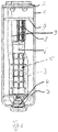
- FIG. 1 shows an exemplary embodiment of a fluid collector, which has a housing 1 and a cover 2, which the housing 1 concludes.
- a fluid collector which has a housing 1 and a cover 2, which the housing 1 concludes.
- openings are provided as an inlet and as an outlet, which allow the inflow and outflow of the refrigerant, wherein the lid 2 otherwise ensures a gas-tight closure of the housing 1.
- the outlet line of the U-shaped suction tube 3 passes through the lid 2 and the second end, which is open to the interior of the collector, and is shielded by a gas filter 8.
- the U-shaped suction tube 3 has in the region of the deflection of a protected by an oil filter 4 opening, which is not shown, which serves for the return of settling at the collector bottom oil in the refrigerant circuit of the air conditioner.
- a dryer 6 is arranged at the top of the oil filter 4.
- a first support means is arranged, which is designed in the embodiment as a support disk 7.
- the support disk 7 further comprises both portions of the U-shaped suction tube 3, which are supported by means of the support disk 7 on the housing wall.
- the gas filter 8, which shields the open end of the suction tube 3 is covered at its upper end by the guide 9, with which it is connected by means of a clip connection.
- the guide 9 separates the refrigerant inflow area from the calmed collecting area. The design of the inflow is essential for a very constant vapor content of the sucked refrigerant responsible.
- the suction pipe 3 of the exemplary embodiment, as well as the housing 1 and optionally the cover 2 made of aluminum or an aluminum alloy. All other components of the fluid collector, for example, from a CO2-resistant polymer, for example Polyamide, manufactured. But also the lid can be made of this plastic.
- the mesh fabric of the filter which is tightly connected to the filter structure during manufacture, has a mesh size of preferably between 20 ⁇ m to 150 ⁇ m.
- the dryer container 6 of the dryer 5 is received, wherein the dryer container 6 in the FIG. 1 is designed as a kind of cage.
- the container or the cage which or which receives the second material, formed by the refrigerant flow-through.
- the container can also be designed as a mesh, woven or nonwoven container or bag.
- the container is formed in such a fine-pored or fine-meshed manner that both the second material itself and also corrosion products of the second material can be retained by the container. This has the effect that the second material essentially can not circulate freely in the refrigerant circuit and also reaction or corrosion products of the second material can not circulate freely in the refrigerant circuit.
- the drying device comprises a housing 1 with an inlet for the refrigerant and with an outlet for the refrigerant, the housing 1 being made of a first material, wherein a second material is provided in the housing, the second material being such is arranged, that it is flowed around by the refrigerant and / or surrounded by the refrigerant.
- the first material is according to the embodiment of FIG. 1 Aluminum or an aluminum alloy.
- the second material is the material which is preferably arranged in the dryer container 6. It is less noble than the first material.
- the first material is aluminum or one In particular, aluminum alloy and the second material is magnesium, calcium, or other hygroscopic material such as alumina, calcia, calcium sulphate, or the like.
- the dryer material is designed as a liquid absorber, which is accommodated in the refrigerant.
Landscapes
- Chemical & Material Sciences (AREA)
- Analytical Chemistry (AREA)
- Chemical Kinetics & Catalysis (AREA)
- Organic Chemistry (AREA)
- Engineering & Computer Science (AREA)
- Inorganic Chemistry (AREA)
- Thermal Sciences (AREA)
- Physics & Mathematics (AREA)
- Mechanical Engineering (AREA)
- General Engineering & Computer Science (AREA)
- Power Engineering (AREA)
- Drying Of Gases (AREA)
- Drying Of Solid Materials (AREA)
Abstract
Description
- Die Erfindung betrifft einen Trockner für ein Kältemittel, insbesondere gemäß dem Oberbegriff von Anspruch 1, und eine Trocknervorrichtung mit einem solchen Trockner.
- Bei Klimaanlagen mit ihren darin eingesetzten Kältemittelkreisläufen wird ein Trockner in einer Trocknervorrichtung eingesetzt, um Wasser aus dem Kältemittel herauszufiltern. Dazu wird bei Kältemittelkreisläufen mit R134a als Kältemittel, welches in der Vergangenheit eingesetzt wurde, Zeolith als Trocknermaterial eingesetzt. Dies ist bei R134a als Kältemittel sehr wirksam. Dabei wird das Zeolith als Trocknermaterial üblicherweise als Granulat in einem von Kältemittel durchströmbaren Behältnis in einem Fluidsammler vorgesehen, so dass das Trocknermaterial das Wasser aus dem flüssigen Kältemittel ausfiltern und aufnehmen kann. Da das Wasserabsorptionsvermögen von Zeolith hoch ist, kann der Partialdruck des Wassers im Kältemittel niedrig gehalten werden. Solche Fluidsammler mit Trockner sind beispielsweise durch die
DE 697 22 215 T2 bekannt geworden. DieDE 10 2010 0040 403 A1 - Auch bei Kältemittelkreisläufen mit CO2 als Kältemittel, welches auch als R744 bekannt ist, wird Zeolith als Trocknermaterial eingesetzt. Dabei wird das Trocknermaterial ebenso in einem Fluidsammler in einem für das Kältemittel durchströmbaren Behältnis aufgenommen, so dass es das Wasser aus dem Kältemittel herausfiltern kann.
- Nun hat sich aber gezeigt, dass Zeolith als Trockner für Kältemittelkreisläufe mit CO2 als Kältemittel nicht so gut geeignet ist, weil dabei das Wasser und auch das Kältemittel CO2 selbst hinsichtlich der Absorption am Zeolith konkurrieren. Dabei sind auch nur sehr hochwertige Zeolithe mit Porendurchmessern von etwa 3 Å geeignet, was die Verwendung solcher Zeolithe auch relativ teuer macht.
- Darüber hinaus ist die Speicherdichte bei Zeolith begrenzt, so dass etwa 50g Zeolith für zu speichernde 8g Wasser benötigt werden. Dabei ist es auch von Bedeutung, Bauraum einzusparen, weil der verfügbare Bauraum insbesondere für kombinierte Fluidsammler mit innerem Wärmeübertrager beispielsweise gemäß
DE 10 2008 028 851 A1 immer weniger Bauraum zur Verfügung bekommt - Es ist daher die Aufgabe der Erfindung, einen Trockner und eine Trocknervorrichtung zu schaffen, welcher bzw. welche bei der Verwendung von CO2 als Kältemittel effektiv trocknen aber dennoch nur einen reduzierten Bauraum benötigen.
- Die erfindungsgemäße Aufgabe zum Trockner wird mit den Merkmalen von Anspruch 1 gelöst.
- Ein Ausführungsbeispiel der Erfindung betrifft einen Trockner zum Trocknen eines Kältemittels in einem Kältemittelkreislauf durch Bindung von Wasser aus dem Kältemittel mittels des Trockners, wobei das Kältemittel CO2 ist, wobei das Wasser durch eine chemische Reaktion durch Stoffumwandlung oder Einlagerung von Kristallwasser dem Kältemittel entzogen wird, wobei der Trockner und dessen im Kältemittelkreislauf auftretende Reaktionsprodukte im Kältemittel unlöslich sind. Dadurch kann das Wasser, das sich im Kältemittel befindet, auf chemischem Wege durch chemische Reaktion umgewandelt oder eingelagert werden, wobei diese chemische Reaktion oder Einlagerung sich nur auf das Wasser bezieht und nicht durch das umgebende CO2 gestört wird.
- Besonders vorteilhaft ist es, wenn der Trockner und dessen im Kältemittelkreislauf auftretenden Reaktionsprodukte auch in Kältemittelöl unlöslich sind. Dadurch können der Trockner und die Reaktionsprodukte ohne Beeinflussung durch das vorhandene Kältemittelöl ausgefiltert werden.
- Auch ist es vorteilhaft, wenn der Trockner ein elektrochemisches Element aus einem ersten Material, insbesondere eines Gehäuses, und einem zweiten Material ist, wobei das zweite Material unedler ist als das erste Material des Gehäuses. Dadurch wird gefördert, dass das Wasser sich an dem unedleren zweiten Material ansammelt bzw. von diesem angesammelt wird und von diesem gebunden wird.
- Weiterhin ist es besonders vorteilhaft, wenn das erste Material Aluminium oder eine Aluminiumlegierung ist und das zweite Material Magnesium oder Calcium ist oder ein hygroskopischer Stoff ist, wie beispielsweise Aluminiumoxid, Calciumoxid, Calciumsulphat oder ähnliches.
- Gemäß eines weiteren Aspekts des Erfindungsgedankens ist es vorteilhaft, wenn der Trockner als flüssiger Absorber ausgebildet ist, welcher in dem Kältemittel aufgenommen ist. Dabei soll die Bindung des Wassers mit dem flüssigen Absorber irreversibel sein, beispielsweise durch eine chemische Reaktion oder eine Komplexbildung. Dadurch kann der flüssige Absorber mit dem Kältemittel in dem Kältemittelkeislauf umgewälzt werden und gleichzeitig das im Kältemittel befindliche Wasser aufnehmen und binden.
- Die Aufgabe zur Trocknungsvorrichtung wird mit den Merkmalen von Anspruch 6 gelöst.
- Ein Ausführungsbeispiel der Erfindung betrifft eine Trocknervorrichtung mit einem Gehäuse mit einem Einlass für ein Kältemittel und mit einem Auslass für das Kältemittel, wobei das Gehäuse aus einem ersten Material besteht, wobei in dem Gehäuse ein zweites Material vorgesehen ist, wobei das zweite Material derart angeordnet ist, dass es von dem Kältemittel umströmbar und/oder von dem Kältemittel umgeben ist. Dadurch wird eine Trocknervorrichtung geschaffen, welche hinsichtlich des Bauraums optimiert ist, weil die Wasseraufnahmefähigkeit bzw. die Wasserfilterfähigkeit deutlich höher ist als bei dem bisher bekannten Zeolith als Trocknermaterial. Dadurch kann der für das Trocknermaterial zu verwendende Bauraum reduziert werden, was auch die gesamte Trocknervorrichtung kleiner bauen lässt.
- Dabei ist es auch vorteilhaft, wenn das zweite Material unedler ist als das erste Material. So wird eine Art Opferanode erzielt, die am unedleren zweiten Material gebildet wird, so dass die beabsichtigte chemische Reaktion an dem zweiten Material stattfindet.
- Auch ist es vorteilhaft, wenn das erste Material Aluminium oder eine Aluminiumlegierung ist und das zweite Material Magnesium, Calcium, oder ein sonstiger hygroskopischer Stoff ist, wie Aluminiumoxid, Calciumoxid, Calciumsulphat oder ähnliches. Dadurch ergibt sich eine gute Wasserfilterung bzw. Wasseraufnahme.
- Besonders vorteilhaft ist es, wenn das zweite Material in einem von Kältemittel durchströmbaren Behältnis aufgenommen ist. Dabei kann das zweite Material als Pulver, als Granulat oder ähnliches ausgebildet sein, welches in dem Behältnis aufgenommen ist.
- Weiterhin ist es auch vorteilhaft, wenn das Behältnis als ein Netz-, Gewebe- oder Vliesbehältnis oder -beutel ausgebildet ist oder es als Käfig ausgebildet ist. So kann das zweite Material sicher aufgenommen werden, ohne dass die Gefahr besteht, dass es weggespült wird.
- Auch ist es vorteilhaft, wenn das Behältnis derart feinporig oder feinmaschig ausgebildet ist, dass Korrosionsprodukte des zweiten Materials von dem Behältnis zurückgehalten werden können.
- Weitere vorteilhafte Ausgestaltungen sind durch die nachfolgende Figurenbeschreibung und durch die Unteransprüche beschrieben.
- Nachstehend wird die Erfindung auf der Grundlage zumindest eines Ausführungsbeispiels anhand der Figuren der Zeichnung näher erläutert. Es zeigen:
- Fig. 1
- eine schematische Ansicht eines Fluidsammler, in welchem eine Trocknungsvorrichtung mit Trockner aufgenommen ist.
- Die
Figur 1 zeigt eine beispielhafte Ausführungsform eines Fluidsammlers, welcher ein Gehäuse 1 und einen Deckel 2 aufweist, welcher das Gehäuse 1 abschließt. In dem Deckel 2 sind Öffnungen als Einlass und als Auslass vorgesehen, welche das Einströmen und das Ausströmen des Kältemittels ermöglichen, wobei der Deckel 2 ansonsten einen gasdichten Verschluss des Gehäuses 1 gewährleistet. - Die Austrittsleitung des U-förmig gestalteten Saugrohrs 3 durchtritt den Deckel 2 und das zweite Ende, welches zum Innenraum des Sammlers hin offen ist, und wird von einem Gasfilter 8 abgeschirmt. Das U-förmig gestaltete Saugrohr 3 weist im Bereich der Umlenkung eine durch einen Ölfilter 4 geschützte Öffnung, die nicht gezeigt ist, auf, welche zur Rückführung von sich am Sammlerboden absetzenden Öl in den Kältemittelkreislauf der Klimaanlage dient.
- An der Oberseite des Ölfilters 4 ist ein Trocknerbehältnis 6 angeordnet. Im Verbindungsbereich des Ölfilters 4 mit dem Trocknerbehältnis 6 ist eine erste Stützeinrichtung angeordnet, welche im Ausführungsbeispiel als Stützscheibe 7 ausgeführt ist. Die Stützscheibe 7 umfasst weiterhin beide Abschnitte des U-förmigen Saugrohrs 3, welche mittels der Stützscheibe 7 an der Gehäusewandung abgestützt werden.
- Der Gasfilter 8, der das offene Ende des Saugrohres 3 abschirmt, ist an seinem oberen Ende von der Leiteinrichtung 9 bedeckt, mit der er mittels einer Clipverbindung verbunden ist. Die Leiteinrichtung 9 trennt den Kältemitteleinströmbereich vom beruhigten Sammelbereich. Die Gestaltung des Einströmbereichs ist wesentlich für einen möglichst konstanten Dampfgehalt des abgesaugten Kältemittels verantwortlich.
- Das Saugrohr 3 der beispielhaften Ausführungsform ist ebenso wie das Gehäuse 1 und gegebenenfalls der Deckel 2 aus Aluminium oder einer Aluminiumlegierung hergestellt. Alle übrigen Bestandteile des Fluidsammlers sind beispielsweise aus einem CO2-beständige Polymer, beispielsweise aus Polyamid, hergestellt. Dabei kann aber auch der Deckel aus diesem Kunststoff hergestellt sein. Das Maschengewebe der Filter, welches bei der Fertigung dicht mit der Filterstruktur verbunden wird, weist eine Maschenweite von vorzugsweise zwischen 20 µm bis 150 µm auf.
- In dem Trocknerbehältnis 6 ist der Trockner 5 aufgenommen, wobei das Trocknerbehältnis 6 in der
Figur 1 als Art Käfig ausgebildet ist. Dabei ist das Behältnis bzw. der Käfig, welches bzw. welcher das zweite Material aufnimmt, von dem Kältemittel durchströmbar ausgebildet. - Alternativ zu dem gezeigten Käfig kann das Behältnis ebenso auch als ein Netz-, Gewebe- oder Vliesbehältnis oder -beutel ausgebildet sein.
- Dabei ist das Behältnis derart feinporig oder feinmaschig ausgebildet, dass sowohl das zweite Material selbst als auch Korrosionsprodukte des zweiten Materials von dem Behältnis zurückgehalten werden können. Dadurch wird bewirkt, dass das zweite Material im Wesentlichen nicht in dem Kältemittelkreislauf frei zirkulieren kann und auch Reaktions- bzw. Korrosionsprodukte des zweiten Materials nicht frei im Kältemittelkreislauf zirkulieren können.
- Gemäß der erfindungsgemäßen Trocknervorrichtung weist die Trocknervorrichtung ein Gehäuse 1 mit einem Einlass für das Kältemittel und mit einem Auslass für das Kältemittel auf, wobei das Gehäuse 1 aus einem ersten Material besteht, wobei in dem Gehäuse ein zweites Material vorgesehen ist, wobei das zweite Material derart angeordnet ist, dass es von dem Kältemittel umströmbar und/oder von dem Kältemittel umgeben ist. Das erste Material ist gemäß des Ausführungsbeispiels der
Figur 1 Aluminium oder eine Aluminiumlegierung. Das zweite Material ist das Material, das vorzugsweise in dem Trocknerbehältnis 6 angeordnet ist. Es ist unedler als das erste Material. Das erste Material ist Aluminium oder eine Aluminiumlegierung und das zweite Material ist insbesondere Magnesium, Calcium, oder ein sonstiger hygroskopischer Stoff, wie beispielsweise Aluminiumoxid, Calciumoxid, calciumsulphat oder ähnliches. - In einer alternativen Ausführungsform ist das Trocknermaterial als flüssiger Absorber ausgebildet, welcher in dem Kältemittel aufgenommen ist.
Claims (11)
- Trockner (5) zum Trocknen eines Kältemittels in einem Kältemittelkreislauf durch Bindung von Wasser aus dem Kältemittel mittels des Trockners (5), wobei das Kältemittel CO2 ist, dadurch gekennzeichnet, dass das Wasser durch eine chemische Reaktion durch Stoffumwandlung oder Einlagerung von Kristallwasser dem Kältemittel entzogen wird, wobei der Trockner (5) und dessen im Kältemittelkreislauf auftretende Reaktionsprodukte im Kältemittel unlöslich sind.
- Trockner (5) nach Anspruch 1, dadurch gekennzeichnet, dass der Trockner (5) und dessen im Kältemittelkreislauf auftretenden Reaktionsprodukte auch in Kältemittelöl unlöslich sind.
- Trockner (5) nach Anspruch 1 oder 2, dadurch gekennzeichnet, dass der Trockner (5) ein elektrochemisches Element aus einem ersten Material, insbesondere eines Gehäuses (1), und einem zweiten Material ist, wobei das zweite Material unedler ist als das erste Material.
- Trockner (5) nach Anspruch 3, dadurch gekennzeichnet, dass das erste Material Aluminium oder eine Aluminiumlegierung ist und das zweite Material Magnesium oder Calcium oder ein hygroskopischer Stoff ist, wie Aluminiumoxid, Calciumoxid, Calciumsulphat oder ähnliches.
- Trockner (5) nach Anspruch 1 oder 2, dadurch gekennzeichnet, dass der Trockner (5) als flüssiger Absorber ausgebildet ist, welcher in dem Kältemittel aufgenommen ist.
- Trocknervorrichtung mit einem Gehäuse (1) mit einem Einlass für ein Kältemittel und mit einem Auslass für das Kältemittel, wobei das Gehäuse (1) aus einem ersten Material besteht, wobei in dem Gehäuse (1) ein zweites Material angeordnet ist, wobei das zweite Material derart angeordnet ist, dass es von dem Kältemittel umströmbar und/oder von dem Kältemittel umgeben ist.
- Trocknervorrichtung nach Anspruch 6, dadurch gekennzeichnet, dass das zweite Material unedler ist als das erste Material.
- Trocknervorrichtung nach Anspruch 7, dadurch gekennzeichnet, dass das erste Material Aluminium oder eine Aluminiumlegierung ist und das zweite Material Magnesium, Calcium, oder ein sonstiger hygroskopischer Stoff ist, wie Aluminiumoxid, Calciumoxid, Calciumsulphat oder ähnliches.
- Trocknervorrichtung nach Anspruch 6, 7 oder 8, dadurch gekennzeichnet, dass das zweite Material in einem von Kältemittel durchströmbaren Trocknerbehältnis (6) aufgenommen ist.
- Trocknervorrichtung nach Anspruch 9, dadurch gekennzeichnet, dass das Trocknerbehältnis (6) als ein Netz-, Gewebe- oder Vliesbehältnis oder -beutel ausgebildet ist oder es als Käfig ausgebildet ist.
- Trocknervorrichtung nach Anspruch 10, dadurch gekennzeichnet, dass das Trocknerbehältnis (6) derart feinporig oder feinmaschig ausgebildet ist, dass Korrosionsprodukte des zweiten Materials von dem Trocknerbehältnis (6) zurückgehalten werden können.
Applications Claiming Priority (1)
| Application Number | Priority Date | Filing Date | Title |
|---|---|---|---|
| DE102015203601.4A DE102015203601A1 (de) | 2015-02-27 | 2015-02-27 | Trockner |
Publications (2)
| Publication Number | Publication Date |
|---|---|
| EP3062043A2 true EP3062043A2 (de) | 2016-08-31 |
| EP3062043A3 EP3062043A3 (de) | 2017-03-01 |
Family
ID=55484827
Family Applications (1)
| Application Number | Title | Priority Date | Filing Date |
|---|---|---|---|
| EP16157375.3A Withdrawn EP3062043A3 (de) | 2015-02-27 | 2016-02-25 | Trockner |
Country Status (2)
| Country | Link |
|---|---|
| EP (1) | EP3062043A3 (de) |
| DE (1) | DE102015203601A1 (de) |
Citations (3)
| Publication number | Priority date | Publication date | Assignee | Title |
|---|---|---|---|---|
| DE69722215T2 (de) | 1996-07-31 | 2003-11-27 | Parker-Hannifin Corp., Cleveland | Sammler/trockner und zusammenbauverfahren |
| DE102008028851A1 (de) | 2008-06-19 | 2009-12-24 | Behr Gmbh & Co. Kg | Verbindung zwischen einem Rohrende und einem Kupplungsteil sowie Verfahren zur Herstellung der Verbindung |
| DE102010040403A1 (de) | 2010-09-08 | 2012-03-08 | Bayerische Motoren Werke Aktiengesellschaft | Vorrichtung zur Kältemittel-Trocknung |
Family Cites Families (7)
| Publication number | Priority date | Publication date | Assignee | Title |
|---|---|---|---|---|
| US1809833A (en) * | 1926-06-17 | 1931-06-16 | Chicago Pneumatic Tool Co | Method of and means for stabilizing refrigerants |
| US2225990A (en) * | 1937-12-22 | 1940-12-24 | Guy J Henry | Dehydrator |
| DD143862A1 (de) * | 1979-05-07 | 1980-09-17 | Christian Petermann | Verfahren und anordnung zur entfernung von feuchtigkeit aus verfluessigbaren gasen,insbesondere in kaeltemittelsystemen |
| DE19905378C1 (de) * | 1999-02-10 | 2000-08-03 | Hansa Metallwerke Ag | Filtertrockner, insbesondere Groß-Filtertrockner, für stationäre Kälteanlagen sowie Filtertrocknerkartusche zur Verwendung bei einem solchen Filtertrockner |
| JP2004309127A (ja) * | 2003-04-03 | 2004-11-04 | Behr Gmbh & Co Kg | 冷媒凝縮装置 |
| DE502005002246D1 (de) * | 2005-10-12 | 2008-01-24 | Coexal Gmbh | verfahren zur Herstellung einer Vorrichtung zum Sammeln und Trocknen eines Kühlmittels in einer Klimaanlage |
| DE102007018427A1 (de) * | 2007-04-17 | 2008-10-23 | Behr Gmbh & Co. Kg | Fluidsammler |
-
2015
- 2015-02-27 DE DE102015203601.4A patent/DE102015203601A1/de not_active Withdrawn
-
2016
- 2016-02-25 EP EP16157375.3A patent/EP3062043A3/de not_active Withdrawn
Patent Citations (3)
| Publication number | Priority date | Publication date | Assignee | Title |
|---|---|---|---|---|
| DE69722215T2 (de) | 1996-07-31 | 2003-11-27 | Parker-Hannifin Corp., Cleveland | Sammler/trockner und zusammenbauverfahren |
| DE102008028851A1 (de) | 2008-06-19 | 2009-12-24 | Behr Gmbh & Co. Kg | Verbindung zwischen einem Rohrende und einem Kupplungsteil sowie Verfahren zur Herstellung der Verbindung |
| DE102010040403A1 (de) | 2010-09-08 | 2012-03-08 | Bayerische Motoren Werke Aktiengesellschaft | Vorrichtung zur Kältemittel-Trocknung |
Also Published As
| Publication number | Publication date |
|---|---|
| EP3062043A3 (de) | 2017-03-01 |
| DE102015203601A1 (de) | 2016-09-01 |
Similar Documents
| Publication | Publication Date | Title |
|---|---|---|
| EP0669506B2 (de) | Kondensator für eine Klimaanlage eines Fahrzeuges | |
| DE102009030897B4 (de) | Lufttrocknerpatrone für eine Druckluftaufbereitungsanlage eines Fahrzeugs und Druckluftaufbereitungsanlage für ein Fahrzeug mit einer entsprechenden Lufttrocknerpatrone. | |
| DE102011116520A1 (de) | Luftfilterpatrone zur Druckluftaufbereitung für eine Druckluftaufbereitungsanlage | |
| DE2209883B2 (de) | Flüssigkeits-Gas-Trennvorrichtung für eine Kälteanlage | |
| DE4319293A1 (de) | Klimaanlage für ein Fahrzeug | |
| DE2922237A1 (de) | Gasfilter | |
| DE102010053758A1 (de) | Filterelement und Gehäuse zur Aufnahme des Filterelements | |
| DE69405192T2 (de) | Sammel- und Entwässerungsbehälter mit Bodenablass | |
| DE102019122032A1 (de) | Trocknerkartusche, Trocknungssystem und Verwendung hiervon | |
| DE102012105137A1 (de) | Lufttrocknerpatrone und Verfahren zur Herstellung einer Lufttrocknerpatrone | |
| DE112018006434T5 (de) | Lufttrocknerspülluftreinigungsvorrichtung mit strukturierten absorbierenden partikeln | |
| DE102005021787A1 (de) | Vorrichtung zur Behandlung des Kältemittels | |
| DE60017629T2 (de) | Trocknungssammler für Kälteanlagen und Verfahren zum Zusammenbauen eines solchen Sammlers | |
| DE102007009760A1 (de) | Trockner-Filter-Einheit für Kältemittelkreisläufe | |
| WO2017148790A1 (de) | Filtermaterial für einen filtereinsatz eines kraftstofffilters, filtereinsatz und kraftstofffilter | |
| DE69206891T2 (de) | Filter | |
| EP4098347B1 (de) | Filtervorrichtung | |
| DE102015203601A1 (de) | Trockner | |
| DE102017209039A1 (de) | Flüssigkeitsfilter | |
| DE102010048867A1 (de) | Sorptionsvorrichtung zur Klimatisierung eines Fahrzeugs und Verfahren zum Betrieb einer Sorptionsvorrichtung | |
| DE102007028591A1 (de) | Akkumulator, insbesondere für eine Kraftfahrzeug- Klimaanlage | |
| WO2019042823A1 (de) | Koaleszerstufe eines filtereinsatzes eines kraftstofffilters, filtereinsatz und kraftstofffilter | |
| DE3020034C2 (de) | Sorptionskörper | |
| DE102005009191B3 (de) | Kältemittelsammler mit Filter/Trockner-Einheit | |
| DE102005024158C5 (de) | Trockner für ein Kühlmedium in einem Kühlmedienkreislauf, insbesondere für eine Klimaanlage eines Fahrzeugs |
Legal Events
| Date | Code | Title | Description |
|---|---|---|---|
| PUAI | Public reference made under article 153(3) epc to a published international application that has entered the european phase |
Free format text: ORIGINAL CODE: 0009012 |
|
| AK | Designated contracting states |
Kind code of ref document: A2 Designated state(s): AL AT BE BG CH CY CZ DE DK EE ES FI FR GB GR HR HU IE IS IT LI LT LU LV MC MK MT NL NO PL PT RO RS SE SI SK SM TR |
|
| AX | Request for extension of the european patent |
Extension state: BA ME |
|
| PUAL | Search report despatched |
Free format text: ORIGINAL CODE: 0009013 |
|
| AK | Designated contracting states |
Kind code of ref document: A3 Designated state(s): AL AT BE BG CH CY CZ DE DK EE ES FI FR GB GR HR HU IE IS IT LI LT LU LV MC MK MT NL NO PL PT RO RS SE SI SK SM TR |
|
| AX | Request for extension of the european patent |
Extension state: BA ME |
|
| RIC1 | Information provided on ipc code assigned before grant |
Ipc: F25B 43/00 20060101AFI20170125BHEP Ipc: F25B 9/00 20060101ALI20170125BHEP Ipc: B01J 20/00 20060101ALI20170125BHEP |
|
| 17P | Request for examination filed |
Effective date: 20170901 |
|
| RBV | Designated contracting states (corrected) |
Designated state(s): AL AT BE BG CH CY CZ DE DK EE ES FI FR GB GR HR HU IE IS IT LI LT LU LV MC MK MT NL NO PL PT RO RS SE SI SK SM TR |
|
| 17Q | First examination report despatched |
Effective date: 20190528 |
|
| STAA | Information on the status of an ep patent application or granted ep patent |
Free format text: STATUS: THE APPLICATION IS DEEMED TO BE WITHDRAWN |
|
| 18D | Application deemed to be withdrawn |
Effective date: 20200901 |