EP3061583B1 - Herstellungsverfahren einer wabenstruktur und wabenformkörper - Google Patents
Herstellungsverfahren einer wabenstruktur und wabenformkörper Download PDFInfo
- Publication number
- EP3061583B1 EP3061583B1 EP16155255.9A EP16155255A EP3061583B1 EP 3061583 B1 EP3061583 B1 EP 3061583B1 EP 16155255 A EP16155255 A EP 16155255A EP 3061583 B1 EP3061583 B1 EP 3061583B1
- Authority
- EP
- European Patent Office
- Prior art keywords
- face
- formed body
- convex
- honeycomb
- convex end
- Prior art date
- Legal status (The legal status is an assumption and is not a legal conclusion. Google has not performed a legal analysis and makes no representation as to the accuracy of the status listed.)
- Active
Links
Images


Classifications
-
- B—PERFORMING OPERATIONS; TRANSPORTING
- B28—WORKING CEMENT, CLAY, OR STONE
- B28B—SHAPING CLAY OR OTHER CERAMIC COMPOSITIONS; SHAPING SLAG; SHAPING MIXTURES CONTAINING CEMENTITIOUS MATERIAL, e.g. PLASTER
- B28B11/00—Apparatus or processes for treating or working the shaped or preshaped articles
- B28B11/12—Apparatus or processes for treating or working the shaped or preshaped articles for removing parts of the articles by cutting
-
- C—CHEMISTRY; METALLURGY
- C04—CEMENTS; CONCRETE; ARTIFICIAL STONE; CERAMICS; REFRACTORIES
- C04B—LIME, MAGNESIA; SLAG; CEMENTS; COMPOSITIONS THEREOF, e.g. MORTARS, CONCRETE OR LIKE BUILDING MATERIALS; ARTIFICIAL STONE; CERAMICS; REFRACTORIES; TREATMENT OF NATURAL STONE
- C04B38/00—Porous mortars, concrete, artificial stone or ceramic ware; Preparation thereof
- C04B38/0006—Honeycomb structures
-
- B—PERFORMING OPERATIONS; TRANSPORTING
- B01—PHYSICAL OR CHEMICAL PROCESSES OR APPARATUS IN GENERAL
- B01D—SEPARATION
- B01D46/00—Filters or filtering processes specially modified for separating dispersed particles from gases or vapours
- B01D46/0001—Making filtering elements
-
- B—PERFORMING OPERATIONS; TRANSPORTING
- B28—WORKING CEMENT, CLAY, OR STONE
- B28B—SHAPING CLAY OR OTHER CERAMIC COMPOSITIONS; SHAPING SLAG; SHAPING MIXTURES CONTAINING CEMENTITIOUS MATERIAL, e.g. PLASTER
- B28B11/00—Apparatus or processes for treating or working the shaped or preshaped articles
- B28B11/24—Apparatus or processes for treating or working the shaped or preshaped articles for curing, setting or hardening
- B28B11/243—Setting, e.g. drying, dehydrating or firing ceramic articles
-
- B—PERFORMING OPERATIONS; TRANSPORTING
- B28—WORKING CEMENT, CLAY, OR STONE
- B28B—SHAPING CLAY OR OTHER CERAMIC COMPOSITIONS; SHAPING SLAG; SHAPING MIXTURES CONTAINING CEMENTITIOUS MATERIAL, e.g. PLASTER
- B28B11/00—Apparatus or processes for treating or working the shaped or preshaped articles
- B28B11/24—Apparatus or processes for treating or working the shaped or preshaped articles for curing, setting or hardening
- B28B11/248—Supports for drying
-
- C—CHEMISTRY; METALLURGY
- C04—CEMENTS; CONCRETE; ARTIFICIAL STONE; CERAMICS; REFRACTORIES
- C04B—LIME, MAGNESIA; SLAG; CEMENTS; COMPOSITIONS THEREOF, e.g. MORTARS, CONCRETE OR LIKE BUILDING MATERIALS; ARTIFICIAL STONE; CERAMICS; REFRACTORIES; TREATMENT OF NATURAL STONE
- C04B33/00—Clay-wares
- C04B33/32—Burning methods
-
- B—PERFORMING OPERATIONS; TRANSPORTING
- B01—PHYSICAL OR CHEMICAL PROCESSES OR APPARATUS IN GENERAL
- B01D—SEPARATION
- B01D46/00—Filters or filtering processes specially modified for separating dispersed particles from gases or vapours
- B01D46/24—Particle separators, e.g. dust precipitators, using rigid hollow filter bodies
- B01D46/2403—Particle separators, e.g. dust precipitators, using rigid hollow filter bodies characterised by the physical shape or structure of the filtering element
- B01D46/2418—Honeycomb filters
- B01D46/2451—Honeycomb filters characterized by the geometrical structure, shape, pattern or configuration or parameters related to the geometry of the structure
- B01D46/2482—Thickness, height, width, length or diameter
-
- B—PERFORMING OPERATIONS; TRANSPORTING
- B01—PHYSICAL OR CHEMICAL PROCESSES OR APPARATUS IN GENERAL
- B01D—SEPARATION
- B01D46/00—Filters or filtering processes specially modified for separating dispersed particles from gases or vapours
- B01D46/24—Particle separators, e.g. dust precipitators, using rigid hollow filter bodies
- B01D46/2403—Particle separators, e.g. dust precipitators, using rigid hollow filter bodies characterised by the physical shape or structure of the filtering element
- B01D46/2418—Honeycomb filters
- B01D46/2451—Honeycomb filters characterized by the geometrical structure, shape, pattern or configuration or parameters related to the geometry of the structure
- B01D46/2484—Cell density, area or aspect ratio
-
- B—PERFORMING OPERATIONS; TRANSPORTING
- B28—WORKING CEMENT, CLAY, OR STONE
- B28B—SHAPING CLAY OR OTHER CERAMIC COMPOSITIONS; SHAPING SLAG; SHAPING MIXTURES CONTAINING CEMENTITIOUS MATERIAL, e.g. PLASTER
- B28B3/00—Producing shaped articles from the material by using presses; Presses specially adapted therefor
- B28B3/20—Producing shaped articles from the material by using presses; Presses specially adapted therefor wherein the material is extruded
- B28B2003/203—Producing shaped articles from the material by using presses; Presses specially adapted therefor wherein the material is extruded for multi-channelled structures, e.g. honeycomb structures
Definitions
- the present invention relates a manufacturing method of a honeycomb structure, and a honeycomb formed body. More particularly, it relates to a manufacturing method of a honeycomb structure in which an unfired honeycomb formed body extruded by using an extruder is fired in a firing furnace, and a honeycomb formed body.
- a honeycomb structure made of ceramics has broadly been used in a use application such as a car exhaust gas purifying catalyst carrier, a diesel particulate removing filter, or a heat reservoir for a burning device.
- the honeycomb structure made of the ceramics (hereinafter simply referred to as "the honeycomb structure") is manufactured by preparing a forming raw material (a kneaded material), forming a honeycomb formed body by extruding the material into a desirable honeycomb shape by use of an extruder, followed by raw cutting, drying and finish-cutting, and then subjecting the honeycomb formed body to a firing step of firing the honeycomb formed body at a high temperature.
- the honeycomb formed body is mounted on a shelf plate in a state where one end face of the honeycomb formed body is directed downward, and the honeycomb formed body is thrown together with the shelf plate into a firing furnace.
- a firing support plate called "a setter” is usually interposed between the shelf plate and the honeycomb formed body.
- a setter for example, a sliced piece of the honeycomb structure obtained by firing the honeycomb formed body is used, and the setter is repeatedly usable.
- a press-molded and fired ceramic raw material called "a pressed setter”
- Such setters are generically called “a firing setter”.
- a firing raw setter obtained by slicing an unfired honeycomb formed body made of the same material as in the honeycomb formed body is used in the firing step (e.g., see Patent Document 2).
- the extruded body before fired is defined as “the honeycomb formed body”
- the fired honeycomb formed body is defined as "the honeycomb structure”.
- US 2006/165956 describes a manufacturing method of a ceramic honeycomb structure body which has extrusion molding with ceramic raw materials in a honeycomb structure, cutting to cut a molded one into plural mold bodies, each mold body having an outer peripheral skin part and plural cell walls.
- the manufacturing method performs a drying process of drying each mold body, a chamfering process of chamfer an edge of a corner of the mold body, and a burning process of burning the mold body in order to form the ceramic honeycomb structure body.
- WO 2014/038485 describes a honeycomb structure production method with a sintering step in which a honeycomb structure is obtained by sintering a green compact having a plurality of flow paths that are parallel to each other, said flow paths being partitioned by partitions.
- the green compact is positioned on a support member.
- the support member has a support section and a support section that is laminated on the support section.
- the support section supports one end surface of the green compact. In a direction which is perpendicular to the lamination direction of the support section and the support section, the diameter of the support section is smaller than the diameter of the support section.
- US 2012/013052 describes a process for firing a porous ceramic structure of the honeycomb type on a firing setter, said structure comprising a plurality of longitudinal through-channels terminating in two ends of the structure, the end bearing on the setter having a maximum width Ls before firing, in a longitudinal sectional plane passing through the principal axis of the structure, said process being characterized in that the setter has, in said longitudinal sectional plane: a first level corresponding to a first face of the setter serving as bearing surface for the structure to be fired, said level having a maximum width L 1 ; a second level, spaced away from said first face of the setter by a thickness E 1-2 , said second level having a maximum width L2; the width L 1 being equal to or greater than Ls; and the width L 2 being less than L 1 and also to the setter as described above.
- An extruded honeycomb formed body performs a firing shrinkage along a cell longitudinal direction and a direction perpendicular to the cell longitudinal direction in a firing step. Consequently, in a case where the honeycomb formed body is mounted on the above-mentioned firing setter and thrown into a firing furnace, a shift occurs between an upper surface of the firing setter and a lower end face of the honeycomb formed body due to the firing shrinkage of the honeycomb formed body, and defects such as deformation and crack of cell partition walls might be generated in a lower end face of a honeycomb structure which comes in contact with the firing setter.
- the raw setter is made of the same material as in the honeycomb formed body as a firing object, and hence a firing shrinkage difference between the honeycomb formed body and the raw setter during the firing is not made. Therefore, the raw setter can perform a firing shrinkage along the cell longitudinal direction and a cross-sectional direction perpendicular to the cell longitudinal direction at the same timing and the same ratio as in the honeycomb formed body. Consequently, it is possible to eliminate a disadvantage in a case where the firing setter is used.
- the raw setter receives restriction of a shelf plate and can only isotropically perform the firing shrinkage, and the firing shrinkage difference might be made between the raw setter and the honeycomb formed body to be mounted on the raw setter.
- the cell partition walls of the honeycomb formed body might be deformed on the side of a raw setter mounting surface, or a shape accuracy (e.g., a roundness) of the honeycomb formed body might be adversely affected.
- the raw setter is not repeatedly usable, and also becomes a factor to increase firing cost in the firing of the honeycomb formed body.
- the present invention has been developed in view of the above situation of the conventional technology, and an object thereof is to provide a manufacturing method of a honeycomb structure in which a setter is not used and hence it is possible to alleviate generation of a defect in an end face of the honeycomb structure and to suppress firing cost, and a honeycomb formed body for use in the manufacturing method.
- a manufacturing method of a honeycomb structure which achieves the above object, and a honeycomb formed body.
- the honeycomb structure suitably holding cell partition walls of an end face and a shape accuracy can be manufactured without using a setter.
- a honeycomb formed body of the present invention is usable in the above manufacturing method.
- a honeycomb formed body 1 of one embodiment of the present invention has a convex end portion 3 in the form of a thin disc schematically possessing a round pillar shape as a whole, projecting from the vicinity of a center of one end face 2a along a central axis direction X (see Fig. 1 ) and including a planar convex end face 3a and a convex peripheral surface 3b perpendicular to the convex end face 3a.
- the honeycomb formed body 1 is processed so that its cross section has a convex shape in which the vicinity of the center of the one end face 2a swells.
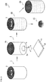
- a manufacturing method 100 of a honeycomb structure in which the honeycomb formed body 1 is used will be described with reference to Fig. 3 . It is to be noted that in Figs. 1 to 5 , cells and partition walls which appear in an end face of the honeycomb formed body 1 are partially omitted from the drawings.
- the honeycomb formed body 1 is obtained by preparing a forming raw material (a kneaded material) and extruding the material into a desirable shape by use of an extruder, and after the body is extruded by the extruder, the body is formed on the basis of the round pillar-shaped honeycomb formed body 1 cut into a predetermined length (raw cutting), dried and finish-cut (a forming step).
- the one end face 2a of the round pillar-shaped honeycomb formed body 1 formed by the forming step is to grind and processed into a round shape with a cup type grinding wheel or the like, and there is formed the convex end portion 3 including the convex end face 3a in which the vicinity of a center projects from a corner portion 4 of the one end face 2a and which is parallel to an annular flat surface portion 2c formed in the one end face 2a (a convex end portion forming step).
- Fig. 1 shows a state where the one end face 2a is directed upward, for simplification of the drawing.
- Fig. 3 similarly shows a state where the one end face 2a is directed upward, except a view (the second from the left) showing that the honeycomb formed body 1 is to be mounted on a shelf plate 10.
- the honeycomb formed body 1 has a plurality of cells 5 which extend from the one end face 2a to the other end face 2b and which become through channels for a fluid and has latticed partition walls 6 defining the cells 5.
- an area ratio R (R2/R1 ⁇ 100) of an area R2 of the convex end face 3a of the convex end portion 3 to a sectional area R1 of the honeycomb formed body 1 is set to a range of 15 to 30% (see Fig. 2).
- Fig. 2 shows the sectional area R1 and the area R2 which are shown in diameter portions of the honeycomb formed body 1 and the convex end face 3a, respectively.
- the area ratio R is set to the above range.
- a convex end portion height H (corresponding to a height of the convex peripheral surface 3b) from the corner portion 4 of the one end face 2a to the convex end face 3a of the convex end portion 3, but the height can be set to, e.g., a range of 0.3 to 3 mm.
- the convex end portion height H is set to the range of 0.3 to 3 mm.
- the honeycomb formed body 1 formed through the forming step and the convex end portion forming step are mounted on the shelf plate surface 11 of the shelf plate 10 by directing the one end face 2a downward (the mounting step).
- the clearance space 7 is made, as much as a distance corresponding to the convex end portion height H of the convex end portion 3, between the corner portion 4 of the one end face 2a and the shelf plate surface 11 by the convex end portion 3 formed on the honeycomb formed body 1. That is, in a case where the honeycomb formed body 1 is mounted on the shelf plate 10, the one end face 2a does not entirely abut on the shelf plate surface 11.
- a firing step is performed in a state where the honeycomb formed body 1 is mounted on the shelf plate 10.
- the shelf plate 10 for use is made of a heat resistant ceramic material, and does not cause the firing shrinkage even at a high firing temperature. Additionally, an area of the shelf plate surface 11 of the shelf plate 10 is formed to be larger than that of the one end face 2a of the honeycomb formed body 1. Therefore, the honeycomb formed body 1 mounted on the shelf plate 10 does not project from the shelf plate 10.
- the honeycomb formed body 1 has the convex end portion 3 in the vicinity of its center and is therefore disposed in a state where the vicinity of the corner portion 4 of the one end face 2a is floated above the shelf plate surface 11 of the shelf plate 10. That is, the vicinity of the corner portion 4 of the one end face 2a is not influenced from the outside.
- the honeycomb formed body 1 mounted on the shelf plate 10 is thrown into a firing furnace, and firing is performed at a predetermined firing temperature for predetermined firing time (the firing step). In consequence, the firing of the honeycomb formed body 1 is completed, and a honeycomb fired body 20 is formed.
- the firing step a ceramic raw material is sintered, and firing shrinkages are generated along a longitudinal direction (corresponding to the central axis direction X) of the honeycomb formed body 1 and a cross-section perpendicular to the longitudinal direction, respectively.
- the vicinity of the corner portion 4 of the one end face 2a of the honeycomb formed body 1 which is present at a position floated from the shelf plate surface 11 does not directly come in contact with the shelf plate 10 as described above, and there are not any factors that disturb the firing shrinkages.
- the other end face 2b becomes an upper surface during the firing and, therefore, is not restricted, and there are not any factors that disturb the firing shrinkages.
- an isotropic firing shrinkage is performed along the longitudinal direction and the cross section perpendicular to this longitudinal direction. That is, when the area where the honeycomb formed body 1 comes in contact with the shelf plate 10 is decreased as much as possible, a disadvantage such as deformation of the latticed partition walls 6 defining the cells 5 is generated in the convex end face 3a of the one end face 2a, but is not generated in the vicinity of the corner portion 4. As a result, a defect due to the deformation of the partition walls 6 or partition wall cracks, a roundness defect or the like is not caused in the one end face 2a of the honeycomb fired body 20 after the firing is performed. In consequence, it is possible to eliminate a problem such as the defect in the firing step, and it is possible to form the honeycomb fired body 20 having high quality such as high shape stability.
- the convex end portion 3 in the form of a disc remains to be formed in the vicinity of the center of the one end face 2a (see Fig. 3 ). Therefore, a rotating cup type grinding wheel (not shown) is gradually brought close to the honeycomb fired body from a position facing the one end face 2a, while rotating the honeycomb fired body 20 based on the central axis direction X as a rotation axis (the end face grinding step). Consequently, the convex end portion 3 is gradually cut off and removed. In consequence, manufacturing of a round pillar-shaped honeycomb structure 30 is completed.
- Fig. 3 schematically shows a ground and removed portion 21 constituted of the convex end portion 3 cut off by the cup type grinding wheel.
- the end face 2a is preferably ground as much as the height of the convex end portion 3 or more.
- a depth of a disadvantage such as the deformation of the partition walls 6 which is generated in the convex end face 3a is usually about 0.5 mm, and hence for the purpose of removing the disadvantage of the end face 2a, it is necessary to grind the end face as much as 0.5 mm or more.
- a maximum height of the convex end face 3a is 3 mm, and hence the end face does not have to be ground as much as 3 mm or more.
- a honeycomb formed body 40 having a constitution shown in Fig. 4 can be illustrated.
- Fig. 4 is a perspective view showing a schematic constitution of the honeycomb formed body 40.
- the honeycomb formed body 40 is formed so that its cross section of a convex end portion 42 formed on one end face 41 of the honeycomb formed body 40 possesses a tapered shape. That is, a corner portion 43 of the one end face 41 is chamfered in an oblique direction, and has a chamfered portion 44 so that a diameter of a convex end face 42a is smaller than an outer diameter of the honeycomb formed body 40.
- a clearance space 7 is formed at an angle ⁇ to be formed between the chamfered portion 44 and a shelf plate surface 11.
- angle ⁇ to be formed is set to a range of 0.5 to 5°.
- the chamfered portion 44 of the convex end portion 42 of the honeycomb formed body 40 does not directly come in contact with the shelf plate 10, and there are not any factors that disturb a firing shrinkage during a firing step.
- an isotropic firing shrinkage is performed along a longitudinal direction and a cross section perpendicular to this longitudinal direction.
- an area where the honeycomb formed body 40 comes in contact with the shelf plate 10 is decreased as much as possible, and the angle ⁇ to be formed between the chamfered portion 44 and the shelf plate surface 11 is defined, whereby the honeycomb formed body 40 can maintain a restoring force even when the honeycomb formed body swings on the shelf plate 10 due to a vibration during the firing.
- a disadvantage such as deformation of latticed partition walls 6 defining cells 5 is not generated.
- a defect due to the deformation of the partition walls, a defect due to partition wall cracks, a roundness defect or the like is not generated in one end face of a honeycomb fired body after the honeycomb formed body is fired.
- Fig. 5 is a partially enlarged cross-sectional view showing a schematic constitution of a honeycomb formed body 50 of still another example constitution which is mounted on a shelf plate.
- a convex end portion 52 formed on one end face 51 is constituted of a combination of the shape of the convex end portion 3 of the honeycomb formed body 1 mentioned above and the shape of the convex end portion 42 of the honeycomb formed body 40 of the other example constitution.
- the honeycomb formed body 50 has a chamfered portion 54 formed by chamfering the vicinity of the convex end face 52a of the convex end portion 52 in an oblique direction toward a corner portion 53 and having a cross section possessing a tapered shape in which a diameter of the convex end face 52a is smaller than an outer diameter of the honeycomb formed body 50, and a flat surface portion 55 which is bent from one end 54a of the chamfered portion to become parallel to the convex end face 52a.
- a clearance space 7 is formed at an angle ⁇ to be formed between the chamfered portion 54 and a shelf plate surface 11, and surrounded from the upside by the flat surface portion 55.
- the present invention is effectively applied to an integrated product of a honeycomb structure whose circumference is not processed, and is especially noticeably effective in a thin wall product (e.g., a partition wall thickness is 0.15 mm or less) in which cell partition walls are easy to be deformed.
- a thin wall product e.g., a partition wall thickness is 0.15 mm or less
- the present invention is also applicable to a circumference processed product or a honeycomb structure in which cell partition walls are comparatively thick.
- honeycomb formed body of the present invention and the manufacturing method of the honeycomb structure in which this honeycomb formed body is used will be described on the basis of examples mentioned below, but the honeycomb formed body of the present invention and the manufacturing method of the honeycomb structure are not limited to these embodiments.
- honeycomb formed bodies each of which had a convex end portion in one end face and in each of which an area ratio R and an angle ⁇ to be formed between a shelf plate surface and a chamfered portion matched the above ranges, respectively, by forming steps and convex end portion forming steps in which the same kneaded material was used and forming conditions and the other conditions were constant (Examples 1 to 12).
- honeycomb formed bodies were prepared in each of which an area ratio R in the above parameters departed from the above range (Comparative Examples 1 to 8) (see Table 1). It is to be noted that in Table 1, when the angle ⁇ to be formed is 90°, there is indicated a honeycomb formed body which does not have a chamfered portion and has a peripheral surface at right angles to a convex end face.
- each prepared honeycomb formed body which had the convex end portion was directed downward, and the honeycomb formed body was directly mounted on a shelf plate surface of a shelf plate made of a ceramic material.
- a raw setter was interposed between a shelf plate surface and a honeycomb formed body.
- a shelf plate and the honeycomb formed body were thrown into a firing furnace.
- respective firing conditions such as firing time and firing temperature, the same conditions were used in Examples 1 to 12 and Comparative Examples 1 to 8.
- a flatness when the honeycomb formed body was mounted on the shelf plate was set to 0.2 in each of Examples 1 to 12 and Comparative Examples 1 to 8.
- the flatness is a difference between a maximum value and a minimum value, when one end face of a honeycomb formed body is directed downward, the honeycomb formed body is mounted on a flat plate and a height of the end face to the flat plate is measured in a vertical direction to the flat plate.
- a roundness of each of the end face of the honeycomb formed body before fired and an end face of the honeycomb structure after the honeycomb formed body was fired was calculated, and a difference "between the roundness of the honeycomb formed body before fired and the roundness of the honeycomb structure after the honeycomb formed body was fired" was evaluated.
- the roundness represents a size of a difference (a deviation) from a geometric circle of a round body, and is indicated by a difference between a maximum diameter and a minimum diameter.
- maximum outer diameters and minimum outer diameters of the honeycomb formed body and the honeycomb structure are measured with a dimension measuring meter (a laser displacement meter), and a value of the roundness is calculated.
- a shape of the end face of the honeycomb structure was visually confirmed, and presence/absence of partition wall crack and presence/absence of partition wall deformation generated in the end face of the honeycomb structure in the case of the firing shrinkage were visually judged, respectively.
- a case where the crack or the deformation was not recognized was defined as a suitable state and evaluated as "A”
- a case where a deformation amount was small was defined as an allowable state and evaluated as "B”
- a case where noticeable deformation was recognized and was out of an allowable range was evaluated as "C”.
- three stages of evaluations were carried out. According to such evaluation items, it is possible to grasp a correlation between the honeycomb formed body of the present invention in a case where the honeycomb formed body is directly mounted on the shelf plate and the partition wall crack or the partition wall deformation.
- Table 1 mentioned below shows a conclusion of an area ratio R of a convex end face to an outer diameter of a honeycomb formed body of each of Examples 1 to 12 and Comparative Examples 1 to 8, an angle ⁇ to be formed with a shelf plate surface, a flatness, a lattice direction of partition walls, and each evaluation item to each obtained honeycomb structure.
- the honeycomb structure of each of the examples and comparative examples for use in evaluation has a round pillar shape, a diameter of 118 mm, a length of 152 mm, a partition wall thickness of 0.076 mm (3 mil), and a cell density of 62 cells/cm 2 (400 cells/inch 2 ).
- Example 1 Mounting method Honeycomb formed body Evaluation item Area ratio R/% Angle to be formed ⁇ /° Convex surface height /mm Bent flat surface portion width /mm Flatness Lattice direction of cell partition walls /° Change of (before firing roundness -after firing) Partition wall crack
- Example 1 Directly mounted on shelf plate 16 90 1.0 35.4 0.2 - 0.22 A
- Example 2 Directly mounted on shelf plate 20 90 1.0 32.6 0.2 - 0.09 A
- Example 3 Directly mounted on shelf plate 25 90 1.0 29.5 0.2 - 0.03
- Example 4 Directly mounted on shelf plate 30 90 1.0 26.7 0.2 - -0.10 B
- Example 5 Directly mounted on shelf plate 16 3 1.9 - 0.2 - 0.15 A
- Example 6 Directly mounted on shelf plate 20 3 1.7 - 0.2 - 0.08 A
- Example 7 Directly mounted on shelf plate 25 3 1.5 - 0.2 - -0.01 B
- Example 8 Directly mounted on shelf plate 30 3 1.4 - 0.2
- a manufacturing method of a honeycomb structure of the present invention and a honeycomb formed body are usable in manufacturing of a honeycomb structure which can be utilized in a car exhaust gas purifying catalyst carrier, a diesel particulate removing filter, a heat reservoir for a burning device or the like. Description of Reference Numerals
- 1,40 and 50 honeycomb formed body, 2a, 41 and 51: one end face, 2b: the other end face, 2c and 55: flat surface portion, 3, 42 and 52: convex end portion, 3a, 42a and 52a: convex end face, 4, 43 and 53: corner portion, 5: cell, 6: partition wall, 7: clearance space, 10: shelf plate, 11: shelf plate surface, 20: honeycomb fired body, 21: ground and removed portion, 44 and 54: chamfered portion, 54a: one end of the chamfered portion, 100: manufacturing method of a honeycomb structure, H: convex end portion height, R: area ratio, R1: sectional area of the honeycomb formed body, R2: area of the convex end face, X: central axis direction, and ⁇ : angle to be formed.
Landscapes
- Engineering & Computer Science (AREA)
- Chemical & Material Sciences (AREA)
- Ceramic Engineering (AREA)
- Structural Engineering (AREA)
- Mechanical Engineering (AREA)
- Materials Engineering (AREA)
- Organic Chemistry (AREA)
- Chemical Kinetics & Catalysis (AREA)
- Dispersion Chemistry (AREA)
- Catalysts (AREA)
- Physics & Mathematics (AREA)
- Geometry (AREA)
- Devices For Post-Treatments, Processing, Supply, Discharge, And Other Processes (AREA)
- Thermal Sciences (AREA)
- Manufacturing & Machinery (AREA)
Claims (8)
- Verfahren zur Herstellung (100) einer Wabenstruktur, die Folgendes umfasst:einen Bildungsschritt der Bildung eines Formgebungsrohmaterials und der Bildung eines Wabenformkörpers (1, 40, 50) mit Trennwänden (6), die eine Vielzahl von Zellen (5) definieren, die sich von einer Endfläche (2a, 41, 51) zu der anderen Endfläche (2b) erstrecken und die durch Extrusion, Schneiden und Trocknen Durchgangskanäle für ein Fluid werden;einen konvexen Endabschnitts- (3, 42, 52) -Bildungsschritt der Bildung eines konvexen Endabschnitts (3, 42, 52), der aus der Nähe eines Mittelpunkts der einen Endfläche (2a, 41, 51) des Wabenformkörpers (1, 40, 50), der durch den Bildungsschritt erhalten wird, entlang einer Mittelachsenrichtung des Wabenformkörpers (1, 40, 50) hervorsteht und eine planare konvexe Endfläche (3a, 42a, 52a) umfasst und die eine Endfläche (2a, 41, 51) verarbeitet, sodass ihr Querschnitt eine konvexe Form aufweist, dadurch gekennzeichnet, dass sie weiters Folgendes umfasst:einen Befestigungsschritt, wobei die Seite der einen Endfläche (2a, 41, 51), auf der der konvexe Endabschnitt (3, 42, 52) ausgebildet ist, hinunter gerichtet wird, und wobei der Wabenformkörper (1, 40, 50) auf einer Ablageplatte (10) befestigt wird, sodass ein Teil des konvexen Endabschnitts (3, 42, 52) an einer Ablageplattenoberfläche (11) anstößt;einen Brennschritt des Brennens des auf der Ablageplatte (10) befestigten Wabenformkörpers (1, 40, 50), um einen gebrannten Wabenformkörper (20) auszubilden; undeinen Endflächenschleifschritt des Schleifens der einen Endfläche (2a, 41, 51) des durch den Brennschritt erhaltenen Wabenformkörpers (20), um den konvexen Endabschnitt (3, 42, 52) zu entfernen.
- Verfahren zur Herstellung (100) der Wabenstruktur nach Anspruch 1, wobei der konvexe Endabschnitt (3) eine konvexe Umfangsfläche, die normal auf die konvexe Endfläche (3a) steht, umfasst und eine dünne Scheibenform besitzt.
- Verfahren zur Herstellung (100) der Wabenstruktur nach Anspruch 1,
wobei der konvexe Endabschnitt (42, 52) weiters einen abgeschrägten Abschnitt (44, 54), der durch Abschrägen der einen Endfläche (41, 51) in eine schräge Richtung erhalten wurde, aufweist und einen Querschnitt mit einer verjüngten Form, in der der Durchmesser der konvexen Endfläche (42a, 52a) kleiner als ein äußerer Durchmesser des Wabenformkörpers (40, 50) ist, aufweist. - Verfahren zur Herstellung (100) der Wabenstruktur nach Anspruch 3, wobei der konvexe Endabschnitt (52) weiters einen flachen Flächenabschnitt (55) aufweist, der von einem Ende des abgeschrägten Abschnitts (54a) gebogen ist, um parallel zu der konvexen Endfläche (52a) zu werden.
- Verfahren zur Herstellung (100) der Wabenstruktur nach einem der Ansprüche 1 bis 4, wobei ein Flächenverhältnis R einer Fläche der konvexen Endfläche (3a, 42a, 52a) zu einer Querschnittsfläche des Wabenformkörpers (1, 40, 50) von 15 bis 30 % beträgt.
- Verfahren zur Herstellung (100) der Wabenstruktur nach einem der Ansprüche 1 bis 5, wobei eine Höhe (H) des konvexen Endabschnitts (3, 42, 52) von einem Eckabschnitt (4, 43, 53) der einen Endfläche (2a, 41, 51) von 0,3 bis 3 mm beträgt.
- Verfahren zur Herstellung der Wabenstruktur nach einem der Ansprüche 1 bis 6, wobei eine Dicke eines geschliffenen und entfernten Abschnitts (21), um den konvexen Endabschnitt (3, 42, 52) zu entfernen, von 0,5 bis 3 mm beträgt.
- Wabenformkörper (1, 50) zur Verwendung in dem Verfahren zur Herstellung (100) der Wabenstruktur nach einem der Ansprüche 1 bis 7,
der einen konvexen Endabschnitt (3, 52) aufweist, der aus der Nähe eines Mittelpunkts der einen Endfläche (2a, 51) entlang einer Mittelachsenrichtung hervorsteht und eine planare konvexe Endfläche (3a, 52a) umfasst, wobei die eine Endfläche (2a, 51) so verarbeitet ist, dass ihr Querschnitt eine konvexe Form aufweist;
dadurch gekennzeichnet, dass:a) der konvexe Endabschnitt (3) eine konvexe Umfangsfläche, die normal auf die konvexe Endfläche (3a) steht, umfasst und eine Scheibenform besitzt; oder, alternativ dazub) der konvexe Endabschnitt (52) weiters einen abgeschrägten Abschnitt (54), der durch Abschrägen der einen Endfläche (51) in eine schräge Richtung erhalten wird, aufweist, und einen Querschnitt, der eine verjüngte Form, in der ein Durchmesser der konvexen Endfläche (52) kleiner ist als ein äußerer Durchmesser, aufweist und der konvexe Endabschnitt (52) weiters einen flachen Oberflächenabschnitt (55) aufweist, der von einem Ende des abgeschrägten Abschnitts (54a) gebogen ist, um parallel zu der konvexen Endfläche (52a) zu sein.
Applications Claiming Priority (1)
| Application Number | Priority Date | Filing Date | Title |
|---|---|---|---|
| JP2015033603A JP6312617B2 (ja) | 2015-02-24 | 2015-02-24 | ハニカム構造体の製造方法 |
Publications (2)
| Publication Number | Publication Date |
|---|---|
| EP3061583A1 EP3061583A1 (de) | 2016-08-31 |
| EP3061583B1 true EP3061583B1 (de) | 2019-04-10 |
Family
ID=55345765
Family Applications (1)
| Application Number | Title | Priority Date | Filing Date |
|---|---|---|---|
| EP16155255.9A Active EP3061583B1 (de) | 2015-02-24 | 2016-02-11 | Herstellungsverfahren einer wabenstruktur und wabenformkörper |
Country Status (4)
| Country | Link |
|---|---|
| US (1) | US10022891B2 (de) |
| EP (1) | EP3061583B1 (de) |
| JP (1) | JP6312617B2 (de) |
| CN (1) | CN105906363B (de) |
Families Citing this family (2)
| Publication number | Priority date | Publication date | Assignee | Title |
|---|---|---|---|---|
| JP6792489B2 (ja) * | 2017-03-07 | 2020-11-25 | 日本碍子株式会社 | ハニカム構造体 |
| JP7524245B2 (ja) * | 2022-03-31 | 2024-07-29 | 日本碍子株式会社 | 円柱状ハニカム焼成体の製造方法 |
Family Cites Families (19)
| Publication number | Priority date | Publication date | Assignee | Title |
|---|---|---|---|---|
| US4786542A (en) * | 1986-02-20 | 1988-11-22 | Ngk Insulators, Ltd. | Setters and firing of ceramic honeycomb structural bodies by using the same |
| JPS62252886A (ja) * | 1986-02-20 | 1987-11-04 | 日本碍子株式会社 | トチとその使用方法 |
| US5256347A (en) * | 1988-02-25 | 1993-10-26 | Ngk Insulators, Ltd. | Method of firing ceramic honeycomb structure |
| JPH0647499B2 (ja) * | 1990-03-28 | 1994-06-22 | 日本碍子株式会社 | セラミックス製品の焼成方法 |
| JP2577147B2 (ja) * | 1991-09-30 | 1997-01-29 | 日本碍子株式会社 | セラミックスハニカム構造体の製造方法 |
| DE69430971T2 (de) * | 1993-02-02 | 2002-11-28 | Ngk Insulators, Ltd. | Brennguttraeger und brennverfahren keramischer gegenstaende unter verwendung dieses brennguttraegers |
| JP3521464B2 (ja) * | 1994-01-14 | 2004-04-19 | 株式会社デンソー | セラミックハニカム体の焼成方法 |
| JP3611474B2 (ja) | 1999-03-24 | 2005-01-19 | 日本碍子株式会社 | 焼成用敷板 |
| DE60233798D1 (de) * | 2001-07-13 | 2009-11-05 | Ngk Insulators Ltd | Wabenstrukturkörper, wabenfilter und verfahren zur herstellung des strukturkörpers und des filters |
| JP2005219977A (ja) * | 2004-02-06 | 2005-08-18 | Ngk Insulators Ltd | セラミックスハニカム焼成用トチ及びセラミックスハニカムの焼成方法 |
| US20080142149A1 (en) | 2004-09-27 | 2008-06-19 | Ngk Insulators, Ltd. | Setter Used in Firing and Method for Firing of Formed Honeycomb Body Using the Setter |
| JP2006218851A (ja) | 2005-01-14 | 2006-08-24 | Denso Corp | セラミックハニカム構造体の製造方法及びセラミックハニカム構造体 |
| WO2006137164A1 (ja) * | 2005-06-24 | 2006-12-28 | Ibiden Co., Ltd. | ハニカム構造体 |
| WO2008063538A2 (en) * | 2006-11-21 | 2008-05-29 | Corning Incorporated | Method and apparatus for thermally debinding a ceramic cellular green body |
| US9091482B2 (en) * | 2009-03-24 | 2015-07-28 | Saint-Gobain Centre De Recherches Et D'etudes Europeen | Method and substrate for curing a honeycomb structure |
| WO2014038485A1 (ja) * | 2012-09-05 | 2014-03-13 | 住友化学株式会社 | ハニカム構造体の製造方法 |
| US9073792B2 (en) * | 2012-11-13 | 2015-07-07 | Corning Incorporated | Methods for improved atmosphere control through secondary gas pressure wave firing |
| JP6200404B2 (ja) * | 2014-11-18 | 2017-09-20 | 日本碍子株式会社 | ハニカム成形体焼成用生トチ、及びハニカム成形体の焼成方法 |
| JP6397843B2 (ja) * | 2016-03-24 | 2018-09-26 | 日本碍子株式会社 | ハニカム構造体の製造方法 |
-
2015
- 2015-02-24 JP JP2015033603A patent/JP6312617B2/ja not_active Expired - Fee Related
-
2016
- 2016-02-02 US US15/013,143 patent/US10022891B2/en active Active
- 2016-02-11 EP EP16155255.9A patent/EP3061583B1/de active Active
- 2016-02-19 CN CN201610094616.9A patent/CN105906363B/zh not_active Expired - Fee Related
Non-Patent Citations (1)
| Title |
|---|
| None * |
Also Published As
| Publication number | Publication date |
|---|---|
| US10022891B2 (en) | 2018-07-17 |
| CN105906363B (zh) | 2020-07-03 |
| CN105906363A (zh) | 2016-08-31 |
| JP2016155265A (ja) | 2016-09-01 |
| JP6312617B2 (ja) | 2018-04-18 |
| US20160243723A1 (en) | 2016-08-25 |
| EP3061583A1 (de) | 2016-08-31 |
Similar Documents
| Publication | Publication Date | Title |
|---|---|---|
| EP3061584B1 (de) | Herstellungsverfahren für wabenstruktur und aus einer wabenstruktur geformter körper | |
| EP3023723B1 (de) | Rohstoffsetzer und brennverfahren eines wabenförmigen körpers | |
| EP2484504B1 (de) | Herstellungsverfahren einer wabenstruktur | |
| JP6407773B2 (ja) | ハニカム構造体の製造方法、及び研削用砥石 | |
| US10265881B2 (en) | Manufacturing method of honeycomb structure | |
| EP1500481B1 (de) | Verfahren zur herstellung einer wabenstruktur | |
| EP3061583A1 (de) | Herstellungsverfahren einer wabenstruktur und wabenformkörper | |
| JP5872504B2 (ja) | セラミックハニカム構造体の製造方法 | |
| JP5629729B2 (ja) | セラミックハニカム構造体の製造方法 | |
| US10435331B2 (en) | Honeycomb structure | |
| JP6735334B2 (ja) | 焼成用トチ、及び焼成用トチを用いたハニカム構造体の製造方法 | |
| EP1658945B1 (de) | Strangpressdüse zur Formung von einer Wabenstruktur und Verfahren zur Herstelung einer Wabenstruktur | |
| US9333683B2 (en) | Honeycomb structure and method for manufacturing the same | |
| JP5753526B2 (ja) | セラミックハニカム構造体の製造方法 | |
| JP5763040B2 (ja) | セラミックハニカム構造体の製造方法、及びセラミックハニカム乾燥体の仕上げ加工装置 | |
| US20180363981A1 (en) | Setter for firing, and method for manufacturing honeycomb structure using setter for firing |
Legal Events
| Date | Code | Title | Description |
|---|---|---|---|
| PUAI | Public reference made under article 153(3) epc to a published international application that has entered the european phase |
Free format text: ORIGINAL CODE: 0009012 |
|
| AK | Designated contracting states |
Kind code of ref document: A1 Designated state(s): AL AT BE BG CH CY CZ DE DK EE ES FI FR GB GR HR HU IE IS IT LI LT LU LV MC MK MT NL NO PL PT RO RS SE SI SK SM TR |
|
| AX | Request for extension of the european patent |
Extension state: BA ME |
|
| STAA | Information on the status of an ep patent application or granted ep patent |
Free format text: STATUS: REQUEST FOR EXAMINATION WAS MADE |
|
| 17P | Request for examination filed |
Effective date: 20170221 |
|
| RBV | Designated contracting states (corrected) |
Designated state(s): AL AT BE BG CH CY CZ DE DK EE ES FI FR GB GR HR HU IE IS IT LI LT LU LV MC MK MT NL NO PL PT RO RS SE SI SK SM TR |
|
| GRAP | Despatch of communication of intention to grant a patent |
Free format text: ORIGINAL CODE: EPIDOSNIGR1 |
|
| STAA | Information on the status of an ep patent application or granted ep patent |
Free format text: STATUS: GRANT OF PATENT IS INTENDED |
|
| RIC1 | Information provided on ipc code assigned before grant |
Ipc: B28B 11/24 20060101ALI20181004BHEP Ipc: B28B 11/12 20060101AFI20181004BHEP |
|
| INTG | Intention to grant announced |
Effective date: 20181024 |
|
| GRAS | Grant fee paid |
Free format text: ORIGINAL CODE: EPIDOSNIGR3 |
|
| GRAA | (expected) grant |
Free format text: ORIGINAL CODE: 0009210 |
|
| STAA | Information on the status of an ep patent application or granted ep patent |
Free format text: STATUS: THE PATENT HAS BEEN GRANTED |
|
| AK | Designated contracting states |
Kind code of ref document: B1 Designated state(s): AL AT BE BG CH CY CZ DE DK EE ES FI FR GB GR HR HU IE IS IT LI LT LU LV MC MK MT NL NO PL PT RO RS SE SI SK SM TR |
|
| REG | Reference to a national code |
Ref country code: GB Ref legal event code: FG4D |
|
| REG | Reference to a national code |
Ref country code: CH Ref legal event code: EP Ref country code: AT Ref legal event code: REF Ref document number: 1118049 Country of ref document: AT Kind code of ref document: T Effective date: 20190415 |
|
| REG | Reference to a national code |
Ref country code: IE Ref legal event code: FG4D |
|
| REG | Reference to a national code |
Ref country code: DE Ref legal event code: R096 Ref document number: 602016012054 Country of ref document: DE |
|
| REG | Reference to a national code |
Ref country code: NL Ref legal event code: MP Effective date: 20190410 |
|
| REG | Reference to a national code |
Ref country code: LT Ref legal event code: MG4D |
|
| REG | Reference to a national code |
Ref country code: AT Ref legal event code: MK05 Ref document number: 1118049 Country of ref document: AT Kind code of ref document: T Effective date: 20190410 |
|
| PG25 | Lapsed in a contracting state [announced via postgrant information from national office to epo] |
Ref country code: NL Free format text: LAPSE BECAUSE OF FAILURE TO SUBMIT A TRANSLATION OF THE DESCRIPTION OR TO PAY THE FEE WITHIN THE PRESCRIBED TIME-LIMIT Effective date: 20190410 |
|
| PG25 | Lapsed in a contracting state [announced via postgrant information from national office to epo] |
Ref country code: FI Free format text: LAPSE BECAUSE OF FAILURE TO SUBMIT A TRANSLATION OF THE DESCRIPTION OR TO PAY THE FEE WITHIN THE PRESCRIBED TIME-LIMIT Effective date: 20190410 Ref country code: PT Free format text: LAPSE BECAUSE OF FAILURE TO SUBMIT A TRANSLATION OF THE DESCRIPTION OR TO PAY THE FEE WITHIN THE PRESCRIBED TIME-LIMIT Effective date: 20190910 Ref country code: NO Free format text: LAPSE BECAUSE OF FAILURE TO SUBMIT A TRANSLATION OF THE DESCRIPTION OR TO PAY THE FEE WITHIN THE PRESCRIBED TIME-LIMIT Effective date: 20190710 Ref country code: ES Free format text: LAPSE BECAUSE OF FAILURE TO SUBMIT A TRANSLATION OF THE DESCRIPTION OR TO PAY THE FEE WITHIN THE PRESCRIBED TIME-LIMIT Effective date: 20190410 Ref country code: SE Free format text: LAPSE BECAUSE OF FAILURE TO SUBMIT A TRANSLATION OF THE DESCRIPTION OR TO PAY THE FEE WITHIN THE PRESCRIBED TIME-LIMIT Effective date: 20190410 Ref country code: AL Free format text: LAPSE BECAUSE OF FAILURE TO SUBMIT A TRANSLATION OF THE DESCRIPTION OR TO PAY THE FEE WITHIN THE PRESCRIBED TIME-LIMIT Effective date: 20190410 Ref country code: LT Free format text: LAPSE BECAUSE OF FAILURE TO SUBMIT A TRANSLATION OF THE DESCRIPTION OR TO PAY THE FEE WITHIN THE PRESCRIBED TIME-LIMIT Effective date: 20190410 Ref country code: HR Free format text: LAPSE BECAUSE OF FAILURE TO SUBMIT A TRANSLATION OF THE DESCRIPTION OR TO PAY THE FEE WITHIN THE PRESCRIBED TIME-LIMIT Effective date: 20190410 |
|
| PG25 | Lapsed in a contracting state [announced via postgrant information from national office to epo] |
Ref country code: PL Free format text: LAPSE BECAUSE OF FAILURE TO SUBMIT A TRANSLATION OF THE DESCRIPTION OR TO PAY THE FEE WITHIN THE PRESCRIBED TIME-LIMIT Effective date: 20190410 Ref country code: RS Free format text: LAPSE BECAUSE OF FAILURE TO SUBMIT A TRANSLATION OF THE DESCRIPTION OR TO PAY THE FEE WITHIN THE PRESCRIBED TIME-LIMIT Effective date: 20190410 Ref country code: BG Free format text: LAPSE BECAUSE OF FAILURE TO SUBMIT A TRANSLATION OF THE DESCRIPTION OR TO PAY THE FEE WITHIN THE PRESCRIBED TIME-LIMIT Effective date: 20190710 Ref country code: GR Free format text: LAPSE BECAUSE OF FAILURE TO SUBMIT A TRANSLATION OF THE DESCRIPTION OR TO PAY THE FEE WITHIN THE PRESCRIBED TIME-LIMIT Effective date: 20190711 Ref country code: LV Free format text: LAPSE BECAUSE OF FAILURE TO SUBMIT A TRANSLATION OF THE DESCRIPTION OR TO PAY THE FEE WITHIN THE PRESCRIBED TIME-LIMIT Effective date: 20190410 |
|
| PG25 | Lapsed in a contracting state [announced via postgrant information from national office to epo] |
Ref country code: AT Free format text: LAPSE BECAUSE OF FAILURE TO SUBMIT A TRANSLATION OF THE DESCRIPTION OR TO PAY THE FEE WITHIN THE PRESCRIBED TIME-LIMIT Effective date: 20190410 Ref country code: IS Free format text: LAPSE BECAUSE OF FAILURE TO SUBMIT A TRANSLATION OF THE DESCRIPTION OR TO PAY THE FEE WITHIN THE PRESCRIBED TIME-LIMIT Effective date: 20190810 |
|
| REG | Reference to a national code |
Ref country code: DE Ref legal event code: R097 Ref document number: 602016012054 Country of ref document: DE |
|
| PG25 | Lapsed in a contracting state [announced via postgrant information from national office to epo] |
Ref country code: SK Free format text: LAPSE BECAUSE OF FAILURE TO SUBMIT A TRANSLATION OF THE DESCRIPTION OR TO PAY THE FEE WITHIN THE PRESCRIBED TIME-LIMIT Effective date: 20190410 Ref country code: RO Free format text: LAPSE BECAUSE OF FAILURE TO SUBMIT A TRANSLATION OF THE DESCRIPTION OR TO PAY THE FEE WITHIN THE PRESCRIBED TIME-LIMIT Effective date: 20190410 Ref country code: CZ Free format text: LAPSE BECAUSE OF FAILURE TO SUBMIT A TRANSLATION OF THE DESCRIPTION OR TO PAY THE FEE WITHIN THE PRESCRIBED TIME-LIMIT Effective date: 20190410 Ref country code: EE Free format text: LAPSE BECAUSE OF FAILURE TO SUBMIT A TRANSLATION OF THE DESCRIPTION OR TO PAY THE FEE WITHIN THE PRESCRIBED TIME-LIMIT Effective date: 20190410 Ref country code: DK Free format text: LAPSE BECAUSE OF FAILURE TO SUBMIT A TRANSLATION OF THE DESCRIPTION OR TO PAY THE FEE WITHIN THE PRESCRIBED TIME-LIMIT Effective date: 20190410 |
|
| PLBE | No opposition filed within time limit |
Free format text: ORIGINAL CODE: 0009261 |
|
| STAA | Information on the status of an ep patent application or granted ep patent |
Free format text: STATUS: NO OPPOSITION FILED WITHIN TIME LIMIT |
|
| PG25 | Lapsed in a contracting state [announced via postgrant information from national office to epo] |
Ref country code: SM Free format text: LAPSE BECAUSE OF FAILURE TO SUBMIT A TRANSLATION OF THE DESCRIPTION OR TO PAY THE FEE WITHIN THE PRESCRIBED TIME-LIMIT Effective date: 20190410 Ref country code: IT Free format text: LAPSE BECAUSE OF FAILURE TO SUBMIT A TRANSLATION OF THE DESCRIPTION OR TO PAY THE FEE WITHIN THE PRESCRIBED TIME-LIMIT Effective date: 20190410 |
|
| 26N | No opposition filed |
Effective date: 20200113 |
|
| PG25 | Lapsed in a contracting state [announced via postgrant information from national office to epo] |
Ref country code: TR Free format text: LAPSE BECAUSE OF FAILURE TO SUBMIT A TRANSLATION OF THE DESCRIPTION OR TO PAY THE FEE WITHIN THE PRESCRIBED TIME-LIMIT Effective date: 20190410 |
|
| PG25 | Lapsed in a contracting state [announced via postgrant information from national office to epo] |
Ref country code: SI Free format text: LAPSE BECAUSE OF FAILURE TO SUBMIT A TRANSLATION OF THE DESCRIPTION OR TO PAY THE FEE WITHIN THE PRESCRIBED TIME-LIMIT Effective date: 20190410 |
|
| REG | Reference to a national code |
Ref country code: CH Ref legal event code: PL |
|
| GBPC | Gb: european patent ceased through non-payment of renewal fee |
Effective date: 20200211 |
|
| REG | Reference to a national code |
Ref country code: BE Ref legal event code: MM Effective date: 20200229 |
|
| PG25 | Lapsed in a contracting state [announced via postgrant information from national office to epo] |
Ref country code: LU Free format text: LAPSE BECAUSE OF NON-PAYMENT OF DUE FEES Effective date: 20200211 Ref country code: MC Free format text: LAPSE BECAUSE OF FAILURE TO SUBMIT A TRANSLATION OF THE DESCRIPTION OR TO PAY THE FEE WITHIN THE PRESCRIBED TIME-LIMIT Effective date: 20190410 |
|
| PG25 | Lapsed in a contracting state [announced via postgrant information from national office to epo] |
Ref country code: CH Free format text: LAPSE BECAUSE OF NON-PAYMENT OF DUE FEES Effective date: 20200229 Ref country code: LI Free format text: LAPSE BECAUSE OF NON-PAYMENT OF DUE FEES Effective date: 20200229 |
|
| PG25 | Lapsed in a contracting state [announced via postgrant information from national office to epo] |
Ref country code: IE Free format text: LAPSE BECAUSE OF NON-PAYMENT OF DUE FEES Effective date: 20200211 Ref country code: FR Free format text: LAPSE BECAUSE OF NON-PAYMENT OF DUE FEES Effective date: 20200229 Ref country code: GB Free format text: LAPSE BECAUSE OF NON-PAYMENT OF DUE FEES Effective date: 20200211 |
|
| PG25 | Lapsed in a contracting state [announced via postgrant information from national office to epo] |
Ref country code: BE Free format text: LAPSE BECAUSE OF NON-PAYMENT OF DUE FEES Effective date: 20200229 |
|
| PG25 | Lapsed in a contracting state [announced via postgrant information from national office to epo] |
Ref country code: MT Free format text: LAPSE BECAUSE OF FAILURE TO SUBMIT A TRANSLATION OF THE DESCRIPTION OR TO PAY THE FEE WITHIN THE PRESCRIBED TIME-LIMIT Effective date: 20190410 Ref country code: CY Free format text: LAPSE BECAUSE OF FAILURE TO SUBMIT A TRANSLATION OF THE DESCRIPTION OR TO PAY THE FEE WITHIN THE PRESCRIBED TIME-LIMIT Effective date: 20190410 |
|
| PG25 | Lapsed in a contracting state [announced via postgrant information from national office to epo] |
Ref country code: MK Free format text: LAPSE BECAUSE OF FAILURE TO SUBMIT A TRANSLATION OF THE DESCRIPTION OR TO PAY THE FEE WITHIN THE PRESCRIBED TIME-LIMIT Effective date: 20190410 |
|
| PGFP | Annual fee paid to national office [announced via postgrant information from national office to epo] |
Ref country code: DE Payment date: 20231228 Year of fee payment: 9 |
|
| REG | Reference to a national code |
Ref country code: DE Ref legal event code: R119 Ref document number: 602016012054 Country of ref document: DE |
|
| PG25 | Lapsed in a contracting state [announced via postgrant information from national office to epo] |
Ref country code: DE Free format text: LAPSE BECAUSE OF NON-PAYMENT OF DUE FEES Effective date: 20250902 |