EP3061068B1 - Verfahren zur bestimmung des gefährdungsbereichs zwischen einem prüfobjekt und einem röntgenprüfsystem - Google Patents
Verfahren zur bestimmung des gefährdungsbereichs zwischen einem prüfobjekt und einem röntgenprüfsystem Download PDFInfo
- Publication number
- EP3061068B1 EP3061068B1 EP14792739.6A EP14792739A EP3061068B1 EP 3061068 B1 EP3061068 B1 EP 3061068B1 EP 14792739 A EP14792739 A EP 14792739A EP 3061068 B1 EP3061068 B1 EP 3061068B1
- Authority
- EP
- European Patent Office
- Prior art keywords
- test object
- ray inspection
- rotation
- inspection system
- danger
- Prior art date
- Legal status (The legal status is an assumption and is not a legal conclusion. Google has not performed a legal analysis and makes no representation as to the accuracy of the status listed.)
- Active
Links
Images




Classifications
-
- G—PHYSICS
- G06—COMPUTING OR CALCULATING; COUNTING
- G06T—IMAGE DATA PROCESSING OR GENERATION, IN GENERAL
- G06T12/00—Tomographic reconstruction from projections
- G06T12/10—Image preprocessing, e.g. calibration, positioning of sources or scatter correction
-
- G—PHYSICS
- G01—MEASURING; TESTING
- G01N—INVESTIGATING OR ANALYSING MATERIALS BY DETERMINING THEIR CHEMICAL OR PHYSICAL PROPERTIES
- G01N23/00—Investigating or analysing materials by the use of wave or particle radiation, e.g. X-rays or neutrons, not covered by groups G01N3/00 – G01N17/00, G01N21/00 or G01N22/00
- G01N23/02—Investigating or analysing materials by the use of wave or particle radiation, e.g. X-rays or neutrons, not covered by groups G01N3/00 – G01N17/00, G01N21/00 or G01N22/00 by transmitting the radiation through the material
- G01N23/04—Investigating or analysing materials by the use of wave or particle radiation, e.g. X-rays or neutrons, not covered by groups G01N3/00 – G01N17/00, G01N21/00 or G01N22/00 by transmitting the radiation through the material and forming images of the material
- G01N23/046—Investigating or analysing materials by the use of wave or particle radiation, e.g. X-rays or neutrons, not covered by groups G01N3/00 – G01N17/00, G01N21/00 or G01N22/00 by transmitting the radiation through the material and forming images of the material using tomography, e.g. computed tomography [CT]
-
- G—PHYSICS
- G06—COMPUTING OR CALCULATING; COUNTING
- G06T—IMAGE DATA PROCESSING OR GENERATION, IN GENERAL
- G06T7/00—Image analysis
- G06T7/0002—Inspection of images, e.g. flaw detection
- G06T7/0004—Industrial image inspection
-
- G—PHYSICS
- G06—COMPUTING OR CALCULATING; COUNTING
- G06T—IMAGE DATA PROCESSING OR GENERATION, IN GENERAL
- G06T7/00—Image analysis
- G06T7/60—Analysis of geometric attributes
- G06T7/62—Analysis of geometric attributes of area, perimeter, diameter or volume
-
- G—PHYSICS
- G06—COMPUTING OR CALCULATING; COUNTING
- G06T—IMAGE DATA PROCESSING OR GENERATION, IN GENERAL
- G06T2207/00—Indexing scheme for image analysis or image enhancement
- G06T2207/10—Image acquisition modality
- G06T2207/10072—Tomographic images
- G06T2207/10081—Computed x-ray tomography [CT]
-
- G—PHYSICS
- G06—COMPUTING OR CALCULATING; COUNTING
- G06T—IMAGE DATA PROCESSING OR GENERATION, IN GENERAL
- G06T2207/00—Indexing scheme for image analysis or image enhancement
- G06T2207/10—Image acquisition modality
- G06T2207/10116—X-ray image
-
- G—PHYSICS
- G06—COMPUTING OR CALCULATING; COUNTING
- G06T—IMAGE DATA PROCESSING OR GENERATION, IN GENERAL
- G06T2207/00—Indexing scheme for image analysis or image enhancement
- G06T2207/30—Subject of image; Context of image processing
- G06T2207/30108—Industrial image inspection
- G06T2207/30164—Workpiece; Machine component
Definitions
- the invention relates to a method for determining the danger zone between a test object and an X-ray inspection system, which rotate relative to one another about an axis of rotation running in the test object.
- Computed tomography is an imaging modality with which, based on X-ray radiation, the interior of objects can be displayed non-destructively.
- CT systems with as many degrees of freedom as possible are particularly interesting for non-destructive testing.
- moving device parts such as X-ray detector, X-ray tube and object plate
- the prevention of collision of all objects within the compact system is of the highest priority.
- trafficable space such as a collision protection
- there are other approaches So far, among other things, it is possible to monitor a visual navigation by eye contact (for example, by an integrated lead glass window), but this is clearly limited by the corresponding angle.
- pressure sensors may be used.
- a contact ie if a collision has already taken place, the method of the object is aborted. This type of collision avoidance should be seen as a possibility that intervenes when other measures fail as the last resort. As a result, greater damage to the object or other objects within the compact system can be avoided. Minor damage, however, can not be ruled out by the collision.
- the EP 1 970 010 A1 discloses an X-ray CT system and method for estimating the outline of an object.
- the system comprises a gantry unit in which an x-ray tube and an x-ray detector are rotatable about the object.
- JP 2012-184936 A discloses a collision monitor by means of video camera, wherein a plurality of video recordings are used to represent the object shape by a model. The rotation of the turntable is stopped as soon as the source-detector assembly enters a hazardous area around the object.
- the present invention is therefore based on the object to carry out a fully automatic and precise volume detection or surface detection of any test objects, which can be used in further steps of the object positioning to avoid collisions.
- An advantageous development of the invention provides that the determination of the risk radii for predetermined heights along the axis of rotation takes place separately and the table with the relevant parameters reflects the height dependence.
- the relevant parameters still include the height in which the aforementioned relationship prevails.
- the danger zone for different heights can be determined differently.
- a further advantageous embodiment of the invention provides that the steps between the rotation angles are continuous or equidistant between 1 ° and 60 °, preferably 30 °.
- a further advantageous development of the invention provides that the X-ray tube is used as the radiation source and the X-ray detector of the X-ray inspection system is used as the radiation detector, and the CT field-reconstruction (FDK reconstruction) already contained in the X-ray inspection system is used to determine the respective hazard radius. This is not an additional Camera system in the optical range necessary because the X-ray inspection system is available anyway.
- a visible-range camera is used as the radiation detector and the radiation source is a background illuminated uniformly with light that can be registered by the camera, with the test object between the camera and the background and the shadow of the test object in the backlight of the camera is recorded. This can be achieved with simple means an excellent result.
- Another example provides that the main axis of the camera field of view of the camera is perpendicular to the axis of rotation of the test object. This simplifies the underlying geometry, resulting in a simple calculation of the relevant parameters.
- a further advantageous embodiment of the invention provides that the table with the relevant parameters is displayed visually and / or it is communicated to the control of the rotational movement of the X-ray inspection system, which then does not approach this area during the X-ray examination of the test object.
- the user gets a visual idea of the test object and can move the X-ray inspection system more securely into the test positions.
- a fully automatic control of the X-ray inspection of the test object is performed by the X-ray inspection system, whereby it is ensured that no collision of the X-ray inspection system takes place with the test object.
- the following describes a method based on camera images of the test object.
- camera images are used from different angles. There are different possibilities for this.
- the rotation of the test object 3 can be performed about a fixed axis of rotation 5.
- the camera 1 can be rotated around the test object 3.
- the following is from the first variant went out. Since only the object contours are of interest, silhouettes are recorded using backlighting.
- the background 2 forms the only, as homogeneous as possible light source.
- the test object 3 is, with respect to the camera 1, backlit, whereby the object contours stand out as a shadow boundary from the background 2.
- An example of a silhouette is in FIG. 1 shown.
- Based on an additional background image ( FIG. 2 ) without test object 3 and plate a difference can be formed ( FIG. 3 ), from which the test object 3 is easier to extract in further steps.
- FIG. 4 shows a binarization of the difference image of FIG. 3 ,
- FIG. 5 A schematic test setup is in FIG. 5 shown. On the left side is the homogeneously illuminated background 2. The camera 1 is positioned on the right side looking towards the illuminated background 2. The test object 3 is positioned in the area between them, which makes it stand out as a shadow from the background 2. In order to record a shadow image with the camera 1, the background 2 of the test object 3 must exist as the only light source.
- the object radius r max is meant the radius which the test object 3 assumes starting from the axis of rotation 5 at a maximum rotation. This parameter is variable depending on the height h. Furthermore, the specification of the rotation angle ⁇ is conceivable as a variable for which a corresponding object radius r exists together with the height h. Ideally, after volume detection, a three-dimensional object representation should also be available on the user's PC to provide a visual impression of volume detection.
- test object 3 For all complexity levels, a binarization of the test object 3, as shown by way of example in FIG. 4 is shown. At all object positions there is a value not equal to zero in these pictures.
- FIG. 5 shows a schematic representation of a corresponding experimental setup with a viewing angle from above.
- the goal is first of all to find the dark circle, which is defined by r max and represents the danger zone 7 for collision protection.
- the danger zone 7 correlates with the hazard radius 8, which is determined in the method according to the invention.
- This circle contains the entire test object 3 for all rotational movements about the axis of rotation 5. External objects should not be within this range, since a collision with the test object 3 would result for at least one (not necessarily all) angular positions.
- the parameter FOD represents the distance between the camera 1 and the axis of rotation 5.
- the distance DOD indicates the distance between the test object and a theoretical image plane behind the test object 3.
- the parameter s represents the size of the object shadow on the Camera image.
- test object 3 Due to the known geometry, it can be assumed that the distance between test object 3 and camera 1, in FIG. 6 FOD is known.
- the pixel size for the theoretical image plane is still to be determined.
- d c f ⁇ 2 ⁇ FOD .
- the camera-specific parameters c of the sensor pixel size and f of the focal length By assuming that the image plane or even the virtual detector at the camera recording is exactly as far away as the path from camera 1 to the rotation axis 5, the factor 2 ⁇ FOD results.
- the pixel size and the total number of pixels then give the real shadow size s, or s / 2.
- the rotation angle ⁇ between r 'and the respective r becomes of interest.
- FIG. 7 An example of this extended approach, which provides a radius r for each rotation angle-height pair ( ⁇ , h), is in FIG. 7 to see.
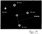
- the left image shows a cross section through a calculated volume of the same test object 3 at the same height h.
- the corresponding radii, starting from the axis of rotation 5 are indicated. This makes it clear that the results of the extended approach are consistent with the digital volume.
- the circular danger zone 7 from the first approach could be significantly reduced.
- FIG. 7 A volume rendering as a visual feedback to the user is also based on FIG. 7 possible in the form of a simplified volume reconstruction. This is shown schematically in the FIGS. 8 and 9 shown. Starting from the radii per rotation angle ⁇ and height h, any number of rotation angles ⁇ can be used for the more exact reconstruction (in FIGS. 8 and 9 the rotation angles ⁇ are considered at a distance of 30 °). To be considered then are the orthogonal, which run straight through the radius of the current rotation angle ⁇ .
- intersections of all straight lines By determining the intersections of all straight lines, a more accurate estimation of the convex hull of the test object 3 can then be made (see FIG. 8 ), the result from the second approach being called a visual envelope.
- the estimate the object envelope becomes more accurate as the number of angles of rotation ⁇ considered increases.
- the values for the radii r for ( ⁇ , h) represent another example of the abovementioned relevant parameters in the cited table. These are finer than the relevant parameters mentioned above in the first approach, since they do not give the same radius over 360 °, but instead reflect this as a function of the angle of rotation (the first approach, however, represents a coarsened envelope).
- the third approach exploits existing CT field campreconstructions (hereinafter abbreviated to FDK).
- the shadow images are interpreted as projection images of a cone beam shot with X-rays. In this case, all values equal to zero do not correspond to any attenuation of the X-rays. There were thus no debilitating objects on this path, in particular no part of the test object 3. All values not equal to zero correspond to a weakening of the radiation by the test object 3 in the beam path.
- FIG. 10 An example of this approach is FIG. 10 refer to.
- the figure shows the result of such a FDK reconstruction for the test object 3, which is in the FIGS. 1 to 4 was seen.
- an accurate statement about object parts within the convex hull is possible here.
- this information is only possible for constant rotation angle ⁇ , or the danger area 7 is also to rotate accordingly here.
- any camera position is also possible.
- the position of the camera 1 is determined by means of a corresponding calibration.
- the beam paths of the camera 1 are then tracked under the respective viewing angle and the impact on an object edge is checked.
- An example of this is in the Figures 11 and 12 shown in two-dimensional, with an extension to the third dimension is possible accordingly.
- the area in which the test object is located is divided into pixels. Along the line the pixels are traversed and weighted. In FIG. 11 Once weighted pixels are shown in one direction in semi-darkness. If more than one straight line passes through the same pixel, this pixel gets a higher weight, as indicated by the dark pixels in FIG. 12 you can see.
- the areas with high weights then form a convex hull of the test object 3.
- an exclusion method can also be carried out for each viewing angle.
- the volume to be reconstructed is considered at the appropriate angle for each projection image. All voxels that are outside the displayed object contour are removed from consideration because they can not belong to the test object 3.
- the first two approaches outlined above can also be extended with this generalized camera position.
Landscapes
- Engineering & Computer Science (AREA)
- Physics & Mathematics (AREA)
- General Physics & Mathematics (AREA)
- Theoretical Computer Science (AREA)
- Computer Vision & Pattern Recognition (AREA)
- Quality & Reliability (AREA)
- Geometry (AREA)
- Health & Medical Sciences (AREA)
- Life Sciences & Earth Sciences (AREA)
- Radiology & Medical Imaging (AREA)
- Pulmonology (AREA)
- Chemical & Material Sciences (AREA)
- Analytical Chemistry (AREA)
- Biochemistry (AREA)
- General Health & Medical Sciences (AREA)
- Immunology (AREA)
- Pathology (AREA)
- Nuclear Medicine, Radiotherapy & Molecular Imaging (AREA)
- Analysing Materials By The Use Of Radiation (AREA)
- Image Analysis (AREA)
Description
- Die Erfindung befasst sich mit einem Verfahren zur Bestimmung des Gefährdungsbereichs zwischen einem Prüfobjekt und einem Röntgenprüfsystem, die gegeneinander um eine im Prüfobjekt verlaufende Rotationsachse rotieren.
- Die Computertomographie (CT) stellt eine Bildgebungsmodalität dar, mit welcher basierend auf Röntgenstrahlung das Innere von Objekten zerstörungsfrei dargestellt werden kann. Insbesondere für die zerstörungsfreie Prüftechnik sind CT-Systeme mit möglichst vielen Freiheitsgraden für eine Aufnahme von Interesse. Bei beweglichen Geräteteilen, wie Röntgendetektor, Röntgenröhre sowie Objektteller, ist die Vermeidung einer Kollision aller Gegenstände innerhalb des Kompaktsystems von höchster Priorität. Neben einer fixen Beschränkung des befahrbaren Raumes als Kollisionsschutz, existieren noch weitere Vorgehensweisen. Bisher besteht unter anderem die Möglichkeit, eine visuelle Navigation durch Blickkontakt (beispielsweise durch ein integriertes Bleiglasfenster) zu überwachen, was jedoch deutlich durch den entsprechenden Blickwinkel eingeschränkt wird.
- Alternativ, oder zusätzlich, können Drucksensoren verwendet werden. Im Falle eines Kontaktes, wenn also bereits eine Kollision stattgefunden hat, wird das Verfahren des Objektes abgebrochen. Diese Art der Kollisionsvermeidung ist als Möglichkeit zu betrachten, die beim Versagen anderer Maßnahmen als letzte Instanz eingreift. Dadurch können größere Schäden am Objekt, beziehungsweise anderen Gegenständen innerhalb des Kompaktsystems vermieden werden. Kleinere Schäden sind jedoch durch die Kollision nicht auszuschließen.
- Die
EP 1 970 010 A1 offenbart ein Röntgen CT System und eine Methode zur Abschätzung des Umrisses eines Objekts. Das System umfasst eine Gantryeinheit, bei welcher eine Röntgenröhre und ein Röntgendetektor um das Objekt rotierbar sind. - Ein Artikel von Per-Erik Danielsson: "3D cone-beam tomography for nondestructive testing", PROCEEDINGS OF IAPR WORKSHOP ON MACHINE VISION APPLICATIONS UNIV. TOKYO, JAPAN, 1994, Seiten 1-8, offenbart ein Röntgensystem zur zerstörungsfreien Prüfung, in welchem sich das Prüfobjekt auf einem Drehtisch zwischen einer nicht rotierenden Quelle-Detektor-Anordnung befindet. Der Artikel erwähnt, dass der Quelle-Detektor Abstand größer als der maximale Objektdurchmesser sein sollte, um Kollisionen zu vermeiden.
- Die Offenlegungsschrift
JP 2012-184936 A - Der vorliegenden Erfindung liegt deshalb die Aufgabe zugrunde, eine vollautomatische und präzise Volumenerkennung bzw. Oberflächenerkennung beliebiger Prüfobjekte durchzuführen, die in weiteren Schritten der Objektpositionierung zur Vermeidung von Kollisionen verwendet werden kann.
- Gelöst wird diese Aufgabe durch ein Verfahren mit den Merkmalen des Patentanspruchs 1. Durch die erfindungsgemäßen Verfahren kann eine Objekterkennung von beliebigen Prüfobjekten durchgeführt werden. Auf deren Basis wird eine Aussage über die genaue Größe des Prüfobjekts getroffen. Die Daten hierfür werden in der Tabelle mit den relevanten Parametern abgelegt. Zu den relevanten Parametern zählt die Beziehung des jeweiligen Radius des Prüfobjekts an einem bestimmten Rotationswinkel. Diese Informationen können in weiteren Schritten zur Vermeidung von Kollisionen mit anderen Gegenständen genutzt werden, wenn beispielsweise die Position des Prüfobjektes verändert wird.
- Eine vorteilhafte Weiterbildung der Erfindung sieht vor, dass die Bestimmung der Gefährdungsradien für vorgegebene Höhen entlang der Rotationsachse separat erfolgt und die Tabelle mit den relevanten Parametern die Höhenabhängigkeit wiedergibt. Zusätzlich zu der im vorangehenden Absatz ausgeführten Beziehung zwischen Radius des Prüfobjekts und dem jeweils zugeordneten Rotationswinkel kommt hier zu den relevanten Parametern noch die Höhe, in der die vorgenannte Beziehung herrscht. Damit kann der Gefährdungsbereich für verschiedene Höhen unterschiedlich bestimmt werden.
- Eine weitere vorteilhafte Weiterbildung der Erfindung sieht vor, dass die Schritte zwischen den Rotationswinkeln kontinuierlich oder äquidistant zwischen 1° und 60°, bevorzugt 30°, betragen. Je kleiner die Rotationswinkel werden, desto exakter ist die Bestimmung des Gefährdungsbereichs; allerdings nimmt die Datenmenge und benötigte Zeit zu, so dass ein Kompromiss gefunden werden muss.
- Eine weitere vorteilhafte Weiterbildung der Erfindung sieht vor, dass als Strahlungsquelle die Röntgenröhre und als Strahlungsdetektor der Röntgendetektor des Röntgenprüfsystems verwendet werden und die bereits im Röntgenprüfsystem enthaltene CT-Feldkamprekonstruktion (FDK-Rekonstruktion) zur Bestimmung des jeweiligen Gefährdungsradius verwendet wird. Dadurch ist kein zusätzliches Kamerasystem im optischen Bereich nötig, da das Röntgenprüfsystem sowieso vorhanden ist.
- Ein Beispiel zum besseren Verständnis der Erfindung sieht vor, dass als Strahlungsdetektor eine im sichtbaren Bereich empfindliche Kamera verwendet wird und die Strahlungsquelle ein gleichmäßig mit von der Kamera registrierbarem Licht ausgeleuchteter Hintergrund ist, wobei sich das Prüfobjekt zwischen Kamera und Hintergrund befindet und der Schatten des Prüfobjekts im Gegenlicht von der Kamera aufgenommen wird. Damit kann mit einfachen Mitteln ein hervorragendes Ergebnis erzielt werden.
- Ein weiteres Beispiel sieht vor, dass die Hauptachse des Kamerablickfeldes der Kamera senkrecht auf die Rotationsachse des Prüfobjekts steht. Dadurch vereinfacht sich die zugrunde liegende Geometrie, was zu einer einfachen Berechnung der relevanten Parameter führt.
- Eine weitere vorteilhafte Weiterbildung der Erfindung sieht vor, dass die Tabelle mit den relevanten Parametern optisch dargestellt wird und/oder sie der Steuerung der Rotationsbewegung des Röntgenprüfsystems mitgeteilt wird, die daraufhin diesen Bereich bei der Röntgenprüfung des Prüfobjekts nicht anfährt. Bei der optischen Darstellung bekommt der Nutzer eine visuelle Vorstellung des Prüfobjekts und kann das Röntgenprüfsystem sicherer in die Prüfpositionen bewegen. Für den zweiten Fall wird eine vollautomatische Steuerung der Röntgenprüfung des Prüfobjekts durch das Röntgenprüfsystem vorgenommen, wobei sichergestellt ist, dass keine Kollision des Röntgenprüfsystems mit dem Prüfobjekt erfolgt.
- Weitere Vorteile und Einzelheiten der Erfindung werden anhand der in den Figuren dargestellten Ausführungsbeispiele erläutert. Es zeigen:
- Figur 1
- ein Schattenbild eines Prüfobjekts,
- Figur 2
- den Hintergrund der
Figur 1 ohne Prüfobjekt, - Figur 3
- das Differenzbild der
Figuren 1 und2 , - Figur 4
- die Binarisierung der
Figur 3 , - Figur 5
- einen schematischen Aufbau zur Durchführung eines erfindungsgemäßen Verfahrens,
- Figur 6
- eine Skizze zur Veranschaulichung der für die Berechnung relevanten geometrischen Beziehungen,
- Figur 7
- ein Ergebnis nach Durchführung einer verfeinerten erfindungsgemäßen Ausführungsform,
- Figur 8
- eine Skizze zur Veranschaulichung der Gegebenheiten bei einer verfeinerten erfindungsgemäßen Ausführungsform,
- Figur 9
- eine Skizze zur Veranschaulichung der relevanten geometrischen Beziehungen bei einem verfeinerten erfindungsgemäßen Verfahren,
- Figur 10
- eine Darstellung bei einer FDK-Rekonstruktion,
- Figur 11
- eine Darstellung von gewichteten Pixeln bei nur einem Randstrahl und
- Figur 12
- eine Darstellung von gewichteten Pixeln bei mehreren Randstrahlen.
- Im Folgenden wird ein Verfahren beschrieben, das auf Kamerabildern des Prüfobjektes basiert. Um die Ausmaße eines Prüfobjektes 3 zu bestimmen, werden Kamerabilder von verschiedenen Blickwinkeln verwendet. Es ergeben sich dafür verschiedene Möglichkeiten. Zum einen kann die Drehung des Prüfobjektes 3 um eine fixierte Rotationsachse 5 durchgeführt werden. Zum anderen kann die Kamera 1 um das Prüfobjekt 3 herum rotiert werden. Im Folgenden wird von der ersten Variante ausgegangen. Da nur die Objektkonturen von Interesse sind, werden mit Hilfe von Gegenlicht Schattenbilder aufgenommen. Dazu bildet der Hintergrund 2 die einzige, möglichst homogene Lichtquelle. Das Prüfobjekt 3 wird, bezüglich der Kamera 1, von hinten beleuchtet, wodurch sich die Objektkonturen als Schattenbegrenzung vom Hintergrund 2 abheben. Ein Beispiel eines Schattenbildes ist in
Figur 1 dargestellt. Anhand einer zusätzlichen Hintergrundaufnahme (Figur 2 ) ohne Prüfobjekt 3 und Teller kann eine Differenz gebildet werden (Figur 3 ), aus der das Prüfobjekt 3 in weiteren Schritten einfacher zu extrahieren ist.Figur 4 zeigt eine Binarisierung des Differenzbildes derFigur 3 . - Ein schematischer Testaufbau ist in
Figur 5 dargestellt. Auf der linken Seite befindet sich der homogen beleuchtete Hintergrund 2. Die Kamera 1 ist auf der rechten Seite positioniert mit Blickrichtung zum beleuchteten Hintergrund 2. Das Prüfobjekt 3 wird in den Bereich dazwischen positioniert, wodurch es sich als Schatten vom Hintergrund 2 abhebt. Um ein Schattenbild mit der Kamera 1 aufnehmen zu können, muss der Hintergrund 2 des Prüfobjektes 3 als einzige Lichtquelle existieren. - Für die folgenden Ansätze wird zunächst von einer besonderen Ausrichtung von der Kamera 1 zur Rotationsachse 5 ausgegangen. Die Hauptachse 4 des Kamerablickfeldes trifft in einem rechten Winkel auf die Rotationsachse 5. Dadurch vereinfachen sich die vorliegenden Geometrieeigenschaften, jedoch wird die vertikale Position der Kamera 1 durch diese Bedingung eingeschränkt. Es ist ebenfalls möglich, eine Volumenerkennung mit nahezu beliebiger Kameraposition durchzuführen. Darauf wird unten mit Bezug auf die
Figuren 11 und12 näher eingegangen. - Gesucht ist nun ein Algorithmus zur Volumenerkennung mit folgenden Ein- und Ausgaben:
- Eingabe: Schattenbilder mit unterschiedlichen Blickwinkeln auf das Prüfobjekt 3.
- Ausgabe: Verschiedene Komplexitätsstufen sind denkbar:
- 1. Höhe h mit entsprechend maximalem Objektradius rmax in Relation zur Rotationsachse 5,
- 2. Höhe h, Rotationswinkel γ mit entsprechendem Objektradius r in Relation zur Rotationsachse 5,
- 3. dreidimensionales Volumen, das zur Darstellung für den Benutzer verwendet werden kann.
- Mit dem Objektradius rmax ist der Radius gemeint, den das Prüfobjekt 3 ausgehend von der Rotationsachse 5 bei einer Rotation maximal einnimmt. Dieser Parameter ist je nach Höhe h variabel. Weiterhin ist die Angabe des Rotationswinkels γ als Variable denkbar, für die zusammen mit der Höhe h ein entsprechender Objektradius r existiert. Im Idealfall sollte nach der Volumenerkennung außerdem eine dreidimensionale Objektdarstellung am PC des Benutzers verfügbar sein, um einen visuellen Eindruck der Volumenerkennung zu gewährleisten.
- Für alle Komplexitätsstufen erfolgt zunächst eine Binarisierung des Prüfobjektes 3, wie sie exemplarisch in
Figur 4 dargestellt ist. An allen Objektpositionen befindet sich in diesen Bildern ein Wert ungleich Null. - Sofern ausreichend Informationen über die Geometrie vorliegen, ist eine Aussage über den maximalen Radius rmax bezüglich der Höhe h mit wenig Rechenaufwand anhand einer direkten Auswertung der Binärbilder möglich.
Figur 5 zeigt eine schematische Darstellung eines entsprechenden Versuchsaufbaus mit einem Betrachtungswinkel von oben. Ziel ist es zunächst, den dunklen Kreis zu finden, der durch rmax definiert wird und den Gefährdungsbereich 7 für einen Kollisionsschutz darstellt. Der Gefährdungsbereich 7 korreliert mit dem Gefährdungsradius 8, der bei den erfindungsgemäßen Verfahren bestimmt wird. Dieser Kreis beinhaltet das gesamte Prüfobjekt 3 für alle Rotationsbewegungen um die Rotationsachse 5. Externe Gegenstände dürften sich nicht innerhalb dieses Bereiches befinden, da sich für mindestens eine (nicht notwendigerweise alle) Winkelpositionen eine Kollision mit dem Prüfobjekt 3 ergeben würde. Der Parameter FOD repräsentiert den Abstand zwischen Kamera 1 und der Rotationsachse 5. Der Abstand DOD gibt die Distanz zwischen Prüfobjekt und einer theoretischen Bildebene hinter dem Prüfobjekt 3 an. Der Parameter s repräsentiert die Größe des Objektschattens auf dem Kamerabild. Das temporäre Maß r' kann verwendet werden, um die eigentlich gesuchte Größe rmax zu bestimmen. - Durch die bekannte Geometrie kann davon ausgegangen werden, dass der Abstand zwischen Prüfobjekt 3 und Kamera 1, in
Figur 6 mit FOD bezeichnet, bekannt ist. Dafür kann das Prüfobjekt 3 im Vorfeld an eine vordefinierte Position innerhalb des Kamerablickfeldes positioniert worden sein. Da die Bildebene auf der anderen Seite des Prüfobjektes 3 theoretisch angenommen wird, kann die Entfernung DOD zwischen Prüfobjekt 3 und dieser Ebene beliebig gewählt werden. Der Einfachheit halber wird FOD = DOD gewählt. - Zur Bestimmung der Schattengröße s ist zwar bereits die Anzahl von Pixeln innerhalb des Binärbildes gegeben, jedoch ist noch die Pixelgröße für die theoretische Bildebene zu bestimmen. Nach dem Strahlensatz folgt

- Es ist weiterhin möglich, die Strecke r' mit dem Strahlensatz zu bestimmen

- Der gesuchte Radius rmax ergibt sich dann aus der Höhenbestimmung des rechtwinkligen Dreiecks, das durch FOD und r' aufgespannt wird

- Die einzelnen Schritte des ersten Ansatzes lauten somit zusammengefasst:
- 1. Alle Binärbilder zeilenweise durchlaufen und die Objektkanten ermitteln.
- 2. Für jede Höhe den größten Abstand rmax des Objektrandes zur Rotationsachse 5 bestimmen.
- 3. Ausgabe der Wertepaare h und rmax.
- 4. Dem Benutzer kann ein Zylinder in Form der jeweiligen Radien rmax als visuelle Rückmeldung angezeigt werden.
- Die genannten Wertepaare h und rmax sind ein Beispiel für die oben genannten relevanten Parameter in der genannten Tabelle.
- Es ist denkbar, nicht nur eine Kante zu betrachten. Beispielsweise kann nur die Hälfte aller Projektionen verwendet werden, wenn die rechte und linke Kante entsprechend betrachtet werden. Es ist ebenfalls möglich, beide Kanten zu betrachten und das entsprechende Maximum zu verwenden, um mögliche Fehlerquellen, wie beispielsweise Beleuchtung, Reflexion und Rauschen zu minimieren.
- Als zweiter Ansatz ist es möglich, die zuvor vorgestellte direkte Auswertung der Binärbilder für jede Höhe nicht auf den maximalen Radius rmax zu beschränken. Wird für jedes Projektionsbild unter variierendem Rotationswinkel γ die Objektkante bestimmt, kann der zuvor kreisförmige Gefährdungsbereich 7 reduziert werden.
- Für diesen Ansatz wird der Rotationswinkel γ zwischen r' und dem jeweiligen r von Interesse. Dieser Offset des Rotationswinkels γ für den bestimmten Radius wird als ω bezeichnet und lässt sich durch

- Ein Beispiel für diesen erweiterten Ansatz, welcher einen Radius r für jedes Rotationswinkel-Höhe-Paar (γ, h) liefert, ist in
Figur 7 zu sehen. Zur Orientierung zeigt das linke Bild einen Querschnitt durch ein berechnetes Volumen des gleichen Prüfobjektes 3 in der gleichen Höhe h. Außerdem werden die entsprechenden Radien, ausgehend von der Rotationsachse 5 angegeben. Dadurch wird deutlich, dass die Ergebnisse des erweiterten Ansatzes mit dem digitalen Volumen übereinstimmen. Der kreisförmige Gefährdungsbereich 7 aus dem ersten Ansatz konnte deutlich reduziert werden. - Das Ergebnis dieses Ansatzes ist somit eine genauere Angabe des Gefährdungsbereiches 7, wobei ein Kollisionsschutz jedoch nicht mehr für beliebige Rotationswinkel γ gewährleistet ist. Der Gefährdungsbereich 7, wie er in
Figur 7 dargestellt ist, gilt entweder nur für die initiale Winkelposition oder muss entsprechend mit rotiert werden. - Eine Volumendarstellung als visuelle Rückmeldung für den Benutzer ist außerdem auf Basis von
Figur 7 in Form einer vereinfachten Volumenrekonstruktion möglich. Diese wird schematisch in denFiguren 8 und9 dargestellt. Ausgehend von den Radien pro Rotationswinkel γ und Höhe h können beliebig viele Rotationswinkel γ für die exaktere Rekonstruktion verwendet werden (inFiguren 8 und9 werden die Rotationswinkel γ mit einem Abstand von 30° betrachtet). Zu betrachten sind dann die Orthogonalen, die gerade durch den Radius des momentanen Rotationswinkels γ verlaufen. - Durch die Ermittlung der Schnittpunkte aller Geraden kann dann eine genauere Abschätzung der konvexen Hülle des Prüfobjektes 3 gemacht werden (siehe
Figur 8 ), wobei das Ergebnis vom zweiten Ansatz als visuelle Hülle bezeichnet werden kann. Die Schnittpunkte können anhand der Informationen, die inFigur 9 als Beispiel für den Rotationswinkel γ = 30° angegeben sind, bestimmt werden. Die Abschätzung der Objekthülle wird mit zunehmender Anzahl an betrachteten Rotationswinkeln γ genauer. - Zusammenfassend ergeben sich für diesen zweiten Ansatz die folgenden Schritte:
- 1. Alle Binärbilder zeilenweise durchlaufen und die Objektkanten ermitteln.
- 2. Für jeden Rotationswinkel γ und jede Höhe h den Radius r bestimmen.
- 3. Ausgabe von r pro Paar (γ, h).
- 4. Dem Benutzer können die Radien r für (γ, h) als dreidimensionales Volumen dargestellt werden (siehe
Figur 7 für eine exemplarische horizontale Schicht). - Die Werte für die Radien r für (γ, h) stellen ein anderes Beispiel für die oben genannten relevanten Parameter in der genannten Tabelle. Diese sind feiner als die oben bei dem ersten Ansatz genannten relevanten Parameter, da sie nicht über 360° denselben Radius angeben, sondern diesen in Abhängigkeit vom Rotationswinkel wiedergeben (der erste Ansatz hingegen gibt eine vergröberte Umhüllende wieder).
- Der dritte Ansatz nutzt bereits existierende CT-Feldkamprekonstruktionen aus (im Folgenden durch FDK abgekürzt). Die Schattenbilder werden dafür als Projektionsbilder einer Kegelstrahlaufnahme mit Röntgenstrahlung interpretiert. Dabei entsprechen dann alle Werte gleich Null keiner Abschwächung der Röntgenstrahlen. Es befanden sich auf diesem Weg somit keinerlei schwächende Objekte, insbesondere kein Teil des Prüfobjektes 3. Aller Werte ungleich Null entsprechen einer Abschwächung der Strahlung durch das Prüfobjekt 3 im Strahlengang.
- Die einzelnen Schritte des dritten Ansatzes lauten zusammengefasst:
- 1. Einen gegebenen FDK-Algorithmus anwenden, der ein dreidimensionales Volumen liefert.
- 2. Eine Segmentierung der Objektbereiche vom Hintergrund wird durchgeführt, was ein binäres Volumen liefert.
- 3. Aus dem binären Volumen kann entweder rmax pro h oder r für jedes Paar (γ, h) bestimmt werden.
- 4. Das unsegmentierte Ergebnisvolumen kann dem Benutzer als visuelle Rückmeldung dargestellt werden, in der er für weitere Schritte genaueste Navigationsbefehle durchführen kann.
- Ein Beispiel für diesen Ansatz ist
Figur 10 zu entnehmen. Die Abbildung zeigt das Ergebnis solch einer FDK-Rekonstruktion für das Prüfobjekt 3, das in denFiguren 1 bis 4 zu sehen war. Im Gegensatz zu den vorherigen Verfahren ist hier eine genaue Aussage über Objektteile innerhalb der konvexen Hülle möglich. Hier ist jedoch zu beachten, dass diese Information ausschließlich für gleichbleibenden Rotationswinkel γ möglich ist, beziehungsweise der Gefährdungsbereich 7 auch hier entsprechend zu rotieren ist. - Alternativ zu den zuvor vorgestellten Verfahren, ist die Verwendung einer beliebigen Kameraposition ebenfalls möglich. Die Position der Kamera 1 wird anhand einer entsprechenden Kalibrierung ermittelt. Es werden dann für eine Volumenerkennung die Strahlenverläufe der Kamera 1 unter dem jeweiligen Blickwinkel nachverfolgt und das Auftreffen auf eine Objektkante geprüft. Ein Beispiel dazu ist in den
Figuren 11 und12 im Zweidimensionalen dargestellt, wobei eine Erweiterung auf die dritte Dimension entsprechend möglich ist. Der Bereich, in dem sich das Prüfobjekt befindet, wird in Pixel unterteilt. Entlang der Geraden werden die Pixel traversiert und gewichtet. InFigur 11 sind einmal gewichtete Pixel aus einer Blickrichtung in halbdunkel dargestellt. Falls mehrere Geraden durch dasselbe Pixel verlaufen, erhält dieses Pixel ein höheres Gewicht, wie anhand der dunklen Pixel inFigur 12 zu sehen ist. Die Bereiche mit hohen Gewichten bilden dann eine konvexe Hülle des Prüfobjektes 3. - Anstatt der beschriebenen Höhergewichtung, bei der Hintergrundartefakte im Volumen entstehen, kann auch ein Ausschlussverfahren für jeden Blickwinkel durchgeführt werden. Das zu rekonstruierende Volumen wird für jedes Projektionsbild unter dem entsprechenden Winkel betrachtet. Alle Voxel, die sich außerhalb der dargestellten Objektkontur befinden, werden aus der Betrachtung entfernt, da sie nicht zum Prüfobjekt 3 gehören können. Die oben ausgeführten ersten beiden Ansätze können mit dieser verallgemeinerten Kameraposition ebenfalls erweitert werden.
- Zusammenfassend, bieten alle Ansätze die Möglichkeit, eine adäquate Volumenerkennung und einen darauf basierenden Kollisionsschutz umzusetzen. Die Verfahren erfordern jedoch mit zunehmender Genauigkeit und Flexibilität ebenfalls einen zunehmenden Rechenaufwand. Denkbar ist daher ein gestaffelter Ansatz, der mit einer einfachen, zylindrischen Volumenerkennung beginnt und dann, je nach Wunsch des Benutzers, weitere Schritte für eine präzisere Aussage und Volumendarstellung vornimmt.
- Bezogen auf den speziellen Bereich der Computertomographie ergibt sich außerdem noch eine weitere Möglichkeit, die Präzision zu erhöhen. Alle vorgestellten Verfahren sind in ihrer Auflösungsfähigkeit auf die Qualität der verwendeten Kamera beschränkt. Alternativ kann für einen genügend kleinen Bereich ebenfalls das eigentliche Röntgenbild mit den gleichen Verfahren für eine Volumenerkennung verwendet werden. In der Regel weisen Röntgendetektoren wesentlich höhere Auflösungen auf, als standardmäßig verwendete Kameras 1.
-
- 1
- Kamera
- 2
- beleuchteter Hintergrund
- 3
- Prüfobjekt
- 4
- Hauptachse
- 5
- Rotationsachse
- 6
- Randstrahl
- 7
- Gefährdungsbereich
- 8
- Gefährdungsradius
- h
- Höhe
- γ
- Rotationswinkel
Claims (6)
- Verfahren zur Steuerung einer Röntgenprüfung eines Prüfobjekts durch ein Röntgenprüfsystem, wobei das Röntgenprüfsystem umfasst:- eine Strahlungsquelle,- einen zu der Strahlungsquelle in einem vorgegebenen Abstand angeordneten Strahlungsdetektor,- eine Steuereinrichtung zur Steuerung einer Rotationsbewegung des Röntgenprüfsystems,das Verfahren umfassend:- Durchführen einer Bestimmung des Gefährdungsbereichs (7) für einen Kollisionsschutz zwischen dem Prüfobjekt (3) und dem Röntgenprüfsystem, die gegeneinander um eine im Prüfobjekt (3) verlaufende Rotationsachse (5) rotieren, wobei mittels der Strahlungsquelle und dem Strahlungsdetektor diejenigen Randstrahlen (6) bestimmt werden, die unter einem vorgegebenen Rotationswinkel (γ) zwischen Prüfobjekt (3) und Strahlungsquelle-Strahlungsdetektor-Anordnung die Außenkontur des Prüfobjekts (3) unter diesem Rotationswinkel (γ) streifen, die Bestimmung des Gefährdungsbereichs (7) umfassend:Bestimmung des Gefährdungsradius (8) der Außenkontur zur Rotationsachse (5) des Prüfobjekts (3) für den vorgegebenen Rotationswinkel (γ),Wiederholung der Bestimmung der Randstrahlen (6) für vorgegebene Rotationswinkel (γ), die über 360° verteilt sind und Bestimmung des jeweiligen Gefährdungsradius (8), Erstellung einer Tabelle mit den relevanten Parametern der für die vorgegebenen Rotationswinkel (γ) erhaltenen Gefährdungsradien (8) des Randes des Prüfobjekts (3),Mitteilen der Tabelle an eine Steuerung der Rotationsbewegung des Röntgenprüfsystems;- vollautomatisiertes Steuern der Röntgenprüfung derart, dass die Steuerung diesen Bereich bei der Röntgenprüfung des Prüfobjekts (3) nicht anfährt und sicherstellt, dass beim Verändern der Position des Prüfobjekts keine Kollision des Röntgenprüfsystems mit dem Prüfobjekt erfolgt.
- Verfahren nach Patentanspruch 1, wobei die Bestimmung der Gefährdungsradien (8) für vorgegebene Höhen (h) entlang der Rotationsachse (5) separat erfolgt und die Tabelle mit den relevanten Parametern die Höhenabhängigkeit wiedergibt.
- Verfahren nach einem der vorstehenden Patentansprüche, wobei die Schritte zwischen den Rotationswinkel (γ) kontinuierlich oder äquidistant zwischen 1° und 60°, bevorzugt 30°, betragen.
- Verfahren nach einem der vorstehenden Patentansprüche, wobei die bereits im Röntgenprüfsystem enthaltene CT-Feldkamprekonstruktion zur Bestimmung des jeweiligen Gefährdungsradius (8) verwendet wird.
- Verfahren nach einem der vorstehenden Patentansprüche, wobei die Tabelle mit den relevanten Parametern optisch dargestellt wird.
- Röntgenprüfsystem zur Röntgenprüfung eines Prüfobjekts, wobei das Röntgenprüfsystem umfasst:- eine Strahlungsquelle,- einen zu der Strahlungsquelle in einem vorgegebenen Abstand angeordneten Strahlungsdetektor,- eine Steuereinrichtung zur Steuerung einer Rotationsbewegung des Röntgenprüfsystems,wobei das Röntgenprüfsystem dazu eingerichtet ist, eine Bestimmung eines Gefährdungsbereichs (7) für einen Kollisionsschutz zwischen dem Prüfobjekt (3) und dem Röntgenprüfsystem durchzuführen, die gegeneinander um eine im Prüfobjekt (3) verlaufende Rotationsachse (5) rotieren,wobei mittels der Strahlungsquelle und dem Strahlungsdetektor diejenigen Randstrahlen (6) bestimmt werden, die unter einem vorgegebenen Rotationswinkel (γ) zwischen Prüfobjekt (3) und Strahlungsquelle-Strahlungsdetektor-Anordnung die Außenkontur des Prüfobjekts (3) unter diesem Rotationswinkel (γ) streifen, die Bestimmung des Gefährdungsbereichs (7) umfassend:Bestimmung des Gefährdungsradius (8) der Außenkontur zur Rotationsachse (5) des Prüfobjekts (3) für den vorgegebenen Rotationswinkel (γ),Wiederholung der Bestimmung der Randstrahlen (6) für vorgegebene Rotationswinkel (γ), die über 360° verteilt sind und Bestimmung des jeweiligen Gefährdungsradius (8),Erstellung einer Tabelle mit den relevanten Parametern der für die vorgegebenen Rotationswinkel (γ) erhaltenen Gefährdungsradien (8) des Randes des Prüfobjekts (3),Mitteilen der Tabelle an die Steuereinrichtung zur Steuerung der Rotationsbewegung des Röntgenprüfsystems;und wobei das Röntegenprüfsystem ferner dazu eingerichtet ist, die vollautomatisierte Steuerung der Röntgenprüfung derart vorzunehmen, dass die Steuerung diesen Bereich bei der Röntgenprüfung des Prüfobjekts (3) nicht anfährt und sicherstellt, dass beim Verändern der Position des Prüfobjekts keine Kollision des Röntgenprüfsystems mit dem Prüfobjekt erfolgt.
Applications Claiming Priority (2)
| Application Number | Priority Date | Filing Date | Title |
|---|---|---|---|
| DE102013017459 | 2013-10-21 | ||
| PCT/EP2014/002840 WO2015058854A1 (de) | 2013-10-21 | 2014-10-21 | Verfahren zur bestimmung des gefährdungsbereichs zwischen einem prüfobjekt und einem röntgenprüfsystem |
Publications (2)
| Publication Number | Publication Date |
|---|---|
| EP3061068A1 EP3061068A1 (de) | 2016-08-31 |
| EP3061068B1 true EP3061068B1 (de) | 2019-04-24 |
Family
ID=51845368
Family Applications (1)
| Application Number | Title | Priority Date | Filing Date |
|---|---|---|---|
| EP14792739.6A Active EP3061068B1 (de) | 2013-10-21 | 2014-10-21 | Verfahren zur bestimmung des gefährdungsbereichs zwischen einem prüfobjekt und einem röntgenprüfsystem |
Country Status (8)
| Country | Link |
|---|---|
| US (1) | US20160253827A1 (de) |
| EP (1) | EP3061068B1 (de) |
| JP (1) | JP6500016B2 (de) |
| KR (1) | KR102217860B1 (de) |
| CN (1) | CN105659290A (de) |
| DE (1) | DE112014004803A5 (de) |
| GB (1) | GB2534091A (de) |
| WO (1) | WO2015058854A1 (de) |
Families Citing this family (2)
| Publication number | Priority date | Publication date | Assignee | Title |
|---|---|---|---|---|
| US11009449B2 (en) * | 2018-04-20 | 2021-05-18 | Fei Company | Scanning trajectories for region-of-interest tomograph |
| CN118913163B (zh) * | 2024-10-10 | 2025-03-07 | 宁德时代新能源科技股份有限公司 | 圆度检测方法、装置、系统、电子设备、介质及产品 |
Citations (1)
| Publication number | Priority date | Publication date | Assignee | Title |
|---|---|---|---|---|
| JP2012184936A (ja) * | 2011-03-03 | 2012-09-27 | Shimadzu Corp | X線検査装置 |
Family Cites Families (8)
| Publication number | Priority date | Publication date | Assignee | Title |
|---|---|---|---|---|
| US1970010A (en) * | 1932-09-03 | 1934-08-14 | Charles H Long | Fuel vaporizer and carburetor |
| JP4704735B2 (ja) * | 2004-11-04 | 2011-06-22 | 株式会社島津製作所 | X線透視装置 |
| US7792242B2 (en) * | 2004-11-12 | 2010-09-07 | Shimadzu Corporation | X-ray CT system and X-ray CT method |
| JP4715409B2 (ja) * | 2005-09-15 | 2011-07-06 | 株式会社島津製作所 | X線検査装置 |
| JP2008220653A (ja) * | 2007-03-13 | 2008-09-25 | Toshiba Corp | X線ct装置、被検体外形推定方法、画像再構成方法 |
| DE102007016370A1 (de) * | 2007-04-03 | 2008-10-09 | Carl Zeiss Industrielle Messtechnik Gmbh | Verfahren und eine Messanordnung zum Erzeugen von dreidimensionalen Bildern von Messobjekten mittels invasiver Strahlung |
| JP2009294047A (ja) * | 2008-06-04 | 2009-12-17 | Shimadzu Corp | X線検査装置 |
| EP3266381B1 (de) * | 2010-12-22 | 2022-01-05 | ViewRay Technologies, Inc. | System und verfahren zur bildführung während medizinischer eingriffe |
-
2014
- 2014-10-21 WO PCT/EP2014/002840 patent/WO2015058854A1/de not_active Ceased
- 2014-10-21 JP JP2016518766A patent/JP6500016B2/ja active Active
- 2014-10-21 US US15/030,598 patent/US20160253827A1/en not_active Abandoned
- 2014-10-21 GB GB1606369.5A patent/GB2534091A/en not_active Withdrawn
- 2014-10-21 CN CN201480057708.9A patent/CN105659290A/zh active Pending
- 2014-10-21 DE DE112014004803.8T patent/DE112014004803A5/de not_active Withdrawn
- 2014-10-21 KR KR1020167013349A patent/KR102217860B1/ko active Active
- 2014-10-21 EP EP14792739.6A patent/EP3061068B1/de active Active
Patent Citations (1)
| Publication number | Priority date | Publication date | Assignee | Title |
|---|---|---|---|---|
| JP2012184936A (ja) * | 2011-03-03 | 2012-09-27 | Shimadzu Corp | X線検査装置 |
Also Published As
| Publication number | Publication date |
|---|---|
| GB2534091A (en) | 2016-07-13 |
| KR20160101903A (ko) | 2016-08-26 |
| DE112014004803A5 (de) | 2016-08-25 |
| EP3061068A1 (de) | 2016-08-31 |
| JP2016537620A (ja) | 2016-12-01 |
| US20160253827A1 (en) | 2016-09-01 |
| KR102217860B1 (ko) | 2021-02-22 |
| CN105659290A (zh) | 2016-06-08 |
| WO2015058854A1 (de) | 2015-04-30 |
| JP6500016B2 (ja) | 2019-04-10 |
Similar Documents
| Publication | Publication Date | Title |
|---|---|---|
| EP2399237B1 (de) | Verfahren zum messen eines objekts | |
| DE102007056980B4 (de) | Verfahren und Vorrichtung für die Computertomographie | |
| EP3688725B1 (de) | Verfahren und vorrichtung zum erzeugen einer 3d-rekonstruktion eines objekts | |
| EP3304025B1 (de) | Verfahren und vorrichtung zum bestimmen von oberflächendaten und/oder messdaten einer oberfläche eines zumindest teilweise transparenten objekts | |
| EP2494522B1 (de) | Verfahren zur bestimmung eines satzes von optischen abbildungsfunktionen für die 3d-strömungsmessung | |
| DE102013108367A1 (de) | Vorrichtung und Verfahren zur Aufnahme von Durchstrahlungsbildern bei einer Computertomografie | |
| DE102016101005A1 (de) | Vorrichtung und Verfahren zur computertomografischen Messung eines Werkstücks | |
| DE102010040963A1 (de) | Verfahren und Röntgengerät zur Erzeugung eines Röntgen-Projektionsbildes | |
| EP3586308B1 (de) | Verfahren und vorrichtung zur mehrfachkantenerkennung | |
| EP3420533B1 (de) | Verfahren zum kalibrieren eines optischen messaufbaus | |
| WO2007131724A1 (de) | Vorrichtung zur dreidimensionalen vermessung eines festkörpers | |
| WO2007131723A1 (de) | Verfahren zum vermessen eines festkörpers | |
| EP3992620B1 (de) | Computerimplementiertes verfahren zur ermittlung mindestens eines für eine auswertung von messdaten benötigten geometrischen parameters | |
| WO2015058854A1 (de) | Verfahren zur bestimmung des gefährdungsbereichs zwischen einem prüfobjekt und einem röntgenprüfsystem | |
| DE102014116595A1 (de) | Vorrichtung und Verfahren zum Einsatz mehrerer Detektoren bei der dimensionellen Messung mit einer Computertomografiesensorik | |
| DE102014113977A1 (de) | Verfahren zur Bestimmung zumindest eines Parameters bei der dimensionellen Messung mit einer Computertomografiesensorik | |
| WO2023161083A1 (de) | Computerimplementiertes verfahren, computerprogramm, datenverarbeitungssystem und vorrichtung zur bestimmung des reflektanzverhaltens einer oberfläche eines objektes sowie speichermedium mit darauf gespeicherten instruktionen zur bestimmung des reflektanzverhaltens einer oberfläche eines objektes | |
| WO2012152738A1 (de) | BESTIMMUNG VON MAßEN EINES WERKSTÜCKS | |
| DE102010022285A1 (de) | Verfahren zur Bestimmung der optimalen Lage eines Messobjektes bei der 3D-Computertomografie | |
| DE102022103888A1 (de) | Verfahren und Vorrichtung zur Computertomografiemessung | |
| EP3586307B1 (de) | Verfahren und vorrichtung zur erkennung von ecken | |
| DE102015209284A1 (de) | Verfahren zum Erzeugen einer Ansicht einer Fahrzeugumgebung | |
| DE102010037305A1 (de) | Tomografisches Verfahren zur Erfassung des dreidimensionalen Verlaufs und von dreidimensionalen Verformungen von Oberflächen | |
| DE102021103086A1 (de) | Verfahren zum Betreiben eines Koordinatenmessgeräts | |
| DE102017000454A1 (de) | Verfahren, System und Fahrzeug zum Kalibrieren von Bilddaten zweier Kameras |
Legal Events
| Date | Code | Title | Description |
|---|---|---|---|
| PUAI | Public reference made under article 153(3) epc to a published international application that has entered the european phase |
Free format text: ORIGINAL CODE: 0009012 |
|
| 17P | Request for examination filed |
Effective date: 20160523 |
|
| AK | Designated contracting states |
Kind code of ref document: A1 Designated state(s): AL AT BE BG CH CY CZ DE DK EE ES FI FR GB GR HR HU IE IS IT LI LT LU LV MC MK MT NL NO PL PT RO RS SE SI SK SM TR |
|
| AX | Request for extension of the european patent |
Extension state: BA ME |
|
| DAX | Request for extension of the european patent (deleted) | ||
| STAA | Information on the status of an ep patent application or granted ep patent |
Free format text: STATUS: EXAMINATION IS IN PROGRESS |
|
| 17Q | First examination report despatched |
Effective date: 20170303 |
|
| RIC1 | Information provided on ipc code assigned before grant |
Ipc: G06T 11/00 20060101AFI20181018BHEP Ipc: G01N 23/046 20160831ALI20181018BHEP Ipc: G06T 7/62 20160831ALI20181018BHEP Ipc: G06T 7/00 20060101ALI20181018BHEP |
|
| RIC1 | Information provided on ipc code assigned before grant |
Ipc: G06T 11/00 20060101AFI20181018BHEP Ipc: G06T 7/62 20170101ALI20181018BHEP Ipc: G01N 23/046 20180101ALI20181018BHEP Ipc: G06T 7/00 20170101ALI20181018BHEP |
|
| GRAP | Despatch of communication of intention to grant a patent |
Free format text: ORIGINAL CODE: EPIDOSNIGR1 |
|
| STAA | Information on the status of an ep patent application or granted ep patent |
Free format text: STATUS: GRANT OF PATENT IS INTENDED |
|
| RIC1 | Information provided on ipc code assigned before grant |
Ipc: G06T 7/00 20170101ALI20181018BHEP Ipc: G01N 23/046 20180101ALI20181018BHEP Ipc: G06T 7/62 20170101ALI20181018BHEP Ipc: G06T 11/00 20060101AFI20181018BHEP |
|
| INTG | Intention to grant announced |
Effective date: 20190121 |
|
| GRAS | Grant fee paid |
Free format text: ORIGINAL CODE: EPIDOSNIGR3 |
|
| GRAA | (expected) grant |
Free format text: ORIGINAL CODE: 0009210 |
|
| STAA | Information on the status of an ep patent application or granted ep patent |
Free format text: STATUS: THE PATENT HAS BEEN GRANTED |
|
| AK | Designated contracting states |
Kind code of ref document: B1 Designated state(s): AL AT BE BG CH CY CZ DE DK EE ES FI FR GB GR HR HU IE IS IT LI LT LU LV MC MK MT NL NO PL PT RO RS SE SI SK SM TR |
|
| REG | Reference to a national code |
Ref country code: GB Ref legal event code: FG4D Free format text: NOT ENGLISH |
|
| REG | Reference to a national code |
Ref country code: CH Ref legal event code: EP |
|
| REG | Reference to a national code |
Ref country code: DE Ref legal event code: R096 Ref document number: 502014011532 Country of ref document: DE |
|
| REG | Reference to a national code |
Ref country code: AT Ref legal event code: REF Ref document number: 1125024 Country of ref document: AT Kind code of ref document: T Effective date: 20190515 Ref country code: IE Ref legal event code: FG4D Free format text: LANGUAGE OF EP DOCUMENT: GERMAN |
|
| REG | Reference to a national code |
Ref country code: NL Ref legal event code: MP Effective date: 20190424 |
|
| REG | Reference to a national code |
Ref country code: LT Ref legal event code: MG4D |
|
| PG25 | Lapsed in a contracting state [announced via postgrant information from national office to epo] |
Ref country code: NL Free format text: LAPSE BECAUSE OF FAILURE TO SUBMIT A TRANSLATION OF THE DESCRIPTION OR TO PAY THE FEE WITHIN THE PRESCRIBED TIME-LIMIT Effective date: 20190424 |
|
| PG25 | Lapsed in a contracting state [announced via postgrant information from national office to epo] |
Ref country code: PT Free format text: LAPSE BECAUSE OF FAILURE TO SUBMIT A TRANSLATION OF THE DESCRIPTION OR TO PAY THE FEE WITHIN THE PRESCRIBED TIME-LIMIT Effective date: 20190824 Ref country code: ES Free format text: LAPSE BECAUSE OF FAILURE TO SUBMIT A TRANSLATION OF THE DESCRIPTION OR TO PAY THE FEE WITHIN THE PRESCRIBED TIME-LIMIT Effective date: 20190424 Ref country code: AL Free format text: LAPSE BECAUSE OF FAILURE TO SUBMIT A TRANSLATION OF THE DESCRIPTION OR TO PAY THE FEE WITHIN THE PRESCRIBED TIME-LIMIT Effective date: 20190424 Ref country code: HR Free format text: LAPSE BECAUSE OF FAILURE TO SUBMIT A TRANSLATION OF THE DESCRIPTION OR TO PAY THE FEE WITHIN THE PRESCRIBED TIME-LIMIT Effective date: 20190424 Ref country code: SE Free format text: LAPSE BECAUSE OF FAILURE TO SUBMIT A TRANSLATION OF THE DESCRIPTION OR TO PAY THE FEE WITHIN THE PRESCRIBED TIME-LIMIT Effective date: 20190424 Ref country code: NO Free format text: LAPSE BECAUSE OF FAILURE TO SUBMIT A TRANSLATION OF THE DESCRIPTION OR TO PAY THE FEE WITHIN THE PRESCRIBED TIME-LIMIT Effective date: 20190724 Ref country code: FI Free format text: LAPSE BECAUSE OF FAILURE TO SUBMIT A TRANSLATION OF THE DESCRIPTION OR TO PAY THE FEE WITHIN THE PRESCRIBED TIME-LIMIT Effective date: 20190424 Ref country code: LT Free format text: LAPSE BECAUSE OF FAILURE TO SUBMIT A TRANSLATION OF THE DESCRIPTION OR TO PAY THE FEE WITHIN THE PRESCRIBED TIME-LIMIT Effective date: 20190424 |
|
| PG25 | Lapsed in a contracting state [announced via postgrant information from national office to epo] |
Ref country code: RS Free format text: LAPSE BECAUSE OF FAILURE TO SUBMIT A TRANSLATION OF THE DESCRIPTION OR TO PAY THE FEE WITHIN THE PRESCRIBED TIME-LIMIT Effective date: 20190424 Ref country code: PL Free format text: LAPSE BECAUSE OF FAILURE TO SUBMIT A TRANSLATION OF THE DESCRIPTION OR TO PAY THE FEE WITHIN THE PRESCRIBED TIME-LIMIT Effective date: 20190424 Ref country code: LV Free format text: LAPSE BECAUSE OF FAILURE TO SUBMIT A TRANSLATION OF THE DESCRIPTION OR TO PAY THE FEE WITHIN THE PRESCRIBED TIME-LIMIT Effective date: 20190424 Ref country code: BG Free format text: LAPSE BECAUSE OF FAILURE TO SUBMIT A TRANSLATION OF THE DESCRIPTION OR TO PAY THE FEE WITHIN THE PRESCRIBED TIME-LIMIT Effective date: 20190724 Ref country code: GR Free format text: LAPSE BECAUSE OF FAILURE TO SUBMIT A TRANSLATION OF THE DESCRIPTION OR TO PAY THE FEE WITHIN THE PRESCRIBED TIME-LIMIT Effective date: 20190725 |
|
| PG25 | Lapsed in a contracting state [announced via postgrant information from national office to epo] |
Ref country code: IS Free format text: LAPSE BECAUSE OF FAILURE TO SUBMIT A TRANSLATION OF THE DESCRIPTION OR TO PAY THE FEE WITHIN THE PRESCRIBED TIME-LIMIT Effective date: 20190824 |
|
| REG | Reference to a national code |
Ref country code: DE Ref legal event code: R097 Ref document number: 502014011532 Country of ref document: DE |
|
| PG25 | Lapsed in a contracting state [announced via postgrant information from national office to epo] |
Ref country code: EE Free format text: LAPSE BECAUSE OF FAILURE TO SUBMIT A TRANSLATION OF THE DESCRIPTION OR TO PAY THE FEE WITHIN THE PRESCRIBED TIME-LIMIT Effective date: 20190424 Ref country code: DK Free format text: LAPSE BECAUSE OF FAILURE TO SUBMIT A TRANSLATION OF THE DESCRIPTION OR TO PAY THE FEE WITHIN THE PRESCRIBED TIME-LIMIT Effective date: 20190424 Ref country code: RO Free format text: LAPSE BECAUSE OF FAILURE TO SUBMIT A TRANSLATION OF THE DESCRIPTION OR TO PAY THE FEE WITHIN THE PRESCRIBED TIME-LIMIT Effective date: 20190424 Ref country code: SK Free format text: LAPSE BECAUSE OF FAILURE TO SUBMIT A TRANSLATION OF THE DESCRIPTION OR TO PAY THE FEE WITHIN THE PRESCRIBED TIME-LIMIT Effective date: 20190424 Ref country code: CZ Free format text: LAPSE BECAUSE OF FAILURE TO SUBMIT A TRANSLATION OF THE DESCRIPTION OR TO PAY THE FEE WITHIN THE PRESCRIBED TIME-LIMIT Effective date: 20190424 |
|
| PG25 | Lapsed in a contracting state [announced via postgrant information from national office to epo] |
Ref country code: SM Free format text: LAPSE BECAUSE OF FAILURE TO SUBMIT A TRANSLATION OF THE DESCRIPTION OR TO PAY THE FEE WITHIN THE PRESCRIBED TIME-LIMIT Effective date: 20190424 |
|
| PLBE | No opposition filed within time limit |
Free format text: ORIGINAL CODE: 0009261 |
|
| STAA | Information on the status of an ep patent application or granted ep patent |
Free format text: STATUS: NO OPPOSITION FILED WITHIN TIME LIMIT |
|
| PG25 | Lapsed in a contracting state [announced via postgrant information from national office to epo] |
Ref country code: TR Free format text: LAPSE BECAUSE OF FAILURE TO SUBMIT A TRANSLATION OF THE DESCRIPTION OR TO PAY THE FEE WITHIN THE PRESCRIBED TIME-LIMIT Effective date: 20190424 |
|
| 26N | No opposition filed |
Effective date: 20200127 |
|
| PG25 | Lapsed in a contracting state [announced via postgrant information from national office to epo] |
Ref country code: SI Free format text: LAPSE BECAUSE OF FAILURE TO SUBMIT A TRANSLATION OF THE DESCRIPTION OR TO PAY THE FEE WITHIN THE PRESCRIBED TIME-LIMIT Effective date: 20190424 Ref country code: MC Free format text: LAPSE BECAUSE OF FAILURE TO SUBMIT A TRANSLATION OF THE DESCRIPTION OR TO PAY THE FEE WITHIN THE PRESCRIBED TIME-LIMIT Effective date: 20190424 |
|
| REG | Reference to a national code |
Ref country code: CH Ref legal event code: PL |
|
| PG25 | Lapsed in a contracting state [announced via postgrant information from national office to epo] |
Ref country code: LU Free format text: LAPSE BECAUSE OF NON-PAYMENT OF DUE FEES Effective date: 20191021 Ref country code: LI Free format text: LAPSE BECAUSE OF NON-PAYMENT OF DUE FEES Effective date: 20191031 Ref country code: CH Free format text: LAPSE BECAUSE OF NON-PAYMENT OF DUE FEES Effective date: 20191031 |
|
| REG | Reference to a national code |
Ref country code: BE Ref legal event code: MM Effective date: 20191031 |
|
| PG25 | Lapsed in a contracting state [announced via postgrant information from national office to epo] |
Ref country code: BE Free format text: LAPSE BECAUSE OF NON-PAYMENT OF DUE FEES Effective date: 20191031 |
|
| PG25 | Lapsed in a contracting state [announced via postgrant information from national office to epo] |
Ref country code: IE Free format text: LAPSE BECAUSE OF NON-PAYMENT OF DUE FEES Effective date: 20191021 |
|
| REG | Reference to a national code |
Ref country code: AT Ref legal event code: MM01 Ref document number: 1125024 Country of ref document: AT Kind code of ref document: T Effective date: 20191021 |
|
| PG25 | Lapsed in a contracting state [announced via postgrant information from national office to epo] |
Ref country code: AT Free format text: LAPSE BECAUSE OF NON-PAYMENT OF DUE FEES Effective date: 20191021 |
|
| PG25 | Lapsed in a contracting state [announced via postgrant information from national office to epo] |
Ref country code: CY Free format text: LAPSE BECAUSE OF FAILURE TO SUBMIT A TRANSLATION OF THE DESCRIPTION OR TO PAY THE FEE WITHIN THE PRESCRIBED TIME-LIMIT Effective date: 20190424 |
|
| PG25 | Lapsed in a contracting state [announced via postgrant information from national office to epo] |
Ref country code: HU Free format text: LAPSE BECAUSE OF FAILURE TO SUBMIT A TRANSLATION OF THE DESCRIPTION OR TO PAY THE FEE WITHIN THE PRESCRIBED TIME-LIMIT; INVALID AB INITIO Effective date: 20141021 Ref country code: MT Free format text: LAPSE BECAUSE OF FAILURE TO SUBMIT A TRANSLATION OF THE DESCRIPTION OR TO PAY THE FEE WITHIN THE PRESCRIBED TIME-LIMIT Effective date: 20190424 |
|
| PG25 | Lapsed in a contracting state [announced via postgrant information from national office to epo] |
Ref country code: MK Free format text: LAPSE BECAUSE OF FAILURE TO SUBMIT A TRANSLATION OF THE DESCRIPTION OR TO PAY THE FEE WITHIN THE PRESCRIBED TIME-LIMIT Effective date: 20190424 |
|
| PGFP | Annual fee paid to national office [announced via postgrant information from national office to epo] |
Ref country code: DE Payment date: 20251020 Year of fee payment: 12 |
|
| PGFP | Annual fee paid to national office [announced via postgrant information from national office to epo] |
Ref country code: GB Payment date: 20251024 Year of fee payment: 12 |
|
| PGFP | Annual fee paid to national office [announced via postgrant information from national office to epo] |
Ref country code: IT Payment date: 20251031 Year of fee payment: 12 |
|
| PGFP | Annual fee paid to national office [announced via postgrant information from national office to epo] |
Ref country code: FR Payment date: 20251029 Year of fee payment: 12 |
|
| REG | Reference to a national code |
Ref country code: DE Ref legal event code: R081 Ref document number: 502014011532 Country of ref document: DE Owner name: COMET TECHNOLOGIES GERMANY GMBH, DE Free format text: FORMER OWNER: YXLON INTERNATIONAL GMBH, 22419 HAMBURG, DE |