EP3060432B1 - Anker oder lastträger für eine fahrraddurchgangsachse - Google Patents
Anker oder lastträger für eine fahrraddurchgangsachse Download PDFInfo
- Publication number
- EP3060432B1 EP3060432B1 EP14750824.6A EP14750824A EP3060432B1 EP 3060432 B1 EP3060432 B1 EP 3060432B1 EP 14750824 A EP14750824 A EP 14750824A EP 3060432 B1 EP3060432 B1 EP 3060432B1
- Authority
- EP
- European Patent Office
- Prior art keywords
- lever
- anchor
- axle
- bicycle
- movable jaw
- Prior art date
- Legal status (The legal status is an assumption and is not a legal conclusion. Google has not performed a legal analysis and makes no representation as to the accuracy of the status listed.)
- Active
Links
- 238000013459 approach Methods 0.000 claims description 4
- 230000013011 mating Effects 0.000 claims description 3
- 230000007704 transition Effects 0.000 claims description 3
- 239000000969 carrier Substances 0.000 description 4
- 150000001875 compounds Chemical class 0.000 description 2
- 238000000034 method Methods 0.000 description 2
- 238000012986 modification Methods 0.000 description 1
- 230000004048 modification Effects 0.000 description 1
- 230000035939 shock Effects 0.000 description 1
- 239000007787 solid Substances 0.000 description 1
Images


Classifications
-
- B—PERFORMING OPERATIONS; TRANSPORTING
- B60—VEHICLES IN GENERAL
- B60R—VEHICLES, VEHICLE FITTINGS, OR VEHICLE PARTS, NOT OTHERWISE PROVIDED FOR
- B60R9/00—Supplementary fittings on vehicle exterior for carrying loads, e.g. luggage, sports gear or the like
- B60R9/08—Supplementary fittings on vehicle exterior for carrying loads, e.g. luggage, sports gear or the like specially adapted for sports gear
- B60R9/10—Supplementary fittings on vehicle exterior for carrying loads, e.g. luggage, sports gear or the like specially adapted for sports gear for cycles
Definitions
- the releasable engagement of front tires to bicycles using skewers is well-known. Certain designs for bicycle forks, however, have necessitated that the axle upon which the front wheel of the bicycle rotates be fortified. Examples include mountain bikes and other types of bicycles designed to withstand substantial shock forces in the fork which could damage a conventional skewer. Therefore, the through-axle design has been developed for these fortified forks.
- the through-axle comprises a solid round bar or hollow tube that is received in sleeves, typically at the lower ends of the two legs of the fork, and constituting a hub. Typical sizes of the through-axle are 10 mm, 15 mm and 20 mm installed on hubs that can range in widths from 100 mm to 160 mm.
- Vehicular load carriers for bicycles in at least one type of design, have typically incorporated an anchor in which the skewer that normally secures the front wheel to the bicycle fork is instead used to secure the fork to an anchor that is either positioned upon the load carrier or is made as an integral part of the load carrier.
- the utilization of through-axle connectors to the forks have bus necessitated a new design for such anchors.
- US 2007/0012738 A1 discloses an example of an anchor according to the preamble of claim 1.
- Load carriers can include, but are not limited to, load carriers which are mountable onto vehicles such as cars and trucks. At least one way that bicycles can vary in size is that their tires can vary in width and diameter. While the illustrated examples are provided in relation to a bicycle wheel anchor, certain components can be implemented with other devices.
- the present disclosure relates to an anchor according to the invention of claim 1 for releasably securing a bicycle through-axle, that is installed in a wheelless front fork of a bicycle, to a load carrier.
- the anchor includes an anchor body having a through-axle receiving space for receiving a bicycle through-axle therein.
- the anchor also includes a movable jaw located within the anchor body and transitionable between a receiving configuration in which an interior of the receiving space is expanded for insertably receiving a bicycle through-axle therein and a secured configuration in which the movable jaw is in lateral abutting engagement with a bicycle through-axle received within the interior of the receiving space.
- the movable jaw approaches the bicycle through-axle received within the interior of the receiving space from the side, in a substantially horizontal direction, and thereby affects lateral abutting engagement of the movable jaw on the bicycle through-axle.
- the anchor can further include a through-axle receiving space having a variably configurable interior for receiving different sized bicycle through-axles therein.
- the anchor can further include a macro-adjuster located within the anchor body and positioned adjacent to the through-axle receiving space.
- the macro-adjuster can have a plurality of recessed profiles that each conformance fits to different sized bicycle through-axles when abuttingly engaged thereagainst.
- the macro-adjuster can also include a recessed profile configured to conformance fit about a portion of a particularly sized bicycle through-axle when abuttingly engaged thereagainst.
- the anchor can further include a back-stop located within the anchor body and positioned adjacent to the through-axle receiving space, the back-stop including a mating portion that fits about differently sized bicycle through-axles when abuttingly engaged thereagainst. Additionally, the anchor can include an actuator coupled to the movable jaw that transitions the movable jaw between the receiving and secured configurations and wherein the through-axle receiving space laterally bounds a bicycle through-axle inserted therein when the movable jaw is in the secured configuration.
- the anchor can also include a micro-adjuster located within the anchor body and variably adjustable for controlling a press-force exerted on a bicycle through-axle in the secured configuration.
- the micro-adjuster can be a threaded turnbuckle that extends and retracts upon actuation.
- the actuator includes an adjuster located within the anchor body and variably configurable for varying the size of the interior of the through-axle receiving space.
- the actuator can have a first lever coupled to the movable jaw that translates the movable jaw between the receiving and secured configurations, and a second lever that abuttingly engages a lever arm of the first lever during actuation.
- the second lever can form a cover over the through-axle receiving space in a fully actuated configuration of the second lever.
- the first lever is a second order lever having a first lever arm that is journaled to the anchor body at a first end of the first lever and the second lever is a second order lever having a second lever arm that is journaled to the anchor body at a first end of the second lever and the second lever arm abuttingly engages the first lever arm at a mid-point along a length of the second lever arm.
- the actuator has a first lever coupled to the movable jaw that linearly translates the movable jaw slidingly across a support surface of the anchor body between the receiving and secured configurations.
- a lever arm of the first lever coupled to the movable jaw includes two arm extensions journaled together whereby the lever arm buckles in an over-center orientation in the secured configuration of the movable jaw thereby holding the movable jaw in the secured configuration until the two arm extensions are transitioned out of the over-center orientation.
- the actuator can also include a second lever that abuttingly engages the lever arm of the first lever during actuation, the second lever forming a cover over the through-axle receiving space in a fully actuated configuration of the second lever.
- the actuator can include a first lever, coupled to the movable jaw, that pivotably translates the jaw between the receiving and secured configurations. Additionally, the actuator can include a second lever that abuttingly engages a lever arm of the first lever during actuation, the second lever forming a cover over the through-axle receiving space in a fully actuated configuration of the second lever.
- a bicycle through-axle engagement profile on the movable jaw is substantially V-shaped for abuttingly engaging differently sized bicycle through-axles.
- the anchor can also include a cradle configured to support a bicycle through-axle therein and maintain a bicycle incorporating the bicycle through-axle in an upright position on the anchor.
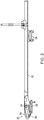
- FIG. 1 is a bicycle 10 mounted to a load carrier 16 by an anchor 20 configured for releasably securing the bicycle through-axle 14 that is installed in the wheelless front fork 12 of the bicycle.
- FIG. 2 discloses the same load carrier 16 having anchor 20 without a bicycle installed therein.
- the anchor 20 includes a through-axle receiving space 24 for receiving a bicycle through-axle therein, as well as brackets 28 for attaching the load carrier to a load bar such as a vehicle cross-bar.
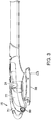
- FIG. 3 illustrates one embodiment of the anchor 20.
- the anchor 20 comprises (includes, but is not limited to) an anchor body 22 comprising a through-axle receiving space 24 for receiving a bicycle through-axle therein.
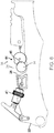
- FIG. 4 illustrates one example of the anchor 20 with outer housing removed to show internal components. Shown is a movable jaw 30 located within the anchor body 22, which is transitionable between a receiving configuration and a secured configuration. Movable jaw 30 is illustrated in FIG. 4 positioned in a receiving configuration 32 in which an interior 26 of the receiving space 24 is expanded for insertably receiving the bicycle through-axle 14 therein.
- FIG. 5 illustrates anchor 20 in a secured configuration 34 in which the movable jaw 30 is in lateral abutting engagement with the bicycle through-axle 14 received within the interior 26 of the receiving space 24.
- lateral abutting engagement it is meant that the movable jaw 30 approaches the through-axle 14 from its side when transitioning from the receiving configuration 32 to the secured configuration 34, and ultimately presses thereagainst for trapping the through-axle 14 in the interior 26 of the receiving space 24. That is, the movable jaw 30 approaches the bicycle through-axle 14 received within the interior 26 of the receiving space 24 from its side, in a substantially horizontal direction, and thereby affects lateral abutting engagement of the movable jaw 30 on the bicycle through-axle 14.
- the through-axle receiving space 24 has a variably configurable interior 26 for receiving different sized bicycle through-axles 14 therein.
- variably configurable it is meant that the interior 26 of the receiving space 24 can be made to have at least different sizes, and potentially other dimensions as well, in the receiving configuration 32.
- the particular size and/or configuration of the interior 26 of the receiving space 24 depends upon the size (and shape) of the through-axle 14 intended to be installed therein for securement.
- a back-stop 36 is located within the anchor body 22 and positioned adjacent to the through-axle receiving space 24.
- the back-stop 36 has a mating portion that fits about differently sized bicycle through-axles when abuttingly engaged thereagainst.
- FIG. 6 illustrates an anchor 20 wherein back-stop 36 serves as a macro-adjuster 42 located within the anchor body 22 and positioned adjacent to the through-axle receiving space 24 in at least one exemplary embodiment.
- the macro-adjuster 42 comprises a plurality (two or more) recessed profiles 44 and 45 that each individually conformance fits to different sized bicycle through-axle 14 when abuttingly engaged thereagainst.
- the macro-adjuster 42 is a round, rotatable disk is provided with different sized recesses located about its perimeter.
- Each recess is semi-circular with a diameter approximately equal to that of the through-axle 14 against which it is intended to abut.
- the disc can be rotated into different positions directing the particular recess toward the interior 26 of the receiving space 24 that is sized to mate with the intended through-axle 14.
- FIG. 7 illustrates an alternative embodiment of an anchor 20 wherein movable jaw 30 serves as a macro-adjuster 43 located within the anchor body 22 adjacent to the through-axle receiving space 24.
- the macro-adjuster 43 comprises a plurality (two or more) recessed profiles 47 and 49 that each individually conformance fits to different sized bicycle through-axle 14 when abuttingly engaged thereagainst.
- the macro-adjuster 43 is rotatable to provide different sized recess located about its perimeter for abutment against different sized bicycle through-axle 14. Each recess is semi-circular with a diameter approximately equal to that of the through-axle 14 against which it is intended to abut.
- the disc can be rotated into different positions directing the particular recess toward the interior 26 of the receiving space 24 that is sized to mate with the intended through-axle 14.
- an actuator 46 is coupled to (interconnected with, but not necessarily directly) the movable jaw 30 that transitions the movable jaw 30 between the receiving 32 and secured 34 configurations.
- the through-axle receiving space 26 laterally bounds any bicycle through-axle 14 inserted therein when the movable jaw 30 is in the secured configuration 34.
- laterally bound it is meant that sidewalls of the receiving space 26 are at least as tall as the through-axle 14 received therein in both the receiving 32 and securing 34 configurations. It is possible, however, that the receiving space 24 can be open above the received through-axle 14.
- An adjuster 40 is located within the anchor body 22 and is variably configurable for varying the size of the interior 26 of the through-axle receiving space 24.
- the actuator 46 includes a micro-adjuster 48 located within the anchor body 22 and which is variably adjustable for controlling a press-force exerted on a bicycle through-axle 14 in the secured configuration.
- the micro-adjuster 48 is a threaded turnbuckle 52 that extends and retracts upon actuation.
- the actuator 46 comprises a first lever 60 coupled to the movable jaw 30 that translates the movable jaw 30 between the receiving 32 and secured 34 configurations.
- a second lever 70 abuttingly engages a lever arm 62 of the first lever 60 during actuation and the second lever 70 forms a cover over the through-axle receiving space 24 in a fully actuated configuration of the second lever 70.
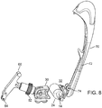
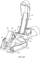
- FIG. 8 illustrates second lever 70 in a raised position, and where the moveable jaw 30 is in the receiving configuration 32.
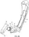
- FIG. 8A illustrates a perspective view of the anchor 20 with the second lever 70 in the same position as in FIG. 8 but with body 22.
- FIG. 8B illustrates the same in a perspective view, and with body 22 invisible.
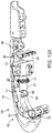
- FIG. 9 illustrates second lever 70 abuttingly engaging the lever arm 62 midway along second lever 70. Accordingly, a motive force is applied to the lever arm 62 by second lever 70.
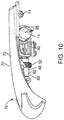
- the first lever 60 translates the movable jaw 30 to the secured configuration 34, as shown in FIG. 10 .
- the second lever 70 forms a cover over the through-axle receiving space 24.
- FIG. 10A illustrates the same secured configuration with lever 70 acting as a cover but with a perspective view from a vantage point below the anchor 20.
- a lock 80 (e.g. shown in FIG. 2 ) can be provided that retains the movable jaw 30 in the secured configuration 34 until the lock 80 is unlocked for authorized release of the bicycle through-axle 14 and dismount of the bicycle 10 from the incorporating load carrier 16.
- the lock 80 releasably secures the second lever 70 over the through-axle receiving space 24 in the fully actuated configuration of the second lever 70.
- the first lever 60 is a second order lever having a first lever arm 62 that is journaled to the anchor body 22 at a first end 64 of the first lever 60.
- the fulcrum is located at one end of the lever arm, the motive force is applied at the other end of the arm and the load to be moved or otherwise urged engages the arm therebetween.
- the second lever 70 is a second order lever having a second lever arm 72 that is journaled to the anchor body 22 at a first end 74 of the second lever 70. The second lever arm 72 abuttingly engages the first lever arm 62 at a mid-point (mid-range) along a length of the second lever arm 72.
- the actuator 46 comprises a first lever 60 coupled to the movable jaw 30 that linearly translates the movable jaw 30 across a support surface between the receiving 32 and secured 34 configurations.
- the actuator comprises a biasing member acting upon the first lever 60 coupled to the movable jaw 30 and which retracts the movable jaw 30 into the receiving configuration 32 from the secured configuration 34.
- a first lever arm 62 of the first lever 60 coupled to the movable jaw 30 comprises two arm extensions 66 journaled together and configured so that the lever arm 62 buckles in an over-center orientation in the secured configuration 34 of the movable jaw 30 thereby holding the movable jaw 30 in the secured configuration 34 until the two arm extensions 66 are transitioned out of the over-center orientation.
- the actuator 46 can also include a second lever 70 that abuttingly engages the lever arm 62 of the first lever 60 during actuation, the second lever 70 forming a cover 76 over the through-axle receiving space 24 in a fully actuated configuration of the second lever 70.
- the actuator 46 comprises a compound lever 54 that includes a first lever 60 and a second lever 70, illustrated in FIG. 9 .
- One lever 60 of the compound lever 54 is coupled to the movable jaw 30.
- At least one of the levers 60, 70 is a second order lever and that lever is coupled to the movable jaw 30.
- the second order lever is coupled to the movable jaw 30 by a turnbuckle 52 (threaded) that is journaled to a lever arm 62 of the second order lever at a first end of the turnbuckle 52 and the turnbuckle 52 is journaled to the movable jaw 30 at a second end of the turnbuckle 52 that is opposite to the first end of the turnbuckle 52.
- the actuator 46 comprises a first lever 60, coupled to the movable jaw 30, that pivotably translates the jaw 30 between the receiving 32 and secured 34 configurations.
- the actuator 46 comprises a second lever 70 that abuttingly engages a lever arm 62 of the first lever 60 during actuation and the second lever 70 forms a cover 76 over the through-axle receiving space 24 in a fully actuated configuration of the second lever 70.
- a bicycle through-axle engagement profile 31 on the movable jaw 30 is substantially V-shaped for abuttingly engaging differently sized bicycle through-axles 14.
- a cradle 84 is provided on the anchor 20 that is configured to support a bicycle through-axle 14 therein and maintain a bicycle 10 incorporating the bicycle through-axle 14 in an upright position on the anchor 20.
Claims (15)
- Anker (20) zum lösbaren Sichern einer Fahrradsteckachse (14), die in einer Vordergabel (12) eines Fahrrads (10) ohne Rad eingebaut ist, an einem Lastträger (16), wobei der Anker (20) Folgendes umfasst:einen Ankerkörper (22), der einen Steckachsen-Aufnahmeraum (24) zum Aufnehmen einer Fahrradsteckachse (14) darin umfasst; undeine bewegliche Backe (30), die innerhalb des Ankerkörpers (22) angeordnet und zwischen einer Aufnahmegestaltung (32), in der ein Innenraum (26) des Aufnahmeraums (24) erweitert ist, damit einschiebbar eine Fahrradsteckachse (14) darin aufgenommen wird, und einer gesicherten Gestaltung (34) wandelbar ist, in der die bewegliche Backe (30) seitlich anliegend mit einer Fahrradsteckachse (14) in Eingriff befindlich ist, die im Innenraum (26) des Aufnahmeraums (24) aufgenommen ist, undein mit der beweglichen Backe (30) verbundenes Betätigungselement (46), das die bewegliche Backe (30) zwischen der Aufnahmegestaltung (32) und der gesicherten Gestaltung (34) wechseln lässt, und wobei der Steckachsen-Aufnahmeraum (24) seitlich eine darin eingeschobene Fahrradsteckachse (14) begrenzt, wenn sich die bewegliche Backe (30) in der gesicherten Gestaltung (34) befindet,dadurch gekennzeichnet, dass
das Betätigungselement (46) einen mit der beweglichen Backe (30) verbundenen ersten Hebel (60) umfasst, der die bewegliche Backe (30) geradlinig verschiebbar über eine Auflagefläche des Ankerkörpers (22) zwischen der Aufnahmegestaltung (32) und der gesicherten Gestaltung (34) bewegt. - Anker (20) nach Anspruch 1, wobei sich die bewegliche Backe (30) von der Seite her, in einer im Wesentlichen waagerechten Richtung, auf die Fahrradsteckachse (14), die im Innenraum (26) des Aufnahmeraums (24) aufgenommen ist, zu bewegt und dadurch einen seitlichen Anlageeingriff der beweglichen Backe (30) an der Fahrradsteckachse (14) beeinflusst.
- Anker (20) nach Anspruch 1, der ferner beinhaltet, dass der Steckachsen-Aufnahmeraum (24) einen veränderlich gestaltbaren Innenraum (26) zum Aufnehmen unterschiedlich großer Fahrradsteckachsen (14) darin aufweist.
- Anker (20) nach Anspruch 3, ferner umfassend:ein Makroeinstellelement (42), das sich innerhalb des Ankerkörpers (22) befindet und angrenzend an den Steckachsen-Aufnahmeraum (24) platziert ist, wobei das Makroeinstellelement (42) eine Vielzahl von versenkten Profilen (44) umfasst, die jeweils passgenau zu unterschiedlich großen Fahrradsteckachsen (14) passen, wenn sie anliegend daran in Eingriff befindlich sind.
- Anker (20) nach Anspruch 3, ferner umfassend:ein Makroeinstellelement (42), das sich im Ankerkörper (22) befindet und angrenzend an den Steckachsen-Aufnahmeraum (24) platziert ist, wobei das Makroeinstellelement (42) ein versenktes Profil (44) umfasst, das so gestaltet ist, dass es um einen Teil einer Fahrradsteckachse (14) mit einer bestimmten Größe herum passgenau passt, wenn es anliegend daran in Eingriff befindlich ist.
- Anker (20) nach Anspruch 1, ferner umfassend:einen Anschlag (36), der sich innerhalb des Ankerkörpers (22) befindet und angrenzend an den Steckachsen-Aufnahmeraum (24) platziert ist, wobei der Anschlag (36) einen Passabschnitt umfasst, der um unterschiedlich große Fahrradsteckachsen (14) passt, wenn er anliegend daran in Eingriff befindlich ist.
- Anker (20) nach Anspruch 1, wobei das Betätigungselement (46) Folgendes umfasst:ein Mikroeinstellelement (48), das sich innerhalb des Ankerkörpers (22) befindet und veränderlich einstellbar ist, damit es eine auf eine Fahrradsteckachse (14) in der gesicherten Gestaltung (34) ausgeübte Presskraft steuert.
- Anker (20) nach Anspruch 7, wobei das Mikroeinstellelement (48) eine mit Gewinde versehene Spannvorrichtung (52) ist, die sich bei Betätigung verlängert und verkürzt.
- Anker (20) nach Anspruch 1, wobei das Betätigungselement (46) Folgendes umfasst:ein Einstellelement (40), das sich innerhalb des Ankerkörpers (22) befindet und veränderlich konfigurierbar ist, damit die Größe des Innenraums (26) des Steckachsen-Aufnahmeraums (24) verändert wird.
- Anker (20) nach Anspruch 1, wobei das Betätigungselement (46) Folgendes umfasst:einen mit der beweglichen Backe (30) verbundenen ersten Hebel (60), der die bewegliche Backe (30) zwischen der Aufnahmegestaltung (32) und der gesicherten Gestaltung (34) bewegt; undeinen zweiten Hebel (70), der während der Betätigung mit einem Hebelarm (62) des ersten Hebels (60) anliegend in Eingriff befindlich ist, wobei der zweite Hebel (70) in einer vollständig betätigten Gestaltung des zweiten Hebels (70) eine Abdeckung (76) über dem Steckachsen-Aufnahmeraum (24) bildet.
- Anker (20) nach Anspruch 10, wobei der erste Hebel (60) ein Hebel zweiter Ordnung mit einem ersten Hebelarm (62) ist, der an einem ersten Ende (64) des ersten Hebels (60) drehbar am Ankerkörper (22) gelagert ist, und der zweite Hebel (70) ein Hebel zweiter Ordnung mit einem zweiten Hebelarm (72) ist, der an einem ersten Ende (74) des zweiten Hebels (70) drehbar am Ankerkörper (22) gelagert ist, und der zweite Hebelarm (72) mit dem ersten Hebelarm (62) an einem Punkt mittig entlang einer Länge des zweiten Hebelarms (72) anliegend in Eingriff befindlich ist.
- Anker (20) nach Anspruch 1, wobei das Betätigungselement (46) ein Vorspannelement umfasst, das auf den ersten Hebel (60) wirkt, der mit der beweglichen Backe (30) verbunden ist, und die bewegliche Backe (30) aus der gesicherten Gestaltung (34) in die Aufnahmegestaltung (32) zurückzieht.
- Anker (20) nach Anspruch 1, wobei ein Hebelarm (62) des ersten Hebels (60), der mit der beweglichen Backe (30) verbunden ist, zwei miteinander drehbar gelagerte Armverlängerungen (66) umfasst, wodurch der Hebelarm (62) in einer Übertotpunktausrichtung in der gesicherten Gestaltung (34) der beweglichen Backe (30) einknickt und dadurch die bewegliche Backe (30) in der gesicherten Gestaltung (34) hält, bis die beiden Armverlängerungen (66) aus der Übertotpunktausrichtung gebracht werden.
- Anker (20) nach Anspruch 1, wobei das Betätigungselement (46) einen zweiten Hebel (70) umfasst, der während der Betätigung mit dem Hebelarm (62) des ersten Hebels (60) anliegend in Eingriff befindlich ist, wobei der zweite Hebel (70) in einer vollständig betätigten Gestaltung des zweiten Hebels (70) eine Abdeckung (76) über dem Steckachsen-Aufnahmeraum (24) bildet.
- Anker (20) nach Anspruch 1, wobei ein Fahrradsteckachsen-Eingriffprofil (31) an der beweglichen Backe (30) im Wesentlichen V-förmig ist, damit es mit unterschiedlich großen Fahrradsteckachsen (14) anliegend in Eingriff gelangt.
Applications Claiming Priority (2)
| Application Number | Priority Date | Filing Date | Title |
|---|---|---|---|
| US201361859085P | 2013-07-26 | 2013-07-26 | |
| PCT/US2014/039216 WO2015012952A1 (en) | 2013-07-26 | 2014-05-22 | Anchor on a load carrier for a bicycle through-axle |
Publications (2)
| Publication Number | Publication Date |
|---|---|
| EP3060432A1 EP3060432A1 (de) | 2016-08-31 |
| EP3060432B1 true EP3060432B1 (de) | 2017-08-30 |
Family
ID=51352746
Family Applications (1)
| Application Number | Title | Priority Date | Filing Date |
|---|---|---|---|
| EP14750824.6A Active EP3060432B1 (de) | 2013-07-26 | 2014-05-22 | Anker oder lastträger für eine fahrraddurchgangsachse |
Country Status (5)
| Country | Link |
|---|---|
| US (1) | US9376065B2 (de) |
| EP (1) | EP3060432B1 (de) |
| CN (1) | CN105452062B (de) |
| CA (1) | CA2919148C (de) |
| WO (1) | WO2015012952A1 (de) |
Families Citing this family (6)
| Publication number | Priority date | Publication date | Assignee | Title |
|---|---|---|---|---|
| EP2977269B1 (de) | 2014-07-25 | 2016-06-01 | Thule Sweden AB | Einstellbarer anker auf einem lastträger für eine fahrraddurchgangsachse |
| US9738231B2 (en) | 2015-07-24 | 2017-08-22 | Thule Sweden Ab | Bicycle carriers and skewer assemblies |
| WO2017214066A1 (en) * | 2016-06-05 | 2017-12-14 | Yakima Products, Inc. | Fork-mount bicycle carrier |
| US10857949B2 (en) | 2017-04-18 | 2020-12-08 | Yakima Products, Inc. | Fork mount bicycle carrier |
| DE102017219039A1 (de) * | 2017-10-25 | 2019-04-25 | Atera Gmbh | Trägereinheit für eine Dachträgeranordnung eines Kraftfahrzeugs |
| EP3838678B1 (de) * | 2019-12-20 | 2022-04-27 | Thule Sweden AB | Trageinheit für einen fahrradträger |
Family Cites Families (29)
| Publication number | Priority date | Publication date | Assignee | Title |
|---|---|---|---|---|
| US764774A (en) * | 1903-09-04 | 1904-07-12 | John Frederick Sargeant | Bicycle or cycle holder. |
| FR2332155A1 (fr) | 1975-11-21 | 1977-06-17 | Busset Jacques | Porte-bicyclette perfectionne adaptable sur les galeries porte-bagages et similaires montees sur le toit des vehicules automobiles |
| FR2551705A1 (fr) * | 1983-09-12 | 1985-03-15 | Macorex Exploit Ets | Porte-bicyclette destine a equiper les barres porte-bagages d'un vehicule automobile |
| US5417629A (en) | 1991-10-31 | 1995-05-23 | Phipps; Gary G. B. | Axle mounting bicycle stand and carrier |
| US5362173A (en) * | 1992-09-17 | 1994-11-08 | Industri Ab Thule | Lockable quick release mechanism |
| US5598959A (en) * | 1995-07-06 | 1997-02-04 | Yakima Products | Article-carrying rack with lockable mount |
| US5875947A (en) | 1996-10-21 | 1999-03-02 | Industri Ab Thule | Centralized handled bicycle fork anchor |
| TW392631U (en) * | 1999-01-29 | 2000-06-01 | Errow Drew | Improved structure for bicycle retaining rack |
| US6283310B1 (en) * | 1999-11-23 | 2001-09-04 | Yakima Products, Inc. | Bicycle carrier |
| US6494351B1 (en) | 2000-05-31 | 2002-12-17 | Yakima Products, Inc. | Bicycle carrier |
| US20030080267A1 (en) | 2001-10-29 | 2003-05-01 | Panavision, Inc. | Multi-sized clamp |
| US6758380B1 (en) | 2002-04-09 | 2004-07-06 | Graber Products, Inc. | Locking fork mount for a bicycle carrier |
| SE0201832L (sv) * | 2002-06-14 | 2003-09-30 | Thule Sweden Ab | Lasthållare för transport av en cykel |
| US6913234B2 (en) | 2002-10-07 | 2005-07-05 | Sondra Weiss | Rod clamp |
| WO2007027295A2 (en) * | 2005-07-12 | 2007-03-08 | Michael Grim | Through-axle bicycle fork mounting clamp |
| WO2007022274A2 (en) | 2005-08-15 | 2007-02-22 | Thule, Inc. | Load carrier for securing bicycle fork assemblies |
| US8136709B2 (en) | 2006-01-23 | 2012-03-20 | Yakima Products, Inc. | Article carriers |
| AU2007296750B2 (en) | 2006-09-14 | 2013-01-17 | Indiana Mills & Manufacturing, Inc. | Apparatus, method and system for restraining an object in a vehicle |
| US7815083B2 (en) * | 2006-10-27 | 2010-10-19 | Softride, Inc. | Hitch mounted carrier |
| US7665928B2 (en) | 2007-04-05 | 2010-02-23 | Crank Brothers, Inc. | Quick release camming mechanism |
| DE102007052039B3 (de) | 2007-10-30 | 2009-06-10 | FLM GMBH FOTO-, LICHT- UND MEßTECHNISCHES ZUBEHÖR | Stativkopf |
| US8393506B2 (en) * | 2007-11-21 | 2013-03-12 | Thule Sweden Ab | Bicycle support assembly for use with a load carrier for vehicles |
| CN101279623B (zh) * | 2008-05-13 | 2011-08-03 | 李明谊 | 车载自行车固定架 |
| TW201111201A (en) * | 2009-06-05 | 2011-04-01 | Yakima Products Inc | Upright bike mount |
| US20100314517A1 (en) | 2009-06-12 | 2010-12-16 | Smiths Medical Asd, Inc. | Pole Clamp |
| WO2010144749A1 (en) | 2009-06-12 | 2010-12-16 | Yakima Products, Inc. | Skewer assembly for bicycle fork mount |
| TWI594906B (zh) | 2009-06-15 | 2017-08-11 | 亞奇瑪產品公司 | 橫桿夾持裝置 |
| DE102009039820A1 (de) | 2009-09-02 | 2011-03-03 | Westfalia-Automotive Gmbh | Befestigungseinrichtung mit einer Schelle |
| US8403280B2 (en) | 2010-08-25 | 2013-03-26 | Shure Acquisition Holdings, Inc. | Microphone mounting apparatus |
-
2014
- 2014-05-22 EP EP14750824.6A patent/EP3060432B1/de active Active
- 2014-05-22 CA CA2919148A patent/CA2919148C/en active Active
- 2014-05-22 WO PCT/US2014/039216 patent/WO2015012952A1/en active Application Filing
- 2014-05-22 CN CN201480042258.6A patent/CN105452062B/zh active Active
- 2014-07-25 US US14/341,524 patent/US9376065B2/en active Active
Non-Patent Citations (1)
| Title |
|---|
| None * |
Also Published As
| Publication number | Publication date |
|---|---|
| CA2919148A1 (en) | 2015-01-29 |
| CN105452062B (zh) | 2017-09-15 |
| CN105452062A (zh) | 2016-03-30 |
| WO2015012952A1 (en) | 2015-01-29 |
| US20150028076A1 (en) | 2015-01-29 |
| CA2919148C (en) | 2019-10-01 |
| EP3060432A1 (de) | 2016-08-31 |
| US9376065B2 (en) | 2016-06-28 |
Similar Documents
| Publication | Publication Date | Title |
|---|---|---|
| EP3060432B1 (de) | Anker oder lastträger für eine fahrraddurchgangsachse | |
| US10442364B2 (en) | Adjustable anchor on a load carrier for a bicycle through-axle | |
| EP1934086B1 (de) | Lastträger zur befestigung von fahrradgabelanordnungen | |
| EP1851160B1 (de) | Wartungs- und reparaturhebeplattform für leichtfahrzeuge | |
| EP2596966B1 (de) | Anhängerkupplungsanordnung für Zugkraftfahrzeug | |
| EP2678194A1 (de) | Halterung für einen sicherheitsgurtaufroller | |
| EP2022682A1 (de) | Karosseriestruktur eines Kraftfahrzeugs und eine solche Karosseriestruktur umfassendes Kraftfahrzeug | |
| FR2887836A1 (fr) | Verrou pour solidariser une extremite spherique de commande de frein a un poussoir de pedale de frein de vehicule automobile | |
| CA2466388A1 (en) | An improved vehicle rack | |
| FR3035387A1 (fr) | Dispositif de blocage de vehicule utilitaire devant un quai de transbordement | |
| US7959389B2 (en) | Vehicle tiedown systems and methods of use | |
| EP0272192B1 (de) | Einheitlicher Tragarm zum Stützen eines Fahrzeuges mittels seiner Räder | |
| EP3177467B1 (de) | Reihe von wagen mit schleppkonfiguration | |
| FR2990168A1 (fr) | Siege, notamment pour vehicule automobile | |
| WO2016030592A1 (fr) | Porte moyeu de roue de vehicule | |
| EP3162614B1 (de) | Sitz für fahrzeug, der einen begrenzungsmechanismus für das verschieben hat | |
| EP3124328B1 (de) | Dachlastenträger | |
| FR2827363A1 (fr) | Agrafe et procede de clippage d'elements fonctionnels | |
| WO2016198768A1 (fr) | Remorque semi articulée destinée à être attelée à un véhicule tracteur et ensemble attelé comprenant une telle remorque | |
| EP4321384A1 (de) | Lastenträger für ein kraftfahrzeug | |
| EP2923863A1 (de) | Diebstahlsicherungsvorrichtung für Anhängerkupplung | |
| EP2380797B1 (de) | Lenksäule mit teleskopischem Einstellmechanismus und/oder Energieabsorptionsfunktion beim Zurückziehen | |
| FR2981607A1 (fr) | Dispositif de fixation d'un objet embarque a l'arriere d'un vehicule | |
| FR3055274A1 (fr) | Support de velo arriere | |
| FR3030389A1 (fr) | Sieges de vehicule de 2eme rang prevus pour faciliter l'acces au 3eme rang, un moyen de deverrouillage permettant en une seule action d'escamoter simultanement un siege lateral et le siege central |
Legal Events
| Date | Code | Title | Description |
|---|---|---|---|
| PUAI | Public reference made under article 153(3) epc to a published international application that has entered the european phase |
Free format text: ORIGINAL CODE: 0009012 |
|
| 17P | Request for examination filed |
Effective date: 20160701 |
|
| AK | Designated contracting states |
Kind code of ref document: A1 Designated state(s): AL AT BE BG CH CY CZ DE DK EE ES FI FR GB GR HR HU IE IS IT LI LT LU LV MC MK MT NL NO PL PT RO RS SE SI SK SM TR |
|
| AX | Request for extension of the european patent |
Extension state: BA ME |
|
| DAX | Request for extension of the european patent (deleted) | ||
| GRAP | Despatch of communication of intention to grant a patent |
Free format text: ORIGINAL CODE: EPIDOSNIGR1 |
|
| INTG | Intention to grant announced |
Effective date: 20170531 |
|
| GRAS | Grant fee paid |
Free format text: ORIGINAL CODE: EPIDOSNIGR3 |
|
| GRAA | (expected) grant |
Free format text: ORIGINAL CODE: 0009210 |
|
| AK | Designated contracting states |
Kind code of ref document: B1 Designated state(s): AL AT BE BG CH CY CZ DE DK EE ES FI FR GB GR HR HU IE IS IT LI LT LU LV MC MK MT NL NO PL PT RO RS SE SI SK SM TR |
|
| REG | Reference to a national code |
Ref country code: GB Ref legal event code: FG4D |
|
| REG | Reference to a national code |
Ref country code: CH Ref legal event code: EP |
|
| REG | Reference to a national code |
Ref country code: AT Ref legal event code: REF Ref document number: 923189 Country of ref document: AT Kind code of ref document: T Effective date: 20170915 |
|
| REG | Reference to a national code |
Ref country code: IE Ref legal event code: FG4D |
|
| REG | Reference to a national code |
Ref country code: DE Ref legal event code: R096 Ref document number: 602014013889 Country of ref document: DE |
|
| REG | Reference to a national code |
Ref country code: NL Ref legal event code: MP Effective date: 20170830 |
|
| REG | Reference to a national code |
Ref country code: LT Ref legal event code: MG4D |
|
| REG | Reference to a national code |
Ref country code: AT Ref legal event code: MK05 Ref document number: 923189 Country of ref document: AT Kind code of ref document: T Effective date: 20170830 |
|
| PG25 | Lapsed in a contracting state [announced via postgrant information from national office to epo] |
Ref country code: AT Free format text: LAPSE BECAUSE OF FAILURE TO SUBMIT A TRANSLATION OF THE DESCRIPTION OR TO PAY THE FEE WITHIN THE PRESCRIBED TIME-LIMIT Effective date: 20170830 Ref country code: LT Free format text: LAPSE BECAUSE OF FAILURE TO SUBMIT A TRANSLATION OF THE DESCRIPTION OR TO PAY THE FEE WITHIN THE PRESCRIBED TIME-LIMIT Effective date: 20170830 Ref country code: SE Free format text: LAPSE BECAUSE OF FAILURE TO SUBMIT A TRANSLATION OF THE DESCRIPTION OR TO PAY THE FEE WITHIN THE PRESCRIBED TIME-LIMIT Effective date: 20170830 Ref country code: FI Free format text: LAPSE BECAUSE OF FAILURE TO SUBMIT A TRANSLATION OF THE DESCRIPTION OR TO PAY THE FEE WITHIN THE PRESCRIBED TIME-LIMIT Effective date: 20170830 Ref country code: NO Free format text: LAPSE BECAUSE OF FAILURE TO SUBMIT A TRANSLATION OF THE DESCRIPTION OR TO PAY THE FEE WITHIN THE PRESCRIBED TIME-LIMIT Effective date: 20171130 Ref country code: HR Free format text: LAPSE BECAUSE OF FAILURE TO SUBMIT A TRANSLATION OF THE DESCRIPTION OR TO PAY THE FEE WITHIN THE PRESCRIBED TIME-LIMIT Effective date: 20170830 |
|
| PG25 | Lapsed in a contracting state [announced via postgrant information from national office to epo] |
Ref country code: IS Free format text: LAPSE BECAUSE OF FAILURE TO SUBMIT A TRANSLATION OF THE DESCRIPTION OR TO PAY THE FEE WITHIN THE PRESCRIBED TIME-LIMIT Effective date: 20171230 Ref country code: LV Free format text: LAPSE BECAUSE OF FAILURE TO SUBMIT A TRANSLATION OF THE DESCRIPTION OR TO PAY THE FEE WITHIN THE PRESCRIBED TIME-LIMIT Effective date: 20170830 Ref country code: RS Free format text: LAPSE BECAUSE OF FAILURE TO SUBMIT A TRANSLATION OF THE DESCRIPTION OR TO PAY THE FEE WITHIN THE PRESCRIBED TIME-LIMIT Effective date: 20170830 Ref country code: ES Free format text: LAPSE BECAUSE OF FAILURE TO SUBMIT A TRANSLATION OF THE DESCRIPTION OR TO PAY THE FEE WITHIN THE PRESCRIBED TIME-LIMIT Effective date: 20170830 Ref country code: GR Free format text: LAPSE BECAUSE OF FAILURE TO SUBMIT A TRANSLATION OF THE DESCRIPTION OR TO PAY THE FEE WITHIN THE PRESCRIBED TIME-LIMIT Effective date: 20171201 Ref country code: BG Free format text: LAPSE BECAUSE OF FAILURE TO SUBMIT A TRANSLATION OF THE DESCRIPTION OR TO PAY THE FEE WITHIN THE PRESCRIBED TIME-LIMIT Effective date: 20171130 |
|
| PG25 | Lapsed in a contracting state [announced via postgrant information from national office to epo] |
Ref country code: NL Free format text: LAPSE BECAUSE OF FAILURE TO SUBMIT A TRANSLATION OF THE DESCRIPTION OR TO PAY THE FEE WITHIN THE PRESCRIBED TIME-LIMIT Effective date: 20170830 |
|
| PG25 | Lapsed in a contracting state [announced via postgrant information from national office to epo] |
Ref country code: DK Free format text: LAPSE BECAUSE OF FAILURE TO SUBMIT A TRANSLATION OF THE DESCRIPTION OR TO PAY THE FEE WITHIN THE PRESCRIBED TIME-LIMIT Effective date: 20170830 Ref country code: CZ Free format text: LAPSE BECAUSE OF FAILURE TO SUBMIT A TRANSLATION OF THE DESCRIPTION OR TO PAY THE FEE WITHIN THE PRESCRIBED TIME-LIMIT Effective date: 20170830 Ref country code: RO Free format text: LAPSE BECAUSE OF FAILURE TO SUBMIT A TRANSLATION OF THE DESCRIPTION OR TO PAY THE FEE WITHIN THE PRESCRIBED TIME-LIMIT Effective date: 20170830 Ref country code: PL Free format text: LAPSE BECAUSE OF FAILURE TO SUBMIT A TRANSLATION OF THE DESCRIPTION OR TO PAY THE FEE WITHIN THE PRESCRIBED TIME-LIMIT Effective date: 20170830 |
|
| REG | Reference to a national code |
Ref country code: FR Ref legal event code: PLFP Year of fee payment: 5 |
|
| PG25 | Lapsed in a contracting state [announced via postgrant information from national office to epo] |
Ref country code: SM Free format text: LAPSE BECAUSE OF FAILURE TO SUBMIT A TRANSLATION OF THE DESCRIPTION OR TO PAY THE FEE WITHIN THE PRESCRIBED TIME-LIMIT Effective date: 20170830 Ref country code: SK Free format text: LAPSE BECAUSE OF FAILURE TO SUBMIT A TRANSLATION OF THE DESCRIPTION OR TO PAY THE FEE WITHIN THE PRESCRIBED TIME-LIMIT Effective date: 20170830 Ref country code: EE Free format text: LAPSE BECAUSE OF FAILURE TO SUBMIT A TRANSLATION OF THE DESCRIPTION OR TO PAY THE FEE WITHIN THE PRESCRIBED TIME-LIMIT Effective date: 20170830 |
|
| REG | Reference to a national code |
Ref country code: DE Ref legal event code: R097 Ref document number: 602014013889 Country of ref document: DE |
|
| PLBE | No opposition filed within time limit |
Free format text: ORIGINAL CODE: 0009261 |
|
| STAA | Information on the status of an ep patent application or granted ep patent |
Free format text: STATUS: NO OPPOSITION FILED WITHIN TIME LIMIT |
|
| 26N | No opposition filed |
Effective date: 20180531 |
|
| PG25 | Lapsed in a contracting state [announced via postgrant information from national office to epo] |
Ref country code: SI Free format text: LAPSE BECAUSE OF FAILURE TO SUBMIT A TRANSLATION OF THE DESCRIPTION OR TO PAY THE FEE WITHIN THE PRESCRIBED TIME-LIMIT Effective date: 20170830 |
|
| REG | Reference to a national code |
Ref country code: CH Ref legal event code: PL |
|
| REG | Reference to a national code |
Ref country code: BE Ref legal event code: MM Effective date: 20180531 |
|
| PG25 | Lapsed in a contracting state [announced via postgrant information from national office to epo] |
Ref country code: MC Free format text: LAPSE BECAUSE OF FAILURE TO SUBMIT A TRANSLATION OF THE DESCRIPTION OR TO PAY THE FEE WITHIN THE PRESCRIBED TIME-LIMIT Effective date: 20170830 |
|
| REG | Reference to a national code |
Ref country code: IE Ref legal event code: MM4A |
|
| PG25 | Lapsed in a contracting state [announced via postgrant information from national office to epo] |
Ref country code: CH Free format text: LAPSE BECAUSE OF NON-PAYMENT OF DUE FEES Effective date: 20180531 Ref country code: LI Free format text: LAPSE BECAUSE OF NON-PAYMENT OF DUE FEES Effective date: 20180531 |
|
| PG25 | Lapsed in a contracting state [announced via postgrant information from national office to epo] |
Ref country code: LU Free format text: LAPSE BECAUSE OF NON-PAYMENT OF DUE FEES Effective date: 20180522 |
|
| PG25 | Lapsed in a contracting state [announced via postgrant information from national office to epo] |
Ref country code: IE Free format text: LAPSE BECAUSE OF NON-PAYMENT OF DUE FEES Effective date: 20180522 |
|
| PG25 | Lapsed in a contracting state [announced via postgrant information from national office to epo] |
Ref country code: BE Free format text: LAPSE BECAUSE OF NON-PAYMENT OF DUE FEES Effective date: 20180531 |
|
| PG25 | Lapsed in a contracting state [announced via postgrant information from national office to epo] |
Ref country code: MT Free format text: LAPSE BECAUSE OF NON-PAYMENT OF DUE FEES Effective date: 20180522 |
|
| PG25 | Lapsed in a contracting state [announced via postgrant information from national office to epo] |
Ref country code: TR Free format text: LAPSE BECAUSE OF FAILURE TO SUBMIT A TRANSLATION OF THE DESCRIPTION OR TO PAY THE FEE WITHIN THE PRESCRIBED TIME-LIMIT Effective date: 20170830 |
|
| PG25 | Lapsed in a contracting state [announced via postgrant information from national office to epo] |
Ref country code: PT Free format text: LAPSE BECAUSE OF FAILURE TO SUBMIT A TRANSLATION OF THE DESCRIPTION OR TO PAY THE FEE WITHIN THE PRESCRIBED TIME-LIMIT Effective date: 20170830 |
|
| PG25 | Lapsed in a contracting state [announced via postgrant information from national office to epo] |
Ref country code: HU Free format text: LAPSE BECAUSE OF FAILURE TO SUBMIT A TRANSLATION OF THE DESCRIPTION OR TO PAY THE FEE WITHIN THE PRESCRIBED TIME-LIMIT; INVALID AB INITIO Effective date: 20140522 Ref country code: CY Free format text: LAPSE BECAUSE OF FAILURE TO SUBMIT A TRANSLATION OF THE DESCRIPTION OR TO PAY THE FEE WITHIN THE PRESCRIBED TIME-LIMIT Effective date: 20170830 Ref country code: MK Free format text: LAPSE BECAUSE OF NON-PAYMENT OF DUE FEES Effective date: 20170830 |
|
| PG25 | Lapsed in a contracting state [announced via postgrant information from national office to epo] |
Ref country code: AL Free format text: LAPSE BECAUSE OF FAILURE TO SUBMIT A TRANSLATION OF THE DESCRIPTION OR TO PAY THE FEE WITHIN THE PRESCRIBED TIME-LIMIT Effective date: 20170830 |
|
| PGFP | Annual fee paid to national office [announced via postgrant information from national office to epo] |
Ref country code: IT Payment date: 20220519 Year of fee payment: 9 Ref country code: GB Payment date: 20220524 Year of fee payment: 9 |
|
| P01 | Opt-out of the competence of the unified patent court (upc) registered |
Effective date: 20230528 |
|
| PGFP | Annual fee paid to national office [announced via postgrant information from national office to epo] |
Ref country code: FR Payment date: 20230523 Year of fee payment: 10 Ref country code: DE Payment date: 20230530 Year of fee payment: 10 |
|
| GBPC | Gb: european patent ceased through non-payment of renewal fee |
Effective date: 20230522 |
|
| PG25 | Lapsed in a contracting state [announced via postgrant information from national office to epo] |
Ref country code: IT Free format text: LAPSE BECAUSE OF NON-PAYMENT OF DUE FEES Effective date: 20230522 Ref country code: GB Free format text: LAPSE BECAUSE OF NON-PAYMENT OF DUE FEES Effective date: 20230522 |