EP3060089B1 - Entfernung von ablagerungen aus heissgetränkautomaten - Google Patents
Entfernung von ablagerungen aus heissgetränkautomaten Download PDFInfo
- Publication number
- EP3060089B1 EP3060089B1 EP14789807.6A EP14789807A EP3060089B1 EP 3060089 B1 EP3060089 B1 EP 3060089B1 EP 14789807 A EP14789807 A EP 14789807A EP 3060089 B1 EP3060089 B1 EP 3060089B1
- Authority
- EP
- European Patent Office
- Prior art keywords
- descaling
- water
- chemicals
- hydraulic circuit
- reservoir
- Prior art date
- Legal status (The legal status is an assumption and is not a legal conclusion. Google has not performed a legal analysis and makes no representation as to the accuracy of the status listed.)
- Active
Links
- 235000012171 hot beverage Nutrition 0.000 title claims description 43
- XLYOFNOQVPJJNP-UHFFFAOYSA-N water Substances O XLYOFNOQVPJJNP-UHFFFAOYSA-N 0.000 claims description 275
- 239000000126 substance Substances 0.000 claims description 189
- 239000007788 liquid Substances 0.000 claims description 20
- 235000013361 beverage Nutrition 0.000 claims description 19
- 238000004891 communication Methods 0.000 claims description 17
- 238000000034 method Methods 0.000 claims description 17
- 239000012530 fluid Substances 0.000 claims description 11
- 238000000926 separation method Methods 0.000 claims description 5
- 230000008878 coupling Effects 0.000 claims description 4
- 238000010168 coupling process Methods 0.000 claims description 4
- 238000005859 coupling reaction Methods 0.000 claims description 4
- 235000016213 coffee Nutrition 0.000 description 21
- 235000013353 coffee beverage Nutrition 0.000 description 21
- 238000005192 partition Methods 0.000 description 15
- 239000013505 freshwater Substances 0.000 description 7
- 238000005406 washing Methods 0.000 description 7
- 239000003795 chemical substances by application Substances 0.000 description 5
- 239000012528 membrane Substances 0.000 description 5
- 230000008569 process Effects 0.000 description 5
- 230000008901 benefit Effects 0.000 description 4
- 235000015114 espresso Nutrition 0.000 description 4
- 238000001802 infusion Methods 0.000 description 3
- 230000005540 biological transmission Effects 0.000 description 2
- 230000000694 effects Effects 0.000 description 2
- 238000004519 manufacturing process Methods 0.000 description 2
- 239000000203 mixture Substances 0.000 description 2
- 238000012986 modification Methods 0.000 description 2
- 230000004048 modification Effects 0.000 description 2
- 238000005086 pumping Methods 0.000 description 2
- 230000009471 action Effects 0.000 description 1
- 230000004913 activation Effects 0.000 description 1
- 230000015572 biosynthetic process Effects 0.000 description 1
- 230000001419 dependent effect Effects 0.000 description 1
- 238000013461 design Methods 0.000 description 1
- 231100001261 hazardous Toxicity 0.000 description 1
- 230000036541 health Effects 0.000 description 1
- 230000008642 heat stress Effects 0.000 description 1
- 238000010438 heat treatment Methods 0.000 description 1
- 239000002245 particle Substances 0.000 description 1
- 238000002360 preparation method Methods 0.000 description 1
- 230000009467 reduction Effects 0.000 description 1
- 230000002441 reversible effect Effects 0.000 description 1
- 239000008237 rinsing water Substances 0.000 description 1
- 238000007789 sealing Methods 0.000 description 1
- 230000035882 stress Effects 0.000 description 1
Images


Classifications
-
- A—HUMAN NECESSITIES
- A47—FURNITURE; DOMESTIC ARTICLES OR APPLIANCES; COFFEE MILLS; SPICE MILLS; SUCTION CLEANERS IN GENERAL
- A47J—KITCHEN EQUIPMENT; COFFEE MILLS; SPICE MILLS; APPARATUS FOR MAKING BEVERAGES
- A47J31/00—Apparatus for making beverages
- A47J31/44—Parts or details or accessories of beverage-making apparatus
- A47J31/60—Cleaning devices
-
- B—PERFORMING OPERATIONS; TRANSPORTING
- B08—CLEANING
- B08B—CLEANING IN GENERAL; PREVENTION OF FOULING IN GENERAL
- B08B9/00—Cleaning hollow articles by methods or apparatus specially adapted thereto
- B08B9/02—Cleaning pipes or tubes or systems of pipes or tubes
- B08B9/027—Cleaning the internal surfaces; Removal of blockages
- B08B9/032—Cleaning the internal surfaces; Removal of blockages by the mechanical action of a moving fluid, e.g. by flushing
- B08B9/0321—Cleaning the internal surfaces; Removal of blockages by the mechanical action of a moving fluid, e.g. by flushing using pressurised, pulsating or purging fluid
-
- C—CHEMISTRY; METALLURGY
- C02—TREATMENT OF WATER, WASTE WATER, SEWAGE, OR SLUDGE
- C02F—TREATMENT OF WATER, WASTE WATER, SEWAGE, OR SLUDGE
- C02F5/00—Softening water; Preventing scale; Adding scale preventatives or scale removers to water, e.g. adding sequestering agents
- C02F5/02—Softening water by precipitation of the hardness
- C02F5/025—Hot-water softening devices
-
- C—CHEMISTRY; METALLURGY
- C02—TREATMENT OF WATER, WASTE WATER, SEWAGE, OR SLUDGE
- C02F—TREATMENT OF WATER, WASTE WATER, SEWAGE, OR SLUDGE
- C02F2303/00—Specific treatment goals
- C02F2303/22—Eliminating or preventing deposits, scale removal, scale prevention
-
- C—CHEMISTRY; METALLURGY
- C02—TREATMENT OF WATER, WASTE WATER, SEWAGE, OR SLUDGE
- C02F—TREATMENT OF WATER, WASTE WATER, SEWAGE, OR SLUDGE
- C02F2307/00—Location of water treatment or water treatment device
- C02F2307/12—Location of water treatment or water treatment device as part of household appliances such as dishwashers, laundry washing machines or vacuum cleaners
Definitions
- the invention concerns improvements to hot-beverage producing machines and devices for such machines. More specifically, the invention concerns improvements to devices and methods for descaling the hydraulic circuit of hot-beverage producing machines.
- Hot-beverage producing machines such as espresso or coffee machines
- These machines comprise a water tank and a hydraulic circuit, comprised of a pump and a water heater or boiler. Water pumped from the tank flows through the heater and is heated up to the required temperature for the production of hot-beverage, for example around 90°C.
- Hot water separates scale, which forms a scale deposit in the water circuit and specifically in the hot section of the circuit, such as the water heater and the ducts and pipes downstream thereof. During use the scale deposit grows on the heating elements of the heater and/or on the water pipes, and will reduce the efficiency of the heater. Internal stresses and heat stresses can cause breaking of the scale and formation of scale particles, which can clog the hydraulic circuit.
- Descaling cycles are usually performed manually by filling the water tank of the hot-beverage producing machine with diluted descaling chemicals. Once the water tank is filled with water-diluted descaling chemicals, the descaling cycle is started. During the descaling cycle the pump of the hydraulic circuit pumps the water-diluted descaling chemicals from the water tank and circulates them through the hydraulic circuit. After flowing through the hydraulic circuit, the water-diluted descaling chemicals and dissolved descaled residues are discharged through the beverage dispensing nozzles, the machine is provided with.
- the water tank must be filled with fresh water.
- the fresh water is pumped through the hydraulic circuit to was the circuit and remove any residues of the descaling chemicals therefrom.
- This washing cycle can be performed once or twice, each time filling the water tank again. Washing the hydraulic circuit is necessary, because the descaling chemicals are non-edible and might be hazardous for the human health.
- the descaling and subsequent washing cycle require the presence of an operator and lasts a rather long time.
- Hot beverage machines also exist, wherein a descaling chemicals container is directly connected to the hydraulic circuit of the machine.
- Suitably controlled valves are provided for selectively flowing water from a water container through the descaling container, or through a brewing unit, bypassing the descaling chemicals container.
- water is pumped by the pump of the hydraulic circuit from the water container directly into a water heater and therefrom towards a brewing unit.
- the descaling chemicals container is bypassed.
- the water path is modified by switching suitably arranged valves, such that water is pumped by the pump from the water container through the descaling chemicals container.
- Descaling chemicals contained in the container are dissolved in water and the descaling solution is circulated in the hydraulic circuit. Once the required amount of descaling solution has been caused to flow through the hydraulic circuit, the valves are switched again to by-pass the descaling chemicals container an fresh water is pumped from the water container directly to and through the water heater.
- WO2009/124786 discloses a further device for descaling a hydraulic circuit in a beverage producing machine.
- the machine includes a water container, a pump, a water heater and a brewing unit.
- a descaling agent reservoir is arranged in-line, between the water container and the pump.
- the operator introduces a water-soluble descaling agent in the reservoir and starts the descaling cycle. Water flows from the water container through the descaling agent reservoir and dissolves the descaling agent.
- the descaling solution circulates in the hydraulic circuit.
- This known device is not particularly user-friendly and requires a complex structure of the water container and descaling agent reservoir.
- the invention concerns a method of descaling the hydraulic circuit of a hot-beverage producing machine, such as a coffee or espresso machine, according to claim 1.
- the method comprises the following steps:
- the descaling process becomes simpler than in prior art machines, since the phases of descaling and subsequent rinsing of the hydraulic circuit are performed in sequence and without the need for the user's intervention.
- further suction operated by the pump of the hydraulic circuit causes clean water to flow from the descaling device through the hydraulic circuit of the hot-beverage producing machine. All the operator needs to do in order to perform a descaling cycle is thus to connect the descaling device to the machine and arrange a sufficiently large container under the beverage dispensing nozzles wherefrom the spent descaling chemicals first and the rinsing water afterwards will be discharged.
- a method of descaling a hydraulic circuit of a hot-beverage producing machine comprising at least a pump and a water heater.
- the method comprises the steps of:
- the sequence of loading the descaling chemicals in the water tank, descaling the circuit, removing the water tank, washing and rinsing the water tank, filling the water tank with fresh water, re-connecting the water tank to the hot-beverage producing machine and causing water to rinse the hydraulic circuit becomes unnecessary. Since the intervention of the user during the descaling/rinsing process is not necessary anymore, the entire process can be performed without the user being present, e.g. at night time.
- the invention concerns a hot-beverage producing machine with a descaling device for descaling a hydraulic circuit of said hot-beverage producing machine according to claim 2.
- the descaling device comprises:
- the water inlet port can be arranged between the top portion and the bottom portion of the descaling-chemicals reservoir, preferably near or at the bottom portion thereof.
- the water flow passage can extend from the inlet port towards the top portion of the descaling-chemicals reservoir.
- the water inlet port and the outlet port of the descaling device are placed in fluid communication through the water flow passage and the descaling-chemicals reservoir, such that water can be sucked through the inlet port, caused to flow through the descaling-chemicals reservoir and discharged through the outlet port upon activation of the pump of the hydraulic circuit provided in the hot-beverage producing machine.
- the pump in the hot-beverage producing machine Upon starting of the descaling cycle, the pump in the hot-beverage producing machine will firstly suck liquid descaling chemicals from the descaling-chemicals reservoir through the hydraulic circuit of the hot-beverage producing machine. Due to the descaling chemicals flowing from the descaling-chemicals reservoir, a pressure drop will be generated in the descaling-chemicals reservoir, sufficient to generate a suction effect between the descaling-chemicals reservoir and the water inlet port. The suction effect will cause the water level in the water flow passage to lift until reaching an aperture near the top portion of the descaling-chemicals reservoir, wherefrom water flows into and through the descaling-chemicals reservoir and therefrom in the hydraulic circuit of the hot-beverage producing machine. The water thus washes and rinses the descaling-chemicals reservoir and the hydraulic circuit, roving chemical residues therefrom.
- a descaling device for descaling a hydraulic circuit of a hot-beverage producing machine, comprising: a descaling-chemicals reservoir provided with: a top portion; a bottom portion; an outlet port having an openable closure member for establishing a flow connection of the descaling-chemicals reservoir with a hydraulic circuit of a hot-beverage producing machine; a water inlet port; a water flow passage for flow communication between the water inlet port and the descaling-chemicals reservoir; wherein the outlet port is arranged at or near the bottom portion and the water inlet port is arranged between the top portion and the bottom portion; wherein the water flow passage extends from the water inlet port towards the top portion; and wherein the water inlet port and the outlet port can be placed in fluid communication, such that water can be sucked through the water inlet port, caused to flow through the descaling-chemicals reservoir and discharged through the outlet port, such that suction of descaling chemicals through the outlet port causes a
- the quantity of liquid descaling chemicals in the descaling-chemicals reservoir will gradually diminish and finally only water will flow through the descaling-chemicals reservoir and the hydraulic circuit of the hot-beverage producing machine, thus rinsing the circuit and removing residual descaling chemicals therefrom.
- the water flow will continue until the water level in the water tank reaches the inlet aperture of the descaling device. At this point the descaling chemicals have been removed from the hydraulic circuit.
- top and bottom are referred to the position of the descaling device when in use.
- the top portion is the portion of the descaling device which is in the upper position upwards when the descaling device is connected to the beverage producing machine.
- the bottom portion is the portion which is in the lower position when the descaling device is connected to the beverage producing machine.
- the water inlet port can be arranged in an intermediate position between the top portion and the bottom portion of the descaling device.
- the water inlet port is arranged nearer to the bottom portion than to the top portion of the descaling device and preferably adjacent to the bottom portion of the descaling-chemicals reservoir.
- the closure member arranged at the outlet port of the device can comprise a rupturable element, which can be ruptured to open the outlet port.
- Rupture can be caused e.g. by a perforator, piercer or cutter suitably located e.g. at the bottom of the water tank where the descaling device is placed.
- the closure member can be designed for repeated uses, i.e. it can provide for reversible opening and closing operations.
- the closure member can comprise, for instance, a closing valve with a shutter. The closing valve can be opened upon connection of the descaling-chemicals reservoir to a hydraulic circuit of a beverage producing machine.
- the descaling device When the descaling device is designed for repeated use, it can comprise a filling aperture for filling the descaling-chemicals reservoir with liquid descaling chemicals before use.
- the filling aperture is advantageously provided with an air-tight closing stopper, such that during use, suction of the descaling chemicals from the descaling-chemicals reservoir causes water to be sucked through the water inlet port and to flow into and through the descaling-chemicals reservoir.
- the descaling device can be pre-filled with a predetermined amount of descaling chemicals and sealed.
- An openable separation member can be arranged between the water inlet port and the descaling-chemicals reservoir to prevent descaling chemicals from exiting the descaling-chemicals reservoir towards the water inlet port.
- the separation member is opened before starting a descaling cycle using the descaling device.
- the separation member can be a removable o rupturable membrane, partition, wall or diaphragm.
- the descaling device can be provided with its own water tank, configured for connection to the hydraulic circuit of a hot beverage producing machine.
- the descaling device can be integrated in the water tank.
- a re-usable descaling device can be stably connected to a water tank, which is interfaced with the beverage producing machine when a descaling cycle must be performed.
- the user can fill the descaling-chemicals reservoir of the descaling device with the descaling chemicals and the water tank with fresh water and then connect the water tank and descaling device to the beverage producing machine.
- the descaling device can be separate or removable from the water tank.
- the descaling device is designed for connection with a standard water tank, the beverage producing machine is equipped with by its own.
- the descaling device can comprise a water container, fluidly connectable with the descaling-chemicals reservoir through the water inlet port.
- a closure member can be arranged at the water inlet port and can be designed and configured such that said closure member will open when pressure in the descaling-chemicals reservoir drops, thus placing the water container in fluid communication with the descaling-chemicals reservoir and allowing water to flow through the descaling-chemicals reservoir and the hydraulic circuit.
- the invention concerns a hot-beverage producing machine comprising: a water tank; a hydraulic circuit comprised of a water heater, a pump and a connection of the hydraulic circuit to the water tank; and a descaling device as defined above, which can be connected to the bottom outlet of the water tank.
- the water tank has a bottom connection forming a water outlet passage, said bottom connection being configured and arranged for connecting the descaling-chemicals reservoir to the water outlet passage and forming a flow connection between the descaling-chemicals reservoir and the hydraulic circuit of the hot-beverage producing machine.
- Fig. 1 schematically illustrates an espresso producing machine designated 1 as a whole.
- Coffee producing machine 1 comprises a body 1A with a front side where a coffee-dispensing nozzle arrangement ID and a steam nozzle 1C are arranged.
- a user-interface panel and operating buttons 1B can also be provided on the front face of the body 1A.
- a grid IF is arranged under the coffee-dispensing nozzle arrangement ID for receiving a cup or the like, wherein the coffee can be dispensed through the coffee-dispensing nozzle arrangement ID.
- the coffee machine 1 is further provided with a water tank 3, wherefrom water is sucked by a water pump, pressurized and circulated through a hydraulic circuit 5, schematically shown in Fig. 2 .
- the hydraulic circuit 5 is comprises of a flow meter 7, a water pump 9, a water heater 11, an infusion or brewing unit 13 and relevant water and beverage circulation ducts or pipes.
- the brewing unit 13 is in fluid communication with the coffee-dispensing nozzle arrangement ID.
- Hot water is pumped by the water pump 9 from the water tank 3 and pumped through the water heater 11.
- Hot water from the water heater 11 is then delivered through the infusion or brewing unit 13, where the hot beverage is produced.
- the infusion or brewing unit 13 can be any suitable unit for the preparation of a beverage, as well known to those skilled in the art.
- Hot beverage from the brewing unit 13 is delivered through the coffee-dispensing nozzle arrangement 1D in a cup positioned on the grid IF.
- the water heater can be a so-called flow-through water heater or instant water heater, wherein water circulates through a pipe which is in thermal contact with a resistor.
- a beverage-producing cycle When a beverage-producing cycle is started, water flows through the pipe of the flow-through heater and is instantly heated at the required temperature due to heat transmitted by the resistor through the wall of the water pipe.
- Scale deposits form on the inner surface of the water pipe, reducing the cross section of the pipe and thus the head loss across the heater, and reducing the heat transmission efficiency, due to the limited heat transmission coefficient of the scale deposit.
- the water heater can comprise a water vessel with a water inlet and a water outlet, as well as at least one resistor arranged inside the water vessel. Water is heated by the resistor and dispensed from the water vessel when requested, during a beverage-producing cycle. In this kind of water heaters, scale deposits form on the walls of the water vessel as well as on the outer surface of the resistor, reducing the resistor efficiency.
- the hydraulic circuit 5 requires descaling from time to time.
- the frequency with which descaling must be performed depends mainly from the hardness of the water used.
- a descaling device for use in combination with the water tank 3 of the coffee machine 1, or in combination with a dedicated water tank, different from the water tank 3 of the coffee machine 1.
- a descaling device is used in combination with the water tank 3 of the coffee machine 1.
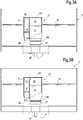
- a descaling device 21 which comprises a descaling-chemicals reservoir 23 having a top portion 23T and a bottom portion 23B.
- the bottom portion 23B of the descaling-chemicals reservoir 23 comprises an outlet port 25.
- the outlet port 25 can be provided with a closing valve 27 having a shutter 27S biased by an elastic member, e.g. a spring 27B, against a closure seat 27C. Under the elastic action of the spring 27B the shutter 27S closes the outlet port 25 when the descaling device 21 is not connected to the water tank 3 and/or to the hydraulic circuit 5 of the coffee machine 1.
- the descaling device 21 In use the descaling device 21 is introduced in the water tank 3 and attached to the bottom of the water tank 3.
- the descaling-chemicals reservoir 23 is thus fluidly coupled to the hydraulic circuit 5 of the beverage producing machine 1 through the outlet port 25.
- the valve 27 When the descaling device 21 is connected to the water tank 3, as shown in Fig. 4 , the valve 27 will open placing the descaling-chemicals reservoir in fluid communication with the hydraulic circuit 5 of the coffee machine 1, as will be disclosed in greater detail here below.
- the descaling device further comprises a water inlet port 29.
- the water inlet port 29 is arranged between the top portion and the bottom portion of the descaling-chemicals reservoir and preferably adjacent the bottom portion thereof, i.e. nearer to the bottom portion 23B than to the top portion 23T.
- a flow passage 31 extends from the water inlet port 29 towards the top portion 23T of the descaling-chemicals reservoir.
- the embodiments illustrated in Figs. 3A-4 the flow passage 31 is separated from the very descaling-chemicals reservoir 23 by a rupturable or removable partition wall 33. In this manner, descaling chemicals C contained in the descaling-chemicals reservoir will be preserved inside the descaling-chemicals reservoir 23 and will be prevented from exiting such reservoir on the one side by the partition wall 33 and on the other side by the valve 27.
- the partition wall 33 is ruptured so that a flow path is established between the flow passage 31 and the descaling-chemicals reservoir 23.
- connection of the descaling device 21 to the water tank 3 will also cause the valve 27 to open so that a communication will be established between the water inlet port 29 and the hydraulic circuit 5 of the coffee machine through the outlet port 25 when the water tank 3 is connected to said hydraulic circuit.
- FIG. 4 an enlargement of the bottom portion 23B of the descaling-chemicals reservoir 23 is shown in a cross section and in a condition where the descaling device 21 is connected with the water tank 3 and the latter is connected to the coffee machine 1.
- the water tank 3 is provided with a bottom connection 41, forming a water outlet passage through which water and descaling chemicals can flow into the hydraulic circuit 5 of the coffee machine 1.
- a valve 43 comprised of a stopper or shutter 45 biased by a spring 47 is arranged in the bottom connection 41 of the water tank 3.
- an upwardly projecting duct 49 extends from a bottom 51B of a seat 51 of the coffee machine wherein the water tank 3 is introduced. The upwardly projecting duct 49 co-acts with the shutter 45 of valve 43 when the water tank 3 is place in the seat 51 of the coffee machine 1. This causes the shutter 45 to lift against the elastic force of the spring 47, thus opening the valve 43 and establishing a connection between the water tank 3 and the hydraulic circuit 5 of the coffee machine 1 which is in fluid communication with the duct 49.
- the bottom connection 41 of water tank 3 also forms a seat 53 where the descaling device 21 can be connected, such that the descaling-chemicals reservoir becomes attached with the bottom portion 23B thereof to the bottom connection.
- the outlet port 25 of the descaling-chemicals reservoir 23 can thus be placed in fluid communication through the bottom of the water tank 3 with the hydraulic circuit of the beverage producing machine.
- the bottom portion 23B of the descaling-chemicals reservoir 23 comprises a collar 55 projecting from the descaling device 21 and forming the bottom portion 23B of the descaling-chemicals reservoir 23, said collar 55 being received into seat 53 so as to provide a fluid connection between the descaling-chemicals reservoir 23 and the bottom connection 41 of the water tank 3 and therethrough with the hydraulic circuit 5 of the beverage producing machine 1.
- a fixed pusher 57 arranged in the water outlet passage formed by the bottom connection 41 of the water tank 3 co-acts with the shutter 27S of the valve 27, lifting the stopper 27 as against the biasing force of the spring 27B, thus lifting the stopper 27S from the seat 27C of valve 27, so that the interior of the descaling-chemicals reservoir 23 will be placed in fluid communication, through the water outlet passage formed by the bottom connection 41, with the duct 49 and there through with the hydraulic circuit 5 of the coffee machine 1.
- the descaling cycle can start, once the rupturable partition wall 33 has been ruptured or opened, so as to establish a flow connection between the water inlet port 29 and the outlet port 25 of the descaling device 21.
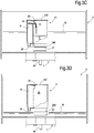
- Fig. 3B the partition wall 23 has been ruptured. This can occur, for example, by providing a flexible top portion 23T, which can be deformed by pushing from above in correspondence of the rupturable wall 33 until the latter breaks.
- the partition wall 33 can be designed also in other ways, provided it can be opened, ruptured or broken before starting the descaling cycle.
- the partition wall 33 can be entirely or partly movable from the exterior of the descaling device 21, for instance providing a sliding portion of the partition wall 33 which can be operated through a tongue or any other operating member which can be activated by the user from the exterior of the descaling device.
- the descaling chemicals will be gradually sucked from the bottom of the descaling-chemicals reservoir 23 and the level of the descaling chemicals C will lower (see Fig. 3C ).
- the pressure reduction caused by sucking the descaling chemicals from the descaling-chemicals reservoir 23 causes the water level in the flow passage 31 to raise until water starts flowing through the aperture formed by breaking or removing the partition wall 33, as shown in Fig. 3C .
- the concentration of the descaling chemicals in the flow pumped by the pump 9 through the hydraulic circuit 5 will continuously reduce until the descaling chemicals have been entirely removed from the descaling-chemicals reservoir 23. From this point onwards, only water will flow through the water passage 31, the descaling-chemicals reservoir 23 and finally through the water outlet 41 of the water tank 3 and the hydraulic circuit 5. The cycle will continue until the water level in the water tank 3 reaches the water inlet port 29 as shown in Fig. 3D . At this point the pump 9 will stop.
- the chemical composition of the liquid flowing through the hydraulic circuit 5 changes from undiluted descaling chemicals at the beginning of the cycle to pure water at the end of the cycle. Since the amount of water contained in the water tank 3 is considerably larger than the amount of the liquid descaling chemicals contained in the descaling device 21, at the end of the cycle, when the water level in the water tank 3 has reached the water inlet port 29, the entire hydraulic circuit 5 will be cleaned and any residues of descaling chemicals will be removed.
- the outlet port 25 of the descaling-chemicals reservoir 23 can be closed by a rupturable sealing or closing member, such as a membrane or film, rather than by a valve 27 with a stopper 27S, thus making the device 21 simpler and less expensive.
- a rupturable sealing or closing member such as a membrane or film
- a closure member in the form of a pierceable or rupturable membrane 61 is provided for closing the outlet port 25 of the descaling-chemicals reservoir 23.
- the water tank 3 can be provided with a piercer 63 which pierces or breaks the membrane 61 when the descaling device 21 is fitted into the seat 53 at the bottom of the water tank 3.
- the descaling device 21 can be a disposable unit usable only once.
- the descaling-chemicals reservoir 23 will be filled with liquid descaling chemicals at the time of manufacturing and the reservoir 23 will be sealed for instance by means of the membrane 61 or any other rupturable or removable closure member, or by a valve 27. After used, the descaling device 21 can be disposed of.
- the descaling device 21 can be designed for repeated use, by refilling the descaling 21 with a suitable amount of liquid descaling chemicals each time.
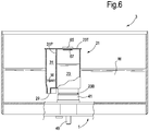
- Fig. 6 schematically illustrates, similarly to Figs. 3A-3D , a modified embodiment of the descaling device 21, which in this embodiment is designed for repeated use.
- the partition wall 33 can be omitted and the flow path 31 can be always in flow communication with the interior of the descaling-chemicals reservoir 23.
- the bottom of the descaling-chemicals reservoir 23 is closed by a valve 27 similarly to what has been described in connection with Fig. 4 .
- the top portion 23T of the descaling-chemicals reservoir 23 is provided with a removable air-tight closing stopper 65, which can sealingly close an aperture 67 provided in the top portion 23T of the descaling-chemicals reservoir 23.
- the descaling device 21 is as follows.
- the user fits the empty descaling device 21 with the bottom portion 23B of the descaling-chemicals reservoir 23 inside the seat 53 provided in the bottom of the water tank 3.
- the descaling-chemicals reservoir 23 is subsequently filled with a required amount of descaling chemicals through aperture 67 by removing the air-tight closing stopper 65.
- the required amount of liquid descaling chemicals can be filled in before fitting the descaling device 21 in the seat 53.
- the amount of liquid descaling chemicals filled in the descaling-chemicals reservoir 23 is such that the level of the descaling chemicals will be lower than a communication port 31P between the flow passage 31 and the descaling-chemicals reservoir 23.
- the 65 is put in place and air-tightly closed.
- the water tank 3 can be connected to the coffee machine 1, either before or after having connected the descaling device 21 to the water tank 3 and can be filled with the desired amount of fresh water.
- the descaling and washing cycle will end up once the descaling chemicals have been entirely sucked out from the descaling-chemicals reservoir 23 and the water from the water tank 3 has been removed, until the water level in the water tank 3 has reached the water inlet port 29.
- the embodiments of the descaling devices described so far provide for a descaling-chemicals reservoir which can be connected with the hydraulic circuit of the hot-beverage producing machine and with the interior of a water tank, wherein the device is arranged.
- Water is sucked from the external water tank through the water inlet port into and through the descaling-chemicals reservoir due to the pressure drop generated in the descaling-chemicals reservoir caused by suction of the descaling-chemicals from the descaling-chemicals reservoir in and through the hydraulic circuit.
- the pressure drop in the descaling-chemicals reservoir causes the water level to lift along the flow passage until the water fills the flow passage and starts flowing through the descaling-chemicals reservoir.
- the hydraulic circuit is thus first subject to a flow of descaling chemicals and subsequently to a flow of gradually thinner descaling-chemicals and water mixture. Since the volume of water in the water tank is comparably larger than the volume of descaling chemicals, the concentration of descaling chemicals will gradually decrease until only water will flow through the descaling-chemicals reservoir and the hydraulic circuit of the hot-beverage producing machine 1. At the end of the descaling process, when the water tank 3 is empty, the hydraulic circuit will be clean, i.e. free of descaling chemicals.
Claims (10)
- Verfahren zum Entkalken eines Hydraulikkreislaufs (5) einer Heißgetränke-Zubereitungsmaschine (1), wobei der Hydraulikkreislauf mindestens eine Pumpe (9) und einen Wassererhitzer (11) umfasst; wobei das Verfahren die folgenden Schritte umfasst:- Bereitstellen einer Entkalkungsvorrichtung (21), die einen Entkalkungschemikalienbehälter (23) zum Aufnehmen von flüssigen Entkalkungschemikalien darin umfasst und eine Wassereinlassöffnung (29) und eine Auslassöffnung (25) aufweist;- Bereitstellen eines Wassertanks (3) zum Aufnehmen von Wasser (W) darin und bereitgestellt mit einem unteren Anschluss (41), der einen Auslasskanal zum Abgeben von Wasser aus dem Wassertank (3) an den Hydraulikkreislauf (5) bildet;- Anordnen der Entkalkungsvorrichtung im Inneren des Wassertanks (3), Anschließen der Entkalkungsvorrichtung (21) an den unteren Anschluss (41) des Wassertanks (3) und Koppeln des Wassertanks (3) mit dem Hydraulikkreislauf (5), wodurch eine Strömungsverbindung zwischen dem Entkalkungschemikalienbehälter (23) und dem Hydraulikkreislauf (5) hergestellt wird;- Bereitstellen von Wasser im Wassertank (3);- Saugen von flüssigen Entkalkungschemikalien aus dem Entkalkungschemikalienbehälter (23) durch dessen Auslassöffnung (25), wodurch flüssige Entkalkungschemikalien durch den Hydraulikkreislauf (5) zirkulieren, während ein Druck in dem Entkalkungschemikalienbehälter (23) reduziert wird;- sequentielles Saugen von Wasser aus dem Wassertank (3) über einen Strömungspfad (29, 31), der den Wassertank (3) an den Entkalkungschemikalienbehälter (23) anschließt, und durch den Entkalkungschemikalienbehälter (23), wodurch Wasser durch den Hydraulikkreislauf (5) zirkuliert.
- Heißgetränke-Zubereitungsmaschine (1), umfassend:einen Wassertank (3);einen Hydraulikkreislauf (5), der aus einem Wassererhitzer (11), einer Pumpe (9) und einem Anschluss des Hydraulikkreislaufs an den Wassertank (3) besteht;und eine Entkalkungsvorrichtung zum Entkalken eines Hydraulikkreislaufs (5) einer Heißgetränke-Zubereitungsmaschine (1), wobei die Entkalkungsvorrichtung umfasst:- einen Entkalkungschemikalienbehälter (23), der bereitgestellt ist mit: einem oberen Abschnitt (23T); einem unteren Abschnitt (23B), der zum Koppeln mit einem unteren Anschluss (41) eines Wassertanks (3) konfiguriert ist; eine Auslassöffnung (25), die am oder nahe dem unteren Abschnitt (23B) angeordnet ist und ein öffenbares Verschlussglied (27; 61) zum Herstellen einer Strömungsverbindung des Entkalkungschemikalienbehälters (23) mit dem Hydraulikkreislauf (5) der Heißgetränke-Zubereitungsmaschine (1) aufweist;- eine Wassereinlassöffnung (29);- einen Wasserströmungskanal (31) zur Strömungsverbindung zwischen der Wassereinlassöffnung (29) und dem Entkalkungschemikalienbehälter (23);
wobei die Wassereinlassöffnung (29) und die Auslassöffnung (25) in Fluidverbindung gebracht werden können, so dass Wasser durch die Wassereinlassöffnung (29) gesaugt werden kann, veranlasst wird, durch den Entkalkungschemikalienbehälter (23) zu strömen und durch die Auslassöffnung (25) abgegeben zu werden, dadurch gekennzeichnet, dass die Entkalkungsvorrichtung (21) im Gebrauch innerhalb des Wassertanks (3) angeordnet werden kann und dass der Wassertank (3) einen unteren Anschluss (41) aufweist, der einen Wasserauslasskanal bildet, wobei der untere Anschluss (41) konfiguriert und angeordnet ist, um den Entkalkungschemikalienbehälter (23) mit dem Wasserauslasskanal zu verbinden und eine Strömungsverbindung zwischen dem Entkalkungschemikalienbehälter (23) und dem Hydraulikkreislauf (5) der Heißgetränke-Zubereitungsmaschine (1) herzustellen. - Heißgetränke-Zubereitungsmaschine nach Anspruch 2, wobei der Entkalkungschemikalienbehälter (23), die Auslassöffnung (25) und die Wassereinlassöffnung (29) so konfiguriert und angeordnet sind, dass mindestens ein Teil der im Entkalkungschemikalienbehälter (23) enthaltenen flüssigen Entkalkungschemikalien aus dem Entkalkungschemikalienbehälter (23) abgesaugt werden, der einen Druckabfall darin erzeugt, bevor Wasser in und durch den Entkalkungschemikalienbehälter (23) fließt.
- Heißgetränke-Zubereitungsmaschine nach Anspruch 2 oder 3, wobei die Wassereinlassöffnung (29) zwischen dem oberen Abschnitt (23T) und dem unteren Abschnitt (23B) des Entkalkungschemikalienbehälters (23) angeordnet ist; und wobei sich der Wasserströmungskanal (31) von der Wassereinlassöffnung (29) in Richtung des oberen Abschnitts (23T) des Entkalkungschemikalienbehälters (23) erstreckt, so dass das Saugen von Entkalkungschemikalien durch die Auslassöffnung (25) einen Druckabfall im Entkalkungschemikalienbehälter und ein daraus folgendes Saugen von Wasser durch die Wassereinlassöffnung (29), den Wasserströmungskanal (31) und den Entkalkungschemikalienbehälter (23) bewirkt.
- Heißgetränke-Zubereitungsmaschine nach Anspruch 2 oder 3 oder 4, wobei die Wassereinlassöffnung (29) neben dem unteren Abschnitt (23B) des Entkalkungschemikalienbehälters (23) angeordnet ist.
- Heißgetränke-Zubereitungsmaschine nach einem der Ansprüche 2 bis 5, wobei das Verschlussglied ein Element mit Sollbruchstelle (61) umfasst, das zum Öffnen der Auslassöffnung (25) zerbrochen werden kann.
- Heißgetränke-Zubereitungsmaschine nach einem der Ansprüche 2 bis 6, wobei das Verschlussglied ein Verschlussventil (27) mit einem Verschluss (27S) umfasst, wobei das Verschlussventil (27) nach Anschluss des Entkalkungschemikalienbehälters (23) an einen Hydraulikkreislauf (5) einer Getränke-Zubereitungsmaschine (1) oder an einen Wassertank (3) öffenbar ist.
- Heißgetränke-Zubereitungsmaschine nach einem der Ansprüche 2 bis 7, weiter umfassend eine Befüllungsöffnung (67) zum Befüllen des Entkalkungschemikalienbehälters (23) mit flüssigen Entkalkungschemikalien, und wobei die Befüllungsöffnung mit einem luftdichten Verschlussstopfen (65) versehen ist.
- Heißgetränke-Zubereitungsmaschine nach einem der Ansprüche 2 bis 8, wobei ein öffenbares Trennglied (33) zwischen der Wassereinlassöffnung (29) und dem Entkalkungschemikalienbehälter (23) angeordnet ist, wobei das Trennglied (33) vor Beginn eines Entkalkungszyklus mittels der Entkalkungsvorrichtung (21) geöffnet wird.
- Heißgetränke-Zubereitungsmaschine (1) nach einem der Ansprüche 2 bis 8, wobei ein Schließventil (45) an dem unteren Anschluss (41) angeordnet ist, und wobei das Schließventil (45) angeordnet und konfiguriert ist, um sich beim Anschluss des Wassertanks (3) an den Hydraulikkreislauf(5) der Heißgetränke-Zubereitungsmaschine (1) zu öffnen.
Priority Applications (2)
| Application Number | Priority Date | Filing Date | Title |
|---|---|---|---|
| PL14789807T PL3060089T3 (pl) | 2013-10-22 | 2014-10-22 | Odkamienianie maszyn do produkcji gorących napojów |
| EP14789807.6A EP3060089B1 (de) | 2013-10-22 | 2014-10-22 | Entfernung von ablagerungen aus heissgetränkautomaten |
Applications Claiming Priority (3)
| Application Number | Priority Date | Filing Date | Title |
|---|---|---|---|
| EP13189718 | 2013-10-22 | ||
| PCT/EP2014/072691 WO2015059213A1 (en) | 2013-10-22 | 2014-10-22 | Descaling hot-beverage producing machines |
| EP14789807.6A EP3060089B1 (de) | 2013-10-22 | 2014-10-22 | Entfernung von ablagerungen aus heissgetränkautomaten |
Publications (2)
| Publication Number | Publication Date |
|---|---|
| EP3060089A1 EP3060089A1 (de) | 2016-08-31 |
| EP3060089B1 true EP3060089B1 (de) | 2019-06-26 |
Family
ID=49484131
Family Applications (1)
| Application Number | Title | Priority Date | Filing Date |
|---|---|---|---|
| EP14789807.6A Active EP3060089B1 (de) | 2013-10-22 | 2014-10-22 | Entfernung von ablagerungen aus heissgetränkautomaten |
Country Status (8)
| Country | Link |
|---|---|
| US (1) | US10806295B2 (de) |
| EP (1) | EP3060089B1 (de) |
| CN (1) | CN105636489B (de) |
| AU (1) | AU2014338948B2 (de) |
| ES (1) | ES2745280T3 (de) |
| PL (1) | PL3060089T3 (de) |
| RU (1) | RU2674276C2 (de) |
| WO (1) | WO2015059213A1 (de) |
Families Citing this family (14)
| Publication number | Priority date | Publication date | Assignee | Title |
|---|---|---|---|---|
| WO2015059213A1 (en) * | 2013-10-22 | 2015-04-30 | Koninklijke Philips N.V. | Descaling hot-beverage producing machines |
| US10544306B2 (en) * | 2014-05-20 | 2020-01-28 | Whitford Corporation | Sol-gel compositions with improved hardness and impact resistance |
| DE102015108438A1 (de) * | 2015-05-28 | 2016-12-01 | Bwt Ag | Vorrichtung zur Reinigung von Automaten für die Herstellung von Heißgetränken, damit ausgerüsteter Automat sowie Verfahren zu dessen Reinigung |
| DE202015104155U1 (de) * | 2015-08-07 | 2015-11-04 | Franke Kaffeemaschinen Ag | Reinigungsmittelbehälter |
| DE102016124681A1 (de) * | 2016-12-16 | 2018-06-21 | Franke Kaffeemaschinen Ag | Getränkevollautomat für frischgebrühte Heißgetränke |
| DE102017102956A1 (de) * | 2017-02-14 | 2018-08-16 | Franke Water Systems Ag | Vorrichtung zur Ausgabe von Heißwasser |
| CN108784381B (zh) * | 2017-04-26 | 2020-10-27 | 九阳股份有限公司 | 一种豆浆机的自动清洗方法 |
| DE102017118598A1 (de) * | 2017-08-15 | 2019-02-21 | Franke Kaffeemaschinen Ag | VORRICHTUNG ZUM ZUBEREITEN VON HEIßGETRÄNKEN |
| CN107550288A (zh) * | 2017-09-20 | 2018-01-09 | 镇江巨商智能科技有限公司 | 一种设有循环清理机构的开水机 |
| US11202530B2 (en) * | 2019-05-10 | 2021-12-21 | B/E Aerospace, Inc. | Descaling module |
| WO2022073612A1 (fr) * | 2020-10-08 | 2022-04-14 | The Swatch Group Research And Development Ltd | Dispositif de dosage pour une machine de fabrication de preparation liquide |
| CN115183022A (zh) * | 2021-04-06 | 2022-10-14 | 恒洁卫浴集团有限公司 | 阻垢除垢模块、阻垢除垢淋浴设备及阻垢除垢淋浴龙头 |
| BE1030170B1 (de) * | 2022-01-10 | 2023-08-10 | Miele & Cie | Filtereinheit, Wasserführender Automat mit einer derartigen Filtereinheit, Verfahren zur Erkennung des Gebrauchszustandes einer Filtereinheit und Verfahren zur Bestimmung der Lebensdauer einer Filtereinheit |
| CN115026077A (zh) * | 2022-06-28 | 2022-09-09 | 朱孟仪 | 液体分配管路就地清洗系统及饮料配置辅助设备 |
Family Cites Families (17)
| Publication number | Priority date | Publication date | Assignee | Title |
|---|---|---|---|---|
| DE3133593A1 (de) | 1981-08-25 | 1983-04-07 | Harri 4000 Düsseldorf Thürer | Kaffeemaschine mit vollautomatischer entkalkung und aehnlich elektrisch betriebenen wasseraufbereitungsgeraeten. |
| US6889603B2 (en) * | 2002-12-24 | 2005-05-10 | Nestec S.A. | Clean-in-place automated food or beverage dispenser |
| EP1801516A1 (de) | 2005-12-23 | 2007-06-27 | Rhea Vendors S.p.A. | Verfahren und Vorrichtung gegen Kesselsteinablagerung in Wassererhitzer einer Getränkeausgabevorrichtung |
| DE102006023449A1 (de) | 2006-05-18 | 2007-11-22 | BSH Bosch und Siemens Hausgeräte GmbH | Verfahren und Vorrichtung zur Durchführung von Servicevorgängen in einer Heißgetränkezubereitungsvorrichtung |
| ITFI20070187A1 (it) | 2007-08-10 | 2009-02-11 | Saeco Ipr Ltd | "macchina per la produzione di bevande, in particolare caffe', con sistemi anticalcare e relativo metodo" |
| FR2929090B1 (fr) | 2008-03-26 | 2010-04-02 | Seb Sa | Machine pour la preparation de boissons comprenant un systeme de nettoyage d'une buse vapeur |
| CN101980641B (zh) * | 2008-04-07 | 2013-09-11 | 雀巢产品技术援助有限公司 | 带有内联式除垢系统的饮料制备设备和使用这种系统的除垢方法 |
| CN201371716Y (zh) * | 2009-03-18 | 2009-12-30 | 李安杰 | 一种过滤气压淋水器用容水罐 |
| CH703374B1 (de) | 2010-06-24 | 2015-01-30 | Eversys Ag | Reinigungssystem für einen Getränkeautomaten, vorzugsweise eine Kaffeemaschine. |
| EP2460449A1 (de) | 2010-12-06 | 2012-06-06 | Nestec S.A. | Getränkeherstellungsmaschine mit automatischem Reinigungssystem |
| KR101429537B1 (ko) * | 2011-07-11 | 2014-08-12 | 엘지디스플레이 주식회사 | 유기발광소자 |
| DE102011054601A1 (de) * | 2011-10-19 | 2013-04-25 | Eugster/Frismag Ag Elektrohaushaltgeräte | Kaffeemaschine, insbesondere Kaffeevollautomat sowie Verfahren zum Betreiben einer Kaffeemaschine |
| DE102011055264A1 (de) * | 2011-11-11 | 2013-05-16 | Miele & Cie. Kg | Vorrichtung zur Zubereitung und Ausgabe von Getränken |
| DE102012104860A1 (de) | 2012-06-05 | 2013-12-05 | Miele & Cie. Kg | Entkalkungsvorrichtung, Getränkeautomat mit einer derartigen Entkalkungsvorrichtung sowie Verfahren zur Anwendung einer Entkalkungsvorrichtung in einem Getränkeautomat |
| CN202932765U (zh) | 2012-07-19 | 2013-05-15 | 康奈尔有限公司 | 用于饮料用具的清洗系统 |
| CN203106791U (zh) | 2012-12-13 | 2013-08-07 | 苏州工业园区咖乐美电器有限公司 | 一种具有除钙功能的咖啡机 |
| WO2015059213A1 (en) * | 2013-10-22 | 2015-04-30 | Koninklijke Philips N.V. | Descaling hot-beverage producing machines |
-
2014
- 2014-10-22 WO PCT/EP2014/072691 patent/WO2015059213A1/en active Application Filing
- 2014-10-22 AU AU2014338948A patent/AU2014338948B2/en active Active
- 2014-10-22 EP EP14789807.6A patent/EP3060089B1/de active Active
- 2014-10-22 RU RU2016119787A patent/RU2674276C2/ru active
- 2014-10-22 US US15/028,462 patent/US10806295B2/en active Active
- 2014-10-22 CN CN201480058328.7A patent/CN105636489B/zh active Active
- 2014-10-22 PL PL14789807T patent/PL3060089T3/pl unknown
- 2014-10-22 ES ES14789807T patent/ES2745280T3/es active Active
Non-Patent Citations (1)
| Title |
|---|
| None * |
Also Published As
| Publication number | Publication date |
|---|---|
| EP3060089A1 (de) | 2016-08-31 |
| RU2674276C2 (ru) | 2018-12-06 |
| CN105636489A (zh) | 2016-06-01 |
| AU2014338948B2 (en) | 2019-01-17 |
| US10806295B2 (en) | 2020-10-20 |
| AU2014338948A1 (en) | 2016-06-09 |
| ES2745280T3 (es) | 2020-02-28 |
| RU2016119787A3 (de) | 2018-06-19 |
| PL3060089T3 (pl) | 2019-12-31 |
| RU2016119787A (ru) | 2017-11-28 |
| US20160249767A1 (en) | 2016-09-01 |
| CN105636489B (zh) | 2019-05-17 |
| WO2015059213A1 (en) | 2015-04-30 |
Similar Documents
| Publication | Publication Date | Title |
|---|---|---|
| EP3060089B1 (de) | Entfernung von ablagerungen aus heissgetränkautomaten | |
| JP6093383B2 (ja) | 洗浄可能な淹出ヘッドを有する飲料調製マシン | |
| CA2939167C (en) | Method for cleaning and/or disinfecting a milk-carrying system of a coffee machine and coffee machine | |
| JP5480283B2 (ja) | コーヒー機械 | |
| DK2363051T3 (en) | Coffee machine and method for the cleaning thereof. | |
| RU2438551C1 (ru) | Устройство для приготовления напитков и способ очистки устройства для приготовления напитков | |
| TWI439243B (zh) | 飲料形成機的排流 | |
| CN100493428C (zh) | 包括冲泡室和减压部件的饮料制作装置 | |
| US8763516B2 (en) | Device for feeding milk | |
| CA2990268A1 (en) | Cleaning module for a milk system and method thereof | |
| WO2015055460A1 (en) | Automatic machine for preparing beverages, such as espresso coffee, cappuccino and the like | |
| CN108064139A (zh) | 用于制备饮料具体是浓缩咖啡的机器以及其中使用的阀和阀单元 | |
| US20160183717A1 (en) | Improved apparatus for the preparation of one or a plurality of beverages | |
| JP2019122653A (ja) | ミルクフォーマ | |
| EP3072427A1 (de) | Heisse getränke zubereitender getränkespender | |
| KR20230098249A (ko) | 음료 추출 기기 및 그 관로 시스템과 작동 방법 | |
| IT202100008759A1 (it) | Sistema di pulizia dei condotti latte per una macchina per la preparazione di bevande | |
| AU2014336457A1 (en) | Automatic machine for preparing beverages, such as espresso coffee, cappuccino and the like |
Legal Events
| Date | Code | Title | Description |
|---|---|---|---|
| PUAI | Public reference made under article 153(3) epc to a published international application that has entered the european phase |
Free format text: ORIGINAL CODE: 0009012 |
|
| 17P | Request for examination filed |
Effective date: 20160523 |
|
| AK | Designated contracting states |
Kind code of ref document: A1 Designated state(s): AL AT BE BG CH CY CZ DE DK EE ES FI FR GB GR HR HU IE IS IT LI LT LU LV MC MK MT NL NO PL PT RO RS SE SI SK SM TR |
|
| AX | Request for extension of the european patent |
Extension state: BA ME |
|
| DAX | Request for extension of the european patent (deleted) | ||
| GRAP | Despatch of communication of intention to grant a patent |
Free format text: ORIGINAL CODE: EPIDOSNIGR1 |
|
| STAA | Information on the status of an ep patent application or granted ep patent |
Free format text: STATUS: GRANT OF PATENT IS INTENDED |
|
| INTG | Intention to grant announced |
Effective date: 20180822 |
|
| GRAJ | Information related to disapproval of communication of intention to grant by the applicant or resumption of examination proceedings by the epo deleted |
Free format text: ORIGINAL CODE: EPIDOSDIGR1 |
|
| STAA | Information on the status of an ep patent application or granted ep patent |
Free format text: STATUS: REQUEST FOR EXAMINATION WAS MADE |
|
| INTC | Intention to grant announced (deleted) | ||
| GRAP | Despatch of communication of intention to grant a patent |
Free format text: ORIGINAL CODE: EPIDOSNIGR1 |
|
| STAA | Information on the status of an ep patent application or granted ep patent |
Free format text: STATUS: GRANT OF PATENT IS INTENDED |
|
| INTG | Intention to grant announced |
Effective date: 20190118 |
|
| GRAS | Grant fee paid |
Free format text: ORIGINAL CODE: EPIDOSNIGR3 |
|
| GRAA | (expected) grant |
Free format text: ORIGINAL CODE: 0009210 |
|
| STAA | Information on the status of an ep patent application or granted ep patent |
Free format text: STATUS: THE PATENT HAS BEEN GRANTED |
|
| AK | Designated contracting states |
Kind code of ref document: B1 Designated state(s): AL AT BE BG CH CY CZ DE DK EE ES FI FR GB GR HR HU IE IS IT LI LT LU LV MC MK MT NL NO PL PT RO RS SE SI SK SM TR |
|
| REG | Reference to a national code |
Ref country code: GB Ref legal event code: FG4D |
|
| REG | Reference to a national code |
Ref country code: CH Ref legal event code: EP |
|
| REG | Reference to a national code |
Ref country code: AT Ref legal event code: REF Ref document number: 1147317 Country of ref document: AT Kind code of ref document: T Effective date: 20190715 |
|
| REG | Reference to a national code |
Ref country code: DE Ref legal event code: R096 Ref document number: 602014049139 Country of ref document: DE |
|
| REG | Reference to a national code |
Ref country code: IE Ref legal event code: FG4D |
|
| REG | Reference to a national code |
Ref country code: NL Ref legal event code: FP |
|
| PG25 | Lapsed in a contracting state [announced via postgrant information from national office to epo] |
Ref country code: SE Free format text: LAPSE BECAUSE OF FAILURE TO SUBMIT A TRANSLATION OF THE DESCRIPTION OR TO PAY THE FEE WITHIN THE PRESCRIBED TIME-LIMIT Effective date: 20190626 Ref country code: NO Free format text: LAPSE BECAUSE OF FAILURE TO SUBMIT A TRANSLATION OF THE DESCRIPTION OR TO PAY THE FEE WITHIN THE PRESCRIBED TIME-LIMIT Effective date: 20190926 Ref country code: LT Free format text: LAPSE BECAUSE OF FAILURE TO SUBMIT A TRANSLATION OF THE DESCRIPTION OR TO PAY THE FEE WITHIN THE PRESCRIBED TIME-LIMIT Effective date: 20190626 Ref country code: HR Free format text: LAPSE BECAUSE OF FAILURE TO SUBMIT A TRANSLATION OF THE DESCRIPTION OR TO PAY THE FEE WITHIN THE PRESCRIBED TIME-LIMIT Effective date: 20190626 Ref country code: AL Free format text: LAPSE BECAUSE OF FAILURE TO SUBMIT A TRANSLATION OF THE DESCRIPTION OR TO PAY THE FEE WITHIN THE PRESCRIBED TIME-LIMIT Effective date: 20190626 Ref country code: FI Free format text: LAPSE BECAUSE OF FAILURE TO SUBMIT A TRANSLATION OF THE DESCRIPTION OR TO PAY THE FEE WITHIN THE PRESCRIBED TIME-LIMIT Effective date: 20190626 |
|
| REG | Reference to a national code |
Ref country code: LT Ref legal event code: MG4D |
|
| PG25 | Lapsed in a contracting state [announced via postgrant information from national office to epo] |
Ref country code: GR Free format text: LAPSE BECAUSE OF FAILURE TO SUBMIT A TRANSLATION OF THE DESCRIPTION OR TO PAY THE FEE WITHIN THE PRESCRIBED TIME-LIMIT Effective date: 20190927 Ref country code: BG Free format text: LAPSE BECAUSE OF FAILURE TO SUBMIT A TRANSLATION OF THE DESCRIPTION OR TO PAY THE FEE WITHIN THE PRESCRIBED TIME-LIMIT Effective date: 20190926 Ref country code: RS Free format text: LAPSE BECAUSE OF FAILURE TO SUBMIT A TRANSLATION OF THE DESCRIPTION OR TO PAY THE FEE WITHIN THE PRESCRIBED TIME-LIMIT Effective date: 20190626 Ref country code: LV Free format text: LAPSE BECAUSE OF FAILURE TO SUBMIT A TRANSLATION OF THE DESCRIPTION OR TO PAY THE FEE WITHIN THE PRESCRIBED TIME-LIMIT Effective date: 20190626 |
|
| REG | Reference to a national code |
Ref country code: AT Ref legal event code: MK05 Ref document number: 1147317 Country of ref document: AT Kind code of ref document: T Effective date: 20190626 |
|
| PG25 | Lapsed in a contracting state [announced via postgrant information from national office to epo] |
Ref country code: EE Free format text: LAPSE BECAUSE OF FAILURE TO SUBMIT A TRANSLATION OF THE DESCRIPTION OR TO PAY THE FEE WITHIN THE PRESCRIBED TIME-LIMIT Effective date: 20190626 Ref country code: AT Free format text: LAPSE BECAUSE OF FAILURE TO SUBMIT A TRANSLATION OF THE DESCRIPTION OR TO PAY THE FEE WITHIN THE PRESCRIBED TIME-LIMIT Effective date: 20190626 Ref country code: PT Free format text: LAPSE BECAUSE OF FAILURE TO SUBMIT A TRANSLATION OF THE DESCRIPTION OR TO PAY THE FEE WITHIN THE PRESCRIBED TIME-LIMIT Effective date: 20191028 Ref country code: SK Free format text: LAPSE BECAUSE OF FAILURE TO SUBMIT A TRANSLATION OF THE DESCRIPTION OR TO PAY THE FEE WITHIN THE PRESCRIBED TIME-LIMIT Effective date: 20190626 Ref country code: CZ Free format text: LAPSE BECAUSE OF FAILURE TO SUBMIT A TRANSLATION OF THE DESCRIPTION OR TO PAY THE FEE WITHIN THE PRESCRIBED TIME-LIMIT Effective date: 20190626 Ref country code: RO Free format text: LAPSE BECAUSE OF FAILURE TO SUBMIT A TRANSLATION OF THE DESCRIPTION OR TO PAY THE FEE WITHIN THE PRESCRIBED TIME-LIMIT Effective date: 20190626 |
|
| PG25 | Lapsed in a contracting state [announced via postgrant information from national office to epo] |
Ref country code: IS Free format text: LAPSE BECAUSE OF FAILURE TO SUBMIT A TRANSLATION OF THE DESCRIPTION OR TO PAY THE FEE WITHIN THE PRESCRIBED TIME-LIMIT Effective date: 20191026 Ref country code: SM Free format text: LAPSE BECAUSE OF FAILURE TO SUBMIT A TRANSLATION OF THE DESCRIPTION OR TO PAY THE FEE WITHIN THE PRESCRIBED TIME-LIMIT Effective date: 20190626 Ref country code: IT Free format text: LAPSE BECAUSE OF FAILURE TO SUBMIT A TRANSLATION OF THE DESCRIPTION OR TO PAY THE FEE WITHIN THE PRESCRIBED TIME-LIMIT Effective date: 20190626 |
|
| REG | Reference to a national code |
Ref country code: ES Ref legal event code: FG2A Ref document number: 2745280 Country of ref document: ES Kind code of ref document: T3 Effective date: 20200228 |
|
| RAP2 | Party data changed (patent owner data changed or rights of a patent transferred) |
Owner name: KONINKLIJKE PHILIPS N.V. |
|
| PG25 | Lapsed in a contracting state [announced via postgrant information from national office to epo] |
Ref country code: TR Free format text: LAPSE BECAUSE OF FAILURE TO SUBMIT A TRANSLATION OF THE DESCRIPTION OR TO PAY THE FEE WITHIN THE PRESCRIBED TIME-LIMIT Effective date: 20190626 |
|
| PG25 | Lapsed in a contracting state [announced via postgrant information from national office to epo] |
Ref country code: DK Free format text: LAPSE BECAUSE OF FAILURE TO SUBMIT A TRANSLATION OF THE DESCRIPTION OR TO PAY THE FEE WITHIN THE PRESCRIBED TIME-LIMIT Effective date: 20190626 |
|
| PG25 | Lapsed in a contracting state [announced via postgrant information from national office to epo] |
Ref country code: IS Free format text: LAPSE BECAUSE OF FAILURE TO SUBMIT A TRANSLATION OF THE DESCRIPTION OR TO PAY THE FEE WITHIN THE PRESCRIBED TIME-LIMIT Effective date: 20200224 Ref country code: MC Free format text: LAPSE BECAUSE OF FAILURE TO SUBMIT A TRANSLATION OF THE DESCRIPTION OR TO PAY THE FEE WITHIN THE PRESCRIBED TIME-LIMIT Effective date: 20190626 |
|
| REG | Reference to a national code |
Ref country code: CH Ref legal event code: PL |
|
| REG | Reference to a national code |
Ref country code: DE Ref legal event code: R097 Ref document number: 602014049139 Country of ref document: DE |
|
| PLBE | No opposition filed within time limit |
Free format text: ORIGINAL CODE: 0009261 |
|
| STAA | Information on the status of an ep patent application or granted ep patent |
Free format text: STATUS: NO OPPOSITION FILED WITHIN TIME LIMIT |
|
| PG2D | Information on lapse in contracting state deleted |
Ref country code: IS |
|
| PG25 | Lapsed in a contracting state [announced via postgrant information from national office to epo] |
Ref country code: LU Free format text: LAPSE BECAUSE OF NON-PAYMENT OF DUE FEES Effective date: 20191022 Ref country code: CH Free format text: LAPSE BECAUSE OF NON-PAYMENT OF DUE FEES Effective date: 20191031 Ref country code: LI Free format text: LAPSE BECAUSE OF NON-PAYMENT OF DUE FEES Effective date: 20191031 |
|
| 26N | No opposition filed |
Effective date: 20200603 |
|
| REG | Reference to a national code |
Ref country code: BE Ref legal event code: MM Effective date: 20191031 |
|
| PG25 | Lapsed in a contracting state [announced via postgrant information from national office to epo] |
Ref country code: BE Free format text: LAPSE BECAUSE OF NON-PAYMENT OF DUE FEES Effective date: 20191031 Ref country code: SI Free format text: LAPSE BECAUSE OF FAILURE TO SUBMIT A TRANSLATION OF THE DESCRIPTION OR TO PAY THE FEE WITHIN THE PRESCRIBED TIME-LIMIT Effective date: 20190626 |
|
| GBPC | Gb: european patent ceased through non-payment of renewal fee |
Effective date: 20191022 |
|
| PG25 | Lapsed in a contracting state [announced via postgrant information from national office to epo] |
Ref country code: IE Free format text: LAPSE BECAUSE OF NON-PAYMENT OF DUE FEES Effective date: 20191022 Ref country code: GB Free format text: LAPSE BECAUSE OF NON-PAYMENT OF DUE FEES Effective date: 20191022 |
|
| PG25 | Lapsed in a contracting state [announced via postgrant information from national office to epo] |
Ref country code: CY Free format text: LAPSE BECAUSE OF FAILURE TO SUBMIT A TRANSLATION OF THE DESCRIPTION OR TO PAY THE FEE WITHIN THE PRESCRIBED TIME-LIMIT Effective date: 20190626 |
|
| PG25 | Lapsed in a contracting state [announced via postgrant information from national office to epo] |
Ref country code: HU Free format text: LAPSE BECAUSE OF FAILURE TO SUBMIT A TRANSLATION OF THE DESCRIPTION OR TO PAY THE FEE WITHIN THE PRESCRIBED TIME-LIMIT; INVALID AB INITIO Effective date: 20141022 Ref country code: MT Free format text: LAPSE BECAUSE OF FAILURE TO SUBMIT A TRANSLATION OF THE DESCRIPTION OR TO PAY THE FEE WITHIN THE PRESCRIBED TIME-LIMIT Effective date: 20190626 |
|
| PG25 | Lapsed in a contracting state [announced via postgrant information from national office to epo] |
Ref country code: MK Free format text: LAPSE BECAUSE OF FAILURE TO SUBMIT A TRANSLATION OF THE DESCRIPTION OR TO PAY THE FEE WITHIN THE PRESCRIBED TIME-LIMIT Effective date: 20190626 |
|
| P01 | Opt-out of the competence of the unified patent court (upc) registered |
Effective date: 20230530 |
|
| REG | Reference to a national code |
Ref country code: NL Ref legal event code: PD Owner name: VERSUNI HOLDING B.V.; NL Free format text: DETAILS ASSIGNMENT: CHANGE OF OWNER(S), ASSIGNMENT; FORMER OWNER NAME: KONINKLIJKE PHILIPS N.V. Effective date: 20231108 |
|
| PGFP | Annual fee paid to national office [announced via postgrant information from national office to epo] |
Ref country code: NL Payment date: 20231026 Year of fee payment: 10 |
|
| REG | Reference to a national code |
Ref country code: DE Ref legal event code: R081 Ref document number: 602014049139 Country of ref document: DE Owner name: VERSUNI HOLDING B.V., NL Free format text: FORMER OWNER: KONINKLIJKE PHILIPS N.V., EINDHOVEN, NL |
|
| PGFP | Annual fee paid to national office [announced via postgrant information from national office to epo] |
Ref country code: ES Payment date: 20231110 Year of fee payment: 10 |
|
| PGFP | Annual fee paid to national office [announced via postgrant information from national office to epo] |
Ref country code: FR Payment date: 20231026 Year of fee payment: 10 Ref country code: DE Payment date: 20231027 Year of fee payment: 10 |
|
| PGFP | Annual fee paid to national office [announced via postgrant information from national office to epo] |
Ref country code: PL Payment date: 20231011 Year of fee payment: 10 |