EP3059536A1 - Verfahren und Vorrichtung zur Gewinnung eines Druckstickstoffprodukts - Google Patents
Verfahren und Vorrichtung zur Gewinnung eines Druckstickstoffprodukts Download PDFInfo
- Publication number
- EP3059536A1 EP3059536A1 EP15000484.4A EP15000484A EP3059536A1 EP 3059536 A1 EP3059536 A1 EP 3059536A1 EP 15000484 A EP15000484 A EP 15000484A EP 3059536 A1 EP3059536 A1 EP 3059536A1
- Authority
- EP
- European Patent Office
- Prior art keywords
- pressure column
- low
- residual gas
- heat exchanger
- condenser
- Prior art date
- Legal status (The legal status is an assumption and is not a legal conclusion. Google has not performed a legal analysis and makes no representation as to the accuracy of the status listed.)
- Withdrawn
Links
- IJGRMHOSHXDMSA-UHFFFAOYSA-N Atomic nitrogen Chemical compound N#N IJGRMHOSHXDMSA-UHFFFAOYSA-N 0.000 title claims abstract description 117
- 229910052757 nitrogen Inorganic materials 0.000 title claims abstract description 57
- 238000000034 method Methods 0.000 title claims abstract description 21
- 239000007789 gas Substances 0.000 claims abstract description 58
- 238000001704 evaporation Methods 0.000 claims abstract description 12
- 230000008020 evaporation Effects 0.000 claims abstract description 11
- 239000007788 liquid Substances 0.000 claims abstract description 9
- 238000004821 distillation Methods 0.000 claims abstract description 5
- 238000000926 separation method Methods 0.000 claims abstract description 4
- 239000012530 fluid Substances 0.000 claims description 5
- 238000010438 heat treatment Methods 0.000 claims description 3
- 239000003990 capacitor Substances 0.000 claims description 2
- 238000001816 cooling Methods 0.000 claims description 2
- 238000011144 upstream manufacturing Methods 0.000 claims description 2
- 230000005540 biological transmission Effects 0.000 description 2
- 230000006835 compression Effects 0.000 description 2
- 238000007906 compression Methods 0.000 description 2
- 238000005265 energy consumption Methods 0.000 description 2
- 238000012986 modification Methods 0.000 description 2
- 230000004048 modification Effects 0.000 description 2
- 238000011084 recovery Methods 0.000 description 2
- 241000883306 Huso huso Species 0.000 description 1
- 230000003321 amplification Effects 0.000 description 1
- QVGXLLKOCUKJST-UHFFFAOYSA-N atomic oxygen Chemical compound [O] QVGXLLKOCUKJST-UHFFFAOYSA-N 0.000 description 1
- 238000003889 chemical engineering Methods 0.000 description 1
- 238000004140 cleaning Methods 0.000 description 1
- 238000009833 condensation Methods 0.000 description 1
- 230000005494 condensation Effects 0.000 description 1
- 238000010276 construction Methods 0.000 description 1
- 238000000354 decomposition reaction Methods 0.000 description 1
- 230000000694 effects Effects 0.000 description 1
- 239000011552 falling film Substances 0.000 description 1
- 230000002349 favourable effect Effects 0.000 description 1
- 238000007667 floating Methods 0.000 description 1
- 238000004519 manufacturing process Methods 0.000 description 1
- QGZKDVFQNNGYKY-NJFSPNSNSA-N nitrogen-16 Chemical compound [16NH3] QGZKDVFQNNGYKY-NJFSPNSNSA-N 0.000 description 1
- 238000003199 nucleic acid amplification method Methods 0.000 description 1
- 239000001301 oxygen Substances 0.000 description 1
- 229910052760 oxygen Inorganic materials 0.000 description 1
- 238000010926 purge Methods 0.000 description 1
- 238000005057 refrigeration Methods 0.000 description 1
- 238000001228 spectrum Methods 0.000 description 1
- 125000005931 tert-butyloxycarbonyl group Chemical group [H]C([H])([H])C(OC(*)=O)(C([H])([H])[H])C([H])([H])[H] 0.000 description 1
- 230000008016 vaporization Effects 0.000 description 1
Images


Classifications
-
- F—MECHANICAL ENGINEERING; LIGHTING; HEATING; WEAPONS; BLASTING
- F25—REFRIGERATION OR COOLING; COMBINED HEATING AND REFRIGERATION SYSTEMS; HEAT PUMP SYSTEMS; MANUFACTURE OR STORAGE OF ICE; LIQUEFACTION SOLIDIFICATION OF GASES
- F25J—LIQUEFACTION, SOLIDIFICATION OR SEPARATION OF GASES OR GASEOUS OR LIQUEFIED GASEOUS MIXTURES BY PRESSURE AND COLD TREATMENT OR BY BRINGING THEM INTO THE SUPERCRITICAL STATE
- F25J3/00—Processes or apparatus for separating the constituents of gaseous or liquefied gaseous mixtures involving the use of liquefaction or solidification
- F25J3/02—Processes or apparatus for separating the constituents of gaseous or liquefied gaseous mixtures involving the use of liquefaction or solidification by rectification, i.e. by continuous interchange of heat and material between a vapour stream and a liquid stream
- F25J3/04—Processes or apparatus for separating the constituents of gaseous or liquefied gaseous mixtures involving the use of liquefaction or solidification by rectification, i.e. by continuous interchange of heat and material between a vapour stream and a liquid stream for air
- F25J3/04763—Start-up or control of the process; Details of the apparatus used
- F25J3/04769—Operation, control and regulation of the process; Instrumentation within the process
- F25J3/04854—Safety aspects of operation
- F25J3/0486—Safety aspects of operation of vaporisers for oxygen enriched liquids, e.g. purging of liquids
-
- F—MECHANICAL ENGINEERING; LIGHTING; HEATING; WEAPONS; BLASTING
- F25—REFRIGERATION OR COOLING; COMBINED HEATING AND REFRIGERATION SYSTEMS; HEAT PUMP SYSTEMS; MANUFACTURE OR STORAGE OF ICE; LIQUEFACTION SOLIDIFICATION OF GASES
- F25J—LIQUEFACTION, SOLIDIFICATION OR SEPARATION OF GASES OR GASEOUS OR LIQUEFIED GASEOUS MIXTURES BY PRESSURE AND COLD TREATMENT OR BY BRINGING THEM INTO THE SUPERCRITICAL STATE
- F25J3/00—Processes or apparatus for separating the constituents of gaseous or liquefied gaseous mixtures involving the use of liquefaction or solidification
- F25J3/02—Processes or apparatus for separating the constituents of gaseous or liquefied gaseous mixtures involving the use of liquefaction or solidification by rectification, i.e. by continuous interchange of heat and material between a vapour stream and a liquid stream
- F25J3/04—Processes or apparatus for separating the constituents of gaseous or liquefied gaseous mixtures involving the use of liquefaction or solidification by rectification, i.e. by continuous interchange of heat and material between a vapour stream and a liquid stream for air
- F25J3/04006—Providing pressurised feed air or process streams within or from the air fractionation unit
- F25J3/04048—Providing pressurised feed air or process streams within or from the air fractionation unit by compression of cold gaseous streams, e.g. intermediate or oxygen enriched (waste) streams
- F25J3/04054—Providing pressurised feed air or process streams within or from the air fractionation unit by compression of cold gaseous streams, e.g. intermediate or oxygen enriched (waste) streams of air
-
- F—MECHANICAL ENGINEERING; LIGHTING; HEATING; WEAPONS; BLASTING
- F25—REFRIGERATION OR COOLING; COMBINED HEATING AND REFRIGERATION SYSTEMS; HEAT PUMP SYSTEMS; MANUFACTURE OR STORAGE OF ICE; LIQUEFACTION SOLIDIFICATION OF GASES
- F25J—LIQUEFACTION, SOLIDIFICATION OR SEPARATION OF GASES OR GASEOUS OR LIQUEFIED GASEOUS MIXTURES BY PRESSURE AND COLD TREATMENT OR BY BRINGING THEM INTO THE SUPERCRITICAL STATE
- F25J3/00—Processes or apparatus for separating the constituents of gaseous or liquefied gaseous mixtures involving the use of liquefaction or solidification
- F25J3/02—Processes or apparatus for separating the constituents of gaseous or liquefied gaseous mixtures involving the use of liquefaction or solidification by rectification, i.e. by continuous interchange of heat and material between a vapour stream and a liquid stream
- F25J3/04—Processes or apparatus for separating the constituents of gaseous or liquefied gaseous mixtures involving the use of liquefaction or solidification by rectification, i.e. by continuous interchange of heat and material between a vapour stream and a liquid stream for air
- F25J3/04006—Providing pressurised feed air or process streams within or from the air fractionation unit
- F25J3/04012—Providing pressurised feed air or process streams within or from the air fractionation unit by compression of warm gaseous streams; details of intake or interstage cooling
- F25J3/04018—Providing pressurised feed air or process streams within or from the air fractionation unit by compression of warm gaseous streams; details of intake or interstage cooling of main feed air
-
- F—MECHANICAL ENGINEERING; LIGHTING; HEATING; WEAPONS; BLASTING
- F25—REFRIGERATION OR COOLING; COMBINED HEATING AND REFRIGERATION SYSTEMS; HEAT PUMP SYSTEMS; MANUFACTURE OR STORAGE OF ICE; LIQUEFACTION SOLIDIFICATION OF GASES
- F25J—LIQUEFACTION, SOLIDIFICATION OR SEPARATION OF GASES OR GASEOUS OR LIQUEFIED GASEOUS MIXTURES BY PRESSURE AND COLD TREATMENT OR BY BRINGING THEM INTO THE SUPERCRITICAL STATE
- F25J3/00—Processes or apparatus for separating the constituents of gaseous or liquefied gaseous mixtures involving the use of liquefaction or solidification
- F25J3/02—Processes or apparatus for separating the constituents of gaseous or liquefied gaseous mixtures involving the use of liquefaction or solidification by rectification, i.e. by continuous interchange of heat and material between a vapour stream and a liquid stream
- F25J3/04—Processes or apparatus for separating the constituents of gaseous or liquefied gaseous mixtures involving the use of liquefaction or solidification by rectification, i.e. by continuous interchange of heat and material between a vapour stream and a liquid stream for air
- F25J3/04006—Providing pressurised feed air or process streams within or from the air fractionation unit
- F25J3/04012—Providing pressurised feed air or process streams within or from the air fractionation unit by compression of warm gaseous streams; details of intake or interstage cooling
- F25J3/0403—Providing pressurised feed air or process streams within or from the air fractionation unit by compression of warm gaseous streams; details of intake or interstage cooling of nitrogen
-
- F—MECHANICAL ENGINEERING; LIGHTING; HEATING; WEAPONS; BLASTING
- F25—REFRIGERATION OR COOLING; COMBINED HEATING AND REFRIGERATION SYSTEMS; HEAT PUMP SYSTEMS; MANUFACTURE OR STORAGE OF ICE; LIQUEFACTION SOLIDIFICATION OF GASES
- F25J—LIQUEFACTION, SOLIDIFICATION OR SEPARATION OF GASES OR GASEOUS OR LIQUEFIED GASEOUS MIXTURES BY PRESSURE AND COLD TREATMENT OR BY BRINGING THEM INTO THE SUPERCRITICAL STATE
- F25J3/00—Processes or apparatus for separating the constituents of gaseous or liquefied gaseous mixtures involving the use of liquefaction or solidification
- F25J3/02—Processes or apparatus for separating the constituents of gaseous or liquefied gaseous mixtures involving the use of liquefaction or solidification by rectification, i.e. by continuous interchange of heat and material between a vapour stream and a liquid stream
- F25J3/04—Processes or apparatus for separating the constituents of gaseous or liquefied gaseous mixtures involving the use of liquefaction or solidification by rectification, i.e. by continuous interchange of heat and material between a vapour stream and a liquid stream for air
- F25J3/04006—Providing pressurised feed air or process streams within or from the air fractionation unit
- F25J3/04048—Providing pressurised feed air or process streams within or from the air fractionation unit by compression of cold gaseous streams, e.g. intermediate or oxygen enriched (waste) streams
- F25J3/0406—Providing pressurised feed air or process streams within or from the air fractionation unit by compression of cold gaseous streams, e.g. intermediate or oxygen enriched (waste) streams of nitrogen
-
- F—MECHANICAL ENGINEERING; LIGHTING; HEATING; WEAPONS; BLASTING
- F25—REFRIGERATION OR COOLING; COMBINED HEATING AND REFRIGERATION SYSTEMS; HEAT PUMP SYSTEMS; MANUFACTURE OR STORAGE OF ICE; LIQUEFACTION SOLIDIFICATION OF GASES
- F25J—LIQUEFACTION, SOLIDIFICATION OR SEPARATION OF GASES OR GASEOUS OR LIQUEFIED GASEOUS MIXTURES BY PRESSURE AND COLD TREATMENT OR BY BRINGING THEM INTO THE SUPERCRITICAL STATE
- F25J3/00—Processes or apparatus for separating the constituents of gaseous or liquefied gaseous mixtures involving the use of liquefaction or solidification
- F25J3/02—Processes or apparatus for separating the constituents of gaseous or liquefied gaseous mixtures involving the use of liquefaction or solidification by rectification, i.e. by continuous interchange of heat and material between a vapour stream and a liquid stream
- F25J3/04—Processes or apparatus for separating the constituents of gaseous or liquefied gaseous mixtures involving the use of liquefaction or solidification by rectification, i.e. by continuous interchange of heat and material between a vapour stream and a liquid stream for air
- F25J3/04006—Providing pressurised feed air or process streams within or from the air fractionation unit
- F25J3/04078—Providing pressurised feed air or process streams within or from the air fractionation unit providing pressurized products by liquid compression and vaporisation with cold recovery, i.e. so-called internal compression
- F25J3/04084—Providing pressurised feed air or process streams within or from the air fractionation unit providing pressurized products by liquid compression and vaporisation with cold recovery, i.e. so-called internal compression of nitrogen
-
- F—MECHANICAL ENGINEERING; LIGHTING; HEATING; WEAPONS; BLASTING
- F25—REFRIGERATION OR COOLING; COMBINED HEATING AND REFRIGERATION SYSTEMS; HEAT PUMP SYSTEMS; MANUFACTURE OR STORAGE OF ICE; LIQUEFACTION SOLIDIFICATION OF GASES
- F25J—LIQUEFACTION, SOLIDIFICATION OR SEPARATION OF GASES OR GASEOUS OR LIQUEFIED GASEOUS MIXTURES BY PRESSURE AND COLD TREATMENT OR BY BRINGING THEM INTO THE SUPERCRITICAL STATE
- F25J3/00—Processes or apparatus for separating the constituents of gaseous or liquefied gaseous mixtures involving the use of liquefaction or solidification
- F25J3/02—Processes or apparatus for separating the constituents of gaseous or liquefied gaseous mixtures involving the use of liquefaction or solidification by rectification, i.e. by continuous interchange of heat and material between a vapour stream and a liquid stream
- F25J3/04—Processes or apparatus for separating the constituents of gaseous or liquefied gaseous mixtures involving the use of liquefaction or solidification by rectification, i.e. by continuous interchange of heat and material between a vapour stream and a liquid stream for air
- F25J3/04006—Providing pressurised feed air or process streams within or from the air fractionation unit
- F25J3/04109—Arrangements of compressors and /or their drivers
- F25J3/04115—Arrangements of compressors and /or their drivers characterised by the type of prime driver, e.g. hot gas expander
- F25J3/04121—Steam turbine as the prime mechanical driver
-
- F—MECHANICAL ENGINEERING; LIGHTING; HEATING; WEAPONS; BLASTING
- F25—REFRIGERATION OR COOLING; COMBINED HEATING AND REFRIGERATION SYSTEMS; HEAT PUMP SYSTEMS; MANUFACTURE OR STORAGE OF ICE; LIQUEFACTION SOLIDIFICATION OF GASES
- F25J—LIQUEFACTION, SOLIDIFICATION OR SEPARATION OF GASES OR GASEOUS OR LIQUEFIED GASEOUS MIXTURES BY PRESSURE AND COLD TREATMENT OR BY BRINGING THEM INTO THE SUPERCRITICAL STATE
- F25J3/00—Processes or apparatus for separating the constituents of gaseous or liquefied gaseous mixtures involving the use of liquefaction or solidification
- F25J3/02—Processes or apparatus for separating the constituents of gaseous or liquefied gaseous mixtures involving the use of liquefaction or solidification by rectification, i.e. by continuous interchange of heat and material between a vapour stream and a liquid stream
- F25J3/04—Processes or apparatus for separating the constituents of gaseous or liquefied gaseous mixtures involving the use of liquefaction or solidification by rectification, i.e. by continuous interchange of heat and material between a vapour stream and a liquid stream for air
- F25J3/04006—Providing pressurised feed air or process streams within or from the air fractionation unit
- F25J3/04109—Arrangements of compressors and /or their drivers
- F25J3/04115—Arrangements of compressors and /or their drivers characterised by the type of prime driver, e.g. hot gas expander
- F25J3/04133—Electrical motor as the prime mechanical driver
-
- F—MECHANICAL ENGINEERING; LIGHTING; HEATING; WEAPONS; BLASTING
- F25—REFRIGERATION OR COOLING; COMBINED HEATING AND REFRIGERATION SYSTEMS; HEAT PUMP SYSTEMS; MANUFACTURE OR STORAGE OF ICE; LIQUEFACTION SOLIDIFICATION OF GASES
- F25J—LIQUEFACTION, SOLIDIFICATION OR SEPARATION OF GASES OR GASEOUS OR LIQUEFIED GASEOUS MIXTURES BY PRESSURE AND COLD TREATMENT OR BY BRINGING THEM INTO THE SUPERCRITICAL STATE
- F25J3/00—Processes or apparatus for separating the constituents of gaseous or liquefied gaseous mixtures involving the use of liquefaction or solidification
- F25J3/02—Processes or apparatus for separating the constituents of gaseous or liquefied gaseous mixtures involving the use of liquefaction or solidification by rectification, i.e. by continuous interchange of heat and material between a vapour stream and a liquid stream
- F25J3/04—Processes or apparatus for separating the constituents of gaseous or liquefied gaseous mixtures involving the use of liquefaction or solidification by rectification, i.e. by continuous interchange of heat and material between a vapour stream and a liquid stream for air
- F25J3/04006—Providing pressurised feed air or process streams within or from the air fractionation unit
- F25J3/04109—Arrangements of compressors and /or their drivers
- F25J3/04145—Mechanically coupling of different compressors of the air fractionation process to the same driver(s)
-
- F—MECHANICAL ENGINEERING; LIGHTING; HEATING; WEAPONS; BLASTING
- F25—REFRIGERATION OR COOLING; COMBINED HEATING AND REFRIGERATION SYSTEMS; HEAT PUMP SYSTEMS; MANUFACTURE OR STORAGE OF ICE; LIQUEFACTION SOLIDIFICATION OF GASES
- F25J—LIQUEFACTION, SOLIDIFICATION OR SEPARATION OF GASES OR GASEOUS OR LIQUEFIED GASEOUS MIXTURES BY PRESSURE AND COLD TREATMENT OR BY BRINGING THEM INTO THE SUPERCRITICAL STATE
- F25J3/00—Processes or apparatus for separating the constituents of gaseous or liquefied gaseous mixtures involving the use of liquefaction or solidification
- F25J3/02—Processes or apparatus for separating the constituents of gaseous or liquefied gaseous mixtures involving the use of liquefaction or solidification by rectification, i.e. by continuous interchange of heat and material between a vapour stream and a liquid stream
- F25J3/04—Processes or apparatus for separating the constituents of gaseous or liquefied gaseous mixtures involving the use of liquefaction or solidification by rectification, i.e. by continuous interchange of heat and material between a vapour stream and a liquid stream for air
- F25J3/04151—Purification and (pre-)cooling of the feed air; recuperative heat-exchange with product streams
- F25J3/04187—Cooling of the purified feed air by recuperative heat-exchange; Heat-exchange with product streams
-
- F—MECHANICAL ENGINEERING; LIGHTING; HEATING; WEAPONS; BLASTING
- F25—REFRIGERATION OR COOLING; COMBINED HEATING AND REFRIGERATION SYSTEMS; HEAT PUMP SYSTEMS; MANUFACTURE OR STORAGE OF ICE; LIQUEFACTION SOLIDIFICATION OF GASES
- F25J—LIQUEFACTION, SOLIDIFICATION OR SEPARATION OF GASES OR GASEOUS OR LIQUEFIED GASEOUS MIXTURES BY PRESSURE AND COLD TREATMENT OR BY BRINGING THEM INTO THE SUPERCRITICAL STATE
- F25J3/00—Processes or apparatus for separating the constituents of gaseous or liquefied gaseous mixtures involving the use of liquefaction or solidification
- F25J3/02—Processes or apparatus for separating the constituents of gaseous or liquefied gaseous mixtures involving the use of liquefaction or solidification by rectification, i.e. by continuous interchange of heat and material between a vapour stream and a liquid stream
- F25J3/04—Processes or apparatus for separating the constituents of gaseous or liquefied gaseous mixtures involving the use of liquefaction or solidification by rectification, i.e. by continuous interchange of heat and material between a vapour stream and a liquid stream for air
- F25J3/04248—Generation of cold for compensating heat leaks or liquid production, e.g. by Joule-Thompson expansion
- F25J3/04284—Generation of cold for compensating heat leaks or liquid production, e.g. by Joule-Thompson expansion using internal refrigeration by open-loop gas work expansion, e.g. of intermediate or oxygen enriched (waste-)streams
- F25J3/04321—Generation of cold for compensating heat leaks or liquid production, e.g. by Joule-Thompson expansion using internal refrigeration by open-loop gas work expansion, e.g. of intermediate or oxygen enriched (waste-)streams of oxygen
-
- F—MECHANICAL ENGINEERING; LIGHTING; HEATING; WEAPONS; BLASTING
- F25—REFRIGERATION OR COOLING; COMBINED HEATING AND REFRIGERATION SYSTEMS; HEAT PUMP SYSTEMS; MANUFACTURE OR STORAGE OF ICE; LIQUEFACTION SOLIDIFICATION OF GASES
- F25J—LIQUEFACTION, SOLIDIFICATION OR SEPARATION OF GASES OR GASEOUS OR LIQUEFIED GASEOUS MIXTURES BY PRESSURE AND COLD TREATMENT OR BY BRINGING THEM INTO THE SUPERCRITICAL STATE
- F25J3/00—Processes or apparatus for separating the constituents of gaseous or liquefied gaseous mixtures involving the use of liquefaction or solidification
- F25J3/02—Processes or apparatus for separating the constituents of gaseous or liquefied gaseous mixtures involving the use of liquefaction or solidification by rectification, i.e. by continuous interchange of heat and material between a vapour stream and a liquid stream
- F25J3/04—Processes or apparatus for separating the constituents of gaseous or liquefied gaseous mixtures involving the use of liquefaction or solidification by rectification, i.e. by continuous interchange of heat and material between a vapour stream and a liquid stream for air
- F25J3/04248—Generation of cold for compensating heat leaks or liquid production, e.g. by Joule-Thompson expansion
- F25J3/04375—Details relating to the work expansion, e.g. process parameter etc.
- F25J3/04393—Details relating to the work expansion, e.g. process parameter etc. using multiple or multistage gas work expansion
-
- F—MECHANICAL ENGINEERING; LIGHTING; HEATING; WEAPONS; BLASTING
- F25—REFRIGERATION OR COOLING; COMBINED HEATING AND REFRIGERATION SYSTEMS; HEAT PUMP SYSTEMS; MANUFACTURE OR STORAGE OF ICE; LIQUEFACTION SOLIDIFICATION OF GASES
- F25J—LIQUEFACTION, SOLIDIFICATION OR SEPARATION OF GASES OR GASEOUS OR LIQUEFIED GASEOUS MIXTURES BY PRESSURE AND COLD TREATMENT OR BY BRINGING THEM INTO THE SUPERCRITICAL STATE
- F25J3/00—Processes or apparatus for separating the constituents of gaseous or liquefied gaseous mixtures involving the use of liquefaction or solidification
- F25J3/02—Processes or apparatus for separating the constituents of gaseous or liquefied gaseous mixtures involving the use of liquefaction or solidification by rectification, i.e. by continuous interchange of heat and material between a vapour stream and a liquid stream
- F25J3/04—Processes or apparatus for separating the constituents of gaseous or liquefied gaseous mixtures involving the use of liquefaction or solidification by rectification, i.e. by continuous interchange of heat and material between a vapour stream and a liquid stream for air
- F25J3/04406—Processes or apparatus for separating the constituents of gaseous or liquefied gaseous mixtures involving the use of liquefaction or solidification by rectification, i.e. by continuous interchange of heat and material between a vapour stream and a liquid stream for air using a dual pressure main column system
- F25J3/04412—Processes or apparatus for separating the constituents of gaseous or liquefied gaseous mixtures involving the use of liquefaction or solidification by rectification, i.e. by continuous interchange of heat and material between a vapour stream and a liquid stream for air using a dual pressure main column system in a classical double column flowsheet, i.e. with thermal coupling by a main reboiler-condenser in the bottom of low pressure respectively top of high pressure column
-
- F—MECHANICAL ENGINEERING; LIGHTING; HEATING; WEAPONS; BLASTING
- F25—REFRIGERATION OR COOLING; COMBINED HEATING AND REFRIGERATION SYSTEMS; HEAT PUMP SYSTEMS; MANUFACTURE OR STORAGE OF ICE; LIQUEFACTION SOLIDIFICATION OF GASES
- F25J—LIQUEFACTION, SOLIDIFICATION OR SEPARATION OF GASES OR GASEOUS OR LIQUEFIED GASEOUS MIXTURES BY PRESSURE AND COLD TREATMENT OR BY BRINGING THEM INTO THE SUPERCRITICAL STATE
- F25J3/00—Processes or apparatus for separating the constituents of gaseous or liquefied gaseous mixtures involving the use of liquefaction or solidification
- F25J3/02—Processes or apparatus for separating the constituents of gaseous or liquefied gaseous mixtures involving the use of liquefaction or solidification by rectification, i.e. by continuous interchange of heat and material between a vapour stream and a liquid stream
- F25J3/04—Processes or apparatus for separating the constituents of gaseous or liquefied gaseous mixtures involving the use of liquefaction or solidification by rectification, i.e. by continuous interchange of heat and material between a vapour stream and a liquid stream for air
- F25J3/04521—Coupling of the air fractionation unit to an air gas-consuming unit, so-called integrated processes
- F25J3/04563—Integration with a nitrogen consuming unit, e.g. for purging, inerting, cooling or heating
- F25J3/04575—Integration with a nitrogen consuming unit, e.g. for purging, inerting, cooling or heating for a gas expansion plant, e.g. dilution of the combustion gas in a gas turbine
-
- F—MECHANICAL ENGINEERING; LIGHTING; HEATING; WEAPONS; BLASTING
- F25—REFRIGERATION OR COOLING; COMBINED HEATING AND REFRIGERATION SYSTEMS; HEAT PUMP SYSTEMS; MANUFACTURE OR STORAGE OF ICE; LIQUEFACTION SOLIDIFICATION OF GASES
- F25J—LIQUEFACTION, SOLIDIFICATION OR SEPARATION OF GASES OR GASEOUS OR LIQUEFIED GASEOUS MIXTURES BY PRESSURE AND COLD TREATMENT OR BY BRINGING THEM INTO THE SUPERCRITICAL STATE
- F25J3/00—Processes or apparatus for separating the constituents of gaseous or liquefied gaseous mixtures involving the use of liquefaction or solidification
- F25J3/02—Processes or apparatus for separating the constituents of gaseous or liquefied gaseous mixtures involving the use of liquefaction or solidification by rectification, i.e. by continuous interchange of heat and material between a vapour stream and a liquid stream
- F25J3/04—Processes or apparatus for separating the constituents of gaseous or liquefied gaseous mixtures involving the use of liquefaction or solidification by rectification, i.e. by continuous interchange of heat and material between a vapour stream and a liquid stream for air
- F25J3/04763—Start-up or control of the process; Details of the apparatus used
- F25J3/04769—Operation, control and regulation of the process; Instrumentation within the process
- F25J3/04854—Safety aspects of operation
-
- F—MECHANICAL ENGINEERING; LIGHTING; HEATING; WEAPONS; BLASTING
- F25—REFRIGERATION OR COOLING; COMBINED HEATING AND REFRIGERATION SYSTEMS; HEAT PUMP SYSTEMS; MANUFACTURE OR STORAGE OF ICE; LIQUEFACTION SOLIDIFICATION OF GASES
- F25J—LIQUEFACTION, SOLIDIFICATION OR SEPARATION OF GASES OR GASEOUS OR LIQUEFIED GASEOUS MIXTURES BY PRESSURE AND COLD TREATMENT OR BY BRINGING THEM INTO THE SUPERCRITICAL STATE
- F25J3/00—Processes or apparatus for separating the constituents of gaseous or liquefied gaseous mixtures involving the use of liquefaction or solidification
- F25J3/02—Processes or apparatus for separating the constituents of gaseous or liquefied gaseous mixtures involving the use of liquefaction or solidification by rectification, i.e. by continuous interchange of heat and material between a vapour stream and a liquid stream
- F25J3/04—Processes or apparatus for separating the constituents of gaseous or liquefied gaseous mixtures involving the use of liquefaction or solidification by rectification, i.e. by continuous interchange of heat and material between a vapour stream and a liquid stream for air
- F25J3/04763—Start-up or control of the process; Details of the apparatus used
- F25J3/04866—Construction and layout of air fractionation equipments, e.g. valves, machines
- F25J3/04872—Vertical layout of cold equipments within in the cold box, e.g. columns, heat exchangers etc.
- F25J3/04878—Side by side arrangement of multiple vessels in a main column system, wherein the vessels are normally mounted one upon the other or forming different sections of the same column
-
- F—MECHANICAL ENGINEERING; LIGHTING; HEATING; WEAPONS; BLASTING
- F25—REFRIGERATION OR COOLING; COMBINED HEATING AND REFRIGERATION SYSTEMS; HEAT PUMP SYSTEMS; MANUFACTURE OR STORAGE OF ICE; LIQUEFACTION SOLIDIFICATION OF GASES
- F25J—LIQUEFACTION, SOLIDIFICATION OR SEPARATION OF GASES OR GASEOUS OR LIQUEFIED GASEOUS MIXTURES BY PRESSURE AND COLD TREATMENT OR BY BRINGING THEM INTO THE SUPERCRITICAL STATE
- F25J3/00—Processes or apparatus for separating the constituents of gaseous or liquefied gaseous mixtures involving the use of liquefaction or solidification
- F25J3/02—Processes or apparatus for separating the constituents of gaseous or liquefied gaseous mixtures involving the use of liquefaction or solidification by rectification, i.e. by continuous interchange of heat and material between a vapour stream and a liquid stream
- F25J3/04—Processes or apparatus for separating the constituents of gaseous or liquefied gaseous mixtures involving the use of liquefaction or solidification by rectification, i.e. by continuous interchange of heat and material between a vapour stream and a liquid stream for air
- F25J3/04763—Start-up or control of the process; Details of the apparatus used
- F25J3/04866—Construction and layout of air fractionation equipments, e.g. valves, machines
- F25J3/04896—Details of columns, e.g. internals, inlet/outlet devices
- F25J3/04915—Combinations of different material exchange elements, e.g. within different columns
-
- F—MECHANICAL ENGINEERING; LIGHTING; HEATING; WEAPONS; BLASTING
- F25—REFRIGERATION OR COOLING; COMBINED HEATING AND REFRIGERATION SYSTEMS; HEAT PUMP SYSTEMS; MANUFACTURE OR STORAGE OF ICE; LIQUEFACTION SOLIDIFICATION OF GASES
- F25J—LIQUEFACTION, SOLIDIFICATION OR SEPARATION OF GASES OR GASEOUS OR LIQUEFIED GASEOUS MIXTURES BY PRESSURE AND COLD TREATMENT OR BY BRINGING THEM INTO THE SUPERCRITICAL STATE
- F25J3/00—Processes or apparatus for separating the constituents of gaseous or liquefied gaseous mixtures involving the use of liquefaction or solidification
- F25J3/02—Processes or apparatus for separating the constituents of gaseous or liquefied gaseous mixtures involving the use of liquefaction or solidification by rectification, i.e. by continuous interchange of heat and material between a vapour stream and a liquid stream
- F25J3/04—Processes or apparatus for separating the constituents of gaseous or liquefied gaseous mixtures involving the use of liquefaction or solidification by rectification, i.e. by continuous interchange of heat and material between a vapour stream and a liquid stream for air
- F25J3/04763—Start-up or control of the process; Details of the apparatus used
- F25J3/04866—Construction and layout of air fractionation equipments, e.g. valves, machines
- F25J3/04975—Construction and layout of air fractionation equipments, e.g. valves, machines adapted for special use of the air fractionation unit, e.g. transportable devices by truck or small scale use
- F25J3/04987—Construction and layout of air fractionation equipments, e.g. valves, machines adapted for special use of the air fractionation unit, e.g. transportable devices by truck or small scale use for offshore use
-
- F—MECHANICAL ENGINEERING; LIGHTING; HEATING; WEAPONS; BLASTING
- F25—REFRIGERATION OR COOLING; COMBINED HEATING AND REFRIGERATION SYSTEMS; HEAT PUMP SYSTEMS; MANUFACTURE OR STORAGE OF ICE; LIQUEFACTION SOLIDIFICATION OF GASES
- F25J—LIQUEFACTION, SOLIDIFICATION OR SEPARATION OF GASES OR GASEOUS OR LIQUEFIED GASEOUS MIXTURES BY PRESSURE AND COLD TREATMENT OR BY BRINGING THEM INTO THE SUPERCRITICAL STATE
- F25J2200/00—Processes or apparatus using separation by rectification
- F25J2200/20—Processes or apparatus using separation by rectification in an elevated pressure multiple column system wherein the lowest pressure column is at a pressure well above the minimum pressure needed to overcome pressure drop to reject the products to atmosphere
-
- F—MECHANICAL ENGINEERING; LIGHTING; HEATING; WEAPONS; BLASTING
- F25—REFRIGERATION OR COOLING; COMBINED HEATING AND REFRIGERATION SYSTEMS; HEAT PUMP SYSTEMS; MANUFACTURE OR STORAGE OF ICE; LIQUEFACTION SOLIDIFICATION OF GASES
- F25J—LIQUEFACTION, SOLIDIFICATION OR SEPARATION OF GASES OR GASEOUS OR LIQUEFIED GASEOUS MIXTURES BY PRESSURE AND COLD TREATMENT OR BY BRINGING THEM INTO THE SUPERCRITICAL STATE
- F25J2200/00—Processes or apparatus using separation by rectification
- F25J2200/50—Processes or apparatus using separation by rectification using multiple (re-)boiler-condensers at different heights of the column
- F25J2200/54—Processes or apparatus using separation by rectification using multiple (re-)boiler-condensers at different heights of the column in the low pressure column of a double pressure main column system
-
- F—MECHANICAL ENGINEERING; LIGHTING; HEATING; WEAPONS; BLASTING
- F25—REFRIGERATION OR COOLING; COMBINED HEATING AND REFRIGERATION SYSTEMS; HEAT PUMP SYSTEMS; MANUFACTURE OR STORAGE OF ICE; LIQUEFACTION SOLIDIFICATION OF GASES
- F25J—LIQUEFACTION, SOLIDIFICATION OR SEPARATION OF GASES OR GASEOUS OR LIQUEFIED GASEOUS MIXTURES BY PRESSURE AND COLD TREATMENT OR BY BRINGING THEM INTO THE SUPERCRITICAL STATE
- F25J2200/00—Processes or apparatus using separation by rectification
- F25J2200/90—Details relating to column internals, e.g. structured packing, gas or liquid distribution
- F25J2200/94—Details relating to the withdrawal point
-
- F—MECHANICAL ENGINEERING; LIGHTING; HEATING; WEAPONS; BLASTING
- F25—REFRIGERATION OR COOLING; COMBINED HEATING AND REFRIGERATION SYSTEMS; HEAT PUMP SYSTEMS; MANUFACTURE OR STORAGE OF ICE; LIQUEFACTION SOLIDIFICATION OF GASES
- F25J—LIQUEFACTION, SOLIDIFICATION OR SEPARATION OF GASES OR GASEOUS OR LIQUEFIED GASEOUS MIXTURES BY PRESSURE AND COLD TREATMENT OR BY BRINGING THEM INTO THE SUPERCRITICAL STATE
- F25J2235/00—Processes or apparatus involving steps for increasing the pressure or for conveying of liquid process streams
- F25J2235/42—Processes or apparatus involving steps for increasing the pressure or for conveying of liquid process streams the fluid being nitrogen
-
- F—MECHANICAL ENGINEERING; LIGHTING; HEATING; WEAPONS; BLASTING
- F25—REFRIGERATION OR COOLING; COMBINED HEATING AND REFRIGERATION SYSTEMS; HEAT PUMP SYSTEMS; MANUFACTURE OR STORAGE OF ICE; LIQUEFACTION SOLIDIFICATION OF GASES
- F25J—LIQUEFACTION, SOLIDIFICATION OR SEPARATION OF GASES OR GASEOUS OR LIQUEFIED GASEOUS MIXTURES BY PRESSURE AND COLD TREATMENT OR BY BRINGING THEM INTO THE SUPERCRITICAL STATE
- F25J2235/00—Processes or apparatus involving steps for increasing the pressure or for conveying of liquid process streams
- F25J2235/50—Processes or apparatus involving steps for increasing the pressure or for conveying of liquid process streams the fluid being oxygen
-
- F—MECHANICAL ENGINEERING; LIGHTING; HEATING; WEAPONS; BLASTING
- F25—REFRIGERATION OR COOLING; COMBINED HEATING AND REFRIGERATION SYSTEMS; HEAT PUMP SYSTEMS; MANUFACTURE OR STORAGE OF ICE; LIQUEFACTION SOLIDIFICATION OF GASES
- F25J—LIQUEFACTION, SOLIDIFICATION OR SEPARATION OF GASES OR GASEOUS OR LIQUEFIED GASEOUS MIXTURES BY PRESSURE AND COLD TREATMENT OR BY BRINGING THEM INTO THE SUPERCRITICAL STATE
- F25J2240/00—Processes or apparatus involving steps for expanding of process streams
- F25J2240/02—Expansion of a process fluid in a work-extracting turbine (i.e. isentropic expansion), e.g. of the feed stream
- F25J2240/04—Multiple expansion turbines in parallel
-
- F—MECHANICAL ENGINEERING; LIGHTING; HEATING; WEAPONS; BLASTING
- F25—REFRIGERATION OR COOLING; COMBINED HEATING AND REFRIGERATION SYSTEMS; HEAT PUMP SYSTEMS; MANUFACTURE OR STORAGE OF ICE; LIQUEFACTION SOLIDIFICATION OF GASES
- F25J—LIQUEFACTION, SOLIDIFICATION OR SEPARATION OF GASES OR GASEOUS OR LIQUEFIED GASEOUS MIXTURES BY PRESSURE AND COLD TREATMENT OR BY BRINGING THEM INTO THE SUPERCRITICAL STATE
- F25J2240/00—Processes or apparatus involving steps for expanding of process streams
- F25J2240/40—Expansion without extracting work, i.e. isenthalpic throttling, e.g. JT valve, regulating valve or venturi, or isentropic nozzle, e.g. Laval
- F25J2240/44—Expansion without extracting work, i.e. isenthalpic throttling, e.g. JT valve, regulating valve or venturi, or isentropic nozzle, e.g. Laval the fluid being nitrogen
-
- F—MECHANICAL ENGINEERING; LIGHTING; HEATING; WEAPONS; BLASTING
- F25—REFRIGERATION OR COOLING; COMBINED HEATING AND REFRIGERATION SYSTEMS; HEAT PUMP SYSTEMS; MANUFACTURE OR STORAGE OF ICE; LIQUEFACTION SOLIDIFICATION OF GASES
- F25J—LIQUEFACTION, SOLIDIFICATION OR SEPARATION OF GASES OR GASEOUS OR LIQUEFIED GASEOUS MIXTURES BY PRESSURE AND COLD TREATMENT OR BY BRINGING THEM INTO THE SUPERCRITICAL STATE
- F25J2245/00—Processes or apparatus involving steps for recycling of process streams
- F25J2245/42—Processes or apparatus involving steps for recycling of process streams the recycled stream being nitrogen
-
- F—MECHANICAL ENGINEERING; LIGHTING; HEATING; WEAPONS; BLASTING
- F25—REFRIGERATION OR COOLING; COMBINED HEATING AND REFRIGERATION SYSTEMS; HEAT PUMP SYSTEMS; MANUFACTURE OR STORAGE OF ICE; LIQUEFACTION SOLIDIFICATION OF GASES
- F25J—LIQUEFACTION, SOLIDIFICATION OR SEPARATION OF GASES OR GASEOUS OR LIQUEFIED GASEOUS MIXTURES BY PRESSURE AND COLD TREATMENT OR BY BRINGING THEM INTO THE SUPERCRITICAL STATE
- F25J2250/00—Details related to the use of reboiler-condensers
- F25J2250/02—Bath type boiler-condenser using thermo-siphon effect, e.g. with natural or forced circulation or pool boiling, i.e. core-in-kettle heat exchanger
-
- F—MECHANICAL ENGINEERING; LIGHTING; HEATING; WEAPONS; BLASTING
- F25—REFRIGERATION OR COOLING; COMBINED HEATING AND REFRIGERATION SYSTEMS; HEAT PUMP SYSTEMS; MANUFACTURE OR STORAGE OF ICE; LIQUEFACTION SOLIDIFICATION OF GASES
- F25J—LIQUEFACTION, SOLIDIFICATION OR SEPARATION OF GASES OR GASEOUS OR LIQUEFIED GASEOUS MIXTURES BY PRESSURE AND COLD TREATMENT OR BY BRINGING THEM INTO THE SUPERCRITICAL STATE
- F25J2250/00—Details related to the use of reboiler-condensers
- F25J2250/04—Down-flowing type boiler-condenser, i.e. with evaporation of a falling liquid film
-
- F—MECHANICAL ENGINEERING; LIGHTING; HEATING; WEAPONS; BLASTING
- F25—REFRIGERATION OR COOLING; COMBINED HEATING AND REFRIGERATION SYSTEMS; HEAT PUMP SYSTEMS; MANUFACTURE OR STORAGE OF ICE; LIQUEFACTION SOLIDIFICATION OF GASES
- F25J—LIQUEFACTION, SOLIDIFICATION OR SEPARATION OF GASES OR GASEOUS OR LIQUEFIED GASEOUS MIXTURES BY PRESSURE AND COLD TREATMENT OR BY BRINGING THEM INTO THE SUPERCRITICAL STATE
- F25J2290/00—Other details not covered by groups F25J2200/00 - F25J2280/00
- F25J2290/12—Particular process parameters like pressure, temperature, ratios
Definitions
- the invention relates to a method according to the preamble of patent claim 1.
- the main condenser and the low-pressure column top condenser are formed in the invention as a condenser-evaporator.
- the term "condenser-evaporator” refers to a heat exchanger in which a first condensing fluid stream undergoes indirect heat exchange with a second evaporating fluid stream.
- Each condenser-evaporator has a liquefaction space and an evaporation space, which consist of liquefaction passages or evaporation passages. In the liquefaction space, the condensation (liquefaction) of the first fluid flow is performed, in the evaporation space the evaporation of the second fluid flow. Evaporation and liquefaction space are formed by groups of passages that are in heat exchange relationship with each other.
- both capacitors can each be formed by a single heat exchanger block or by a plurality of heat exchanger blocks, which are arranged in a common pressure vessel. Both can be designed as single or multi-storey bath evaporator, forced flow evaporator or as falling film evaporator.
- a “main heat exchanger” serves to cool feed air in indirect heat exchange with recycle streams from the distillation column system. It may be formed from a single or multiple parallel and / or serially connected heat exchanger sections, for example one or more plate heat exchanger blocks.
- EP 2463232 A1 A method of the type mentioned is out EP 2463232 A1 known.
- the mechanical energy generated in the residual gas turbine is transferred to a cold compressor, which drives a boosting circuit that essentially corresponds to the Spectra process developed by the BOC Group ( EP 412793 A1 and EP 773417 A2 ).
- the invention has for its object to provide a method and a corresponding device, which have a lower energy consumption.
- the cold compressor is used here directly to compress nitrogen product, namely that of the low pressure column, which is brought to about high-pressure column pressure, for example. He is thus no longer available for the amplification cycle, the at EP 2463232 A1 contributes to increasing the yield and thus to reducing energy consumption.
- an additional third pressure nitrogen stream may be formed by another portion of the nitrogen product of the low pressure column by passing it directly into the main heat exchanger and delivering it as product under the low pressure column pressure (minus pressure drops).
- the first residual gas turbine and cold compressor are mechanically coupled. This can be accomplished via a common shaft or gear.
- the residual gas turbine may be mechanically coupled to a generator or an oil brake.
- the first residual gas turbine is mechanically coupled to an electric generator and the cold compressor is driven by an electric motor; the energy generated in the generator is then electrically transmitted to the engine, thereby driving the cold compressor.
- a second part of the warmed to the intermediate temperature residual gas in a second residual gas turbine is working expanded, which is connected in parallel to the first residual gas turbine, which is coupled to the cold compressor.
- the first residual gas turbine can then be coupled alone with the cold compressor, the second residual gas turbine with a generator or a dissipative brake.
- the first, second or both pressure nitrogen streams downstream of the main heat exchanger may be further compressed in a nitrogen compressor.
- both pressure nitrogen streams are brought together in the nitrogen compressor to a higher pressure.
- the nitrogen compressor is formed by the ni last stages of the combined n-stage compressor.
- an eight-stage compressor is used, whose three to four last stages are used as nitrogen compressor.
- the invention also relates to a device for recovering a compressed nitrogen product by cryogenic separation of air according to claim 10.
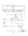
- Atmospheric air is sucked through a filter 1 from a main air compressor 2 and compressed to a pressure of about 15 bar.
- the compressed feed air 3 is cooled in a pre-cooler 4. This may include an aftercooler for indirect cooling or a direct contact radiator or both.
- the pre-cooled feed air 5 is cleaned in a cleaning device 6, which is usually formed by a pair of switchable adsorber.
- the compressed, precooled and purified feed air 7 is cooled in a main heat exchanger 8 to about dew point and introduced via line 9 into the high-pressure column 10.
- the high-pressure column 10 is part of the distillation column system, which also has a low-pressure column 11, a main condenser 12 and a low-pressure column top condenser 13.
- a first part 15 of the top gas 14 of the high-pressure column 10 is introduced into the liquefaction space of the main condenser 12 and condensed there at least partially.
- Liquid nitrogen 16 formed in the liquefaction space of the main condenser 12 is introduced into the high-pressure column 10 and serves there as a return to a first part.
- a second part 19 of the top gas 14 of the high-pressure column 10 is passed as the first pressurized nitrogen product stream 19 via line 20 to the main heat exchanger 8 and heated there to about ambient temperature.
- the warm pressure nitrogen 21 can - as in FIG. 1 shown in a nitrogen compressor 22 with aftercooler 23 are further increased in pressure, in principle to any desired discharge pressure. It is finally withdrawn as a pressurized nitrogen product (PGAN).
- the nitrogen compressor 22 and the aftercooler 23 may be omitted.
- the top gas 26 of the low-pressure column 11 is introduced into the liquefaction space of the low-pressure column top condenser 13.
- the liquid nitrogen 27 formed there is introduced into the low-pressure column 11.
- the bottom liquid 28 of the low-pressure column 11 is cooled in the UKG 18 and introduced via line 29 into the evaporation space of the low-pressure column top condenser 13, which is flushed via a purge line 39 continuously or intermittently.
- There formed gas is warmed up as residual gas 30 in the UKG 18.
- the residual gas 31 downstream of the UKGs 18 is fed to the main heat exchanger 8 at the cold end and there to a Intermediate temperature warmed up.
- the residual gas 32 under the intermediate temperature is supplied to a first residual gas turbine 33 and there relaxes work.
- the expanded residual gas 34 is reintroduced into the main heat exchanger 8 and warmed to the warm end.
- the warmed residual gas 35 leaves the system at about ambient temperature.
- the residual gas turbine 33 is mechanically coupled to a cold compressor 36 via a common shaft or gear.
- a nitrogen stream 37 is withdrawn in gaseous form from the top of the low pressure column 11, compressed in the cold compressor 36 to about high pressure column pressure and then mixed as the second pressure nitrogen product stream 38 with the first pressurized nitrogen product stream 19 and heated together with this in the main heat exchanger 8 and finally withdrawn as compressed nitrogen product (PGAN).
- GPN compressed nitrogen product
- the residual gas turbine 33 does not deliver its entire mechanical energy to the cold compressor 36, but also drives a generator 40, which sits on the same shaft or is connected to the same gear.
- a dissipative brake may also be used, for example an oil brake.
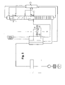
- FIG. 2 For example, two residual gas turbines 33, 233 connected in parallel are used, one of which is coupled to the cold compressor 36 and the other to a generator 240 (or a dissipative brake).
- a combined compressor 302 is used, which fulfills both tasks.
- the remaining ni 3 stages form the nitrogen product compressor. This allows a PGAN final pressure of about 70 to 100 bar can be achieved.
- the two pressurized nitrogen product streams 19, 38 are warmed in separate passage groups of the main heat exchanger 8.
- the warmed nitrogen streams 419 and 438 are combined at 420.
- the second pressurized nitrogen product stream 38 from the Cold compressor 36 can thus be introduced at a higher temperature into the main heat exchanger 8 than the first pressurized nitrogen product stream 19.
- the process can be made energetically somewhat cheaper.
- FIG. 5 the energy transfer between the first residual gas turbine 33 and cold compressor 36 in contrast to FIG. 1 not mechanically, but electrically made.
- the first residual gas turbine 33 is mechanically coupled to an electric generator 40.
- the electrical energy obtained there is at least partially transmitted via an electrical line network to a motor 540, which in turn is mechanically coupled to the cold compressor 36 and drives it.
- FIGS. 2 to 5 can also be combined with each other as desired, for example, to a system with two residual gas turbines and combined compressor and two passage groups in the main heat exchanger for the two pressure nitrogen streams.
- high-pressure column with sieve trays
- low-pressure column with packs or sieve trays
- the invention is also suitable for offshore concepts, such as floating oil recovery plants for oil or gas fields (enhanced oil recovery - EOR).
Abstract
Das Verfahren und die Vorrichtung dienen zur Gewinnung eines Druckstickstoffprodukts durch Tieftemperaturzerlegung von Luft in einem Destillationssäulen-System, das eine Hochdrucksäule (10) und eine Niederdrucksäule (11) sowie einen Hauptkondensator (12) und einen Niederdrucksäulen-Kopfkondensator (13) aufweist, die beide als Kondensator-Verdampfer ausgebildet sind. Sumpfflüssigkeit (28, 29) der Niederdrucksäule (11) wird in den Verdampfungsraum des Niederdrucksäulen-Kopfkondensators (13) eingeleitet. Dort gebildetes Gas wird als Restgas (30, 31) wird in einer ersten Restgasturbine (33) arbeitsleistend entspannt. Die dabei erzeugte mechanische Energie wird für den Antrieb eines Kaltverdichters (36) verwendet. Ein erster Druckstickstoffproduktstrom (19) wird gasförmig vom Kopf der Hochdrucksäule (10) abgezogen und im Hauptwärmetauscher (8) angewärmt. Ein weiterer Stickstoffstrom (37) wird gasförmig vom Kopf der Niederdrucksäule (11) abgezogen, in dem Kaltverdichter (36) verdichtet und anschließend als zweiter Druckstickstoffproduktstrom (38) in dem Hauptwärmetauscher (8) angewärmt.
Description
- Die Erfindung betrifft ein Verfahren gemäß dem Oberbegriff des Patentanspruchs 1.
- Die Grundlagen der Tieftemperaturzerlegung von Luft im Allgemeinen sowie der Aufbau von Zwei-Säulen-Anlagen im Speziellen sind in der Monografie "Tieftemperaturtechnik" von Hausen/Linde (2. Auflage, 1985) und in einem Aufsatz von Latimer in Chemical Engineering Progress (Vol. 63, No.2, 1967, Seite 35) beschrieben. Die Wärmeaustauschbeziehung zwischen Hochdrucksäule und Niederdrucksäule einer Doppelsäule wird im Regelfall durch einen Hauptkondensator realisiert, in dem Kopfgas der Hochdrucksäule gegen verdampfende Sumpfflüssigkeit der Niederdrucksäule verflüssigt wird.
- Der Hauptkondensator und der Niederdrucksäulen-Kopfkondensator sind bei der Erfindung als Kondensator-Verdampfer ausgebildet. Als "Kondensator-Verdampfer" wird ein Wärmetauscher bezeichnet, in dem ein erster, kondensierender Fluidstrom in indirekten Wärmeaustausch mit einem zweiten, verdampfenden Fluidstrom tritt. Jeder Kondensator-Verdampfer weist einen Verflüssigungsraum und einen Verdampfungsraum auf, die aus Verflüssigungspassagen beziehungsweise Verdampfungspassagen bestehen. In dem Verflüssigungsraum wird die Kondensation (Verflüssigung) des ersten Fluidstroms durchgeführt, in dem Verdampfungsraum die Verdampfung des zweiten Fluidstroms. Verdampfungs- und Verflüssigungsraum werden durch Gruppen von Passagen gebildet, die untereinander in Wärmeaustauschbeziehung stehen.
- Dabei können beide Kondensatoren jeweils durch einen einzigen Wärmetauscherblock gebildet werden oder auch durch mehrere Wärmetauscherblöcke, die in einem gemeinsamen Druckbehälter angeordnet sind. Beide können als ein- oder mehrstöckige Badverdampfer, Forced-Flow-Verdampfer oder aber als Fallfilmverdampfer ausgebildet sein. Der Hauptkondensator kann außerdem als Kaskadenverdampfer ausgestaltet sein, beispielsweise wie in
EP 1287302 B1 =US 6748763 B2 beschrieben). - Ein "Hauptwärmetauscher" dient zur Abkühlung von Einsatzluft in indirektem Wärmeaustausch mit Rückströmen aus dem Destillationssäulen-System. Er kann aus einem einzelnen oder mehreren parallel und/oder seriell verbundenen Wärmetauscherabschnitten gebildet sein, zum Beispiel aus einem oder mehreren Plattenwärmetauscher-Blöcken.
- Ein Verfahren der eingangs genannten Art ist aus
EP 2463232 A1 bekannt. Hier wird die in der Restgasturbine gewonnene mechanische Energie auf einen Kaltverdichter übertragen, der einen Verstärkungskreislauf antreibt, der im Wesentlichen dem von der BOC Group entwickelten Spectra-Verfahren entspricht (EP 412793 A1 EP 773417 A2 - Der Erfindung liegt die Aufgabe zugrunde, ein Verfahren und eine entsprechende Vorrichtung anzugeben, die einen niedrigeren Energieverbrauch aufweisen.
- Diese Aufgabe wird durch die Merkmale des Anspruchs 1 gelöst.
- Der Kaltverdichter wird hier direkt dazu verwendet, Stickstoffprodukt zu verdichten, und zwar dasjenige der Niederdrucksäule, das beispielsweise auf etwa Hochdrucksäulendruck gebracht wird. Er steht damit nicht mehr für den Verstärkungskreislauf zur Verfügung, der bei
EP 2463232 A1 zur Erhöhung der Ausbeute und damit zur Verminderung des Energieverbrauchs beiträgt. - Im Rahmen der Erfindung hat sich überraschenderweise herausgestellt, dass das erfindungsgemäße Verfahren mit Verzicht auf den Verstärkungskreislauf energetisch günstiger ist. Als Nebeneffekt wird durch die Vereinfachung des Verfahrens auch der apparative Aufwand vermindert, insbesondere für den Hauptwärmetauscher.
- Bei dem erfindungsgemäßen Verfahren werden die folgenden Druckbereiche verwendet:
- Hochdrucksäule (am Kopf): beispielsweise 12 bis 17 bar, vorzugsweise 13 bis 16 bar Niederdrucksäule (am Kopf): beispielsweise 6 bis 10 bar, vorzugsweise 7 bis 9 bar Grundsätzlich können bei der Erfindung der erste Druckstickstoffproduktstrom und der zweite Druckstickstoffproduktstrom getrennt im Hauptwärmetauscher angewärmt werden. Vorzugsweise werden jedoch der erste Druckstickstoffproduktstrom und der zweite Druckstickstoffproduktstrom stromaufwärts des Hauptwärmetauschers vermischt.
- Bei Bedarf kann ein zusätzlicher dritter Druckstickstoffstrom durch einen anderen Teil des Stickstoffprodukts der Niederdrucksäule gebildet werden, indem dieser direkt in den Hauptwärmetauscher geleitet und unter dem Niederdrucksäulendruck (abzüglich Druckverlusten) als Produkt abgegeben wird.
- In einer ersten Variante der Energieübertragung zwischen erster Restgasturbine und Kaltverdichter sind die erste Restgasturbine und Kaltverdichter mechanisch gekoppelt. Dies kann über eine gemeinsame Welle oder ein Getriebe bewerkstelligt werden.
- Für die Erzeugung von Verfahrenskälte kann die Restgasturbine mit einem Generator oder einer Ölbremse mechanisch gekoppelt sein.
- In einer zweiten Variante der Energieübertragung zwischen erster Restgasturbine und Kaltverdichter ist die erste Restgasturbine an einen elektrischen Generator mechanisch gekoppelt und der Kaltverdichter wird von einem elektrischen Motor angetrieben; die in dem Generator erzeugte Energie wird dann elektrisch auf den Motor übertragen und treibt damit den Kaltverdichter an.
- Alternativ kann ein zweiter Teil des auf die Zwischentemperatur angewärmten Restgases in einer zweiten Restgasturbine arbeitsleistend entspannt wird, die der ersten Restgasturbine, die mit dem Kaltverdichter gekoppelt ist, parallelgeschaltet ist. Die erste Restgasturbine kann dann alleine mit dem Kaltverdichter gekoppelt sein, die zweite Restgasturbine mit einem Generator oder einer dissipativen Bremse.
- Falls der Druck der Hochdrucksäule nicht ausreicht, können der erste, der zweite oder beide Druckstickstoffströme stromabwärts des Hauptwärmetauschers in einem Stickstoffverdichter weiter verdichtet werden. Vorzugsweise werden beide Druckstickstoffströme gemeinsam in dem Stickstoffverdichter auf einen höheren Druck gebracht.
- In diesem Fall ist es günstig, die Luftverdichtung und die Stickstoffverdichtung in einer einzigen Maschine zu kombinieren, indem die Einsatzluft in einem Hauptluftverdichter verdichtet wird, der durch die ersten i Stufen eines kombinierten n-stufigen Verdichters gebildet wird, n ≥ 2, i < n. Dabei wird der Stickstoffverdichter durch die n-i letzten Stufen des kombinierten n-stufigen Verdichters gebildet. Beispielsweise wird ein achtstufiger Verdichter verwendet, dessen drei bis vier letzte Stufen als Stickstoffverdichter eingesetzt werden.
- Die Erfindung betrifft außerdem eine Vorrichtung zur Gewinnung eines Druckstickstoffprodukts durch Tieftemperaturzerlegung von Luft gemäß Patentanspruch 10.
- Die erfindungsgemäße Vorrichtung kann durch eines, mehrere oder alle Merkmale der unabhängigen Verfahrensansprüche ergänzt werden.
- Die Erfindung sowie weitere Einzelheiten der Erfindung werden im Folgenden anhand von in den Zeichnungen dargestellten Ausführungsbeispielen näher erläutert. Hierbei zeigen:
- Figur 1
- ein erstes Ausführungsbeispiel der Erfindung mit einer einzigen Restgasturbine,
- Figur 2
- ein zweites Ausführungsbeispiel mit zwei Restgasturbinen,
- Figur 3
- eine Abwandlung der
Figur 1 mit einem kombinierten Verdichter, - Figur 4
- eine weitere Abwandlung der
Figur 1 mit getrennter Anwärmung der beiden Druckstickstoffproduktströme und - Figur 5
- eine Ausführungsform mit elektrischer Energieübertragung zwischen erster Restgasturbine und Kaltverdichter.
- In
Figur 1 wird atmosphärische Luft (AIR) durch ein Filter 1 von einem Hauptluftverdichter 2 angesaugt und auf einen Druck von ca. 15 bar verdichtet. Die verdichtete Einsatzluft 3 wird in einer Vorkühlungseinrichtung 4 abgekühlt. Diese kann einen Nachkühler zum indirekten Abkühlen oder einen Direktkontaktkühler oder beides enthalten. Die vorgekühlte Einsatzluft 5 wird in einer Reinigungseinrichtung 6 gereinigt, die üblicherweise durch ein Paar umschaltbarer Adsorber gebildet wird. Die verdichtete, vorgekühlte und gereinigte Einsatzluft 7 wird in einem Hauptwärmetauscher 8 auf etwa Taupunkt abgekühlt und über Leitung 9 in die Hochdrucksäule 10 eingeleitet. - Die Hochdrucksäule 10 ist Teil des Destillationssäulen-Systems, das außerdem eine Niederdrucksäule 11, einen Hauptkondensator 12 und einen Niederdrucksäulen-Kopfkondensator 13 aufweist. Ein erster Teil 15 des Kopfgases 14 der Hochdrucksäule 10 wird in den Verflüssigungsraum des Hauptkondensators 12 eingeleitet und dort mindestens teilweise kondensiert. Im Verflüssigungsraum des Hauptkondensators 12 gebildeter Flüssigstickstoff 16 wird in die Hochdrucksäule 10 eingeleitet und dient dort zu einem ersten Teil als Rücklauf. Zu einem zweiten Teil 17 wird er in einem UKG 18 abgekühlt und auf den Kopf der Niederdrucksäule 11 aufgegeben (49).
- Ein zweiter Teil 19 des Kopfgases 14 der Hochdrucksäule 10 wird als erster Druckstickstoffproduktstrom 19 über Leitung 20 zum Hauptwärmetauscher 8 geführt und dort auf etwa Umgebungstemperatur angewärmt. Der warme Druckstickstoff 21 kann - wie in
Figur 1 dargestellt - in einem Stickstoffverdichter 22 mit Nachkühler 23 weiter im Druck erhöht werden, im Prinzip auf jeden gewünschten Abgabedruck. Er wird schließlich als Druckstickstoffprodukt (PGAN) abgezogen. Für den Fall, dass der gewünschte Produktdruck nicht höher als der Hochdrucksäulendruck (abzüglich der Druckverluste) ist, können der Stickstoffverdichter 22 und der Nachkühler 23 weggelassen werden. - Vom Sumpf der Hochdrucksäule 10 wird flüssiger Rohsauerstoff 24 abgezogen, im UKG 18 abgekühlt und der Niederdrucksäule 11 an einer Zwischenstelle zugeleitet.
- Das Kopfgas 26 der Niederdrucksäule 11 wird in den Verflüssigungsraum des Niederdrucksäulen-Kopfkondensators 13 eingeleitet. Der dort gebildete Flüssigstickstoff 27 wird in die Niederdrucksäule 11 eingeleitet. Die Sumpfflüssigkeit 28 der Niederdrucksäule 11 wird im UKG 18 abgekühlt und über Leitung 29 in den Verdampfungsraum des Niederdrucksäulen-Kopfkondensators 13 eingeleitet, der über eine Spülleitung 39 kontinuierlich oder intermittierend gespült wird. Dort gebildetes Gas wird als Restgas 30 wird im UKG 18 angewärmt. Das Restgas 31 stromabwärts des UKGs 18 wird dem Hauptwärmetauscher 8 am kalten Ende zugeführt und dort auf eine Zwischentemperatur angewärmt. Das Restgas 32 unter der Zwischentemperatur wird einer ersten Restgasturbine 33 zugeführt und dort arbeitsleistend entspannt. Das entspannte Restgas 34 wird wieder in den Hauptwärmetauscher 8 eingeführt und bis zum warmen Ende angewärmt. Das angewärmte Restgas 35 verlässt die Anlage unter etwa Umgebungstemperatur. Die Restgasturbine 33 ist über eine gemeinsame Welle oder ein Getriebe mechanisch mit einem Kaltverdichter 36 gekoppelt.
- Ein Stickstoffstrom 37 wird gasförmig vom Kopf der Niederdrucksäule 11 abgezogen, in dem Kaltverdichter 36 auf etwa Hochdrucksäulendruck verdichtet und anschließend als zweiter Druckstickstoffproduktstrom 38 mit dem ersten Druckstickstoffproduktstrom 19 vermischt und gemeinsam mit diesem in dem Hauptwärmetauscher 8 angewärmt und schließlich als Druckstickstoffprodukt (PGAN) abgezogen.
- Um die Kälteverluste der Anlage zu decken, gibt die Restgasturbine 33 nicht ihre gesamte mechanische Energie an den Kaltverdichter 36 ab, sondern treibt außerdem einen Generator 40 an, der auf der gleichen Welle sitzt beziehungsweise mit dem gleichen Getriebe verbunden ist. Statt des Generators 40 kann auch eine dissipative Bremse verwendet werden, beispielsweise eine Ölbremse.
- In
Figur 2 werden zwei parallel geschaltete Restgasturbinen 33, 233 verwendet, von denen eine an den Kaltverdichter 36 und die andere an einen Generator 240 (oder eine dissipative Bremse) gekoppelt ist. - Während in den
Figuren 1 und2 der Hauptluftverdichter 2 und der Stickstoffverdichter 22 durch zwei unabhängige Maschinen gebildet werden, wird in dem Ausführungsbeispiel derFigur 3 ein kombinierter Verdichter 302 eingesetzt, der beide Aufgaben erfüllt. Er weist in dem Ausführungsbeispiel n=8 Stufen auf, von denen i=5 Stufen den Hauptluftverdichter 2 bilden. Die übrigen n-i=3 Stufen bilden den Stickstoffproduktverdichter. Damit lässt sich ein PGAN-Enddruck von etwa 70 bis 100 bar erreichen. - In dem Ausführungsbeispiel der
Figur 4 werden die beiden Druckstickstoffproduktströme 19, 38 in getrennten Passagengruppen des Hauptwärmetauschers 8 angewärmt. Die angewärmten Stickstoffströme 419 und 438 werden bei 420 zusammengeführt. Der zweite Druckstickstoffproduktstrom 38 aus dem Kaltverdichter 36 kann damit bei einer höheren Temperatur in den Hauptwärmetauscher 8 eingeführt werden als der erste Druckstickstoffproduktstrom 19. Damit kann der Prozess energetisch etwas günstiger gestaltet werden. - In
Figur 5 wird die Energieübertragung zwischen erster Restgasturbine 33 und Kaltverdichter 36 im Unterschied zurFigur 1 nicht mechanisch, sondern elektrisch vorgenommen. Dazu ist die erste Restgasturbine 33 mechanisch mit einem elektrischen Generator 40 gekoppelt. Die dort gewonnene elektrische Energie wird über ein elektrisches Leitungsnetz mindestens teilweise auf einen Motor 540 übertragen, der wiederum mechanisch mit dem Kaltverdichter 36 gekoppelt ist und diesen antreibt. - Im Vergleich zu
Figur 2 wird das gesamte Restgas in der Generator-Turbine 33/40 entspannt und erzeugt dadurch auch die für den Antrieb des Kaltverdichters notwendige Energie. - Die speziellen Merkmale der
Figuren 2 bis 5 können auch untereinander beliebig kombiniert werden, beispielsweise zu einem System mit zwei Restgasturbinen und kombiniertem Verdichter und zwei Passagengruppen im Hauptwärmetauscher für die beiden Druckstickstoffströme. In allen Ausführungsbeispielen sind Hochdrucksäule (mit Siebböden) und Niederdrucksäule (mit Packungen oder Siebböden) übereinander angeordnet. Alternativ können Sie nebeneinander aufgestellt werden. Die Erfindung ist auch für Offshore-Konzepte, beispielsweise für schwimmende (floating) Anlagen zur Gewinnung von Stickstoff für Öl- oder Gasfelder (enhanced oil recovery - EOR) geeignet.
Claims (10)
- Verfahren zur Gewinnung eines Druckstickstoffprodukts durch Tieftemperaturzerlegung von Luft in einem Destillationssäulen-System, das eine Hochdrucksäule (10) und eine Niederdrucksäule (11) sowie einen Hauptkondensator (12) und einen Niederdrucksäulen-Kopfkondensator (13) aufweist, die beide als Kondensator-Verdampfer ausgebildet sind, wobei- verdichtete, vorgekühlte und gereinigte Einsatzluft (7) in einem Hauptwärmetauscher (8) abgekühlt und mindestens zum Teil in die Hochdrucksäule (10) eingeleitet wird,- Kopfgas der Hochdrucksäule (14, 15) in den Verflüssigungsraum des Hauptkondensators (12) eingeleitet wird und mindestens ein Teil des im Verflüssigungsraum des Hauptkondensators (12) gebildeten Flüssigstickstoffs (16) in die Hochdrucksäule (10) eingeleitet wird,- Kopfgas (26) der Niederdrucksäule (11) in den Verflüssigungsraum des Niederdrucksäulen-Kopfkondensators (13) eingeleitet wird und mindestens ein Teil des im Verflüssigungsraum des Niederdrucksäulen-Kopfkondensators (13) gebildeten Flüssigstickstoffs (27) in die Niederdrucksäule (11) eingeleitet wird,- Sumpfflüssigkeit (28, 29) der Niederdrucksäule (11) in den Verdampfungsraum des Niederdrucksäulen-Kopfkondensators (13) eingeleitet wird,- im Verdampfungsraum des Niederdrucksäulen-Kopfkondensators (13) gebildetes Gas als Restgas (30, 31) in dem Hauptwärmetauscher (8) auf eine Zwischentemperatur angewärmt, mindestens zu einem ersten Teil (32) in einer ersten Restgasturbine (33) arbeitsleistend entspannt, wieder in den Hauptwärmetauscher (8) eingeführt und bis zum warmen Ende des Hauptwärmetauschers (8) angewärmt wird,- die in der ersten Restgasturbine (33) erzeugte mechanische Energie mindestens zum Teil zum Antrieb eines Kaltverdichters (36) verwendet wird und- ein erster Druckstickstoffproduktstrom (19) gasförmig vom Kopf der Hochdrucksäule (10) abgezogen und im Hauptwärmetauscher (8) angewärmt wird,dadurch gekennzeichnet, dass- ein Stickstoffstrom (37) gasförmig vom Kopf der Niederdrucksäule (11) abgezogen, in dem Kaltverdichter (36) verdichtet und anschließend als zweiter Druckstickstoffproduktstrom (38) in dem Hauptwärmetauscher (8) angewärmt wird.
- Verfahren nach Anspruch 1, dadurch gekennzeichnet, dass der erste Druckstickstoffproduktstrom (19) und der zweite Druckstickstoffproduktstrom (38) stromaufwärts des Hauptwärmetauschers (8) vermischt werden.
- Verfahren nach Anspruch 1 oder 2, dadurch gekennzeichnet, dass die erste Restgasturbine (33) mit dem Kaltverdichter (36) über eine gemeinsame Welle oder ein Getriebe mechanisch gekoppelt ist.
- Verfahren nach Anspruch 3, dadurch gekennzeichnet, dass die erste Restgasturbine (33) außerdem mit einem elektrischen Generator (40) oder einer Ölbremse mechanisch gekoppelt ist.
- Verfahren nach Anspruch 1 oder 2, dadurch gekennzeichnet, dass die erste Restgasturbine (33) an einen elektrischen Generator (40) mechanisch gekoppelt ist, der Kaltverdichter (36) von einem elektrischen Motor (540) angetrieben wird und die in dem Generator (40) erzeugte Energie mindestens teilweise elektrisch auf den Motor (540) übertragen wird.
- Verfahren nach einem der Ansprüche 1 bis 5, dadurch gekennzeichnet, dass ein zweiter Teil des auf die Zwischentemperatur angewärmten Restgases (32) in einer zweiten Restgasturbine (233) arbeitsleistend entspannt wird, die der ersten Restgasturbine (33) parallel geschaltet ist.
- Verfahren nach Anspruch 6, dadurch gekennzeichnet, dass erste Restgasturbine (33) mit dem Kaltverdichter (36) und die zweite Restgasturbine mit einem Generator (240) oder einer dissipativen Bremse mechanisch gekoppelt ist.
- Verfahren nach einem der Ansprüche 1 bis 7, dadurch gekennzeichnet, dass der erste, der zweite oder beide Druckstickstoffströme stromabwärts des Hauptwärmetauschers (8) in einem Stickstoffverdichter (22) weiter verdichtet werden.
- Verfahren nach Anspruch 8 dadurch gekennzeichnet, dass die Einsatzluft in einem Hauptluftverdichter (2) verdichtet wird, der durch die ersten i Stufen eines kombinierten n-stufigen Verdichters (302) gebildet wird, n ≥ 2, i < n, und dass der Stickstoffverdichter (22) durch die n-i letzten Stufen des kombinierten n-stufigen Verdichters (302) gebildet wird.
- Vorrichtung zur Gewinnung eines Druckstickstoffprodukts durch Tieftemperaturzerlegung von Luft mit- einem Destillationssäulen-System, das eine Hochdrucksäule (10) und eine Niederdrucksäule (11) sowie einen Hauptkondensator (12) und einen Niederdrucksäulen-Kopfkondensator (13) aufweist, die beide als Kondensator-Verdampfer ausgebildet sind, mit- einem Hauptwärmetauscher (8) zum Abkühlen verdichteter, vorgekühlter und gereinigter Einsatzluft (7) wobei- der Verflüssigungsraum des Hauptkondensators (12) mit dem Kopf der Hochdrucksäule (10) in Strömungsverbindung (14, 15, 16) steht,- der Verflüssigungsraum des Niederdrucksäulen-Kopfkondensators (13) mit dem Kopf der Niederdrucksäule (11) in Strömungsverbindung (26, 27) steht, und der Verdampfungsraum des Niederdrucksäulen-Kopfkondensators (13) mit dem Sumpf der Niederdrucksäule (11) in Strömungsverbindung (28, 29) steht,und mit- Mitteln zum Entnehmen von im Verdampfungsraum des Niederdrucksäulen-Kopfkondensators (13) gebildetem Gas als Restgas (30, 31),- Mitteln zum Anwärmen des Restgases (31) in dem Hauptwärmetauscher (8) auf eine Zwischentemperatur,- einer ersten Restgasturbine (33) zum arbeitsleistenden Entspannen des teilangewärmten Restgases (32),- Mitteln zum Einleiten des entspannten Restgases (34) in den Hauptwärmetauscher (8) und Mitteln zum Entnehmen des angewärmten Restgases vom warmen Ende des Hauptwärmetauschers (8),- Mitteln zum Verwenden von in der ersten Restgasturbine (33) erzeugter mechanischer Energie zum Antrieb eines Kaltverdichters (36) und- einer ersten Druckstickstoffproduktleitung zum Abziehen eines gasförmigen ersten Druckstickstoffproduktstroms (19) vom Kopf der Hochdrucksäule (10) und zum Anwärmen des ersten Druckstickstoffproduktstroms (19) im Hauptwärmetauscher (8),gekennzeichnet durch- Mittel zum Abziehen eines gasförmigen Stickstoffstroms (37) vom Kopf der Niederdrucksäule (11),- Mittel zum Einleiten des gasförmigen Stickstoffstroms (37) in den Kaltverdichter (36) und- Mittel zum Einleiten des kaltverdichteten Stickstoffstroms als zweiter Druckstickstoffproduktstrom (38) in dem Hauptwärmetauscher (8).
Priority Applications (6)
| Application Number | Priority Date | Filing Date | Title |
|---|---|---|---|
| EP15000484.4A EP3059536A1 (de) | 2015-02-19 | 2015-02-19 | Verfahren und Vorrichtung zur Gewinnung eines Druckstickstoffprodukts |
| US15/548,890 US20180023890A1 (en) | 2015-02-19 | 2016-02-18 | Method And Apparatus For Obtaining A Compressed Nitrogen Product |
| CN201680010982.XA CN108207113A (zh) | 2015-02-19 | 2016-02-18 | 获得压缩氮产品的方法及设备 |
| MX2017010541A MX2017010541A (es) | 2015-02-19 | 2016-02-18 | Metodo y aparato para obtener un producto de nitrogeno comprimido. |
| PCT/EP2016/000271 WO2016131545A1 (de) | 2015-02-19 | 2016-02-18 | Verfahren und vorrichtung zur gewinnung eines druckstickstoffprodukts |
| TW105105005A TW201637998A (zh) | 2015-02-19 | 2016-02-19 | 用於提取加壓氮產品之方法及裝置 |
Applications Claiming Priority (1)
| Application Number | Priority Date | Filing Date | Title |
|---|---|---|---|
| EP15000484.4A EP3059536A1 (de) | 2015-02-19 | 2015-02-19 | Verfahren und Vorrichtung zur Gewinnung eines Druckstickstoffprodukts |
Publications (1)
| Publication Number | Publication Date |
|---|---|
| EP3059536A1 true EP3059536A1 (de) | 2016-08-24 |
Family
ID=52544260
Family Applications (1)
| Application Number | Title | Priority Date | Filing Date |
|---|---|---|---|
| EP15000484.4A Withdrawn EP3059536A1 (de) | 2015-02-19 | 2015-02-19 | Verfahren und Vorrichtung zur Gewinnung eines Druckstickstoffprodukts |
Country Status (6)
| Country | Link |
|---|---|
| US (1) | US20180023890A1 (de) |
| EP (1) | EP3059536A1 (de) |
| CN (1) | CN108207113A (de) |
| MX (1) | MX2017010541A (de) |
| TW (1) | TW201637998A (de) |
| WO (1) | WO2016131545A1 (de) |
Cited By (2)
| Publication number | Priority date | Publication date | Assignee | Title |
|---|---|---|---|---|
| CN107875664A (zh) * | 2017-12-21 | 2018-04-06 | 新疆工程学院 | 丙烯‑丙烷热耦合精馏节能装置 |
| CN111071465A (zh) * | 2020-01-06 | 2020-04-28 | 南京航空航天大学 | 一种低温冷冻制氮油箱惰化系统及其工作方法 |
Families Citing this family (5)
| Publication number | Priority date | Publication date | Assignee | Title |
|---|---|---|---|---|
| DE102018000842A1 (de) * | 2018-02-02 | 2019-08-08 | Linde Aktiengesellschaft | Verfahren und Vorrichtung zur Gewinnung von Druckstickstoff durch Tieftemperaturzerlegung von Luft |
| WO2020244801A1 (de) * | 2019-06-04 | 2020-12-10 | Linde Gmbh | Verfahren und anlage zur tieftemperaturzerlegung von luft |
| CN110606473A (zh) * | 2019-09-24 | 2019-12-24 | 苏州宏博净化设备有限公司 | 串接式节能碳脱氧装置 |
| CN111023697A (zh) * | 2019-11-20 | 2020-04-17 | 郝文炳 | 一种氪氙精制中降低液氮使用量的方法和装置 |
| KR102260840B1 (ko) * | 2020-02-25 | 2021-06-07 | 주식회사 케이씨 | 가스 공급 시스템 |
Citations (10)
| Publication number | Priority date | Publication date | Assignee | Title |
|---|---|---|---|---|
| US4453957A (en) * | 1982-12-02 | 1984-06-12 | Union Carbide Corporation | Double column multiple condenser-reboiler high pressure nitrogen process |
| US4617036A (en) * | 1985-10-29 | 1986-10-14 | Air Products And Chemicals, Inc. | Tonnage nitrogen air separation with side reboiler condenser |
| EP0412793A1 (de) | 1989-08-11 | 1991-02-13 | The Boc Group, Inc. | Verfahren und Vorrichtung zur Herstellung von Stickstoff aus Luft |
| EP0562893A1 (de) * | 1992-03-24 | 1993-09-29 | L'air Liquide, Societe Anonyme Pour L'etude Et L'exploitation Des Procedes Georges Claude | Verfahren und Apparat zur Herstellung von Hochdruck-Stickstoff und Sauerstoff |
| EP0773417A2 (de) | 1995-11-07 | 1997-05-14 | The Boc Group, Inc. | Lufttrennungsverfahren und Vorrichtung zur Herstellung von Stickstoff |
| US6286336B1 (en) * | 2000-05-03 | 2001-09-11 | Praxair Technology, Inc. | Cryogenic air separation system for elevated pressure product |
| US6748763B2 (en) | 2000-05-31 | 2004-06-15 | Linde Ag | Multistoreyed bath condenser |
| FR2864213A1 (fr) * | 2003-12-17 | 2005-06-24 | Air Liquide | Procede et installation de production sous forme gazeuse et sous haute pression d'au moins un fluide choisi parmi l'oxygene, l'argon et l'azote par distillation cryogenique de l'air |
| JP2005351579A (ja) * | 2004-06-11 | 2005-12-22 | Shinko Air Water Cryoplant Ltd | 窒素製造方法および装置 |
| EP2463232A1 (de) | 2010-12-13 | 2012-06-13 | L'AIR LIQUIDE, Société Anonyme pour l'Etude et l'Exploitation des Procédés Georges Claude | Verfahren und Installation zur Herstellung von gasförmigen Hochdruck-Stickstoff |
Family Cites Families (16)
| Publication number | Priority date | Publication date | Assignee | Title |
|---|---|---|---|---|
| US2715323A (en) * | 1948-09-11 | 1955-08-16 | Hydrocarbon Research Inc | Production of oxygen by liquefaction and rectification of air |
| US5006137A (en) * | 1990-03-09 | 1991-04-09 | Air Products And Chemicals, Inc. | Nitrogen generator with dual reboiler/condensers in the low pressure distillation column |
| US5666823A (en) * | 1996-01-31 | 1997-09-16 | Air Products And Chemicals, Inc. | High pressure combustion turbine and air separation system integration |
| JP2875206B2 (ja) * | 1996-05-29 | 1999-03-31 | 日本エア・リキード株式会社 | 高純度窒素製造装置及び方法 |
| DE19735154A1 (de) * | 1996-10-30 | 1998-05-07 | Linde Ag | Verfahren und Vorrichtung zur Gewinnung von Druckstickstoff |
| GB9717348D0 (en) * | 1997-08-15 | 1997-10-22 | Boc Group Plc | Air separation |
| GB9925097D0 (en) * | 1999-10-22 | 1999-12-22 | Boc Group Plc | Air separation |
| US6393865B1 (en) * | 2000-09-27 | 2002-05-28 | Air Products And Chemicals, Inc. | Combined service main air/product compressor |
| GB0119500D0 (en) * | 2001-08-09 | 2001-10-03 | Boc Group Inc | Nitrogen generation |
| US7114352B2 (en) * | 2003-12-24 | 2006-10-03 | Praxair Technology, Inc. | Cryogenic air separation system for producing elevated pressure nitrogen |
| US20070095100A1 (en) * | 2005-11-03 | 2007-05-03 | Rankin Peter J | Cryogenic air separation process with excess turbine refrigeration |
| CN100581996C (zh) * | 2008-10-10 | 2010-01-20 | 上海启元空分技术发展有限公司 | 空气分离制取压力氮气的装置及方法 |
| EP2236964B1 (de) * | 2009-03-24 | 2019-11-20 | Linde AG | Verfahren und Vorrichtung zur Tieftemperatur-Luftzerlegung |
| DE102010052544A1 (de) * | 2010-11-25 | 2012-05-31 | Linde Ag | Verfahren zur Gewinnung eines gasförmigen Druckprodukts durch Tieftemperaturzerlegung von Luft |
| MX2016001221A (es) * | 2013-08-02 | 2016-05-24 | Linde Ag | Metodo y dispositivo para producir nitrogeno comprimido. |
| FR3014545B1 (fr) * | 2013-12-05 | 2018-12-07 | L'air Liquide, Societe Anonyme Pour L'etude Et L'exploitation Des Procedes Georges Claude | Procede et appareil de separation d’air par distillation cryogenique |
-
2015
- 2015-02-19 EP EP15000484.4A patent/EP3059536A1/de not_active Withdrawn
-
2016
- 2016-02-18 US US15/548,890 patent/US20180023890A1/en not_active Abandoned
- 2016-02-18 CN CN201680010982.XA patent/CN108207113A/zh active Pending
- 2016-02-18 WO PCT/EP2016/000271 patent/WO2016131545A1/de active Application Filing
- 2016-02-18 MX MX2017010541A patent/MX2017010541A/es unknown
- 2016-02-19 TW TW105105005A patent/TW201637998A/zh unknown
Patent Citations (11)
| Publication number | Priority date | Publication date | Assignee | Title |
|---|---|---|---|---|
| US4453957A (en) * | 1982-12-02 | 1984-06-12 | Union Carbide Corporation | Double column multiple condenser-reboiler high pressure nitrogen process |
| US4617036A (en) * | 1985-10-29 | 1986-10-14 | Air Products And Chemicals, Inc. | Tonnage nitrogen air separation with side reboiler condenser |
| EP0412793A1 (de) | 1989-08-11 | 1991-02-13 | The Boc Group, Inc. | Verfahren und Vorrichtung zur Herstellung von Stickstoff aus Luft |
| EP0562893A1 (de) * | 1992-03-24 | 1993-09-29 | L'air Liquide, Societe Anonyme Pour L'etude Et L'exploitation Des Procedes Georges Claude | Verfahren und Apparat zur Herstellung von Hochdruck-Stickstoff und Sauerstoff |
| EP0773417A2 (de) | 1995-11-07 | 1997-05-14 | The Boc Group, Inc. | Lufttrennungsverfahren und Vorrichtung zur Herstellung von Stickstoff |
| US6286336B1 (en) * | 2000-05-03 | 2001-09-11 | Praxair Technology, Inc. | Cryogenic air separation system for elevated pressure product |
| US6748763B2 (en) | 2000-05-31 | 2004-06-15 | Linde Ag | Multistoreyed bath condenser |
| EP1287302B1 (de) | 2000-05-31 | 2005-09-21 | Linde AG | Mehrstöckiger badkondensator |
| FR2864213A1 (fr) * | 2003-12-17 | 2005-06-24 | Air Liquide | Procede et installation de production sous forme gazeuse et sous haute pression d'au moins un fluide choisi parmi l'oxygene, l'argon et l'azote par distillation cryogenique de l'air |
| JP2005351579A (ja) * | 2004-06-11 | 2005-12-22 | Shinko Air Water Cryoplant Ltd | 窒素製造方法および装置 |
| EP2463232A1 (de) | 2010-12-13 | 2012-06-13 | L'AIR LIQUIDE, Société Anonyme pour l'Etude et l'Exploitation des Procédés Georges Claude | Verfahren und Installation zur Herstellung von gasförmigen Hochdruck-Stickstoff |
Non-Patent Citations (2)
| Title |
|---|
| HAUSEN; LINDE: "Tieftemperaturtechnik", 1985 |
| LATIMER, CHEMICAL ENGINEERING PROGRESS, vol. 63, no. 2, 1967, pages 35 |
Cited By (3)
| Publication number | Priority date | Publication date | Assignee | Title |
|---|---|---|---|---|
| CN107875664A (zh) * | 2017-12-21 | 2018-04-06 | 新疆工程学院 | 丙烯‑丙烷热耦合精馏节能装置 |
| CN107875664B (zh) * | 2017-12-21 | 2023-09-26 | 新疆工程学院 | 丙烯-丙烷热耦合精馏节能装置 |
| CN111071465A (zh) * | 2020-01-06 | 2020-04-28 | 南京航空航天大学 | 一种低温冷冻制氮油箱惰化系统及其工作方法 |
Also Published As
| Publication number | Publication date |
|---|---|
| WO2016131545A1 (de) | 2016-08-25 |
| MX2017010541A (es) | 2017-12-14 |
| US20180023890A1 (en) | 2018-01-25 |
| CN108207113A (zh) | 2018-06-26 |
| TW201637998A (zh) | 2016-11-01 |
Similar Documents
| Publication | Publication Date | Title |
|---|---|---|
| EP3059536A1 (de) | Verfahren und Vorrichtung zur Gewinnung eines Druckstickstoffprodukts | |
| EP0505812B1 (de) | Verfahren zur Tieftemperaturzerlegung von Luft | |
| EP1067345B1 (de) | Verfahren und Vorrichtung zur Tieftemperaturzerlegung von Luft | |
| DE102010052545A1 (de) | Verfahren und Vorrichtung zur Gewinnung eines gasförmigen Druckprodukts durch Tieftemperaturzerlegung von Luft | |
| DE102007031765A1 (de) | Verfahren zur Tieftemperaturzerlegung von Luft | |
| WO2007104449A1 (de) | Vefahren und vorrichtung zur tieftemperaturzerlegung von luft | |
| DE102010052544A1 (de) | Verfahren zur Gewinnung eines gasförmigen Druckprodukts durch Tieftemperaturzerlegung von Luft | |
| EP1666822A1 (de) | Vorrichtung zur Tieftemperaturzerlegung eines Gasgemisches, insbesondere von Luft | |
| DE19803437A1 (de) | Verfahren und Vorrichtung zur Gewinnung eines Druckprodukts durch Tieftemperaturzerlegung von Luft | |
| EP1074805B1 (de) | Verfahren und Vorrichtung zur Gewinnung von Sauerstoff unter überatmosphärischem Druck | |
| EP2789958A1 (de) | Verfahren zur Tieftemperaturzerlegung von Luft und Luftzerlegungsanlage | |
| EP2313724A2 (de) | Verfahren und vorrichtung zur tieftemperaturzerlegung von luft | |
| EP2880267A2 (de) | Verfahren und vorrichtung zur erzeugung elektrischer energie | |
| EP2520886A1 (de) | Verfahren und Vorrichtung zur Erzeugung eines gasförmigen Sauerstoff-Druckprodukts durch Tieftemperaturzerlegung von Luft | |
| EP1146301A1 (de) | Verfahren und Vorrichtung zur Gewinnung von Drückstickstoff durch Tieftemperaturzerlegung von Luft | |
| EP3290843A2 (de) | Verfahren und vorrichtung zur erzeugung von druckstickstoff und flüssigstickstoff durch tieftemperaturzerlegung von luft | |
| DE10060678A1 (de) | Maschinensystem zur arbeitsleistenden Entspannung zweier Prozess-Ströme | |
| EP0768503A2 (de) | Dreifachsäulenverfahren zur Tieftemperaturzerlegung von Luft | |
| EP2551619A1 (de) | Verfahren und Vorrichtung zur Gewinnung von Druckstickstoff und Drucksauerstoff durch Tieftemperaturzerlegung von Luft | |
| DE102007042462A1 (de) | Verfahren und Vorrichtung zur Tieftemperaturzerlegung von Luft | |
| EP3394536A1 (de) | Verfahren und vorrichtung zur erzeugung von reinem stickstoff und reinem sauerstoff durch tieftemperaturzerlegung von luft | |
| WO2015014485A2 (de) | Verfahren und vorrichtung zur erzeugung von druckstickstoff | |
| EP2369281A1 (de) | Verfahren und Vorrichtung zur Tieftemperaturzerlegung von Luft | |
| EP3343159A1 (de) | Verfahren und vorrichtung zur erzeugung von gasförmigem sauerstoff und gasförmigem druckstickstoff | |
| DE102011121314A1 (de) | Verfahren zur Erzeugung eines gasförmigen Sauerstoff-Druckprodukts durch Tieftemperaturzerlegung von Luft |
Legal Events
| Date | Code | Title | Description |
|---|---|---|---|
| PUAI | Public reference made under article 153(3) epc to a published international application that has entered the european phase |
Free format text: ORIGINAL CODE: 0009012 |
|
| AK | Designated contracting states |
Kind code of ref document: A1 Designated state(s): AL AT BE BG CH CY CZ DE DK EE ES FI FR GB GR HR HU IE IS IT LI LT LU LV MC MK MT NL NO PL PT RO RS SE SI SK SM TR |
|
| AX | Request for extension of the european patent |
Extension state: BA ME |
|
| STAA | Information on the status of an ep patent application or granted ep patent |
Free format text: STATUS: THE APPLICATION IS DEEMED TO BE WITHDRAWN |
|
| 18D | Application deemed to be withdrawn |
Effective date: 20170225 |