EP3059366A1 - Betätigungsmechanismus für drehkipptür- oder -fensterrahmen mit einem hebel mit zwei unabhängigen nuten - Google Patents
Betätigungsmechanismus für drehkipptür- oder -fensterrahmen mit einem hebel mit zwei unabhängigen nuten Download PDFInfo
- Publication number
- EP3059366A1 EP3059366A1 EP16156630.2A EP16156630A EP3059366A1 EP 3059366 A1 EP3059366 A1 EP 3059366A1 EP 16156630 A EP16156630 A EP 16156630A EP 3059366 A1 EP3059366 A1 EP 3059366A1
- Authority
- EP
- European Patent Office
- Prior art keywords
- leaf
- swivel arm
- pin
- lever
- shaped groove
- Prior art date
- Legal status (The legal status is an assumption and is not a legal conclusion. Google has not performed a legal analysis and makes no representation as to the accuracy of the status listed.)
- Withdrawn
Links
- 230000033001 locomotion Effects 0.000 claims abstract description 9
- 230000005540 biological transmission Effects 0.000 claims abstract description 5
- 238000013459 approach Methods 0.000 description 2
- 230000002411 adverse Effects 0.000 description 1
- 230000001419 dependent effect Effects 0.000 description 1
- 230000014509 gene expression Effects 0.000 description 1
- 239000007787 solid Substances 0.000 description 1
Images

Classifications
-
- E—FIXED CONSTRUCTIONS
- E05—LOCKS; KEYS; WINDOW OR DOOR FITTINGS; SAFES
- E05D—HINGES OR SUSPENSION DEVICES FOR DOORS, WINDOWS OR WINGS
- E05D15/00—Suspension arrangements for wings
- E05D15/48—Suspension arrangements for wings allowing alternative movements
- E05D15/52—Suspension arrangements for wings allowing alternative movements for opening about a vertical as well as a horizontal axis
- E05D15/5205—Suspension arrangements for wings allowing alternative movements for opening about a vertical as well as a horizontal axis with horizontally-extending checks
-
- E—FIXED CONSTRUCTIONS
- E05—LOCKS; KEYS; WINDOW OR DOOR FITTINGS; SAFES
- E05F—DEVICES FOR MOVING WINGS INTO OPEN OR CLOSED POSITION; CHECKS FOR WINGS; WING FITTINGS NOT OTHERWISE PROVIDED FOR, CONCERNED WITH THE FUNCTIONING OF THE WING
- E05F11/00—Man-operated mechanisms for operating wings, including those which also operate the fastening
- E05F11/02—Man-operated mechanisms for operating wings, including those which also operate the fastening for wings in general, e.g. fanlights
- E05F11/08—Man-operated mechanisms for operating wings, including those which also operate the fastening for wings in general, e.g. fanlights with longitudinally-moving bars guided, e.g. by pivoted links, in or on the frame
- E05F11/12—Mechanisms by which the bar shifts the wing
- E05F11/24—Mechanisms by which the bar shifts the wing shifting the wing by pivotally-connected members (moving) in a plane parallel to the pivot axis of the wing
-
- E—FIXED CONSTRUCTIONS
- E05—LOCKS; KEYS; WINDOW OR DOOR FITTINGS; SAFES
- E05Y—INDEXING SCHEME ASSOCIATED WITH SUBCLASSES E05D AND E05F, RELATING TO CONSTRUCTION ELEMENTS, ELECTRIC CONTROL, POWER SUPPLY, POWER SIGNAL OR TRANSMISSION, USER INTERFACES, MOUNTING OR COUPLING, DETAILS, ACCESSORIES, AUXILIARY OPERATIONS NOT OTHERWISE PROVIDED FOR, APPLICATION THEREOF
- E05Y2201/00—Constructional elements; Accessories therefor
- E05Y2201/60—Suspension or transmission members; Accessories therefor
- E05Y2201/622—Suspension or transmission members elements
- E05Y2201/624—Arms
- E05Y2201/626—Levers
-
- E—FIXED CONSTRUCTIONS
- E05—LOCKS; KEYS; WINDOW OR DOOR FITTINGS; SAFES
- E05Y—INDEXING SCHEME ASSOCIATED WITH SUBCLASSES E05D AND E05F, RELATING TO CONSTRUCTION ELEMENTS, ELECTRIC CONTROL, POWER SUPPLY, POWER SIGNAL OR TRANSMISSION, USER INTERFACES, MOUNTING OR COUPLING, DETAILS, ACCESSORIES, AUXILIARY OPERATIONS NOT OTHERWISE PROVIDED FOR, APPLICATION THEREOF
- E05Y2900/00—Application of doors, windows, wings or fittings thereof
- E05Y2900/10—Application of doors, windows, wings or fittings thereof for buildings or parts thereof
- E05Y2900/13—Type of wing
- E05Y2900/148—Windows
Definitions
- the present invention relates, in general, to window and door frames and related components; in particular, the invention relates to an actuating mechanism for opening and closing of turn-only and tilt&turn door or window frames.
- Solutions are known of doors and windows for use in a duplicity of configurations: one configuration, so-called “turn”, allows the leaf to move around a vertical axis, while the second configuration, so-called “tilt”, allows an oscillating movement of the leaf about a horizontal axis.
- the choice of opening the leaf with a turn or a tilt mode can be carried out by manipulating a handle of an operating device, usually of the espagnolette or T-shape type.
- the handle is generally operable in three working positions: a position in which the door or window is closed and locked, a position in which the window is openable in "turn” mode, and a position in which the door or window is openable in "tilt” mode.
- the control device actuates, depending from the working position of the handle, a linkage which acts on an actuating mechanism connected to both the mounting frame of the window or door and the leaf (more precisely, to the frame).
- the actuating mechanism and its handle are placed on the lower horizontal side of the leaf. With such a configuration, however, the lever arm of the force exercised on the leaf to open and close it in the so-called "tilt" position is substantially null. In fact, there is no mechanism to assist the person in the opening and closing operations of the leaf.
- FIG. 4 provides a swivel arm hinged at one end to the door or window frame, and at the opposite end to the leaf.
- the arm is connected to the leaf by means of a rod, slidably constrained to the arm at one end, and hinged to the leaf at its opposite end.
- a lever, pivotable about the door leaf is hinged to the above-mentioned rod, which lever has a shaped groove within which a vertical pin is movable, carried by a sliding rod, the former being moved by the movement transmission means connected to the operating device.
- the pin carried by the sliding rod determine the relative position of the swivel arm and the rod (positioned along an upper horizontal edge of the wing).
- the swivel arm and the rod are free to mutually rotate, while when the pin is in a distal position with respect to the hinge point of the lever to the leaf, the swivel arm and the sliding rod are constrained to remain in an aligned and superimposed position.
- the main purposes of the lever and the groove are to allow the pin to move away from the hinge point of the lever (in such a way to create a longitudinal lever arm of a clamping force, which maintains the swivel arm and the rod mutually aligned and superimposed), and to allow the opening and closing of the window in a "tilt" position, without the need of a manual thrust applied to the door.
- the handle can be placed at the horizontal bottom edge of the frame, thus allowing those suffering from a disability to open and close the window even if it were in a tilt position, without having to push the door by hand.
- the control mechanism is configured so that the grooved lever is hinged on one end to the leaf, and at the opposite end directly to the swivel arm (preferably through a slidable constraint), so that the sliding of the pin, carried by the slidable rod, within the groove allows a moment to occur.
- This moment alternately acts on the lever in such a direction as to make said lever to rotate around the hinge point on the leaf: the rotation involves the mutual rotation of the swivel arm with respect to the slidable rod, or makes the former to align and overlap with the latter.
- the kinematic mechanism thus realized allows, by rotating even the sole operating device, to actuate the linkage connected to it and to operate the mechanism so that the door is opened and closed without pushing manually the leaf. In this way, the rotation movement of the handle itself simultaneously causes the opening or closing of the leaf, when in a "tilt" position.
- the pin continues to have a relatively short lever arm in order to exert a satisfactory force on the leaf to make the latter switching between, or remaining at, the working positions (tilt or turn positions). Consequently, the clamping force that the pin is able to exert on the groove is very limited, in particular to keep the arm and the leaf mutually aligned ("turn" position).
- One object of the present invention is to overcome the aforementioned problems.
- the grooved lever has a second groove, in which a further pin can slide, the pin being carried by the slidable rod.
- the second groove is longitudinally more spaced (along the slotted lever) from the hinge point of the grooved lever to the leaf, with respect to the first groove.
- an actuating mechanism according to the present invention allows, thanks the addition of the second groove, to have a longer lever arm of the clamping force exerted by the additional pin. This arm being longer, a better locking connection of the arm to the leaf can be guaranteed when in a "turn" operating position.
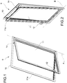
- a door and window frame 9 is shown (in this example, a window), in two operating conditions, a so-called “turn” operating condition, in which a leaf 11 of the frame is pivotable about a lateral vertical axis A, and a second operating condition, so-called “tilt” condition, in which the leaf 11 of the window frame 9 is pivotable about a horizontal lower axis B, respectively.
- the frame 9 comprises a frame 10 for fixing the window frame to a wall (not illustrated), and a casing 11a of the leaf on which an operating device 12 is mounted.
- the operation of the window in tilt or turn configurations is carried out through an actuating mechanism 14, which connects the frame 10 to the casing 11a.
- a rotation imparted to the operating device 12 actuates movement transmission means or linkage 16, through which it is possible to act on the actuating mechanism 14, so to control the operation thereof in closing conditions, and tilt-mode and turn-mode opening conditions.
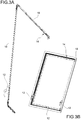
- the handle 12 can be placed in different positions (as shown, for example, in Figure 3B , in which three possible positions of the handle on the leaf are illustrated).
- the rotation imparted to the control device 12 actuates the linkage 16, which is connectable to a slidable rod 22, so as to cause the latter to reciprocate along a top edge of the casing 11a of the leaf 11.
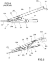
- the leaf is also connectable to the mounting frame 10 via a swivel arm 20, hingeable by means of a first junction 20a to a hinge 18 (known per se, which can be in view, retractable etc.) fixed to the fixing frame 10, and through a second junction 20b to the leaf 11.
- the first and second junctions 20a, 20b of the swivel arm 20 are located on opposite ends of said arm.
- the swivel arm 20 is also connectable to the leaf 11 by means of a grooved lever 24, hingeable to the leaf 11 by means of a third junction 24a, and connected to the swivel arm 20 by means of a first pin 24b, which is conveniently slidable along a first groove or rectilinear slot 20d present on said swivel arm 20.
- the third junction 24a and the first pin 24b are at opposite ends of said grooved lever 24.
- the grooved lever 24 has a first shaped groove 25, within which a second pin 30, carried by the slidable rod 22, is movable.
- the first shaped groove 25 has at least one straight portion 25a, extended in the direction of the length of the grooved lever 24, and an inclined portion 25b, consecutive with respect to said straight portion 25a and preferably extended towards the leaf 11.
- the inclined portion 25b ends with a terminal stop edge 25c, against which the second pin 30 abuts in the "tilt" operating condition of the door and window frame 9.
- the first shaped groove 25 may comprise, further to a first portion configured as described above (i.e., with a straight portion and an inclined portion), also a second portion (having in turn a straight portion and an inclined portion) which is symmetrical to the first portion with respect to a longitudinal axis of the grooved lever 24.
- the grooved lever 24 has a second shaped groove 32, in which a third pin 34 carried by the slidable rod 22 is slidable.
- the second shaped groove 32 is longitudinally more spaced (along the grooved lever 24) from the third junction 24a (where the grooved lever 24 is hinged to the leaf 11), with respect to the first shaped groove 25.
- the third pin 34 exerts on the grooved lever 24 a larger locking moment compared to that exerted by the second pin 30, the lever arm of the locking force being longer (i.e., the longitudinal distance between pins 30, 34 and the third junction 24a).
- the second shaped groove 32 has at least one straight portion 32a, extended in the direction of the length of the grooved lever 24, and an inclined portion 32b, consecutive with respect to said straight portion 32a and preferably extended towards the leaf 11.
- the inclined portion 32b is open at one end, so as to allow the third pin 34 to insert and disengage with respect to the second shaped groove 32, during the rotation of the grooved lever 24.
- the third pin 34 can be retractable, in such a way to move downwards when the solid edges of the grooved lever 24 slide over it (for example, being pressed downwards by such edges), and lifting within the second shaped groove 32 (for example, by means of a biasing elastic means), thus engaging such a second groove.
- the swivel arm 20 is further connectable to the leaf 11 via a connecting rod 28, hinged to the leaf 11 by means of a fourth junction 28a and connected to the swivel arm 20 via a fourth pin 28b.
- the connecting rod 28 may be hinged to the swivel arm 20 through the fourth pin 28b or, optionally, can be slidable or pivotable along a second rectilinear groove or slot present in said swivel arm 20 (according to an embodiment not shown).
- the forth junction 28a and the fourth pin 28b are at opposite ends of said rod 28.
- the connecting rod 28 could assist, for example, the lever 24 in supporting the weight of the leaf 11.
- the grooved lever 24 and the connecting rod 28 rotate around the respective third and fourth junctions 24a, 28a in a convergent manner (i.e., the first pin 24b, integral with the grooved lever 24, and the fourth pin 28b, integral with the connecting rod 28, approach to each other in the direction of the length of the swivel arm 20).
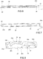
- Figures 6, 7 and 8 show a condition where the leaf 11 is closed (i.e., the leaf is substantially coplanar with the frame 10).
- the swivel arm 20, the grooved lever 24, the connecting rod 28 and the slidable rod 22 are aligned, integral and superimposed, the grooved lever 24 and the connecting rod 28 being in a vertically intermediate position between the swivel arm 20 and the slidable rod 22.
- the slidable rod 22 is in a retracted condition, thus the second and third pins 30, 34 are at an end-of-stroke position (distal with respect to the third junction 24a) along the respective first and second shaped grooves 25, 32.
- a fith pin 20e, integral to the swivel arm 20, preferably engages a cursor 36 carried by the slidable rod 22.
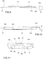
- Figures 9, 10 and 11 show a condition where the leaf 11 is openable in a turn-mode (i.e., the leaf is pivotable about a lateral vertical axis A).
- the swivel arm 20, the grooved lever 24, the connecting rod 28 and the slidable rod 22 remain integral and overlapped, pivoting around the vertical axis A.
- the second and third pins 30, 34, dragged by the slidable rod 22, travel all along the respective straight portions 25a, 32a of the first and second shaped grooves 25, 32, approaching to the third junction 24a where the grooved lever 24 is hinged to the leaf 11.
- the fifth pin 20e disengages the cursor 36.
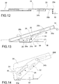
- Figures 12, 13 and 14 show a condition where the leaf 11 is openable in a tilt-mode (i.e., the leaf is pivotable about a lower horizontal axis B).
- the swivel arm 20 and the slidable rod 22 spread relative to one another, the slidable rod 22 pivoting (with the leaf 11) around the second junction 20b with respect to the swivel arm 20.
- the second and third pins 30, 34 dragged by the slidable rod 22, travel all along the respective inclined portions 25b, 32b of the first and second shaped grooves 25, 32, unlocking the rotation of the grooved lever 24 and the rod 28.
- Said grooved lever 24 and rod 28 pivot mutually converging, the first pin 24b being free of sliding along the respective first rectilinear groove 20d on the swivel arm 20.
- the second pin 30 exerts a thrust against the edges of the respective inclined portion 25b of the first shaped groove 25: such a thrust, being eccentric with respect to the third junction 24a, imparts a moment around said third portion 24a, determining the opening of the leaf 11.
- the second pin 30 abuts against the terminal stop edge 25c of the first shaped groove 25.
- the third pin 34 goes out of the second shaped groove 32, through the respective inclined portion 32b, disengaging the grooved lever 24.
- Figures 15 to 17 show a closing phase of the door and window frame 9, wherein the leaf 11 approaches the frame 10.
- the swivel arm 20 and the slidable rod 22 tend to re-align again, the slidable rod 22 pivoting (integral to the leaf 11) around the second junction 20b with respect to the swivel arm 20.
- the second pin 30 exerts a thrust against the edges of the respective inclined portion 25b of the first shaped groove 25.
- the thrust exerted by the second pin 30 will act in an opposite direction with respect to the thrust exerted during the tilt-mode opening phase of the leaf.
- Such a thrust being eccentric with respect to the third junction 24a, imparts a moment around said third junction 24a, determining the closure of the leaf.
- the second and third pins 30, 34 come back in the position shown in Figure 8 .
- the thrust exerted by the second pin 30 on the first shaped groove 25 (which thrust is generated by the translation of the slidable rod 22), it is possible to open and close the leaf, even during the tilt operative mode, by rotating even only the handle 12, i.e., without pushing manually the leaf.
- the moment generated by the third pin 34 acting on the second shaped groove 32 may contribute to increase the opening/closing force, and guarantees an optimal locking action between the swivel arm and the slidable rod/leaf.
Landscapes
- Engineering & Computer Science (AREA)
- Mechanical Engineering (AREA)
- Closing And Opening Devices For Wings, And Checks For Wings (AREA)
Applications Claiming Priority (1)
| Application Number | Priority Date | Filing Date | Title |
|---|---|---|---|
| ITTO20150125 | 2015-02-23 |
Publications (1)
| Publication Number | Publication Date |
|---|---|
| EP3059366A1 true EP3059366A1 (de) | 2016-08-24 |
Family
ID=53016709
Family Applications (2)
| Application Number | Title | Priority Date | Filing Date |
|---|---|---|---|
| EP16156634.4A Withdrawn EP3059367A1 (de) | 2015-02-23 | 2016-02-22 | Betätigungsmechanismus für drehkipptür oder fensterrahmen mit einem hebel und einer verbindungsstange |
| EP16156630.2A Withdrawn EP3059366A1 (de) | 2015-02-23 | 2016-02-22 | Betätigungsmechanismus für drehkipptür- oder -fensterrahmen mit einem hebel mit zwei unabhängigen nuten |
Family Applications Before (1)
| Application Number | Title | Priority Date | Filing Date |
|---|---|---|---|
| EP16156634.4A Withdrawn EP3059367A1 (de) | 2015-02-23 | 2016-02-22 | Betätigungsmechanismus für drehkipptür oder fensterrahmen mit einem hebel und einer verbindungsstange |
Country Status (1)
| Country | Link |
|---|---|
| EP (2) | EP3059367A1 (de) |
Families Citing this family (2)
| Publication number | Priority date | Publication date | Assignee | Title |
|---|---|---|---|---|
| CA3188624A1 (en) * | 2023-02-03 | 2025-01-17 | Long Ten Technology Inc. | WINDOW MECHANISM |
| CN116876940A (zh) * | 2023-08-11 | 2023-10-13 | 深圳好博窗控技术股份有限公司 | 一种门窗自动内倒机构及门窗 |
Citations (3)
| Publication number | Priority date | Publication date | Assignee | Title |
|---|---|---|---|---|
| CH413643A (de) * | 1962-07-13 | 1966-05-15 | Mayer & Co | Ausstellvorrichtung für Dreh-Kippfenster |
| DE2151996A1 (de) | 1971-10-18 | 1973-04-26 | Siegenia Frank Kg | Ausstellvorrichtung fuer kipp-schwenkfluegel von fenstern, tueren od. dgl |
| DE3345870A1 (de) * | 1983-12-19 | 1985-06-27 | Geze Gmbh, 7250 Leonberg | Ausstellvorrichtung fuer fenster, tueren oder dergleichen mit dreh-kippfluegel |
-
2016
- 2016-02-22 EP EP16156634.4A patent/EP3059367A1/de not_active Withdrawn
- 2016-02-22 EP EP16156630.2A patent/EP3059366A1/de not_active Withdrawn
Patent Citations (3)
| Publication number | Priority date | Publication date | Assignee | Title |
|---|---|---|---|---|
| CH413643A (de) * | 1962-07-13 | 1966-05-15 | Mayer & Co | Ausstellvorrichtung für Dreh-Kippfenster |
| DE2151996A1 (de) | 1971-10-18 | 1973-04-26 | Siegenia Frank Kg | Ausstellvorrichtung fuer kipp-schwenkfluegel von fenstern, tueren od. dgl |
| DE3345870A1 (de) * | 1983-12-19 | 1985-06-27 | Geze Gmbh, 7250 Leonberg | Ausstellvorrichtung fuer fenster, tueren oder dergleichen mit dreh-kippfluegel |
Also Published As
| Publication number | Publication date |
|---|---|
| EP3059367A1 (de) | 2016-08-24 |
Similar Documents
| Publication | Publication Date | Title |
|---|---|---|
| US8707621B2 (en) | Outswinging window assembly having an operational mode and a wash mode and method of operation | |
| EP3159218A2 (de) | Abdeckungsanordnung einer einklemmschutzgleitverkleidung für eine fahrzeugschiebetür | |
| CN107295803A (zh) | 用于门或窗的铰链 | |
| HRP20180393T1 (hr) | Prozor sa zakretnim krilom | |
| EP3059366A1 (de) | Betätigungsmechanismus für drehkipptür- oder -fensterrahmen mit einem hebel mit zwei unabhängigen nuten | |
| CN107208439A (zh) | 用于门或窗的铰链 | |
| TW202106205A (zh) | 滑軌總成 | |
| US2505912A (en) | Closure operator and linkage therefor | |
| CN106460431B (zh) | 在枢转窗户处的机构 | |
| EP4215706A1 (de) | Reibungsscharnier für nach oben gerichtete, nach aussen öffnende fenster | |
| EP2019180A2 (de) | Betriebsvorrichtung für Fenster | |
| CN107849889A (zh) | 具有主驱动器和辅助驱动器的门驱动器 | |
| EP2479370B1 (de) | Dachfenster mit Balkonfunktion | |
| CN104234537B (zh) | 柜门锁结构 | |
| RU2717929C2 (ru) | Выдвижная ножничная система, а также сдвижная дверь или сдвижное окно с такой выдвижной ножничной системой | |
| CN108851656A (zh) | 滑轨总成 | |
| RU2685316C2 (ru) | Элемент управления для фурнитурной системы | |
| EP3426871B1 (de) | Ausstellvorrichtung | |
| EP2821577A1 (de) | Betriebsgerät für eine Dreh-Kipp- Tür oder Fenster | |
| CN211115505U (zh) | 隐藏式平开上悬五金系统 | |
| CN101243235B (zh) | 张开装置 | |
| CN110080656A (zh) | 隐藏式平开上悬五金系统 | |
| EP4624714A1 (de) | Begrenzungsvorrichtung zur begrenzung der öffnung einer tür oder eines fensters | |
| JP7233122B2 (ja) | ドア・窓制御装置及び方法 | |
| EP1327738B1 (de) | Schliessystem für Kippfenster, mit einem Betätigungsgetriebe und einem Ausstellscherenmechanismus |
Legal Events
| Date | Code | Title | Description |
|---|---|---|---|
| PUAI | Public reference made under article 153(3) epc to a published international application that has entered the european phase |
Free format text: ORIGINAL CODE: 0009012 |
|
| AK | Designated contracting states |
Kind code of ref document: A1 Designated state(s): AL AT BE BG CH CY CZ DE DK EE ES FI FR GB GR HR HU IE IS IT LI LT LU LV MC MK MT NL NO PL PT RO RS SE SI SK SM TR |
|
| AX | Request for extension of the european patent |
Extension state: BA ME |
|
| 17P | Request for examination filed |
Effective date: 20170222 |
|
| RBV | Designated contracting states (corrected) |
Designated state(s): AL AT BE BG CH CY CZ DE DK EE ES FI FR GB GR HR HU IE IS IT LI LT LU LV MC MK MT NL NO PL PT RO RS SE SI SK SM TR |
|
| GRAP | Despatch of communication of intention to grant a patent |
Free format text: ORIGINAL CODE: EPIDOSNIGR1 |
|
| INTG | Intention to grant announced |
Effective date: 20170627 |
|
| STAA | Information on the status of an ep patent application or granted ep patent |
Free format text: STATUS: THE APPLICATION IS DEEMED TO BE WITHDRAWN |
|
| 18D | Application deemed to be withdrawn |
Effective date: 20171108 |