EP3059116B1 - Siege ergonomique - Google Patents
Siege ergonomique Download PDFInfo
- Publication number
- EP3059116B1 EP3059116B1 EP16156702.9A EP16156702A EP3059116B1 EP 3059116 B1 EP3059116 B1 EP 3059116B1 EP 16156702 A EP16156702 A EP 16156702A EP 3059116 B1 EP3059116 B1 EP 3059116B1
- Authority
- EP
- European Patent Office
- Prior art keywords
- seat
- configuration
- vehicle
- positions
- driver
- Prior art date
- Legal status (The legal status is an assumption and is not a legal conclusion. Google has not performed a legal analysis and makes no representation as to the accuracy of the status listed.)
- Active
Links
- 230000008859 change Effects 0.000 claims description 47
- 238000000034 method Methods 0.000 claims description 6
- 230000003287 optical effect Effects 0.000 claims description 2
- 230000006870 function Effects 0.000 description 51
- 230000036541 health Effects 0.000 description 48
- 239000002184 metal Substances 0.000 description 32
- 230000036544 posture Effects 0.000 description 21
- 206010023509 Kyphosis Diseases 0.000 description 18
- 208000007623 Lordosis Diseases 0.000 description 17
- 230000000007 visual effect Effects 0.000 description 5
- 238000004804 winding Methods 0.000 description 5
- 238000010276 construction Methods 0.000 description 4
- 206010034719 Personality change Diseases 0.000 description 3
- 230000008901 benefit Effects 0.000 description 3
- 210000000038 chest Anatomy 0.000 description 3
- 238000011156 evaluation Methods 0.000 description 3
- 210000004705 lumbosacral region Anatomy 0.000 description 3
- 238000012544 monitoring process Methods 0.000 description 3
- 240000001439 Opuntia Species 0.000 description 2
- 235000004727 Opuntia ficus indica Nutrition 0.000 description 2
- 230000009471 action Effects 0.000 description 2
- 230000004913 activation Effects 0.000 description 2
- 238000005259 measurement Methods 0.000 description 2
- 210000003205 muscle Anatomy 0.000 description 2
- 238000003825 pressing Methods 0.000 description 2
- 230000035807 sensation Effects 0.000 description 2
- 239000000126 substance Substances 0.000 description 2
- 229920002334 Spandex Polymers 0.000 description 1
- 230000001133 acceleration Effects 0.000 description 1
- 230000004308 accommodation Effects 0.000 description 1
- 230000003213 activating effect Effects 0.000 description 1
- 230000006978 adaptation Effects 0.000 description 1
- 230000009286 beneficial effect Effects 0.000 description 1
- 230000008878 coupling Effects 0.000 description 1
- 238000010168 coupling process Methods 0.000 description 1
- 238000005859 coupling reaction Methods 0.000 description 1
- 238000013016 damping Methods 0.000 description 1
- 230000001419 dependent effect Effects 0.000 description 1
- 238000010586 diagram Methods 0.000 description 1
- 238000006073 displacement reaction Methods 0.000 description 1
- 239000004744 fabric Substances 0.000 description 1
- 239000012530 fluid Substances 0.000 description 1
- 210000002414 leg Anatomy 0.000 description 1
- 230000006386 memory function Effects 0.000 description 1
- 210000004197 pelvis Anatomy 0.000 description 1
- 230000008569 process Effects 0.000 description 1
- 239000002994 raw material Substances 0.000 description 1
- 239000007787 solid Substances 0.000 description 1
- 230000006641 stabilisation Effects 0.000 description 1
- 238000011105 stabilization Methods 0.000 description 1
- 239000000725 suspension Substances 0.000 description 1
- 210000000115 thoracic cavity Anatomy 0.000 description 1
- 210000000689 upper leg Anatomy 0.000 description 1
Images


Classifications
-
- B—PERFORMING OPERATIONS; TRANSPORTING
- B60—VEHICLES IN GENERAL
- B60N—SEATS SPECIALLY ADAPTED FOR VEHICLES; VEHICLE PASSENGER ACCOMMODATION NOT OTHERWISE PROVIDED FOR
- B60N2/00—Seats specially adapted for vehicles; Arrangement or mounting of seats in vehicles
- B60N2/02—Seats specially adapted for vehicles; Arrangement or mounting of seats in vehicles the seat or part thereof being movable, e.g. adjustable
- B60N2/0224—Non-manual adjustments, e.g. with electrical operation
- B60N2/0226—User interfaces specially adapted for seat adjustment
- B60N2/0228—Hand-activated mechanical switches
-
- B—PERFORMING OPERATIONS; TRANSPORTING
- B60—VEHICLES IN GENERAL
- B60N—SEATS SPECIALLY ADAPTED FOR VEHICLES; VEHICLE PASSENGER ACCOMMODATION NOT OTHERWISE PROVIDED FOR
- B60N2/00—Seats specially adapted for vehicles; Arrangement or mounting of seats in vehicles
- B60N2/02—Seats specially adapted for vehicles; Arrangement or mounting of seats in vehicles the seat or part thereof being movable, e.g. adjustable
- B60N2/0224—Non-manual adjustments, e.g. with electrical operation
- B60N2/0244—Non-manual adjustments, e.g. with electrical operation with logic circuits
- B60N2/0248—Non-manual adjustments, e.g. with electrical operation with logic circuits with memory of positions
-
- B—PERFORMING OPERATIONS; TRANSPORTING
- B60—VEHICLES IN GENERAL
- B60N—SEATS SPECIALLY ADAPTED FOR VEHICLES; VEHICLE PASSENGER ACCOMMODATION NOT OTHERWISE PROVIDED FOR
- B60N2/00—Seats specially adapted for vehicles; Arrangement or mounting of seats in vehicles
- B60N2/02—Seats specially adapted for vehicles; Arrangement or mounting of seats in vehicles the seat or part thereof being movable, e.g. adjustable
- B60N2/04—Seats specially adapted for vehicles; Arrangement or mounting of seats in vehicles the seat or part thereof being movable, e.g. adjustable the whole seat being movable
- B60N2/06—Seats specially adapted for vehicles; Arrangement or mounting of seats in vehicles the seat or part thereof being movable, e.g. adjustable the whole seat being movable slidable
-
- B—PERFORMING OPERATIONS; TRANSPORTING
- B60—VEHICLES IN GENERAL
- B60N—SEATS SPECIALLY ADAPTED FOR VEHICLES; VEHICLE PASSENGER ACCOMMODATION NOT OTHERWISE PROVIDED FOR
- B60N2/00—Seats specially adapted for vehicles; Arrangement or mounting of seats in vehicles
- B60N2/02—Seats specially adapted for vehicles; Arrangement or mounting of seats in vehicles the seat or part thereof being movable, e.g. adjustable
- B60N2/04—Seats specially adapted for vehicles; Arrangement or mounting of seats in vehicles the seat or part thereof being movable, e.g. adjustable the whole seat being movable
- B60N2/10—Seats specially adapted for vehicles; Arrangement or mounting of seats in vehicles the seat or part thereof being movable, e.g. adjustable the whole seat being movable tiltable
-
- B—PERFORMING OPERATIONS; TRANSPORTING
- B60—VEHICLES IN GENERAL
- B60N—SEATS SPECIALLY ADAPTED FOR VEHICLES; VEHICLE PASSENGER ACCOMMODATION NOT OTHERWISE PROVIDED FOR
- B60N2/00—Seats specially adapted for vehicles; Arrangement or mounting of seats in vehicles
- B60N2/02—Seats specially adapted for vehicles; Arrangement or mounting of seats in vehicles the seat or part thereof being movable, e.g. adjustable
- B60N2/04—Seats specially adapted for vehicles; Arrangement or mounting of seats in vehicles the seat or part thereof being movable, e.g. adjustable the whole seat being movable
- B60N2/16—Seats specially adapted for vehicles; Arrangement or mounting of seats in vehicles the seat or part thereof being movable, e.g. adjustable the whole seat being movable height-adjustable
- B60N2/1605—Seats specially adapted for vehicles; Arrangement or mounting of seats in vehicles the seat or part thereof being movable, e.g. adjustable the whole seat being movable height-adjustable characterised by the cinematic
- B60N2/161—Rods
- B60N2/1615—Parallelogram-like structure
-
- B—PERFORMING OPERATIONS; TRANSPORTING
- B60—VEHICLES IN GENERAL
- B60N—SEATS SPECIALLY ADAPTED FOR VEHICLES; VEHICLE PASSENGER ACCOMMODATION NOT OTHERWISE PROVIDED FOR
- B60N2/00—Seats specially adapted for vehicles; Arrangement or mounting of seats in vehicles
- B60N2/02—Seats specially adapted for vehicles; Arrangement or mounting of seats in vehicles the seat or part thereof being movable, e.g. adjustable
- B60N2/22—Seats specially adapted for vehicles; Arrangement or mounting of seats in vehicles the seat or part thereof being movable, e.g. adjustable the back-rest being adjustable
- B60N2/2209—Seats specially adapted for vehicles; Arrangement or mounting of seats in vehicles the seat or part thereof being movable, e.g. adjustable the back-rest being adjustable by longitudinal displacement of the cushion, e.g. back-rest hinged on the bottom to the cushion and linked on the top to the vehicle frame
-
- B—PERFORMING OPERATIONS; TRANSPORTING
- B60—VEHICLES IN GENERAL
- B60N—SEATS SPECIALLY ADAPTED FOR VEHICLES; VEHICLE PASSENGER ACCOMMODATION NOT OTHERWISE PROVIDED FOR
- B60N2/00—Seats specially adapted for vehicles; Arrangement or mounting of seats in vehicles
- B60N2/24—Seats specially adapted for vehicles; Arrangement or mounting of seats in vehicles for particular purposes or particular vehicles
- B60N2/242—Bus seats
-
- B—PERFORMING OPERATIONS; TRANSPORTING
- B60—VEHICLES IN GENERAL
- B60N—SEATS SPECIALLY ADAPTED FOR VEHICLES; VEHICLE PASSENGER ACCOMMODATION NOT OTHERWISE PROVIDED FOR
- B60N2/00—Seats specially adapted for vehicles; Arrangement or mounting of seats in vehicles
- B60N2/64—Back-rests or cushions
- B60N2/66—Lumbar supports
- B60N2/667—Lumbar supports having flexible support member bowed by applied forces
- B60N2/6673—Lumbar supports having flexible support member bowed by applied forces with motor driven adjustments
-
- B—PERFORMING OPERATIONS; TRANSPORTING
- B60—VEHICLES IN GENERAL
- B60N—SEATS SPECIALLY ADAPTED FOR VEHICLES; VEHICLE PASSENGER ACCOMMODATION NOT OTHERWISE PROVIDED FOR
- B60N2/00—Seats specially adapted for vehicles; Arrangement or mounting of seats in vehicles
- B60N2/75—Arm-rests
- B60N2/79—Adaptations for additional use of the arm-rests
- B60N2/797—Adaptations for additional use of the arm-rests for use as electrical control means, e.g. switches
-
- B—PERFORMING OPERATIONS; TRANSPORTING
- B60—VEHICLES IN GENERAL
- B60N—SEATS SPECIALLY ADAPTED FOR VEHICLES; VEHICLE PASSENGER ACCOMMODATION NOT OTHERWISE PROVIDED FOR
- B60N2/00—Seats specially adapted for vehicles; Arrangement or mounting of seats in vehicles
- B60N2/80—Head-rests
- B60N2/806—Head-rests movable or adjustable
-
- B—PERFORMING OPERATIONS; TRANSPORTING
- B60—VEHICLES IN GENERAL
- B60N—SEATS SPECIALLY ADAPTED FOR VEHICLES; VEHICLE PASSENGER ACCOMMODATION NOT OTHERWISE PROVIDED FOR
- B60N2/00—Seats specially adapted for vehicles; Arrangement or mounting of seats in vehicles
- B60N2/90—Details or parts not otherwise provided for
- B60N2/914—Hydro-pneumatic adjustments of the shape
-
- B—PERFORMING OPERATIONS; TRANSPORTING
- B60—VEHICLES IN GENERAL
- B60N—SEATS SPECIALLY ADAPTED FOR VEHICLES; VEHICLE PASSENGER ACCOMMODATION NOT OTHERWISE PROVIDED FOR
- B60N2/00—Seats specially adapted for vehicles; Arrangement or mounting of seats in vehicles
- B60N2/90—Details or parts not otherwise provided for
- B60N2/976—Details or parts not otherwise provided for massaging systems
-
- B—PERFORMING OPERATIONS; TRANSPORTING
- B60—VEHICLES IN GENERAL
- B60N—SEATS SPECIALLY ADAPTED FOR VEHICLES; VEHICLE PASSENGER ACCOMMODATION NOT OTHERWISE PROVIDED FOR
- B60N2/00—Seats specially adapted for vehicles; Arrangement or mounting of seats in vehicles
- B60N2/90—Details or parts not otherwise provided for
- B60N2/995—Lower-leg-rests, e.g. calf-rests
-
- B—PERFORMING OPERATIONS; TRANSPORTING
- B60—VEHICLES IN GENERAL
- B60N—SEATS SPECIALLY ADAPTED FOR VEHICLES; VEHICLE PASSENGER ACCOMMODATION NOT OTHERWISE PROVIDED FOR
- B60N2205/00—General mechanical or structural details
- B60N2205/30—Seat or seat parts characterised by comprising plural parts or pieces
Definitions
- the invention relates to a vehicle seat having a seat part and a backrest and with variable seat configuration positions, comprising a first position of a shoulder rest, a second position of a lumbar support, a third seat height position, a fourth longitudinal position of the vehicle seat, a fifth seat tilt position and a sixth seat recline position, by means of which first and one different second seat configuration are definable.
- Such vehicle seats are known from the prior art, which make it possible to adjust the sitting position of a driver according to his wishes in terms of ergonomics and driving sensation.
- the corresponding adjustment options such as the inclination of the seat, the backrest tilt position or the seat height position are set in succession before the start of the journey and not or hardly changed during a ride.
- a vehicle seat with a seat part and a backrest and with variable seat configuration positions comprising a first position of a shoulder rest, a second position of a lumbar support, a third seat height position, a fourth longitudinal position of the vehicle seat, a fifth seat recline position and a sixth seat recline position by means of which a first and a different second seat configuration are definable, wherein the seat configurations differ in at least two different positions and the vehicle seat has a control device, by means of which the first and the second seat configuration of the vehicle seat alternately by means of a simultaneous and mutually independent change at least two different positions are adjustable.
- the first seat configuration preferably corresponds to an upright posture of the vehicle driver, while the second seat configuration preferably represents an inclined posture of the vehicle driver.
- the upright posture advantageously corresponds to a lordosis-assisted seating configuration, the sloped posture of a kyphosis-assisted seating configuration.
- the change between the two seat configurations is also referred to below as "health function".
- the lordosis is a curvature of the spine forward, that is, anteriorly.
- the spine includes two lordosis bends, once in the lumbar spine and once in the cervical area.
- kyphosis a curvature of the spine is referred to the back, ie to the dorsal.
- the spine includes two kyphosis bends, once in the chest (chest kyphosis) and once at the end of the spine (sacral).
- the vehicle seat according to the invention is therefore in different, preferably at least six mutually different seat configuration positions, short positions, adjustable, whereby an optimal adaptation of the seat to the physique of the driver is feasible, under a seat tilt position, the inclination of the seat or the inclination of the seat, on the the driver is sitting, understand.
- the inclination of the headrest in particular in the vehicle longitudinal direction forward or backward, adjustable.
- a different selection of the positions for a vehicle seat can be made, so it can be selected from the totality of the positions provided a subgroup. According to the invention, however, the positions should continue to be adjustable simultaneously and independently of each other.
- an adjustment of the first and the second seat configuration alternately takes place by a change of at least two different positions. These positions are changed simultaneously, but independently, that is, a change in one position does not cause the change of another position in a certain way.
- the body structure of a vehicle driver can be relieved, if the seat configurations differ in more than two, more than three, more than four, more than five or six or more than six seat configuration positions. It may also be possible be set more than the six mentioned, for example, seven seat configuration positions simultaneously and independently.
- the simultaneous change of at least two of the mentioned seat configuration positions a particularly good relief of the body structures is brought about. It is known that by adjusting such a position already the attitude of the driver as a whole, including other positions, are affected.
- the inclination of the seat is listed here. If the inclination of the seat surface is reduced, that is to say the front area of the seat surface is moved downwards while the rear area of the seat surface does not change in position, the angle between the seat surface and the backrest increases in particular. Accordingly, the angle between the legs, especially the thighs, and the torso of the driver changes as well.
- the pelvis of the driver moves, whereby the lordosis of the loin, so the curvature of the lumbar spine, is affected.
- the curvature of the thoracic kyphosis is altered.
- the seat configuration positions depend on each other for the best possible adjustment and support for the driver, they can still be adjusted and controlled independently of each other according to the present invention, preferably by means of the control device.
- At least two of the seat configuration positions can be set simultaneously and independently of each other in at least two successive adjustment steps, paying attention to a sensible sequence and division of the adjustment steps.
- the backrest inclination position and the shoulder support position could first be set simultaneously and independently of each other, subsequently simultaneously and independently of each other, the lumbar support position and the longitudinal position of the seat, and finally, simultaneously and independently, the seat recline position and the seat recline position.
- the control device comprises a memory device in which the first and the second seat configuration can be stored.
- the seat configurations stored in the memory device can be accessed at any time by means of the control device, whereby an adjustment of the seat configurations before the start of the journey is unnecessary, wherein the control device can further process the data obtained.
- control device For changing positions, the control device is provided, wherein this control device is preferably an electrically and / or electronically controllable control device.
- the control device is designed such that it can simultaneously, ie at the same time, adjust the various positions.
- a vehicle driver adjusts a seat configuration and preferably recognizes the control device, which seat configuration is involved, in particular it is recognized whether a lordosis-supporting or a kyphosis-assisting position exists.
- the control device proposes the driver to the other seat configuration, saves it after release or change and release and then starts the health function.
- the control device calculates a second seat configuration as a function of the first seat configuration and the recognition of the first seat configuration and proposes and / or sets the driver.
- the first and the second seat configuration can be set automatically alternately by means of the control device, as a result of which a driver no longer has to manually adjust the positions, but this is carried out automatically by the control device.
- the vehicle seat thus automatically alternates between the first and the second seat configuration during a journey. Accordingly, a change from the first to the second seat configuration and / or from the second to the first seat configuration after a predeterminable and variable time interval is feasible.
- the time interval is between 1 and 30 minutes, more advantageously between 5 and 15 minutes. In this case, a time interval of 10 minutes has proven particularly advantageous.
- the first seat configuration is set, then after the time interval of 10 minutes, the corresponding positions are changed so that the second seat configuration is set.
- the value of the time interval should be within the above time intervals.
- the driver can be made aware of a change of attitude and / or the pause time, which lies between the change of a configuration in the other configuration.
- other time intervals are conceivable.
- a vehicle driver seated on the vehicle seat can be requested by means of an acoustic and / or optical signal to carry out a change of the seat configurations.
- an animation signal in the form of a display on the touch pad or the like and / or an acoustic signal may be considered.
- the animation signal may preferably continue until the driver activates the health function.
- the longer the driver does not activate the health function the stronger the animation signal may become.
- the seat acts as a kind of "personal trainer” as the seat causes the driver and causes a Change of posture analogous to the change of the vehicle seat.
- the driver is encouraged to change his attitude, which causes his body structures, especially his muscles and his spine, be relieved.
- the first or the second seat configuration according to a field of application of the vehicle, which can be specified by the driver, adjustable or activated.
- Conceivable applications are, for example, longer highway trips, off-road driving or city driving.
- the health function is active in congestion or at moderate speeds and is automatically deactivated at high speeds, for example, at 180 km / h or more, since the driver should be concentrated and quiet at such speeds for safety not to endanger.
- the speed at which the health function is to be deactivated can be adjusted according to the needs of the vehicle driver.
- each of the seat configuration positions is changeable by at least one actuator, which is operatively connected to a component belonging to the respective seat configuration position.
- the actuator is, for example, an electric motor which can be activated by the control device and at the same time is operatively connected to the component belonging to the seat configuration position.
- the actuator is designed as a fluid pump, which is fluidically connected to an air chamber, wherein the seat configuration position can be changed by means of the air chamber.
- each of these components is advantageously adjusted by the actuator, which is driven by the control device.
- the actuator which is driven by the control device.
- a motor which drives the respective pivot axis and thus the inclination is adjustable.
- the actuators which are preferably controlled and driven electronically and / or electrically by the control device, it is conceivable to set a speed of change from the upright to the inclined position or vice versa.
- the intensity of changing the positions and the adjustment speed of the positions should be selected so that it is comfortable for the driver. Critical, in this case uncomfortable perceived pressure sensations when adjusting the positions are thus reduced here.
- the intensity can be predetermined by the vehicle driver by means of the control device and can also advantageously be changed during driving operation.
- the driver can adjust and control the intensity according to his needs.
- the control device It is also advantageous to automatically adjust the adjustment speed depending on the speed of the vehicle and / or the condition of the driver by means of the control device.
- a manual adjustment of the adjustment by the driver can be made.
- the triggering of the health function may depend on the speed and / or the condition of the vehicle driver.
- the health function makes sense to couple the health function with sensors that detect and record the body measurements and / or the condition of the vehicle driver, and / or with a driver monitoring system. For example, if the driver monitoring system detects that the driver has fallen asleep and is not active, an abrupt change of posture may be made to wake the driver.
- the area is adjustable by means of a contour-changing device. It can be any electromechanical or pneumatic device.
- the region of the loin could be supported by means of different metal strips, wherein the metal strips are connected to each other such that by a movement of a metal strip and the surrounding metal strips are affected.
- a motor is arranged with an eccentric element behind such a sheet metal strip and depending on the position of the eccentric element of the present sheet metal strip is moved.
- the eccentric it is also conceivable to move another deformation element, such as a rod or the like, driven by a motor against a metal strip.
- the deformation element is connected to a metal strip and is moved by the motor forward or backward.
- the backrest cushion and the seat part pad are designed to be stretchable and deformable.
- substances are considered, which return to their original shape after stretching, so do not wear out.
- Such substances are, for example, fabrics with elastane or comparable raw materials.
- Such a vehicle seat for a vehicle driver can also be provided for a passenger and used.
- the driver can proceed as follows. First, he puts the first seat configuration, so an upright posture for the driver and preferably, a lumbar support configuration of the vehicle seat by changing the various seat configuration positions. This first seat configuration can then be stored in the storage device of the control device, preferably after its setting. After the first seat configuration has been stored, the vehicle driver can now set a second seat configuration that differs from the first seat configuration, ie a tilted posture of the vehicle driver and preferably a kyphosis-assisting configuration of the vehicle seat analogously to the first seat configuration and also store these preferably in the storage device. Preferably, such presetting of the seat may be performed in a screened manner to indicate to the vehicle operator how to set and / or set a first or second seat configuration.
- a storage of the respective seat configuration can advantageously be formed by means of an actuating element, such as a pushbutton, whose actuation triggers a storage of the current seat configuration of the vehicle seat.
- an actuating element such as a pushbutton
- two different actuation elements can be present on the seat, wherein the first actuation element for the storage of the first seat configuration and the second actuation element for the storage of the second seat configuration are provided.
- the actuators thus fulfill a memory function. These actuators may for example be integrated in an armrest or be formed on a touch pad or the like. Of course, other configurations and accommodations for the actuators are possible, which are not further elaborated here.
- the actuating elements are in this case connected to the control device, in particular also with the storage device of the control device.
- a third actuating element is provided, by means of which a health function, ie the change between the upright, preferably lordosis-supporting and the inclined, preferably kyphosis-supporting sitting position, is activated.
- a health function ie the change between the upright, preferably lordosis-supporting and the inclined, preferably kyphosis-supporting sitting position.
- Such a function is advantageous when the driver does not want to be distracted by large changes in posture due to the traffic situation, but still wants to perform small movements, such as to stay awake or to load and unload the body, albeit less.
- This oscillating adjustment is advantageously activated by means of a further actuating element.
- the values are given in degrees, for the seat height position and the longitudinal position of the seat, the values are given as a length. Both values can be used for the lumbar support position and the shoulder support position, but these are also advantageously given as a length.
- the adjustment values are advantageously in a range between -5 ° to + 5 ° or -5 mm to 5 mm, advantageously -3 ° to 3 ° or -3 mm to 3 mm, and particularly advantageously -2 ° to 2 ° or -2 mm to 2 mm.
- the sign indicates, in which direction the respective component is moved, ie to the rear or front, up or down or the like.
- the health function is automatically activated by switching on the ignition by means of the control device.
- the health function must therefore be actively deactivated by the driver if he no longer wants to use the health function.
- the first and the second configuration ie the upright and the inclined seat configuration remain stored in the memory device of the control device even after completion of the journey, ie after leaving and stopping the vehicle, so as to avoid re-adjusting the positions at the next drive.
- the body dimensions of the vehicle driver are detected by the vehicle seat, for example via pressure sensors or other suitable sensors, which are integrated in the vehicle seat, preferably in the padding of the vehicle seat, and the general physical condition of the vehicle driver, in particular information about the Spine, to be determined. It is also possible that the driver enters his body measurements in a touch pad or the like and the control device already performs a basic adjustment of the vehicle seat and calculates by means of a calculation unit how the first and second seat configurations are to be adjusted and / or adjusted and then to the vehicle driver suggests.
- the basic setting preferably corresponds to the position of the vehicle seat, which corresponds to the basic seat type of the driver.
- the provided app can include various functions, such as a start-stop function, evaluation of sitting postures and driving situations and an alarm function. From an evaluation of sitting postures and driving situations derived recommendations for action can be provided.
- the distribution can be adjusted accordingly at the next start of the journey.
- certain routes that are often traveled, for example, the way to the workplace, are included in the evaluation and for these routes a corresponding program can be accessed and used.
- An alarm function can be understood, for example, as meaning that the vehicle seat is slowly moved out of the rest position or adjusted seat configuration into an upright position after a certain period of time and the vehicle driver can be woken up so gently.
- an increase in the movement of a driver can be detected by means of the sensors, since, for example, the driver more slips back and forth on the vehicle seat.
- it can be detected by the sensors that the vehicle driver assumes an asymmetrical, ie curved attitude.
- the control device recognizes that the driver desires a different or higher level of seating comfort and advantageously initiates the activation of the health function.
- the vehicle seat is always set so it is in the default setting, the first or second seat configuration and particularly advantageous must be ensured that when changing from one seat configuration to the other, the driver never the contact between his Losing feet and pedals to ensure safety in all driving situations.
- This increases the reliability especially when driving and thus reduces the risk of accidental accident or the like, since, for example, in a critical situation, the pedals can not or can not be properly operated. After disabling the health function, it is conceivable that the seat will be reset to the original seating configuration.
- the object of the invention is also achieved by a method for adjusting seat configurations of a vehicle seat comprising a seat part and a backrest and with variable seat configuration positions, comprising a first position of a shoulder rest, a second position of a lumbar support, a third seat height position, a fourth longitudinal position of the vehicle seat, a fifth seat reclining position and a sixth seat reclining position by which first and second different seat configurations are defined, wherein the seat configurations differ in at least two different positions and the vehicle seat includes control means for alternately using the first and second seat configurations of the vehicle seat a simultaneous and independent change of at least two different positions are set.
- a change from one seat configuration to the other seat configuration is automatically performed.
- An automatic change ensures that the driver changes his posture without further ado.
- the driver can continue to focus on the road and is not distracted by operating actuators or the like.
- it is ensured that the driver does not forget the operation of the health function, ie the change from one seat configuration to the other seat configuration.
- the time interval is between 1 and 30 minutes, more preferably between 5 and 15 minutes and particularly advantageously 10 minutes.
- the time interval can be staggered. So it is conceivable, for example, that the control device sets the time interval when activating the health function to a high value, for example 30 minutes, and after each pass, ie a change from one seat configuration to the other and again to the previous, the time interval by means of the control device is reduced until it has dropped to a certain value, such as about 10 minutes. Conceivable here are 5 minute steps, although other step values are conceivable.
- the health function is automatically activated. It is of course a prerequisite that a first and a second seat configuration are stored and can be accessed. However, if this is not the case, the driver is signaled to set and save the corresponding seat configurations. It is also conceivable that after saving the seat configurations, the health function is automatically activated or the driver is prompted by means of one or more animation signals to activate the health function.
- An animation signal can represent a visual and / or an acoustic signal.
- a visual signal can be displayed, for example, via the touch pad or a comparable display device.
- the driver activates the health function and thereby uses. If the driver no longer wishes to use the health function, then he must actively deactivate it.
- the basic process steps are therefore as follows. First, the driver, preferably already before the start of the journey, one after the first seat configuration and then the second seat configuration of the vehicle seat and stores each after setting the respective seat configuration, these preferably in the storage device. Adjustment of the seat configurations is made by the controller, each of the seat configuration positions being adjusted individually and independently of other parameters.
- the health function ie the change between the first and the second seat configuration, is activated either automatically or manually.
- the vehicle seat After activation of the health function, the vehicle seat is preferably brought into the first seat configuration after a predetermined time. Thereafter, a countdown begins to run and when this countdown has expired, the actuators are driven accordingly by means of the control means together with the information stored in the memory device, which are called by the control means, whereby the respective positions are simultaneously changed such that the Vehicle seat is now in the second seat configuration.
- the respective seat configuration positions are always changed simultaneously and independently of each other. A change between the two seat configuration is carried out until the driver deactivates the health function or the ride is terminated, ie the vehicle is switched off.
- the change between the first and the second seat configuration or vice versa is such that the driver continues to be in contact with the pedals and the steering wheel.
- data on the frequency of use of the health function are logged and can be stored in the memory device.
- the data can be read out and evaluated, for example, by an app, for example the app "Drive FIT".
- These data may also be forwarded to appropriate locations, such as health insurances, so that this may possibly be used for health care, especially for professional drivers or the like.
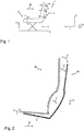
- FIG. 1 shows a vehicle seat 1 with a seat part 2 and a backrest 3.
- the seat 1 is parked and secured by means of a scissors-type frame 4 on a vehicle floor 5 of a vehicle not further shown.
- the vehicle seat 1 has a damping and / or a suspension (not shown here).
- the various arrows 6, 7, 8, 9, 10, 30 indicate the adjustment possibilities of the various seat configuration positions, namely the seat height position 6, the seat tilt position 7, the backrest tilt position 8, the lumbar support position 9, the longitudinal position 30 and the shoulder rest position 10.
- FIG. 2 1 shows the vehicle seat according to the invention in its first seating configuration 28, represented by the hatched area, shown here for an upright posture and a lumbar support configuration of the vehicle seat 1, and in its second seating configuration 29 represented by the solid black area, here for an inclined one Posture and shown as a kyphosis-supporting configuration of the vehicle seat 1.
- the second seat configuration 29 differs from the first seat configuration 28 as follows. Again FIG. 2 can be seen exactly, the seat tilt position 7 has been increased, which is associated with the fact that the inclination of the seat part 2 was increased relative to the horizontal.
- the first seating configuration 28 shows a lordosis-assisted adjustment of the lumbar support position 9
- the second seating configuration 29 shows a kyphosis-assisting adjustment of the lumbar support position 9.
- the longitudinal position 30 of the vehicle seat 1 has been changed.
- the longitudinal position 30 of the second seat configuration 29 is now more rearward in the vehicle seat longitudinal direction than in the first seat configuration 28.
- the seat height position 6 of the second seat configuration 29 has been reduced from the first seat configuration 28.
- the seat configuration positions 6, 7, 8, 9, 10, 30 are selected and changed so that the neck and head area of the driver continue to be relaxed forward, so as to continue to have optimal visibility of the road or the environment.
- the seat configuration positions 6, 7, 8, 9, 10, 30 are changed by the control device 17 so that the eye contact with the road or the environment is not interrupted.
- the Indian FIG. 3A shown vehicle seat 1 further comprises an armrest 11, on which various actuators 12, 13, 14 are arranged in the form of buttons for setting and storing the first and second seat configuration of the vehicle seat 1.
- various actuators 12, 13, 14 are arranged in the form of buttons for setting and storing the first and second seat configuration of the vehicle seat 1.
- a three such buttons 12, 13, 14 are provided, wherein the first button 12 stores the first seat configuration, the second button 13 stores the second seat configuration and the third button 14, the health function is activated or deactivated.
- other attachment areas for receiving the actuators are also conceivable are other attachment areas for receiving the actuators.
- the Indian FIG. 3B shown vehicle seat 1 has no such button attached to a seat component.
- a visual console 15 is arranged.
- This visual console 15 may be a touch pad 16 or the like, for example.
- Advantage of this arrangement is that can be displayed on the screen to the driver, as he a specific seating configuration, such as a first 28 and a second seat configuration 29, ie an upright and inclined attitude in the form of a lordosis or kyphosis-supporting configuration, has to adjust.
- a storing of these seat configurations 28, 29 takes place here preferably via an input on the touch pad 16.
- control device 17 can also be controlled by means of an app, so that permanently installed actuating elements 12, 13, 14 and display devices 15, 16 can be dispensed with.
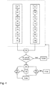
- the illustrated flow chart describes a possible method sequence which, in particular, motivates the driver during a journey to actively change his sitting position due to the change between the first 28 and second seat configuration 29.
- the first 28 and the second seat configuration 29 of the vehicle seat 1 are changed by changing the seat configuration positions 6, 7, 8, 9, 10, 30, ie the seat recline position 7, the reclining position 8, the seat height position 6, the lumbar position 9, the longitudinal position of the seat 30 and the shoulder rest position 10, set.
- the driver begins sequentially adjusting the respective seat configuration positions 6, 7, 8, 9, 10, 30, with a possible split such that parameter P1 is the seat recline position, P2 the reclining position, P3 the seat height position, P4 the lumbar position, P5 the shoulder post position and P6 is the longitudinal position of the vehicle seat.
- a different order of seat configuration position adjustment may be possible.
- the vehicle driver After successively setting the seat configuration positions P1 to P6, the vehicle driver operates the first button S1 and thus stores the setting as the first seat configuration 28 of the vehicle seat in the storage device 18 of the controller 17.
- the driver begins to readjust the seat configuration positions P1 to P6, so that a second seat configuration 29 of the vehicle seat 1 is given, which differs at least in one, advantageously in at least two of the positions and is particularly advantageous in at least three of the positions.
- the driver saves the second seat configuration 29 by operating the second button S2 as well as the first seat configuration 28 in the storage device 18 of the control device 17.
- the control device 17 issues an error message to the vehicle driver and advantageously prompts him to set and store the corresponding missing seat configuration or the missing seat configurations. If a first 28 as well as a second seat configuration 29 are located in the memory of the memory device 18, the control device 17 will set one of the two seat configurations by actuating the corresponding actuators 19. This is preferably the first seat configuration 28.
- an internal clock which is set to a certain time interval and is adjustable.
- a time interval can be about 10 minutes.
- the control device 17 preferably checks whether the health button is activated. If this is not the case because, for example, the driver has switched off the health function, the program is continued after the health button has been pressed again, ie the third button.
- the first seat configuration of the vehicle seat is adjusted again by a simultaneous adjustment of the positions.
- the control device 17 in this case comprises a memory device 18, in which the first 28 and the second seat configuration 29 of the vehicle seat 1 are stored.
- the control device 17 comprises a plurality of input channels I, which is connected to the three different buttons 12, 13, 14.
- the input channels I can be both analog nature or digital nature. Analog input channels I are formed, for example, when the buttons are actual buttons, digital input channels can be formed by pressing the buttons on a touch pads.
- the output channels O of the control device 17 are each connected to an actuator 19, by means of which the respective positions of the seat 1 can be adjusted.
- an output channel O is preferably connected to an actuator 19 in each case.
- each actuator 19 can be controlled separately, which is particularly advantageous for a simultaneous adjustment of the parameters by the actuators 19.
- the positions of the actuators 19 are given only by way of example.
- FIGS. 6A and 6B show by way of example various embodiments for changing the lordosis or kyphosis in the lumbar and / or chest.
- FIG. 6A shows a driven by an actuator 19, in particular a motor eccentric 20 and arranged in front sheet metal strip 21.
- the metal strips 21 are thereby seen oblong in seat width direction B, wherein a plurality of metal strips 21 are provided.
- the various metal strips 21 are connected to each other elastically by means of a connection 22, wherein seen in vehicle seat height direction H top and bottom sheet metal strip 21 at one end fixed to a backrest frame (not shown here) is connected.
- the eccentric 20 is not in operative contact with any of the metal strips 21, this is referred to as zero position. If the eccentric 20 is now operated in the zero position, then one end moves towards the metal strips 21, so that it comes into operative contact with this. If the eccentric 20 is rotated further, it presses this metal strip 21 seen in the vehicle longitudinal direction L forward, thereby by means of the elastic connection 22 between the metal strip 21, a forward curvature, ie a Lordoseunterstützung arises. Moves the eccentric 20 now away from the metal strip 21 away, so backwards, then move the metal strip 21 back to its zero position.
- FIG. 6B Similar works in the FIG. 6B shown embodiment.
- the sheet metal strip construction can be seen in vehicle seat width direction B.
- a deformation element 23 in the form of a rod 23 with a metal strip 21 in operative contact, particularly preferably the deformation element 23 with the metal strip 21 is fixed or detachably connected.
- the deformation element 23 is preferably displaceable in the vehicle longitudinal direction L by means of an actuator 19, such as a motor. Upon a displacement of the deformation element 23 in the vehicle longitudinal direction L forward, a curvature is also formed in the vehicle longitudinal direction L from the front, so a lordosis support is formed.
- the deformation element 23 is formed in seat width direction B, so that a uniform curvature over the entire vehicle seat width direction B is formed.
- the deformation element 23 in the region which is in operative contact with the sheet metal strip 21 in a curved shape, so that a particularly advantageous deformation of the sheet metal strip 21 can come about.
- a bracket member 24 is formed such that it is pivotable about the end portions 26.
- the extending in the vehicle seat width direction B transverse element 27 of the bracket member 24 is preferably in this case with one of the sheet metal strips 21 in operative contact or as well as the rod 23 with a metal strip 21 fixed or detachably connected.
- bracket member 24 By pivoting the bracket member 24 in the vehicle longitudinal direction L forward, as in FIG. 7B shown, the standing in operative contact with the bracket member 24 sheet metal strip 21 is moved forward. Since this is also advantageous elastically connected to the other metal strips 21, a beneficial lordosis-supporting curvature is achieved here.
- the metal strips 21 are arranged not extending in the vehicle seat width direction B, but in the vehicle seat height direction H.
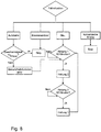
- FIG. 8 a further flowchart can be seen, which shows how a change of the seat configuration 28, 29 is influenced depending on external actuators, in particular in different driving modes.
- control device 17 By means of the control device 17, it is possible to determine the current driving situation.
- the respective value is received and processed by means of the control device 17 and evaluated even more advantageously over a relatively long period of time, for example as long as the engine is activated.
- the health function is preferably automatically activated or deactivated. For example, if it is a highway ride, for example, at a speed greater than 150 km / h, so it is advantageous for the driver to sit quietly and concentrated. The health function would be distracting. At lower speeds, however, the health function may be active as less attention is needed. Preferably, the limit speed be specified by the driver and entered into the control device.
- the control device detects a braking maneuver and thereby automatically deactivates the health function. After a predefinable or predetermined time difference, the health function is then automatically activated again. The time difference is calculated from the last braking maneuver and always reset and restarted when braking again.
- the seat configurations are set and the engine is activated. If the engine is deactivated, the health function is deactivated. An exception here can be the driving situation congestion.
- a change of the seat configurations is carried out every 10 minutes, ie if the first seat configuration has been set for 10 minutes, the second seat configuration is changed, after which the first seat configuration is changed again after 10 minutes.
- Posture 1 corresponds to the first seat configuration
- vGrenz corresponds to the specified or specifiable limit speed.
Landscapes
- Engineering & Computer Science (AREA)
- Aviation & Aerospace Engineering (AREA)
- Transportation (AREA)
- Mechanical Engineering (AREA)
- Human Computer Interaction (AREA)
- Seats For Vehicles (AREA)
Claims (8)
- Siège de véhicule (1) ayant une assise (2) et un dossier (3) et ayant des positions de configuration de siège modifiables (6, 7, 8, 9, 10, 30), comportant une première position d'un support d'épaule (10), une deuxième position d'un support lombaire (9), une troisième position de hauteur d'assise (6), une quatrième position longitudinale (30) du siège de véhicule (1), une cinquième position d'inclinaison d'assise (7) et une sixième position d'inclinaison de dossier (8), au moyen desquelles une première (28) et une seconde configuration de siège (29) différente de celle-ci sont aptes à être définies,
caractérisé par le fait que
les configurations de siège (28, 29) diffèrent dans au moins deux positions différentes (6, 7, 8, 9, 10, 30) et le siège de véhicule (1) présente un dispositif de commande (17) au moyen duquel la première (28) et la seconde configuration de siège (29) du siège de véhicule (1) sont réglables automatiquement en alternance après un intervalle de temps prédéfini et modifiable au moyen d'une modification simultanée et indépendante l'une de l'autre desdites au moins deux positions différentes (6, 7, 8, 9, 10, 30). - Siège de véhicule (1) selon la revendication 1,
caractérisé par le fait que
les configurations de siège (28, 29) diffèrent dans toutes les six positions de configuration de siège (6, 7, 8, 9, 10, 30). - Siège de véhicule (1) selon la revendication 1,
caractérisé par le fait que
dans au moins deux étapes de réglage successives, à chaque fois au moins deux des positions de configuration de siège (6, 7, 8, 9, 10, 30) sont réglables simultanément et indépendamment l'une de l'autre. - Siège de véhicule (1) selon l'une des revendications 1 à 3,
caractérisé par le fait que
au moyen du dispositif de commande (17) en alternance la première (28) et la seconde configuration de siège (29) sont réglables automatiquement. - Siège de véhicule (1) selon l'une des revendications 1 à 4,
caractérisé par le fait que
chacune des positions de configuration de siège (6, 7, 8, 9, 10, 30) est modifiable par au moins un actionneur (19), qui est relié fonctionnellement avec un élément appartenant au paramètre de configuration de siège respectif (6, 7, 8, 9, 10, 30). - Siège de véhicule (1) selon l'une des revendications 1 à 5,
caractérisé par le fait que
le dispositif de commande (17) comporte un dispositif de mémoire (18), dans lequel la première (28) et la seconde configuration de siège (29) sont mémorisables. - Siège de véhicule (1) selon l'une des revendications 1 à 6,
caractérisé par le fait qu'
un conducteur de véhicule assis sur le siège de véhicule (1) peut être invité, au moyen d'un signal acoustique et/ou optique, à effectuer un changement des configurations de siège (28, 29). - Procédé de réglage de configurations de siège (28, 29) d'un siège de véhicule (1) comportant une assise (2) et un dossier (3) et ayant des positions de configuration de siège (6, 7, 8, 9, 10, 30) modifiables, comportant une première position d'un support d'épaule (10), une deuxième position d'un support lombaire (9), une troisième position de hauteur d'assise (6), une quatrième position longitudinale (30) du siège de véhicule (1), une cinquième position d'inclinaison d'assise (7) et une sixième position d'inclinaison de dossier (8), au moyen desquelles une première (28) et une seconde configuration de siège (29) différente de celle-ci sont définies,
caractérisé par le fait que
les configurations de siège (28, 29) diffèrent dans au moins deux positions différentes (6, 7, 8, 9, 10, 30) et le siège de véhicule (1) présente un dispositif de commande (17) au moyen duquel la première (28) et la seconde configuration de siège (29) du siège de véhicule (1) sont réglées automatiquement en alternance après un intervalle de temps prédéfini et modifiable au moyen d'une modification simultanée et indépendante l'une de l'autre desdites au moins deux positions différentes (6, 7, 8, 9, 10, 30).
Applications Claiming Priority (1)
| Application Number | Priority Date | Filing Date | Title |
|---|---|---|---|
| DE102015102558 | 2015-02-23 |
Publications (2)
| Publication Number | Publication Date |
|---|---|
| EP3059116A1 EP3059116A1 (fr) | 2016-08-24 |
| EP3059116B1 true EP3059116B1 (fr) | 2019-10-23 |
Family
ID=55405228
Family Applications (1)
| Application Number | Title | Priority Date | Filing Date |
|---|---|---|---|
| EP16156702.9A Active EP3059116B1 (fr) | 2015-02-23 | 2016-02-22 | Siege ergonomique |
Country Status (2)
| Country | Link |
|---|---|
| EP (1) | EP3059116B1 (fr) |
| DE (1) | DE102016103017B4 (fr) |
Families Citing this family (7)
| Publication number | Priority date | Publication date | Assignee | Title |
|---|---|---|---|---|
| DE102017208388B4 (de) * | 2017-05-18 | 2022-12-08 | Ford Global Technologies, Llc | Verfahren zum Steuern eines Fahrzeugsitzes und Fahrzeug |
| DE102019102816B4 (de) | 2018-02-09 | 2024-05-16 | Adient Us Llc | Kopfstütze für einen Fahrzeugsitz eines Kraftfahrzeugs mit mindestens einem Fahrerassistenzsystem, Fahrzeugsitz, sowie Verfahren zum Überführen eines Fahrers aus einer Ruheposition in eine zur Fahrzeugführung geeignete Position |
| DE102018103036A1 (de) | 2018-02-12 | 2019-08-14 | Adient Engineering and IP GmbH | Kopfstütze für einen fahrzeugsitz eines kraftfahrzeugs mit mindestens einem fahrerassistenzsystem, sowie fahrzeugsitz |
| DE202018004991U1 (de) | 2018-10-26 | 2018-11-21 | Andreas Noll | Personensitz mit Sitzpositionsanpassung |
| DE102018221340A1 (de) * | 2018-12-10 | 2020-06-10 | Brose Fahrzeugteile SE & Co. Kommanditgesellschaft, Coburg | Konsole für ein Kraftfahrzeug |
| JP2021075188A (ja) * | 2019-11-11 | 2021-05-20 | 日本発條株式会社 | 車両用シート |
| DE102022101856A1 (de) | 2022-01-27 | 2023-07-27 | Bayerische Motoren Werke Aktiengesellschaft | Sitzvorrichtung für ein Kraftfahrzeug |
Family Cites Families (8)
| Publication number | Priority date | Publication date | Assignee | Title |
|---|---|---|---|---|
| JP2751431B2 (ja) * | 1989-07-14 | 1998-05-18 | 日産自動車株式会社 | シート |
| DE19522897C2 (de) * | 1995-06-23 | 1998-07-02 | Daimler Benz Ag | Einstellbarer Sitz, insbesondere in einem Fahrzeug |
| US6055473A (en) * | 1997-02-19 | 2000-04-25 | General Motors Corporation | Adaptive seating system |
| DE19747547A1 (de) * | 1997-10-28 | 1999-05-06 | Bosch Gmbh Robert | Sitz für ein Kraftfahrzeug |
| DE19938698A1 (de) * | 1999-08-14 | 2001-02-15 | Volkswagen Ag | Fahrzeugsitz |
| US7566096B2 (en) * | 2005-09-30 | 2009-07-28 | Innovative Biomechanical Solutions, Incorporated | Vehicle seating system and method for reducing fatigue |
| DE102007033306A1 (de) * | 2007-07-18 | 2009-01-22 | Neb, Alexander | Dynamischer Stabilisationssitz (DSS) |
| DE102010052409A1 (de) * | 2010-11-24 | 2012-05-24 | Daimler Ag | Verfahren und Vorrichtung zur Unterstützung eines Fahrzeugführers |
-
2016
- 2016-02-22 EP EP16156702.9A patent/EP3059116B1/fr active Active
- 2016-02-22 DE DE102016103017.1A patent/DE102016103017B4/de active Active
Non-Patent Citations (1)
| Title |
|---|
| None * |
Also Published As
| Publication number | Publication date |
|---|---|
| DE102016103017B4 (de) | 2021-03-04 |
| DE102016103017A1 (de) | 2016-08-25 |
| EP3059116A1 (fr) | 2016-08-24 |
Similar Documents
| Publication | Publication Date | Title |
|---|---|---|
| EP3059116B1 (fr) | Siege ergonomique | |
| DE4022423C2 (de) | Sitz mit Einrichtung zum Verhindern von Ermüdung | |
| EP2207698B1 (fr) | Procédé et dispositif de réglage d'un siège | |
| DE102017122474B4 (de) | Fahrzeugwecksystem | |
| DE19828254C2 (de) | Sitz- und/oder Liegevorrichtung, insbesondere Fahr- oder Flugzeugsitz | |
| DE102017206313B4 (de) | Verfahren zur Sitzverstellung eines Verkehrsmittels | |
| DE102016100325A1 (de) | Flexibler Fahrzeugsitz | |
| EP1712405B1 (fr) | Siège, en particulier siège de véhicule | |
| EP3052338A1 (fr) | Procédé de préréglage d'un siège de véhicule | |
| DE102017201871A1 (de) | Einstellbare Sitzanordnung und Fahrzeuganordnung | |
| DE102017208388B4 (de) | Verfahren zum Steuern eines Fahrzeugsitzes und Fahrzeug | |
| DE102017205135A1 (de) | Steuervorrichtung in einem Fahrzeug zum Ansteuern einer eine Komfortfunktion bereitstellenden Einheit | |
| DE102006061502A1 (de) | Sitz für ein Kraftfahrzeug, Kraftfahrzeug mit mindestens einem Sitz und Verfahren zum automatisierten Einstellen eines Sitzes | |
| DE102020209870A1 (de) | Oszillierender fahrzeugsitz für insassenkomfort | |
| DE102011010210A1 (de) | Sitzanordnung und Verfahren zum Betreiben einer Sitzanordnung, insbesondere für einen Kraftwagen | |
| DE102018220465A1 (de) | Verfahren zur Anpassung von verstellbaren Komponenten in einem Kraftfahrzeug an eine Statur einer Person | |
| EP0932519B1 (fr) | Procédé d'ajustement d'un composant de siège de véhicules | |
| DE102019102816B4 (de) | Kopfstütze für einen Fahrzeugsitz eines Kraftfahrzeugs mit mindestens einem Fahrerassistenzsystem, Fahrzeugsitz, sowie Verfahren zum Überführen eines Fahrers aus einer Ruheposition in eine zur Fahrzeugführung geeignete Position | |
| WO2008028604A1 (fr) | Unité de manœuvre pour au moins un dispositif de réglage d'un siège de véhicule | |
| EP1564066B1 (fr) | Siège | |
| DE10336316B4 (de) | Sitz, insbesondere Kraftfahrzeugsitz | |
| DE102018000317A1 (de) | Verfahren zum Verstellen eines Kraftwagensitzes und Kraftwagensitz | |
| DE10241250B4 (de) | Sitzeinrichtung | |
| DE10010989A1 (de) | Verfahren zur Ermittlung einer geeigneten Position einer Kopf- und/oder Nackenstütze | |
| DE102021204802A1 (de) | Fahrzeugsitz, Kraftfahrzeug und Verfahren zum Steuern eines Fahrzeugsitzes |
Legal Events
| Date | Code | Title | Description |
|---|---|---|---|
| PUAI | Public reference made under article 153(3) epc to a published international application that has entered the european phase |
Free format text: ORIGINAL CODE: 0009012 |
|
| AK | Designated contracting states |
Kind code of ref document: A1 Designated state(s): AL AT BE BG CH CY CZ DE DK EE ES FI FR GB GR HR HU IE IS IT LI LT LU LV MC MK MT NL NO PL PT RO RS SE SI SK SM TR |
|
| AX | Request for extension of the european patent |
Extension state: BA ME |
|
| RIN1 | Information on inventor provided before grant (corrected) |
Inventor name: SONNLEITNER, TOBIAS Inventor name: DEMLEITNER, BERTHOLD Inventor name: DELLING, GERHARD Inventor name: BUEHLMEYER, KATJA |
|
| 17P | Request for examination filed |
Effective date: 20160915 |
|
| RBV | Designated contracting states (corrected) |
Designated state(s): AL AT BE BG CH CY CZ DE DK EE ES FI FR GB GR HR HU IE IS IT LI LT LU LV MC MK MT NL NO PL PT RO RS SE SI SK SM TR |
|
| REG | Reference to a national code |
Ref country code: DE Ref legal event code: R079 Ref document number: 502016007179 Country of ref document: DE Free format text: PREVIOUS MAIN CLASS: B60N0002020000 Ipc: B60N0002900000 |
|
| RIC1 | Information provided on ipc code assigned before grant |
Ipc: B60N 2/16 20060101ALI20180903BHEP Ipc: B60N 2/02 20060101ALI20180903BHEP Ipc: B60N 2/66 20060101ALI20180903BHEP Ipc: B60N 2/06 20060101ALI20180903BHEP Ipc: B60N 2/24 20060101ALI20180903BHEP Ipc: B60N 2/80 20180101ALI20180903BHEP Ipc: B60N 2/90 20180101AFI20180903BHEP Ipc: B60N 2/10 20060101ALI20180903BHEP Ipc: B60N 2/75 20180101ALI20180903BHEP Ipc: B60N 2/22 20060101ALI20180903BHEP |
|
| STAA | Information on the status of an ep patent application or granted ep patent |
Free format text: STATUS: EXAMINATION IS IN PROGRESS |
|
| 17Q | First examination report despatched |
Effective date: 20181025 |
|
| RIC1 | Information provided on ipc code assigned before grant |
Ipc: B60N 2/02 20060101ALI20180903BHEP Ipc: B60N 2/06 20060101ALI20180903BHEP Ipc: B60N 2/90 20180101AFI20180903BHEP Ipc: B60N 2/80 20180101ALI20180903BHEP Ipc: B60N 2/10 20060101ALI20180903BHEP Ipc: B60N 2/66 20060101ALI20180903BHEP Ipc: B60N 2/22 20060101ALI20180903BHEP Ipc: B60N 2/24 20060101ALI20180903BHEP Ipc: B60N 2/75 20180101ALI20180903BHEP Ipc: B60N 2/16 20060101ALI20180903BHEP |
|
| GRAP | Despatch of communication of intention to grant a patent |
Free format text: ORIGINAL CODE: EPIDOSNIGR1 |
|
| STAA | Information on the status of an ep patent application or granted ep patent |
Free format text: STATUS: GRANT OF PATENT IS INTENDED |
|
| INTG | Intention to grant announced |
Effective date: 20190612 |
|
| GRAS | Grant fee paid |
Free format text: ORIGINAL CODE: EPIDOSNIGR3 |
|
| GRAA | (expected) grant |
Free format text: ORIGINAL CODE: 0009210 |
|
| STAA | Information on the status of an ep patent application or granted ep patent |
Free format text: STATUS: THE PATENT HAS BEEN GRANTED |
|
| AK | Designated contracting states |
Kind code of ref document: B1 Designated state(s): AL AT BE BG CH CY CZ DE DK EE ES FI FR GB GR HR HU IE IS IT LI LT LU LV MC MK MT NL NO PL PT RO RS SE SI SK SM TR |
|
| REG | Reference to a national code |
Ref country code: GB Ref legal event code: FG4D Free format text: NOT ENGLISH |
|
| RIN1 | Information on inventor provided before grant (corrected) |
Inventor name: DELLING, GERHARD Inventor name: SONNLEITNER, TOBIAS Inventor name: BUEHLMEYER, KATJA Inventor name: DEMLEITNER, BERTHOLD |
|
| REG | Reference to a national code |
Ref country code: CH Ref legal event code: EP |
|
| REG | Reference to a national code |
Ref country code: IE Ref legal event code: FG4D Free format text: LANGUAGE OF EP DOCUMENT: GERMAN |
|
| REG | Reference to a national code |
Ref country code: DE Ref legal event code: R096 Ref document number: 502016007179 Country of ref document: DE |
|
| REG | Reference to a national code |
Ref country code: AT Ref legal event code: REF Ref document number: 1193279 Country of ref document: AT Kind code of ref document: T Effective date: 20191115 |
|
| REG | Reference to a national code |
Ref country code: NL Ref legal event code: MP Effective date: 20191023 |
|
| REG | Reference to a national code |
Ref country code: LT Ref legal event code: MG4D |
|
| PG25 | Lapsed in a contracting state [announced via postgrant information from national office to epo] |
Ref country code: PL Free format text: LAPSE BECAUSE OF FAILURE TO SUBMIT A TRANSLATION OF THE DESCRIPTION OR TO PAY THE FEE WITHIN THE PRESCRIBED TIME-LIMIT Effective date: 20191023 Ref country code: NO Free format text: LAPSE BECAUSE OF FAILURE TO SUBMIT A TRANSLATION OF THE DESCRIPTION OR TO PAY THE FEE WITHIN THE PRESCRIBED TIME-LIMIT Effective date: 20200123 Ref country code: SE Free format text: LAPSE BECAUSE OF FAILURE TO SUBMIT A TRANSLATION OF THE DESCRIPTION OR TO PAY THE FEE WITHIN THE PRESCRIBED TIME-LIMIT Effective date: 20191023 Ref country code: LV Free format text: LAPSE BECAUSE OF FAILURE TO SUBMIT A TRANSLATION OF THE DESCRIPTION OR TO PAY THE FEE WITHIN THE PRESCRIBED TIME-LIMIT Effective date: 20191023 Ref country code: FI Free format text: LAPSE BECAUSE OF FAILURE TO SUBMIT A TRANSLATION OF THE DESCRIPTION OR TO PAY THE FEE WITHIN THE PRESCRIBED TIME-LIMIT Effective date: 20191023 Ref country code: PT Free format text: LAPSE BECAUSE OF FAILURE TO SUBMIT A TRANSLATION OF THE DESCRIPTION OR TO PAY THE FEE WITHIN THE PRESCRIBED TIME-LIMIT Effective date: 20200224 Ref country code: GR Free format text: LAPSE BECAUSE OF FAILURE TO SUBMIT A TRANSLATION OF THE DESCRIPTION OR TO PAY THE FEE WITHIN THE PRESCRIBED TIME-LIMIT Effective date: 20200124 Ref country code: BG Free format text: LAPSE BECAUSE OF FAILURE TO SUBMIT A TRANSLATION OF THE DESCRIPTION OR TO PAY THE FEE WITHIN THE PRESCRIBED TIME-LIMIT Effective date: 20200123 Ref country code: LT Free format text: LAPSE BECAUSE OF FAILURE TO SUBMIT A TRANSLATION OF THE DESCRIPTION OR TO PAY THE FEE WITHIN THE PRESCRIBED TIME-LIMIT Effective date: 20191023 Ref country code: NL Free format text: LAPSE BECAUSE OF FAILURE TO SUBMIT A TRANSLATION OF THE DESCRIPTION OR TO PAY THE FEE WITHIN THE PRESCRIBED TIME-LIMIT Effective date: 20191023 |
|
| PG25 | Lapsed in a contracting state [announced via postgrant information from national office to epo] |
Ref country code: RS Free format text: LAPSE BECAUSE OF FAILURE TO SUBMIT A TRANSLATION OF THE DESCRIPTION OR TO PAY THE FEE WITHIN THE PRESCRIBED TIME-LIMIT Effective date: 20191023 Ref country code: HR Free format text: LAPSE BECAUSE OF FAILURE TO SUBMIT A TRANSLATION OF THE DESCRIPTION OR TO PAY THE FEE WITHIN THE PRESCRIBED TIME-LIMIT Effective date: 20191023 Ref country code: IS Free format text: LAPSE BECAUSE OF FAILURE TO SUBMIT A TRANSLATION OF THE DESCRIPTION OR TO PAY THE FEE WITHIN THE PRESCRIBED TIME-LIMIT Effective date: 20200224 |
|
| PG25 | Lapsed in a contracting state [announced via postgrant information from national office to epo] |
Ref country code: AL Free format text: LAPSE BECAUSE OF FAILURE TO SUBMIT A TRANSLATION OF THE DESCRIPTION OR TO PAY THE FEE WITHIN THE PRESCRIBED TIME-LIMIT Effective date: 20191023 |
|
| REG | Reference to a national code |
Ref country code: DE Ref legal event code: R097 Ref document number: 502016007179 Country of ref document: DE |
|
| PG2D | Information on lapse in contracting state deleted |
Ref country code: IS |
|
| PG25 | Lapsed in a contracting state [announced via postgrant information from national office to epo] |
Ref country code: RO Free format text: LAPSE BECAUSE OF FAILURE TO SUBMIT A TRANSLATION OF THE DESCRIPTION OR TO PAY THE FEE WITHIN THE PRESCRIBED TIME-LIMIT Effective date: 20191023 Ref country code: CZ Free format text: LAPSE BECAUSE OF FAILURE TO SUBMIT A TRANSLATION OF THE DESCRIPTION OR TO PAY THE FEE WITHIN THE PRESCRIBED TIME-LIMIT Effective date: 20191023 Ref country code: EE Free format text: LAPSE BECAUSE OF FAILURE TO SUBMIT A TRANSLATION OF THE DESCRIPTION OR TO PAY THE FEE WITHIN THE PRESCRIBED TIME-LIMIT Effective date: 20191023 Ref country code: DK Free format text: LAPSE BECAUSE OF FAILURE TO SUBMIT A TRANSLATION OF THE DESCRIPTION OR TO PAY THE FEE WITHIN THE PRESCRIBED TIME-LIMIT Effective date: 20191023 Ref country code: ES Free format text: LAPSE BECAUSE OF FAILURE TO SUBMIT A TRANSLATION OF THE DESCRIPTION OR TO PAY THE FEE WITHIN THE PRESCRIBED TIME-LIMIT Effective date: 20191023 Ref country code: IS Free format text: LAPSE BECAUSE OF FAILURE TO SUBMIT A TRANSLATION OF THE DESCRIPTION OR TO PAY THE FEE WITHIN THE PRESCRIBED TIME-LIMIT Effective date: 20200223 |
|
| PLBE | No opposition filed within time limit |
Free format text: ORIGINAL CODE: 0009261 |
|
| STAA | Information on the status of an ep patent application or granted ep patent |
Free format text: STATUS: NO OPPOSITION FILED WITHIN TIME LIMIT |
|
| PG25 | Lapsed in a contracting state [announced via postgrant information from national office to epo] |
Ref country code: SK Free format text: LAPSE BECAUSE OF FAILURE TO SUBMIT A TRANSLATION OF THE DESCRIPTION OR TO PAY THE FEE WITHIN THE PRESCRIBED TIME-LIMIT Effective date: 20191023 Ref country code: SM Free format text: LAPSE BECAUSE OF FAILURE TO SUBMIT A TRANSLATION OF THE DESCRIPTION OR TO PAY THE FEE WITHIN THE PRESCRIBED TIME-LIMIT Effective date: 20191023 |
|
| 26N | No opposition filed |
Effective date: 20200724 |
|
| REG | Reference to a national code |
Ref country code: CH Ref legal event code: PL |
|
| GBPC | Gb: european patent ceased through non-payment of renewal fee |
Effective date: 20200222 |
|
| REG | Reference to a national code |
Ref country code: BE Ref legal event code: MM Effective date: 20200229 |
|
| PG25 | Lapsed in a contracting state [announced via postgrant information from national office to epo] |
Ref country code: MC Free format text: LAPSE BECAUSE OF FAILURE TO SUBMIT A TRANSLATION OF THE DESCRIPTION OR TO PAY THE FEE WITHIN THE PRESCRIBED TIME-LIMIT Effective date: 20191023 Ref country code: LU Free format text: LAPSE BECAUSE OF NON-PAYMENT OF DUE FEES Effective date: 20200222 |
|
| PG25 | Lapsed in a contracting state [announced via postgrant information from national office to epo] |
Ref country code: LI Free format text: LAPSE BECAUSE OF NON-PAYMENT OF DUE FEES Effective date: 20200229 Ref country code: CH Free format text: LAPSE BECAUSE OF NON-PAYMENT OF DUE FEES Effective date: 20200229 Ref country code: SI Free format text: LAPSE BECAUSE OF FAILURE TO SUBMIT A TRANSLATION OF THE DESCRIPTION OR TO PAY THE FEE WITHIN THE PRESCRIBED TIME-LIMIT Effective date: 20191023 |
|
| PG25 | Lapsed in a contracting state [announced via postgrant information from national office to epo] |
Ref country code: GB Free format text: LAPSE BECAUSE OF NON-PAYMENT OF DUE FEES Effective date: 20200222 Ref country code: IE Free format text: LAPSE BECAUSE OF NON-PAYMENT OF DUE FEES Effective date: 20200222 |
|
| PG25 | Lapsed in a contracting state [announced via postgrant information from national office to epo] |
Ref country code: BE Free format text: LAPSE BECAUSE OF NON-PAYMENT OF DUE FEES Effective date: 20200229 |
|
| REG | Reference to a national code |
Ref country code: AT Ref legal event code: MM01 Ref document number: 1193279 Country of ref document: AT Kind code of ref document: T Effective date: 20210222 |
|
| PG25 | Lapsed in a contracting state [announced via postgrant information from national office to epo] |
Ref country code: AT Free format text: LAPSE BECAUSE OF NON-PAYMENT OF DUE FEES Effective date: 20210222 |
|
| PG25 | Lapsed in a contracting state [announced via postgrant information from national office to epo] |
Ref country code: TR Free format text: LAPSE BECAUSE OF FAILURE TO SUBMIT A TRANSLATION OF THE DESCRIPTION OR TO PAY THE FEE WITHIN THE PRESCRIBED TIME-LIMIT Effective date: 20191023 Ref country code: MT Free format text: LAPSE BECAUSE OF FAILURE TO SUBMIT A TRANSLATION OF THE DESCRIPTION OR TO PAY THE FEE WITHIN THE PRESCRIBED TIME-LIMIT Effective date: 20191023 Ref country code: CY Free format text: LAPSE BECAUSE OF FAILURE TO SUBMIT A TRANSLATION OF THE DESCRIPTION OR TO PAY THE FEE WITHIN THE PRESCRIBED TIME-LIMIT Effective date: 20191023 |
|
| PG25 | Lapsed in a contracting state [announced via postgrant information from national office to epo] |
Ref country code: MK Free format text: LAPSE BECAUSE OF FAILURE TO SUBMIT A TRANSLATION OF THE DESCRIPTION OR TO PAY THE FEE WITHIN THE PRESCRIBED TIME-LIMIT Effective date: 20191023 |
|
| PGFP | Annual fee paid to national office [announced via postgrant information from national office to epo] |
Ref country code: FR Payment date: 20230217 Year of fee payment: 8 |
|
| PGFP | Annual fee paid to national office [announced via postgrant information from national office to epo] |
Ref country code: IT Payment date: 20230228 Year of fee payment: 8 |
|
| PGFP | Annual fee paid to national office [announced via postgrant information from national office to epo] |
Ref country code: DE Payment date: 20240216 Year of fee payment: 9 |