EP3057630B1 - Injection device for delivery of a liquid medicament with medicament container displacement - Google Patents
Injection device for delivery of a liquid medicament with medicament container displacement Download PDFInfo
- Publication number
- EP3057630B1 EP3057630B1 EP14784471.6A EP14784471A EP3057630B1 EP 3057630 B1 EP3057630 B1 EP 3057630B1 EP 14784471 A EP14784471 A EP 14784471A EP 3057630 B1 EP3057630 B1 EP 3057630B1
- Authority
- EP
- European Patent Office
- Prior art keywords
- reservoir
- needle
- medicament
- pressure container
- injection device
- Prior art date
- Legal status (The legal status is an assumption and is not a legal conclusion. Google has not performed a legal analysis and makes no representation as to the accuracy of the status listed.)
- Active
Links
- 239000003814 drug Substances 0.000 title claims description 188
- 239000007924 injection Substances 0.000 title claims description 177
- 238000002347 injection Methods 0.000 title claims description 177
- 238000006073 displacement reaction Methods 0.000 title claims description 101
- 239000007788 liquid Substances 0.000 title claims description 27
- 239000012530 fluid Substances 0.000 claims description 114
- 238000004891 communication Methods 0.000 claims description 37
- 230000009471 action Effects 0.000 claims description 14
- 230000000694 effects Effects 0.000 claims description 10
- JUFFVKRROAPVBI-PVOYSMBESA-N chembl1210015 Chemical compound C([C@@H](C(=O)N[C@@H]([C@@H](C)CC)C(=O)N[C@@H](CCC(O)=O)C(=O)N[C@@H](CC=1C2=CC=CC=C2NC=1)C(=O)N[C@@H](CC(C)C)C(=O)N[C@@H](CCCCN)C(=O)N[C@@H](CC(=O)N[C@H]1[C@@H]([C@@H](O)[C@H](O[C@H]2[C@@H]([C@@H](O)[C@@H](O)[C@@H](CO[C@]3(O[C@@H](C[C@H](O)[C@H](O)CO)[C@H](NC(C)=O)[C@@H](O)C3)C(O)=O)O2)O)[C@@H](CO)O1)NC(C)=O)C(=O)NCC(=O)NCC(=O)N1[C@@H](CCC1)C(=O)N[C@@H](CO)C(=O)N[C@@H](CO)C(=O)NCC(=O)N[C@@H](C)C(=O)N1[C@@H](CCC1)C(=O)N1[C@@H](CCC1)C(=O)N1[C@@H](CCC1)C(=O)N[C@@H](CO)C(N)=O)NC(=O)[C@H](CC(C)C)NC(=O)[C@H](CCCNC(N)=N)NC(=O)[C@@H](NC(=O)[C@H](C)NC(=O)[C@H](CCC(O)=O)NC(=O)[C@H](CCC(O)=O)NC(=O)[C@H](CCC(O)=O)NC(=O)[C@H](CCSC)NC(=O)[C@H](CCC(N)=O)NC(=O)[C@H](CCCCN)NC(=O)[C@H](CO)NC(=O)[C@H](CC(C)C)NC(=O)[C@H](CC(O)=O)NC(=O)[C@H](CO)NC(=O)[C@@H](NC(=O)[C@H](CC=1C=CC=CC=1)NC(=O)[C@@H](NC(=O)CNC(=O)[C@H](CCC(O)=O)NC(=O)CNC(=O)[C@@H](N)CC=1NC=NC=1)[C@@H](C)O)[C@@H](C)O)C(C)C)C1=CC=CC=C1 JUFFVKRROAPVBI-PVOYSMBESA-N 0.000 description 54
- 239000002585 base Substances 0.000 description 52
- 108010011459 Exenatide Proteins 0.000 description 50
- 229960001519 exenatide Drugs 0.000 description 50
- 101000976075 Homo sapiens Insulin Proteins 0.000 description 22
- QEFRNWWLZKMPFJ-YGVKFDHGSA-N L-methionine S-oxide Chemical compound CS(=O)CC[C@H](N)C(O)=O QEFRNWWLZKMPFJ-YGVKFDHGSA-N 0.000 description 22
- 238000000034 method Methods 0.000 description 22
- 239000007789 gas Substances 0.000 description 21
- PBGKTOXHQIOBKM-FHFVDXKLSA-N insulin (human) Chemical compound C([C@@H](C(=O)N[C@@H](CC(C)C)C(=O)N[C@H]1CSSC[C@H]2C(=O)N[C@H](C(=O)N[C@@H](CO)C(=O)N[C@H](C(=O)N[C@H](C(N[C@@H](CO)C(=O)N[C@@H](CC(C)C)C(=O)N[C@@H](CC=3C=CC(O)=CC=3)C(=O)N[C@@H](CCC(N)=O)C(=O)N[C@@H](CC(C)C)C(=O)N[C@@H](CCC(O)=O)C(=O)N[C@@H](CC(N)=O)C(=O)N[C@@H](CC=3C=CC(O)=CC=3)C(=O)N[C@@H](CSSC[C@H](NC(=O)[C@H](C(C)C)NC(=O)[C@H](CC(C)C)NC(=O)[C@H](CC=3C=CC(O)=CC=3)NC(=O)[C@H](CC(C)C)NC(=O)[C@H](C)NC(=O)[C@H](CCC(O)=O)NC(=O)[C@H](C(C)C)NC(=O)[C@H](CC(C)C)NC(=O)[C@H](CC=3NC=NC=3)NC(=O)[C@H](CO)NC(=O)CNC1=O)C(=O)NCC(=O)N[C@@H](CCC(O)=O)C(=O)N[C@@H](CCCNC(N)=N)C(=O)NCC(=O)N[C@@H](CC=1C=CC=CC=1)C(=O)N[C@@H](CC=1C=CC=CC=1)C(=O)N[C@@H](CC=1C=CC(O)=CC=1)C(=O)N[C@@H]([C@@H](C)O)C(=O)N1[C@@H](CCC1)C(=O)N[C@@H](CCCCN)C(=O)N[C@@H]([C@@H](C)O)C(O)=O)C(=O)N[C@@H](CC(N)=O)C(O)=O)=O)CSSC[C@@H](C(N2)=O)NC(=O)[C@H](CCC(N)=O)NC(=O)[C@H](CCC(O)=O)NC(=O)[C@H](C(C)C)NC(=O)[C@@H](NC(=O)CN)[C@@H](C)CC)[C@@H](C)CC)[C@@H](C)O)NC(=O)[C@H](CCC(N)=O)NC(=O)[C@H](CC(N)=O)NC(=O)[C@@H](NC(=O)[C@@H](N)CC=1C=CC=CC=1)C(C)C)C1=CN=CN1 PBGKTOXHQIOBKM-FHFVDXKLSA-N 0.000 description 21
- 230000008878 coupling Effects 0.000 description 12
- 238000010168 coupling process Methods 0.000 description 12
- 238000005859 coupling reaction Methods 0.000 description 12
- 238000012377 drug delivery Methods 0.000 description 10
- 239000012634 fragment Substances 0.000 description 10
- 230000004941 influx Effects 0.000 description 10
- 230000008569 process Effects 0.000 description 10
- 238000007789 sealing Methods 0.000 description 10
- 235000001014 amino acid Nutrition 0.000 description 9
- 150000001413 amino acids Chemical class 0.000 description 9
- 238000005452 bending Methods 0.000 description 9
- 239000011888 foil Substances 0.000 description 8
- 150000003839 salts Chemical class 0.000 description 8
- 239000000427 antigen Substances 0.000 description 7
- 102000036639 antigens Human genes 0.000 description 7
- 108091007433 antigens Proteins 0.000 description 7
- 150000001875 compounds Chemical class 0.000 description 7
- 230000001681 protective effect Effects 0.000 description 7
- 230000008901 benefit Effects 0.000 description 5
- 238000013461 design Methods 0.000 description 5
- 229940079593 drug Drugs 0.000 description 5
- 230000006870 function Effects 0.000 description 5
- 230000001965 increasing effect Effects 0.000 description 5
- 108090000765 processed proteins & peptides Proteins 0.000 description 5
- LCGLNKUTAGEVQW-UHFFFAOYSA-N Dimethyl ether Chemical compound COC LCGLNKUTAGEVQW-UHFFFAOYSA-N 0.000 description 4
- 108060003951 Immunoglobulin Proteins 0.000 description 4
- ATUOYWHBWRKTHZ-UHFFFAOYSA-N Propane Chemical compound CCC ATUOYWHBWRKTHZ-UHFFFAOYSA-N 0.000 description 4
- 230000004913 activation Effects 0.000 description 4
- 206010012601 diabetes mellitus Diseases 0.000 description 4
- 238000010586 diagram Methods 0.000 description 4
- 102000018358 immunoglobulin Human genes 0.000 description 4
- 238000004519 manufacturing process Methods 0.000 description 4
- 230000000630 rising effect Effects 0.000 description 4
- 230000001960 triggered effect Effects 0.000 description 4
- 108010047041 Complementarity Determining Regions Proteins 0.000 description 3
- 238000013459 approach Methods 0.000 description 3
- 210000003719 b-lymphocyte Anatomy 0.000 description 3
- 230000000903 blocking effect Effects 0.000 description 3
- 238000004146 energy storage Methods 0.000 description 3
- 150000004676 glycans Chemical class 0.000 description 3
- 229940088597 hormone Drugs 0.000 description 3
- 239000005556 hormone Substances 0.000 description 3
- NOESYZHRGYRDHS-UHFFFAOYSA-N insulin Chemical class N1C(=O)C(NC(=O)C(CCC(N)=O)NC(=O)C(CCC(O)=O)NC(=O)C(C(C)C)NC(=O)C(NC(=O)CN)C(C)CC)CSSCC(C(NC(CO)C(=O)NC(CC(C)C)C(=O)NC(CC=2C=CC(O)=CC=2)C(=O)NC(CCC(N)=O)C(=O)NC(CC(C)C)C(=O)NC(CCC(O)=O)C(=O)NC(CC(N)=O)C(=O)NC(CC=2C=CC(O)=CC=2)C(=O)NC(CSSCC(NC(=O)C(C(C)C)NC(=O)C(CC(C)C)NC(=O)C(CC=2C=CC(O)=CC=2)NC(=O)C(CC(C)C)NC(=O)C(C)NC(=O)C(CCC(O)=O)NC(=O)C(C(C)C)NC(=O)C(CC(C)C)NC(=O)C(CC=2NC=NC=2)NC(=O)C(CO)NC(=O)CNC2=O)C(=O)NCC(=O)NC(CCC(O)=O)C(=O)NC(CCCNC(N)=N)C(=O)NCC(=O)NC(CC=3C=CC=CC=3)C(=O)NC(CC=3C=CC=CC=3)C(=O)NC(CC=3C=CC(O)=CC=3)C(=O)NC(C(C)O)C(=O)N3C(CCC3)C(=O)NC(CCCCN)C(=O)NC(C)C(O)=O)C(=O)NC(CC(N)=O)C(O)=O)=O)NC(=O)C(C(C)CC)NC(=O)C(CO)NC(=O)C(C(C)O)NC(=O)C1CSSCC2NC(=O)C(CC(C)C)NC(=O)C(NC(=O)C(CCC(N)=O)NC(=O)C(CC(N)=O)NC(=O)C(NC(=O)C(N)CC=1C=CC=CC=1)C(C)C)CC1=CN=CN1 NOESYZHRGYRDHS-UHFFFAOYSA-N 0.000 description 3
- 239000003055 low molecular weight heparin Substances 0.000 description 3
- 229940127215 low-molecular weight heparin Drugs 0.000 description 3
- 239000000203 mixture Substances 0.000 description 3
- 239000004033 plastic Substances 0.000 description 3
- 229920003023 plastic Polymers 0.000 description 3
- 229920001282 polysaccharide Polymers 0.000 description 3
- 239000005017 polysaccharide Substances 0.000 description 3
- 239000003380 propellant Substances 0.000 description 3
- 239000000126 substance Substances 0.000 description 3
- 238000012546 transfer Methods 0.000 description 3
- 230000000007 visual effect Effects 0.000 description 3
- 208000004476 Acute Coronary Syndrome Diseases 0.000 description 2
- 208000002249 Diabetes Complications Diseases 0.000 description 2
- 206010012689 Diabetic retinopathy Diseases 0.000 description 2
- 108010088406 Glucagon-Like Peptides Proteins 0.000 description 2
- 241000124008 Mammalia Species 0.000 description 2
- 239000002253 acid Substances 0.000 description 2
- 150000001447 alkali salts Chemical class 0.000 description 2
- 239000001273 butane Substances 0.000 description 2
- 125000000151 cysteine group Chemical group N[C@@H](CS)C(=O)* 0.000 description 2
- 230000006378 damage Effects 0.000 description 2
- 230000029087 digestion Effects 0.000 description 2
- LMHMJYMCGJNXRS-IOPUOMRJSA-N exendin-3 Chemical compound C([C@@H](C(=O)N[C@@H]([C@@H](C)CC)C(=O)N[C@@H](CCC(O)=O)C(=O)N[C@@H](CC=1C2=CC=CC=C2NC=1)C(=O)N[C@@H](CC(C)C)C(=O)N[C@@H](CCCCN)C(=O)N[C@@H](CC(N)=O)C(=O)NCC(=O)NCC(=O)N1[C@@H](CCC1)C(=O)N[C@@H](CO)C(=O)N[C@@H](CO)C(=O)NCC(=O)N[C@@H](C)C(=O)N1[C@@H](CCC1)C(=O)N1[C@@H](CCC1)C(=O)N1[C@@H](CCC1)C(=O)N[C@@H](CO)C(N)=O)NC(=O)[C@H](CC(C)C)NC(=O)[C@H](CCCNC(N)=N)NC(=O)[C@@H](NC(=O)[C@H](C)NC(=O)[C@H](CCC(O)=O)NC(=O)[C@H](CCC(O)=O)NC(=O)[C@H](CCC(O)=O)NC(=O)[C@H](CCSC)NC(=O)[C@H](CCC(N)=O)NC(=O)[C@H](CCCCN)NC(=O)[C@H](CO)NC(=O)[C@H](CC(C)C)NC(=O)[C@H](CC(O)=O)NC(=O)[C@H](CO)NC(=O)[C@@H](NC(=O)[C@H](CC=1C=CC=CC=1)NC(=O)[C@@H](NC(=O)CNC(=O)[C@H](CC(O)=O)NC(=O)[C@H](CO)NC(=O)[C@@H](N)CC=1N=CNC=1)[C@H](C)O)[C@H](C)O)C(C)C)C1=CC=CC=C1 LMHMJYMCGJNXRS-IOPUOMRJSA-N 0.000 description 2
- 230000003993 interaction Effects 0.000 description 2
- 230000007246 mechanism Effects 0.000 description 2
- 239000012528 membrane Substances 0.000 description 2
- 239000002991 molded plastic Substances 0.000 description 2
- 239000000178 monomer Substances 0.000 description 2
- IJDNQMDRQITEOD-UHFFFAOYSA-N n-butane Chemical compound CCCC IJDNQMDRQITEOD-UHFFFAOYSA-N 0.000 description 2
- OFBQJSOFQDEBGM-UHFFFAOYSA-N n-pentane Natural products CCCCC OFBQJSOFQDEBGM-UHFFFAOYSA-N 0.000 description 2
- -1 polypropylene Polymers 0.000 description 2
- 230000002028 premature Effects 0.000 description 2
- 102000004196 processed proteins & peptides Human genes 0.000 description 2
- 239000001294 propane Substances 0.000 description 2
- 238000011321 prophylaxis Methods 0.000 description 2
- 230000004044 response Effects 0.000 description 2
- 239000012453 solvate Substances 0.000 description 2
- 238000002560 therapeutic procedure Methods 0.000 description 2
- 238000011282 treatment Methods 0.000 description 2
- KIUKXJAPPMFGSW-DNGZLQJQSA-N (2S,3S,4S,5R,6R)-6-[(2S,3R,4R,5S,6R)-3-Acetamido-2-[(2S,3S,4R,5R,6R)-6-[(2R,3R,4R,5S,6R)-3-acetamido-2,5-dihydroxy-6-(hydroxymethyl)oxan-4-yl]oxy-2-carboxy-4,5-dihydroxyoxan-3-yl]oxy-5-hydroxy-6-(hydroxymethyl)oxan-4-yl]oxy-3,4,5-trihydroxyoxane-2-carboxylic acid Chemical compound CC(=O)N[C@H]1[C@H](O)O[C@H](CO)[C@@H](O)[C@@H]1O[C@H]1[C@H](O)[C@@H](O)[C@H](O[C@H]2[C@@H]([C@@H](O[C@H]3[C@@H]([C@@H](O)[C@H](O)[C@H](O3)C(O)=O)O)[C@H](O)[C@@H](CO)O2)NC(C)=O)[C@@H](C(O)=O)O1 KIUKXJAPPMFGSW-DNGZLQJQSA-N 0.000 description 1
- 125000004169 (C1-C6) alkyl group Chemical group 0.000 description 1
- 125000001831 (C6-C10) heteroaryl group Chemical group 0.000 description 1
- 208000035285 Allergic Seasonal Rhinitis Diseases 0.000 description 1
- QGZKDVFQNNGYKY-UHFFFAOYSA-O Ammonium Chemical compound [NH4+] QGZKDVFQNNGYKY-UHFFFAOYSA-O 0.000 description 1
- 206010002383 Angina Pectoris Diseases 0.000 description 1
- 201000001320 Atherosclerosis Diseases 0.000 description 1
- 108010017384 Blood Proteins Proteins 0.000 description 1
- 102000004506 Blood Proteins Human genes 0.000 description 1
- 108010037003 Buserelin Proteins 0.000 description 1
- 125000000882 C2-C6 alkenyl group Chemical group 0.000 description 1
- 125000000041 C6-C10 aryl group Chemical group 0.000 description 1
- 108010000437 Deamino Arginine Vasopressin Proteins 0.000 description 1
- 208000005189 Embolism Diseases 0.000 description 1
- 108090000790 Enzymes Proteins 0.000 description 1
- 102000004190 Enzymes Human genes 0.000 description 1
- 102000012673 Follicle Stimulating Hormone Human genes 0.000 description 1
- 108010079345 Follicle Stimulating Hormone Proteins 0.000 description 1
- 102000003886 Glycoproteins Human genes 0.000 description 1
- 108090000288 Glycoproteins Proteins 0.000 description 1
- 102400000932 Gonadoliberin-1 Human genes 0.000 description 1
- 108010069236 Goserelin Proteins 0.000 description 1
- BLCLNMBMMGCOAS-URPVMXJPSA-N Goserelin Chemical compound C([C@@H](C(=O)N[C@H](COC(C)(C)C)C(=O)N[C@@H](CC(C)C)C(=O)N[C@@H](CCCN=C(N)N)C(=O)N1[C@@H](CCC1)C(=O)NNC(N)=O)NC(=O)[C@H](CO)NC(=O)[C@H](CC=1C2=CC=CC=C2NC=1)NC(=O)[C@H](CC=1NC=NC=1)NC(=O)[C@H]1NC(=O)CC1)C1=CC=C(O)C=C1 BLCLNMBMMGCOAS-URPVMXJPSA-N 0.000 description 1
- HTTJABKRGRZYRN-UHFFFAOYSA-N Heparin Chemical compound OC1C(NC(=O)C)C(O)OC(COS(O)(=O)=O)C1OC1C(OS(O)(=O)=O)C(O)C(OC2C(C(OS(O)(=O)=O)C(OC3C(C(O)C(O)C(O3)C(O)=O)OS(O)(=O)=O)C(CO)O2)NS(O)(=O)=O)C(C(O)=O)O1 HTTJABKRGRZYRN-UHFFFAOYSA-N 0.000 description 1
- 101500026183 Homo sapiens Gonadoliberin-1 Proteins 0.000 description 1
- 102000002265 Human Growth Hormone Human genes 0.000 description 1
- 108010000521 Human Growth Hormone Proteins 0.000 description 1
- 239000000854 Human Growth Hormone Substances 0.000 description 1
- 108010021625 Immunoglobulin Fragments Proteins 0.000 description 1
- 102000008394 Immunoglobulin Fragments Human genes 0.000 description 1
- 102000013463 Immunoglobulin Light Chains Human genes 0.000 description 1
- 108010065825 Immunoglobulin Light Chains Proteins 0.000 description 1
- 206010061218 Inflammation Diseases 0.000 description 1
- 108090001061 Insulin Proteins 0.000 description 1
- 102000004877 Insulin Human genes 0.000 description 1
- 108010000817 Leuprolide Proteins 0.000 description 1
- XVVOERDUTLJJHN-UHFFFAOYSA-N Lixisenatide Chemical compound C=1NC2=CC=CC=C2C=1CC(C(=O)NC(CC(C)C)C(=O)NC(CCCCN)C(=O)NC(CC(N)=O)C(=O)NCC(=O)NCC(=O)N1C(CCC1)C(=O)NC(CO)C(=O)NC(CO)C(=O)NCC(=O)NC(C)C(=O)N1C(CCC1)C(=O)N1C(CCC1)C(=O)NC(CO)C(=O)NC(CCCCN)C(=O)NC(CCCCN)C(=O)NC(CCCCN)C(=O)NC(CCCCN)C(=O)NC(CCCCN)C(=O)NC(CCCCN)C(N)=O)NC(=O)C(CCC(O)=O)NC(=O)C(C(C)CC)NC(=O)C(NC(=O)C(CC(C)C)NC(=O)C(CCCNC(N)=N)NC(=O)C(NC(=O)C(C)NC(=O)C(CCC(O)=O)NC(=O)C(CCC(O)=O)NC(=O)C(CCC(O)=O)NC(=O)C(CCSC)NC(=O)C(CCC(N)=O)NC(=O)C(CCCCN)NC(=O)C(CO)NC(=O)C(CC(C)C)NC(=O)C(CC(O)=O)NC(=O)C(CO)NC(=O)C(NC(=O)C(CC=1C=CC=CC=1)NC(=O)C(NC(=O)CNC(=O)C(CCC(O)=O)NC(=O)CNC(=O)C(N)CC=1NC=NC=1)C(C)O)C(C)O)C(C)C)CC1=CC=CC=C1 XVVOERDUTLJJHN-UHFFFAOYSA-N 0.000 description 1
- 102000009151 Luteinizing Hormone Human genes 0.000 description 1
- 108010073521 Luteinizing Hormone Proteins 0.000 description 1
- 108010021717 Nafarelin Proteins 0.000 description 1
- 206010028980 Neoplasm Diseases 0.000 description 1
- 108091034117 Oligonucleotide Proteins 0.000 description 1
- 108090000526 Papain Proteins 0.000 description 1
- 102000057297 Pepsin A Human genes 0.000 description 1
- 108090000284 Pepsin A Proteins 0.000 description 1
- 239000004698 Polyethylene Substances 0.000 description 1
- 239000004743 Polypropylene Substances 0.000 description 1
- ONIBWKKTOPOVIA-UHFFFAOYSA-N Proline Natural products OC(=O)C1CCCN1 ONIBWKKTOPOVIA-UHFFFAOYSA-N 0.000 description 1
- 239000004365 Protease Substances 0.000 description 1
- 208000010378 Pulmonary Embolism Diseases 0.000 description 1
- 108010010056 Terlipressin Proteins 0.000 description 1
- 208000001435 Thromboembolism Diseases 0.000 description 1
- 108010050144 Triptorelin Pamoate Proteins 0.000 description 1
- 230000003213 activating effect Effects 0.000 description 1
- 239000003513 alkali Substances 0.000 description 1
- 125000000539 amino acid group Chemical group 0.000 description 1
- 239000005557 antagonist Substances 0.000 description 1
- 230000009286 beneficial effect Effects 0.000 description 1
- 230000002457 bidirectional effect Effects 0.000 description 1
- 229960002719 buserelin Drugs 0.000 description 1
- CUWODFFVMXJOKD-UVLQAERKSA-N buserelin Chemical compound CCNC(=O)[C@@H]1CCCN1C(=O)[C@H](CCCN=C(N)N)NC(=O)[C@H](CC(C)C)NC(=O)[C@@H](COC(C)(C)C)NC(=O)[C@@H](NC(=O)[C@H](CO)NC(=O)[C@H](CC=1C2=CC=CC=C2NC=1)NC(=O)[C@H](CC=1NC=NC=1)NC(=O)[C@H]1NC(=O)CC1)CC1=CC=C(O)C=C1 CUWODFFVMXJOKD-UVLQAERKSA-N 0.000 description 1
- 201000011510 cancer Diseases 0.000 description 1
- 150000001720 carbohydrates Chemical class 0.000 description 1
- 235000014633 carbohydrates Nutrition 0.000 description 1
- 125000003178 carboxy group Chemical group [H]OC(*)=O 0.000 description 1
- 150000001768 cations Chemical class 0.000 description 1
- 230000000295 complement effect Effects 0.000 description 1
- 238000007906 compression Methods 0.000 description 1
- 230000006835 compression Effects 0.000 description 1
- 238000010276 construction Methods 0.000 description 1
- 235000018417 cysteine Nutrition 0.000 description 1
- 230000007423 decrease Effects 0.000 description 1
- 229960004281 desmopressin Drugs 0.000 description 1
- NFLWUMRGJYTJIN-NXBWRCJVSA-N desmopressin Chemical compound C([C@H]1C(=O)N[C@H](C(N[C@@H](CC(N)=O)C(=O)N[C@@H](CSSCCC(=O)N[C@@H](CC=2C=CC(O)=CC=2)C(=O)N1)C(=O)N1[C@@H](CCC1)C(=O)N[C@@H](CCCNC(N)=N)C(=O)NCC(N)=O)=O)CCC(=O)N)C1=CC=CC=C1 NFLWUMRGJYTJIN-NXBWRCJVSA-N 0.000 description 1
- 208000037265 diseases, disorders, signs and symptoms Diseases 0.000 description 1
- 208000035475 disorder Diseases 0.000 description 1
- 238000005516 engineering process Methods 0.000 description 1
- 229960005153 enoxaparin sodium Drugs 0.000 description 1
- 229940088598 enzyme Drugs 0.000 description 1
- 108010015174 exendin 3 Proteins 0.000 description 1
- 238000011010 flushing procedure Methods 0.000 description 1
- 230000004907 flux Effects 0.000 description 1
- 229960001442 gonadorelin Drugs 0.000 description 1
- XLXSAKCOAKORKW-AQJXLSMYSA-N gonadorelin Chemical compound C([C@@H](C(=O)NCC(=O)N[C@@H](CC(C)C)C(=O)N[C@@H](CCCNC(N)=N)C(=O)N1[C@@H](CCC1)C(=O)NCC(N)=O)NC(=O)[C@H](CO)NC(=O)[C@H](CC=1C2=CC=CC=C2NC=1)NC(=O)[C@H](CC=1N=CNC=1)NC(=O)[C@H]1NC(=O)CC1)C1=CC=C(O)C=C1 XLXSAKCOAKORKW-AQJXLSMYSA-N 0.000 description 1
- 229960002913 goserelin Drugs 0.000 description 1
- 238000010438 heat treatment Methods 0.000 description 1
- 229960002897 heparin Drugs 0.000 description 1
- 229920000669 heparin Polymers 0.000 description 1
- 229920002674 hyaluronan Polymers 0.000 description 1
- 229960003160 hyaluronic acid Drugs 0.000 description 1
- 150000004677 hydrates Chemical class 0.000 description 1
- 239000001257 hydrogen Substances 0.000 description 1
- 229910052739 hydrogen Inorganic materials 0.000 description 1
- 125000004435 hydrogen atom Chemical class [H]* 0.000 description 1
- 239000000960 hypophysis hormone Substances 0.000 description 1
- 210000003016 hypothalamus Anatomy 0.000 description 1
- 229940072221 immunoglobulins Drugs 0.000 description 1
- 230000001976 improved effect Effects 0.000 description 1
- 230000001939 inductive effect Effects 0.000 description 1
- 230000004054 inflammatory process Effects 0.000 description 1
- 229940125396 insulin Drugs 0.000 description 1
- 239000004026 insulin derivative Substances 0.000 description 1
- GFIJNRVAKGFPGQ-LIJARHBVSA-N leuprolide Chemical compound CCNC(=O)[C@@H]1CCCN1C(=O)[C@H](CCCNC(N)=N)NC(=O)[C@H](CC(C)C)NC(=O)[C@@H](CC(C)C)NC(=O)[C@@H](NC(=O)[C@H](CO)NC(=O)[C@H](CC=1C2=CC=CC=C2NC=1)NC(=O)[C@H](CC=1N=CNC=1)NC(=O)[C@H]1NC(=O)CC1)CC1=CC=C(O)C=C1 GFIJNRVAKGFPGQ-LIJARHBVSA-N 0.000 description 1
- 229960004338 leuprorelin Drugs 0.000 description 1
- 239000003562 lightweight material Substances 0.000 description 1
- XVVOERDUTLJJHN-IAEQDCLQSA-N lixisenatide Chemical compound C([C@@H](C(=O)N[C@@H]([C@@H](C)CC)C(=O)N[C@@H](CCC(O)=O)C(=O)N[C@@H](CC=1C2=CC=CC=C2NC=1)C(=O)N[C@@H](CC(C)C)C(=O)N[C@@H](CCCCN)C(=O)N[C@@H](CC(N)=O)C(=O)NCC(=O)NCC(=O)N1[C@@H](CCC1)C(=O)N[C@@H](CO)C(=O)N[C@@H](CO)C(=O)NCC(=O)N[C@@H](C)C(=O)N1[C@@H](CCC1)C(=O)N1[C@@H](CCC1)C(=O)N[C@@H](CO)C(=O)N[C@@H](CCCCN)C(=O)N[C@@H](CCCCN)C(=O)N[C@@H](CCCCN)C(=O)N[C@@H](CCCCN)C(=O)N[C@@H](CCCCN)C(=O)N[C@@H](CCCCN)C(N)=O)NC(=O)[C@H](CC(C)C)NC(=O)[C@H](CCCNC(N)=N)NC(=O)[C@@H](NC(=O)[C@H](C)NC(=O)[C@H](CCC(O)=O)NC(=O)[C@H](CCC(O)=O)NC(=O)[C@H](CCC(O)=O)NC(=O)[C@H](CCSC)NC(=O)[C@H](CCC(N)=O)NC(=O)[C@H](CCCCN)NC(=O)[C@H](CO)NC(=O)[C@H](CC(C)C)NC(=O)[C@H](CC(O)=O)NC(=O)[C@H](CO)NC(=O)[C@@H](NC(=O)[C@H](CC=1C=CC=CC=1)NC(=O)[C@@H](NC(=O)CNC(=O)[C@H](CCC(O)=O)NC(=O)CNC(=O)[C@@H](N)CC=1N=CNC=1)[C@@H](C)O)[C@@H](C)O)C(C)C)C1=CC=CC=C1 XVVOERDUTLJJHN-IAEQDCLQSA-N 0.000 description 1
- 108010004367 lixisenatide Proteins 0.000 description 1
- 229960001093 lixisenatide Drugs 0.000 description 1
- 208000002780 macular degeneration Diseases 0.000 description 1
- 239000000463 material Substances 0.000 description 1
- 238000002844 melting Methods 0.000 description 1
- 230000008018 melting Effects 0.000 description 1
- 238000012986 modification Methods 0.000 description 1
- 230000004048 modification Effects 0.000 description 1
- 238000000465 moulding Methods 0.000 description 1
- 208000010125 myocardial infarction Diseases 0.000 description 1
- RWHUEXWOYVBUCI-ITQXDASVSA-N nafarelin Chemical compound C([C@@H](C(=O)N[C@H](CC=1C=C2C=CC=CC2=CC=1)C(=O)N[C@@H](CC(C)C)C(=O)N[C@@H](CCCN=C(N)N)C(=O)N1[C@@H](CCC1)C(=O)NCC(N)=O)NC(=O)[C@H](CO)NC(=O)[C@H](CC=1C2=CC=CC=C2NC=1)NC(=O)[C@H](CC=1NC=NC=1)NC(=O)[C@H]1NC(=O)CC1)C1=CC=C(O)C=C1 RWHUEXWOYVBUCI-ITQXDASVSA-N 0.000 description 1
- 229960002333 nafarelin Drugs 0.000 description 1
- 229920003052 natural elastomer Polymers 0.000 description 1
- 229920001194 natural rubber Polymers 0.000 description 1
- 230000007935 neutral effect Effects 0.000 description 1
- 229940055729 papain Drugs 0.000 description 1
- 235000019834 papain Nutrition 0.000 description 1
- 229940111202 pepsin Drugs 0.000 description 1
- 239000008194 pharmaceutical composition Substances 0.000 description 1
- 229920000573 polyethylene Polymers 0.000 description 1
- 229920001184 polypeptide Polymers 0.000 description 1
- 229920001155 polypropylene Polymers 0.000 description 1
- 238000003825 pressing Methods 0.000 description 1
- 125000002924 primary amino group Chemical group [H]N([H])* 0.000 description 1
- 125000001500 prolyl group Chemical group [H]N1C([H])(C(=O)[*])C([H])([H])C([H])([H])C1([H])[H] 0.000 description 1
- 230000002797 proteolythic effect Effects 0.000 description 1
- 238000004064 recycling Methods 0.000 description 1
- 230000001105 regulatory effect Effects 0.000 description 1
- 206010039073 rheumatoid arthritis Diseases 0.000 description 1
- 238000007391 self-medication Methods 0.000 description 1
- 229960004532 somatropin Drugs 0.000 description 1
- 241000894007 species Species 0.000 description 1
- 230000001954 sterilising effect Effects 0.000 description 1
- 238000004659 sterilization and disinfection Methods 0.000 description 1
- 230000001360 synchronised effect Effects 0.000 description 1
- 229920003051 synthetic elastomer Polymers 0.000 description 1
- 239000005061 synthetic rubber Substances 0.000 description 1
- 241001223854 teleost fish Species 0.000 description 1
- 229960003813 terlipressin Drugs 0.000 description 1
- BENFXAYNYRLAIU-QSVFAHTRSA-N terlipressin Chemical compound NCCCC[C@@H](C(=O)NCC(N)=O)NC(=O)[C@@H]1CCCN1C(=O)[C@H]1NC(=O)[C@H](CC(N)=O)NC(=O)[C@H](CCC(N)=O)NC(=O)[C@H](CC=2C=CC=CC=2)NC(=O)[C@H](CC=2C=CC(O)=CC=2)NC(=O)[C@@H](NC(=O)CNC(=O)CNC(=O)CN)CSSC1 BENFXAYNYRLAIU-QSVFAHTRSA-N 0.000 description 1
- CIJQTPFWFXOSEO-NDMITSJXSA-J tetrasodium;(2r,3r,4s)-2-[(2r,3s,4r,5r,6s)-5-acetamido-6-[(1r,2r,3r,4r)-4-[(2r,3s,4r,5r,6r)-5-acetamido-6-[(4r,5r,6r)-2-carboxylato-4,5-dihydroxy-6-[[(1r,3r,4r,5r)-3-hydroxy-4-(sulfonatoamino)-6,8-dioxabicyclo[3.2.1]octan-2-yl]oxy]oxan-3-yl]oxy-2-(hydroxy Chemical compound [Na+].[Na+].[Na+].[Na+].O([C@@H]1[C@@H](COS(O)(=O)=O)O[C@@H]([C@@H]([C@H]1O)NC(C)=O)O[C@@H]1C(C[C@H]([C@@H]([C@H]1O)O)O[C@@H]1[C@@H](CO)O[C@H](OC2C(O[C@@H](OC3[C@@H]([C@@H](NS([O-])(=O)=O)[C@@H]4OC[C@H]3O4)O)[C@H](O)[C@H]2O)C([O-])=O)[C@H](NC(C)=O)[C@H]1C)C([O-])=O)[C@@H]1OC(C([O-])=O)=C[C@H](O)[C@H]1O CIJQTPFWFXOSEO-NDMITSJXSA-J 0.000 description 1
- 239000012815 thermoplastic material Substances 0.000 description 1
- 229960004824 triptorelin Drugs 0.000 description 1
- VXKHXGOKWPXYNA-PGBVPBMZSA-N triptorelin Chemical compound C([C@@H](C(=O)N[C@H](CC=1C2=CC=CC=C2NC=1)C(=O)N[C@@H](CC(C)C)C(=O)N[C@@H](CCCNC(N)=N)C(=O)N1[C@@H](CCC1)C(=O)NCC(N)=O)NC(=O)[C@H](CO)NC(=O)[C@H](CC=1C2=CC=CC=C2NC=1)NC(=O)[C@H](CC=1N=CNC=1)NC(=O)[C@H]1NC(=O)CC1)C1=CC=C(O)C=C1 VXKHXGOKWPXYNA-PGBVPBMZSA-N 0.000 description 1
- 229960005486 vaccine Drugs 0.000 description 1
- 210000003462 vein Anatomy 0.000 description 1
Images


Classifications
-
- A—HUMAN NECESSITIES
- A61—MEDICAL OR VETERINARY SCIENCE; HYGIENE
- A61M—DEVICES FOR INTRODUCING MEDIA INTO, OR ONTO, THE BODY; DEVICES FOR TRANSDUCING BODY MEDIA OR FOR TAKING MEDIA FROM THE BODY; DEVICES FOR PRODUCING OR ENDING SLEEP OR STUPOR
- A61M5/00—Devices for bringing media into the body in a subcutaneous, intra-vascular or intramuscular way; Accessories therefor, e.g. filling or cleaning devices, arm-rests
- A61M5/14—Infusion devices, e.g. infusing by gravity; Blood infusion; Accessories therefor
- A61M5/142—Pressure infusion, e.g. using pumps
- A61M5/145—Pressure infusion, e.g. using pumps using pressurised reservoirs, e.g. pressurised by means of pistons
- A61M5/155—Pressure infusion, e.g. using pumps using pressurised reservoirs, e.g. pressurised by means of pistons pressurised by gas introduced into the reservoir
-
- A—HUMAN NECESSITIES
- A61—MEDICAL OR VETERINARY SCIENCE; HYGIENE
- A61M—DEVICES FOR INTRODUCING MEDIA INTO, OR ONTO, THE BODY; DEVICES FOR TRANSDUCING BODY MEDIA OR FOR TAKING MEDIA FROM THE BODY; DEVICES FOR PRODUCING OR ENDING SLEEP OR STUPOR
- A61M5/00—Devices for bringing media into the body in a subcutaneous, intra-vascular or intramuscular way; Accessories therefor, e.g. filling or cleaning devices, arm-rests
- A61M5/14—Infusion devices, e.g. infusing by gravity; Blood infusion; Accessories therefor
- A61M5/142—Pressure infusion, e.g. using pumps
- A61M5/14244—Pressure infusion, e.g. using pumps adapted to be carried by the patient, e.g. portable on the body
- A61M5/14248—Pressure infusion, e.g. using pumps adapted to be carried by the patient, e.g. portable on the body of the skin patch type
-
- A—HUMAN NECESSITIES
- A61—MEDICAL OR VETERINARY SCIENCE; HYGIENE
- A61M—DEVICES FOR INTRODUCING MEDIA INTO, OR ONTO, THE BODY; DEVICES FOR TRANSDUCING BODY MEDIA OR FOR TAKING MEDIA FROM THE BODY; DEVICES FOR PRODUCING OR ENDING SLEEP OR STUPOR
- A61M5/00—Devices for bringing media into the body in a subcutaneous, intra-vascular or intramuscular way; Accessories therefor, e.g. filling or cleaning devices, arm-rests
- A61M5/14—Infusion devices, e.g. infusing by gravity; Blood infusion; Accessories therefor
- A61M5/142—Pressure infusion, e.g. using pumps
- A61M5/145—Pressure infusion, e.g. using pumps using pressurised reservoirs, e.g. pressurised by means of pistons
- A61M5/1452—Pressure infusion, e.g. using pumps using pressurised reservoirs, e.g. pressurised by means of pistons pressurised by means of pistons
- A61M5/14526—Pressure infusion, e.g. using pumps using pressurised reservoirs, e.g. pressurised by means of pistons pressurised by means of pistons the piston being actuated by fluid pressure
-
- A—HUMAN NECESSITIES
- A61—MEDICAL OR VETERINARY SCIENCE; HYGIENE
- A61M—DEVICES FOR INTRODUCING MEDIA INTO, OR ONTO, THE BODY; DEVICES FOR TRANSDUCING BODY MEDIA OR FOR TAKING MEDIA FROM THE BODY; DEVICES FOR PRODUCING OR ENDING SLEEP OR STUPOR
- A61M5/00—Devices for bringing media into the body in a subcutaneous, intra-vascular or intramuscular way; Accessories therefor, e.g. filling or cleaning devices, arm-rests
- A61M5/178—Syringes
- A61M5/31—Details
- A61M5/315—Pistons; Piston-rods; Guiding, blocking or restricting the movement of the rod or piston; Appliances on the rod for facilitating dosing ; Dosing mechanisms
- A61M5/31501—Means for blocking or restricting the movement of the rod or piston
-
- A—HUMAN NECESSITIES
- A61—MEDICAL OR VETERINARY SCIENCE; HYGIENE
- A61M—DEVICES FOR INTRODUCING MEDIA INTO, OR ONTO, THE BODY; DEVICES FOR TRANSDUCING BODY MEDIA OR FOR TAKING MEDIA FROM THE BODY; DEVICES FOR PRODUCING OR ENDING SLEEP OR STUPOR
- A61M5/00—Devices for bringing media into the body in a subcutaneous, intra-vascular or intramuscular way; Accessories therefor, e.g. filling or cleaning devices, arm-rests
- A61M5/14—Infusion devices, e.g. infusing by gravity; Blood infusion; Accessories therefor
- A61M5/142—Pressure infusion, e.g. using pumps
- A61M5/14244—Pressure infusion, e.g. using pumps adapted to be carried by the patient, e.g. portable on the body
- A61M5/14248—Pressure infusion, e.g. using pumps adapted to be carried by the patient, e.g. portable on the body of the skin patch type
- A61M2005/14252—Pressure infusion, e.g. using pumps adapted to be carried by the patient, e.g. portable on the body of the skin patch type with needle insertion means
Definitions
- the present invention relates to the field of injection devices and in particular to automatic injection devices for delivery of a liquid medicament by way of injection.
- Automatic medicament delivery devices such like auto-injectors provide a rather easy and convenient approach to inject a predefined dose of a liquid medicament into biological tissue.
- Such drug delivery devices may provide an injection needle extension and retraction mechanism in order to puncture biological tissue to which the liquid medicament is to be delivered. After the injection needle has been extended into an injection position drug delivery through the injection needle may automatically start. After termination of a delivery process the needle is typically retracted back into the housing. Since such drug delivery devices are intended for home- or self-medication their general handling should be easily understandable and unambiguous.
- such devices should provide a high degree of patient safety in order to avoid stitch damages or similar injuries.
- depending on the therapy depending on the medication schedule as well as depending on the size of the dose of the liquid medicament to be injected, in some cases rather large injection volumes, e.g. larger than 1.25 ml and high viscosity of the liquid medicament may cause some difficulties and problems with existing drug delivery device designs. For instance, total time for the delivery of the medicament may be out of a predefined range. Moreover, the viscosity and the total volume of the liquid medicament could lead to patient discomfort.
- Document US 2012/0071829 A1 describes an apparatus featuring a medicament injector moveably disposed within a housing and an energy storage member configured to produce a force to move the medicament injector to an injection position in which a portion of a needle is disposed outside of a distal end portion of the housing.
- the energy storage member is a compressed gas cylinder that is operable to produce a force that acts upon the medicament container to move the same between a first position and a second position.
- a moveable member and the medicament injector are moved towards a distal end portion of the housing, thereby exposing the needle from the housing. Then, the moveable member continues to move within the medicament container to expel a medicament from the medicament container through the needle.
- the compressed gas cylinder is to be displaced inside the housing from a first position into a second position, e.g. by way of a suitable spring element.
- a suitable spring element for activation of medicament delivery the compressed gas cylinder is to be displaced inside the housing from a first position into a second position, e.g. by way of a suitable spring element.
- Document WO2011/116304 A1 discloses a medication delivery device for self-injection of a medication utilizing a source of gas pressure to deploy a needle, deliver a desired amount of medication through the needle and retract the needle for disposal.
- Document US 5 616132 A describes a portable medicament injection device having a diaphragm mounted within its housing and a hypodermic needle that moves in response to the movement of the diaphragm when pressurized gas is released into the housing.
- the device should provide a particular high dispensing force, which is even suitable for dispensing and injecting of liquid medicaments featuring a particular high viscosity.
- the injection device should be capable to dispense rather large volumes of liquid medicaments.
- the device should be user friendly and should provide a tactile and/or an audible feedback to indicate that the injection procedure has terminated.
- the injection device should provide automatic injection needle extension and retraction prior to and after drug delivery.
- the injection device should be rather lightweight. It should be easy to assemble and should be producible in a cost-efficient way, in particular by way of an industrial mass production process.
- the invention is defined by the subject-matter of independent claim 1.
- an injection device for dispensing of a liquid medicament comprises a base, typically serving as a platform to mount or to assemble various components of the injection device.
- the base may form part of a housing or may be encapsulated in or by a separate housing of the injection device.
- the injection device further comprises a medicament reservoir displaceably arranged on the base and containing the liquid medicament.
- the medicament reservoir is displaceable relative to the base at least between an initial position and a dispensing position.
- a medicament reservoir initially sealed and sterilized can be deployed for medicament delivery just before the medicament delivery will take place.
- the injection device comprises an injection needle displaceably arranged relative to the base between a retracted position and an extended position.
- the injection needle may be directly or indirectly mounted on the base. In its retracted position, the injection needle is located on or at an inside-facing portion of the base.
- the injection needle in the retracted position the injection needle; at least its punctured injection end is located inside a housing.
- the injection needle When displaced in the extended position at least a tipped dispensing end of the injection needle protrudes from the base or protrudes from a housing of the injection device.
- the base or a respective housing of the injection device is attached to the skin of a patient.
- the injection device further comprises a pressure container containing a pressurized fluid.
- the pressure container may comprise a pressurized gas or a gas liquid mixture.
- the pressure container typically serves as an energy source to provide mechanical energy at least for displacing the injection needle, for displacing the medicament reservoir and for conducting the process of medicament delivery.
- the injection device comprises a reservoir displacing arrangement coupled with the pressure container to displace the medicament reservoir into a dispensing position.
- the medicament reservoir In the dispensing position the medicament reservoir is in fluid communication with the injection needle.
- the fluid communication between the medicament reservoir and the injection needle is just established by the displacing of the medicament reservoir into the dispensing position.
- an initially sealed medicament reservoir such like a standard cartridge or carpule can be used, which may be advantageous in terms of assembly and filling of the cartridge.
- the medicament reservoir may be flexible and may for instance comprise a flexible bag.
- the injection device also comprises a needle displacing arrangement coupled with the pressure container to at least displace the injection needle into the extended position.
- a needle displacing arrangement coupled with the pressure container to at least displace the injection needle into the extended position.
- the injection needle is displaceable into the extended position only under the action of a pressurized fluid provided by the pressure container.
- the medicament reservoir can be displaced only under the action of the pressurized fluid emanating from the pressure container. Since the needle displacing arrangement as well as the reservoir displacing arrangement are both coupled with the pressure container the pressurized fluid may directly act on the needle displacing arrangement as well as on the reservoir displacing arrangement.
- the pressure container may be fixed relative to the base and/or on the base. In this way, the number of moveable components of the injection device can be reduced, thereby improving operational safety and operability of the injection device. Moreover, by making use of a fixed pressure container constructional demands in regard of mechanical stability and rigidity of the base or of a housing of the injection device can be reduced. This allows to make use of cost-efficient and lightweight materials and components, such like plastic materials.
- the injection device may comprise a large number of plastic components. It may even consist of plastic components, in particular of injection molded plastic components.
- the reservoir displacing arrangement and the needle displacing arrangement are separately connected with the pressure container.
- the separate coupling or separate connecting of reservoir displacing arrangement and needle displacing arrangement with the pressure container provides a rather direct force path between the pressure container and the reservoir displacing arrangement as well as between the pressure container and the needle displacing arrangement.
- the reservoir displacing arrangement may be triggered and operated rather independently of the needle displacing arrangement and vice versa.
- a reservoir displacing arrangement may start at a time where a needle displacing is still in progress or vice versa. Additionally, it is conceivable, that reservoir displacing and needle displacing takes place substantially or almost simultaneously. In any case, by the separate connection or coupling of reservoir displacing arrangement and needle displacing arrangement with the pressure container, a multitude of different operation sequences or different injection steps are implementable.
- the separate connection of the pressure container with the reservoir displacing arrangement and the needle displacing arrangement may also support and define a sequential activation and triggering of the injections device's functions and dispensing steps.
- the pressure container is sealed by an axially displaceable driving piston mechanically connected to a drive member of the needle displacing arrangement.
- the needle displacing arrangement can be directly mechanically engaged with the driving piston of the pressure container. Expansion of the pressurized fluid may therefore immediately transfer to an axial displacement of the driving piston and hence to an activation of the needle displacing arrangement, thereby typically displacing the injection needle from the initial retracted position into the extended position.
- the reservoir displacing arrangement may be pneumatically or hydraulically coupled to the pressure container.
- a hydraulic or pneumatic coupling By means of a hydraulic or pneumatic coupling, the geometric arrangement of the reservoir displacing arrangement relative to the pressure container can be almost arbitrarily designed.
- a hydraulic or pneumatic coupling between reservoir displacing arrangement and pressure container allows to arrange the pressure container and the reservoir displacing arrangement at a certain distance from each other. The volume of the housing and the construction space can therefore be optimized or minimized.
- the driving piston of the pressure container is mechanically connected to the reservoir displacing arrangement for displacing the medicament reservoir at least from an initial position to a dispensing position.
- the driving piston of the pressure container is mechanically engaged to the needle displacing arrangement or to the reservoir displacing arrangement the driving piston is axially displaceable from an initial position at least into a first extended position and further into a second extended position under the effect of the pressurized fluid.
- the driving piston When starting from an initial position and when the injection device is activated the driving piston is axially displaced from the initial position towards the first extended position. In the first extended position the driving piston may be blocked or stopped by a stop element, e.g. by a needle stopper.
- the stop element may prohibit a further axial displacement of the driving piston past the first extended position.
- a needle displacing procedure will be blocked or stopped by the stop element engaging with the drive member or with the driving piston.
- the driving piston and the drive member may rest in the first extended position, e.g. during the entire process of drug delivery.
- the stop element may be retracted or displaced in order to release the driving piston and/or the drive member so that the driving piston can be further axially displaced from the first extended position towards the second extended position under the effect of the pressurized fluid.
- mechanical connection between the drive member and the driving piston means at least a one-directional or bidirectional thrust transferring coupling between the driving piston and the drive member.
- an axial displacement of the driving piston is unalterably transferable to a respective axial displacement of the drive member of the needle displacing arrangement.
- the mechanical connection between the driving piston and the drive member may also include a hinge- or lever arrangement to modify driving forces and displacement amplitudes of the drive member of the needle displacing arrangement.
- a hinge- and/or lever arrangement also the direction of the displacement of the drive member may be arbitrarily modified in comparison to the axial displacement of the driving piston.
- Driving piston and drive member may be displaceable in a parallel way.
- the driving piston and drive member may be provided as two separate but mutually interconnected components.
- the driving piston and the drive member may be integrally formed.
- the driving piston sealing the pressure container may form a sealing portion of the drive member of the needle displacing arrangement. In this way, a rather direct mutual mechanical coupling between the pressure container and the needle displacing arrangement can be provided.
- the drive member comprises at least one sliding block guide portion at least in sections extending at a predefined angle with respect to the drive member's displacement direction the axial direction.
- the sliding block guide portion is further engaged with a needle tappet engaged with and/or connected to the injection needle.
- the needle tappet may extend at a predefined angle with respect to the elongation of the injection needle.
- the needle tappet may for instance extend substantially perpendicular to the elongation of the injection needle.
- the sliding block guide portion at least in sections extends at a predefined angle with respect to the drive member's displacement direction.
- a section of the sliding block guide portion extends at a predefined angle with respect to the axial direction. Otherwise, if the drive member is displaced by the driving piston along a direction different than the axial direction, the sliding block guide portion of the drive member extends at a predefined angle with respect to the drive member's displacement direction.
- the drive member is slidingly supported on and/or relative to the base between an initial position, a first extended position and a second extended position.
- the drive member is linearly and translationally displaceably mounted on the base.
- the drive member may be constrained and guided by a guiding structure having a hollow cross-section that mates with the outer circumference of the drive member.
- the guiding structure and the drive member comprise a non-circular, for instance a keyed or corss-like shaped cross-section so that the drive member is rotatably locked to the guiding structure.
- the drive member may be exclusively translationally displaceable relative to the guiding structure and/or relative to the base along a predefined displacement direction, e.g. along the axial direction.
- the drive member is for instance radially or tangentially constrained by a guiding structure it may be only displaced in axial direction. Since its sliding block guide portion at least in sections extends at a predefined angle with respect to the axial direction or with respect to the drive member's displacement direction, the needle tappet, which is e.g. axially constrained by the same or by a further guiding structure will experience a displacement in accordance to the slope of the sliding block guide portion. If for instance the sliding block guide portion extends at an angle of 45° in vertical direction with respect to the axial or horizontal direction, the needle tappet will experience a vertically-directed displacement when the drive member is displaced, e.g. from its initial position to its first extended position.
- the base may for instance comprise a through opening, through which the injection needle may extend.
- the injection needle may be guided in or through said through opening. It may be further displaced along said through opening between the retracted and extended position.
- the direction of displacement of the needle may be redirected or deflected in comparison to the displacement direction of the drive member and/or of the axial displacement of the pressure container's driving piston.
- the injection needle displacement can be easily controlled and synchronized by and with the displacement of the drive member.
- a further displacement of the drive member e.g. beyond the first extended position is substantially effectless on the position of the needle tappet and/or on the position of the injection needle.
- an oppositely directed displacement of the needle tappet can be generally triggered and conducted as the drive member is moved any further under the effect of the pressurized fluid.
- the injection needle is displaceable from the retracted position into the extended position by way of an axial displacement of the driving piston from an initial position to the first extended position.
- the axial displacement of the driving piston from the initial position to the first extended position is transferred to a corresponding displacement of the drive member from an initial position to a first extended position.
- the injection needle is then displaced from the retracted position into the extended position.
- the injection needle is displaceable from the extended position into the retracted position by way of an axial displacement of the driving piston from the first extended position to the second extended position.
- This displacing behavior is particularly implementable by providing a sliding block guide portion in or on the drive member having a first section extending at a predefined angle with respect to the drive member's displacement direction and having a second section extending at a different angle, typically at an inverted or opposite angle with respect to the drive member's displacement direction.
- the displacement of the needle tappet during the displacement of the driving piston from the initial position to the first extended position can be substantially inverted when the driving piston is displaced further from the first extended position to the second extended position.
- a unidirectional and continuous axial displacement of the driving piston from the initial position to the second extended position is transferable into a forth and back movement of the injection needle, for the purpose of extending and retracting the injection needle prior to and after termination of a medicament delivery procedure.
- the pressure container comprises a first outlet in fluid communication with the reservoir displacing arrangement.
- the first outlet is sealed by the driving piston when the driving piston is in its initial position.
- the first outlet is at least partially in fluid communication with the pressurized gas of the pressure container when the driving piston is in the first extended position.
- the pressurized gas tends to expand and to displace the driving piston in axial direction from its initial position towards its first extended position.
- the driving piston at least partially unveils the first outlet so that the pressurized gas flows through the first outlet towards the reservoir displacing arrangement.
- the first outlet of the pressure container is typically connected to the reservoir displacing arrangement via a fluid transferring connection, e.g. provided by a tube or by a channel.
- the first outlet may be provided in a sidewall portion of the pressure container.
- the pressure container may comprise a tubular housing or a tubular-shaped barrel sealed by a disc-shaped driving piston extending all over the inner diameter of the pressure container.
- the driving piston typically comprises a sealing portion, e.g. a sealing surface tightly engaging with the inside-facing sidewall portion of the pressure container.
- the driving piston may coincide or substantially overlap with the first outlet of the pressure container.
- the first outlet is located at a side of the initially positioned driving piston that faces away from the pressurized fluid. It is only upon expansion of the pressurized fluid that the driving piston is displaced in distal direction until the first outlet is at least partially unveiled to receive and to transfer the pressurized fluid towards the reservoir displacing arrangement.
- the injection device comprises at least one throttle arranged in a flow path between the pressure container and the medicament reservoir to control a rate of medicament dispensing.
- the throttle may be arranged in a channel extending between the first outlet of the pressure container and the reservoir displacing arrangement.
- the type of throttle determines an influx of the pressurized fluid into the reservoir displacing arrangement and thereby determines the rate at which a driving pressure builds up that serves to displace the reservoir piston.
- the specific design of the throttle in combination with the pressure level inside the pressure container and in combination with an immanent mechanical resistance of the medicament reservoir determines the velocity of the reservoir piston's axial displacement and hence the rate at which the medicament is expelled from the medicament container during medicament dispensing.
- the mechanical resistance of the medicament reservoir may result from friction forces between the reservoir piston and a sidewall of the medicament reservoir.
- the reservoir displacing arrangement of the injection device comprises a stop member to limit a displacement of the medicament reservoir relative to the base.
- the reservoir displacing arrangement further comprises a driving unit hydraulically or pneumatically coupleable with the pressure container and comprising a driving chamber to slidably receive a proximal portion of the medicament reservoir.
- the driving chamber comprises inner dimensions and an inner contour that matches with the outer dimensions of the proximal portion of the medicament reservoir. The proximal portion of the medicament reservoir is therefore slidably displaceable inside the driving chamber.
- the driving chamber is furthermore in fluid communication with the first outlet of the pressure container.
- the medicament reservoir effectively seals the driving chamber in a distal direction so that an influx of the pressurized fluid in the driving chamber leads to a pressure build up inside said chamber. Since the medicament reservoir is slidably displaced in the driving chamber the rise of the fluid pressure in the driving chamber leads to a distally-directed displacement of the medicament reservoir relative to the driving chamber and hence relative to the driving unit until the distally-directed movement of the medicament reservoir is stopped by the stop member.
- the driving chamber also features a substantially cylindrical geometry and is open in distal direction to receive the correspondingly-shaped medicament reservoir.
- the medicament reservoir is typically also of cylindrical or tubular geometry. It is displaceable in the driving chamber in a sealed manner.
- the inside-facing sidewall of the driving chamber comprises a seal to inhibit leakage of inflowing pressurized fluid.
- the driving chamber typically comprises a bottom portion featuring at least an inlet in fluid communication with the first outlet of the pressure container.
- Said inlet and the pressure container's first outlet are typically connected by some kind of fluid transferring structure, such like a tube or a respective channel.
- some kind of fluid transferring structure such like a tube or a respective channel.
- the triggering of the medicament reservoir displacing can be easily modified by the specific design and position of the first outlet of the pressure container.
- the axial position of the outlet in relation to the size of the driving piston determines the particular device configuration at which a medicament reservoir displacement starts.
- the stop member of the reservoir displacing arrangement comprises a tipped piercing member to penetrate a distal outlet of the medicament reservoir.
- the tipped piercing member typically extends in proximal direction, i.e. towards the medicament reservoir approaching the stop member.
- the piercing member is furthermore in fluid communication with the injection needle.
- injection needle and piercing member are in fluid communication by means of a flexible tube which allows that the injection needle is displaced relative to the stop member and/or relative to the piercing member rigidly attached thereto.
- the piercing member By means of a flexible fluid transferring connection between the piercing member and the injection needle, the piercing member can be fixed to the base. In this way, the number of moveable components of the injection device can be further reduced.
- the distal outlet of the medicament reservoir is typically provided with a pierceable sealing disc, such like a septum made of a natural or synthetic rubber.
- a pierceable sealing disc such like a septum made of a natural or synthetic rubber.
- the medicament reservoir comprises a cartridge featuring a rigid tubular or cylindrically-shaped barrel sealed in proximal direction by means of a piston slidably disposed therein.
- the medicament reservoir comprises a rigid body proximally sealed by a reservoir piston.
- the reservoir piston is displaceable in a medicament dispensing direction, typically in distal direction, by way of the pressurized fluid flowing into the driving chamber of the reservoir displacing arrangement's driving unit.
- the reservoir displacing arrangement is not only adapted to displace the entire medicament reservoir but also to dispense the medicament from the medicament reservoir.
- the influx of the pressurized fluid into the driving chamber initially leads to a distally-directed displacement of the medicament reservoir until its distal outlet hits the stop member.
- Friction forces acting between the inner sidewall of the driving chamber and the outer sidewall of the medicament reservoir are substantially lower than the friction forces acting between the reservoir piston and the rigid body of the medicament reservoir. In this way, a sequential displacement of the medicament reservoir as a whole relative to the base and a subsequent displacement of the piston relative to the displaced medicament reservoir can be provided. Moreover, as long as the distal outlet of the medicament reservoir is not yet penetrated by the piercing member the reservoir piston is almost not displaceable in dispensing direction due to the substantial incompressibility of the medicament located in the medicament reservoir.
- the medicament reservoir comprises a flexible bag that proximally sealed by a flexible membrane, which is displaceable in a medicament dispensing direction by way of the pressurized fluid flowing into the driving chamber of the reservoir displacing arrangement's driving unit.
- a flexible membrane By applying pressure to and into the driving chamber the reservoir's flexible membrane extends into interior of the reservoir thereby applying a fluid pressure to the fluid container in the reservoir in order to expel the same from the reservoir.
- the injection device further comprises a locking member extending with a shaft portion through or into the needle displacing arrangement to block a displacement of the pressure container's driving piston in its initial position.
- the shaft portion of the locking member is adapted to block a distally-directed and pressurized fluid-induced displacement of the pressure container's driving piston.
- the shaft portion may directly engage with the drive member of the needle displacing arrangement. Since the drive member is mechanically connected with the driving piston, a blocking or locking of the drive member in its initial position also blocks or locks the driving piston in its initial position.
- the locking member typically comprises a ring portion to be gripped by at least one finger of a patient's hand. In this way, the locking member can be easily gripped and removed from the needle displacing arrangement in a rather intuitive way.
- the sequence of various dispensing steps can be triggered and initialized simply by removing the locking member.
- activation of the injection mechanism of the injection device only requires removal of the locking member.
- the driving piston is immediately pushed in distal direction under the action of the pressurized fluid, thereby inducing a displacement of the injection needle towards its extended position.
- the injection device comprises a safeguard member removably attached to the base and releasably and/or frangibly connected to the locking member.
- the safeguard member serves to inhibit a premature or unintentional removal of the locking member.
- the locking member and the safeguard member are connected.
- the connection of the locking member and the safeguard member may comprise a predetermined breaking structure or a structurally weakened portion, which disintegrates or breaks as soon as a force above a predefined threshold acts on the locking member to remove the same from the needle displacing arrangement.
- the safeguard member and the locking member may also be positively and/or frictionally engaged.
- the safeguard member may extend into the base but may also comprise a portion extending from the base of the injection device, such like a gripping tab, in order to grip and to remove the safeguard member. Upon grasping and removing the gripping tab, the connection between the safeguard member and the locking member can be abrogated.
- the safeguard member is covered or is integrated into a protective foil covering an application area of the injection device, e.g. a lower side of the base which is intended to get in direct contact with the patient's skin for the purpose of medicament injection.
- the safeguard member is only accessible after the protective foil has been removed or that the safeguard member is removed together with the protective foil, e.g. when the safeguard member is integrated into said foil. It is also conceivable, that the safeguard member at least partially protrudes from the outer contour of the base and that the safeguard member is covered by the protective foil. By gripping and lifting of the protruding portion of the safeguard member, e.g. the gripping tab, also the protective foil may be lifted and removed in a rather convenient and self-explaining way from the lower side of the base.
- the injection device further comprises a retraction arrangement mechanically engaged with a needle stopper to displace the needle stopper into a release position, in which the driving piston is displaceable into the second extended position.
- the retraction arrangement may be also driven by the pressurized fluid typically after the dispensing action of the liquid medicament has terminated.
- the needle stopper that serves to limit the axial displacement of the driving piston when reaching the first extended configuration, is displaceable into a release position, in which the drive member and hence the driving piston of the pressure container is or are liberated for a further displacement in distal direction under the action of the pressurized fluid.
- the needle stopper serves to stop and to limit the distally-directed displacement of the driving piston so that displacement of the medicament reservoir and a subsequent dispensing action may take place.
- the retraction arrangement is triggered to displace the needle stopper into the release position. Triggering of the retraction arrangement may occur in different ways.
- the retraction arrangement comprises a barrel sealed by a displaceable release piston operably engageable with the needle stopper.
- the barrel comprises an inlet in fluid communication with a discharge outlet of the reservoir displacing arrangement.
- the discharge outlet may be sealed by a plug or by a respective seal being connected or mechanically coupled with the reservoir piston of the medicament reservoir.
- the plug or seal may automatically remove and may thus liberate the discharge outlet as soon as the reservoir piston reaches its distal end position in the medicament reservoir.
- the pressurized fluid present in the driving chamber may emanate the chamber and may flow into the retraction arrangement's barrel thereby displacing the release piston and to displace the needle stopper into the release position.
- a kind of pressure-sensitive valve such like a check valve in the driving chamber of the driving unit or elsewhere in the fluid flow paths of the injection device.
- the pressure-sensitive valve may be closed below a predefined pressure, which is typically larger than the pressure level at which medicament delivery takes place. As soon as the system pressure rises above a given pressure threshold the pressure-sensitive valve of the driving chamber opens and establishes the fluid communication between the driving chamber and the retraction arrangement.
- the reservoir piston may be directly or indirectly mechanically engaged with the needle stopper, e.g. by way of a tensile- or pressure transferring interconnection.
- the reservoir piston may be connected with one end of a rope extending through a proximal seal of the medicament reservoir and/or through a seal of the driving chamber.
- An opposite end of the rope or cable pull may be further operably engaged with the needle stopper to displace the latter into the release position when the reservoir piston arrives at a predetermined end position or stop position.
- the rope or cable may be guided and deflected by means of a pulley or deflection roller to support an almost arbitrary geometric arrangement of the needle stopper relative to the medicament reservoir.
- Implementation of a pressure-sensitive valve is of particular benefit when the pressure of the pressurized fluid inside the pressure container is much larger than the operating pressure at which displacement of the reservoir piston relative to the rigid body of the reservoir takes place.
- at least one throttle is provided in the flow path between the driving chamber and the first outlet of the pressure container. In this way, the fluid pressure in the driving chamber constantly rises over time until the pressure in the driving chamber approaches the pressure of the pressurized fluid in the pressure container.
- the pressure container comprises a second outlet in fluid communication with a signal generator.
- the second outlet is at least partially in fluid communication with the pressurized fluid when the driving piston is in the second extended position.
- the second outlet is typically axially separated from the first outlet of the pressure container.
- the second outlet of the pressure container typically acts as a relief opening. It is typically in fluid communication with a whistle so as to generate an audible sound at the end of a dispensing procedure.
- the drive member and the driving piston are liberated to move further towards the second extended position.
- the injection needle is typically retracted into its initial position so that its tipped end portion does no longer protrude from the base or from a housing of the injection device.
- the driving piston reaches the second extended position, in which the second outlet is at least partially in fluid communication with the pressurized fluid so that the pressurized fluid may escape via the signal generator.
- the drive member protrudes from the housing or from the base of the injection device when reaching the second extended position. In this way, a tactile feedback can be provided to a user that medicament delivery has terminated.
- the pressure container is typically filled with a pressurized gas. Suitable propellant gases provided by the pressure container are selected from: butane, dimethylether or propane.
- the pressure container can comprise a conventional cartridge design with an inner volume in the region of 3 ml and further having a driving piston with a surface below 300 mm 2 . Given a butane vapor pressure of around 2 bar a maximum force of around 60 Newton can be obtained. Making use of dimethyl ether at a pressure of 5.1 bar, a maximum force of 145 Newton can be obtained. By making use of propane at a pressure of 8.3 bar, a maximum force above 200 Newton, for instance 235 Newton can be obtained.
- Ignition temperatures of the mentioned propellant gases are above 170° C so that the pressure container may be preassembled in the injection device together with the medicament reservoir. Thereafter, the injection device with the preassembled pressure container may become subject to a heat treatment, for instance for sterilization purpose. Moreover, the ignition point is above a melting temperature of various thermoplastic materials, such like polypropylene or polyethylene. In this way, the pressure container can be filled with a gas and may be subsequently sealed by means of a molding process. Additionally, the mentioned propellants provide a rather constant pressure and force effect even when emanating the pressure container.
- drug or “medicament”, as used herein, means a pharmaceutical formulation containing at least one pharmaceutically active compound, wherein in one embodiment the pharmaceutically active compound has a molecular weight up to 1500 Da and/or is a peptide, a proteine, a polysaccharide, a vaccine, a DNA, a RNA, an enzyme, an antibody or a fragment thereof, a hormone or an oligonucleotide, or a mixture of the above-mentioned pharmaceutically active compound, wherein in a further embodiment the pharmaceutically active compound is useful for the treatment and/or prophylaxis of diabetes mellitus or complications associated with diabetes mellitus such as diabetic retinopathy, thromboembolism disorders such as deep vein or pulmonary thromboembolism, acute coronary syndrome (ACS), angina, myocardial infarction, cancer, macular degeneration, inflammation, hay fever, atherosclerosis and/or rheumatoid arthritis, wherein in a further
- Insulin analogues are for example Gly(A21), Arg(B31), Arg(B32) human insulin; Lys(B3), Glu(B29) human insulin; Lys(B28), Pro(B29) human insulin; Asp(B28) human insulin; human insulin, wherein proline in position B28 is replaced by Asp, Lys, Leu, Val or Ala and wherein in position B29 Lys may be replaced by Pro; Ala(B26) human insulin; Des(B28-B30) human insulin; Des(B27) human insulin and Des(B30) human insulin.
- Insulin derivates are for example B29-N-myristoyl-des(B30) human insulin; B29-N-palmitoyl-des(B30) human insulin; B29-N-myristoyl human insulin; B29-N-palmitoyl human insulin; B28-N-myristoyl LysB28ProB29 human insulin; B28-N-palmitoyl-LysB28ProB29 human insulin; B30-N-myristoyl-ThrB29LysB30 human insulin; B30-N-palmitoyl- ThrB29LysB30 human insulin; B29-N-(N-palmitoyl-Y-glutamyl)-des(B30) human insulin; B29-N-(N-lithocholyl-Y-glutamyl)-des(B30) human insulin; B29-N-( ⁇ -carboxyheptadecanoyl)-des(B30) human insulin and B29-N-( ⁇ -carbox
- Exendin-4 for example means Exendin-4(1-39), a peptide of the sequence H-His-Gly-Glu-Gly-Thr-Phe-Thr-Ser-Asp-Leu-Ser-Lys-Gln-Met-Glu-Glu-Glu-Ala-Val-Arg-Leu-Phe-Ile-Glu-Trp-Leu-Lys-Asn-Gly-Gly-Pro-Ser-Ser-Gly-Ala-Pro-Pro-Pro-Ser-NH2.
- Exendin-4 derivatives are for example selected from the following list of compounds:
- Hormones are for example hypophysis hormones or hypothalamus hormones or regulatory active peptides and their antagonists as listed in Rote Liste, ed. 2008, Chapter 50, such as Gonadotropine (Follitropin, Lutropin, Choriongonadotropin, Menotropin), Somatropine (Somatropin), Desmopressin, Terlipressin, Gonadorelin, Triptorelin, Leuprorelin, Buserelin, Nafarelin, Goserelin.
- Gonadotropine Follitropin, Lutropin, Choriongonadotropin, Menotropin
- Somatropine Somatropin
- Desmopressin Terlipressin
- Gonadorelin Triptorelin
- Leuprorelin Buserelin
- Nafarelin Goserelin.
- a polysaccharide is for example a glucosaminoglycane, a hyaluronic acid, a heparin, a low molecular weight heparin or an ultra low molecular weight heparin or a derivative thereof, or a sulphated, e.g. a poly-sulphated form of the above-mentioned polysaccharides, and/or a pharmaceutically acceptable salt thereof.
- An example of a pharmaceutically acceptable salt of a poly-sulphated low molecular weight heparin is enoxaparin sodium.
- Antibodies are globular plasma proteins ( ⁇ 150kDa) that are also known as immunoglobulins which share a basic structure. As they have sugar chains added to amino acid residues, they are glycoproteins.
- the basic functional unit of each antibody is an immunoglobulin (Ig) monomer (containing only one Ig unit); secreted antibodies can also be dimeric with two Ig units as with IgA, tetrameric with four Ig units like teleost fish IgM, or pentameric with five Ig units, like mammalian IgM.
- Ig immunoglobulin
- the Ig monomer is a "Y"-shaped molecule that consists of four polypeptide chains; two identical heavy chains and two identical light chains connected by disulfide bonds between cysteine residues. Each heavy chain is about 440 amino acids long; each light chain is about 220 amino acids long. Heavy and light chains each contain intrachain disulfide bonds which stabilize their folding. Each chain is composed of structural domains called Ig domains. These domains contain about 70-110 amino acids and are classified into different categories (for example, variable or V, and constant or C) according to their size and function. They have a characteristic immunoglobulin fold in which two ⁇ sheets create a "sandwich" shape, held together by interactions between conserved cysteines and other charged amino acids.
- Ig heavy chain There are five types of mammalian Ig heavy chain denoted by ⁇ , ⁇ , ⁇ , ⁇ , and ⁇ .
- the type of heavy chain present defines the isotype of antibody; these chains are found in IgA, IgD, IgE, IgG, and IgM antibodies, respectively.
- Distinct heavy chains differ in size and composition; ⁇ and ⁇ contain approximately 450 amino acids and ⁇ approximately 500 amino acids, while ⁇ and ⁇ have approximately 550 amino acids.
- Each heavy chain has two regions, the constant region (C H ) and the variable region (V H ).
- the constant region is essentially identical in all antibodies of the same isotype, but differs in antibodies of different isotypes.
- Heavy chains ⁇ , ⁇ and ⁇ have a constant region composed of three tandem Ig domains, and a hinge region for added flexibility; heavy chains ⁇ and ⁇ have a constant region composed of four immunoglobulin domains.
- the variable region of the heavy chain differs in antibodies produced by different B cells, but is the same for all antibodies produced by a single B cell or B cell clone.
- the variable region of each heavy chain is approximately 110 amino acids long and is composed of a single Ig domain.
- a light chain has two successive domains: one constant domain (CL) and one variable domain (VL).
- CL constant domain
- VL variable domain
- the approximate length of a light chain is 211 to 217 amino acids.
- Each antibody contains two light chains that are always identical; only one type of light chain, ⁇ or ⁇ , is present per antibody in mammals.
- variable (V) regions are responsible for binding to the antigen, i.e. for its antigen specificity.
- VL variable light
- VH variable heavy chain
- CDRs Complementarity Determining Regions
- an "antibody fragment” contains at least one antigen binding fragment as defined above, and exhibits essentially the same function and specificity as the complete antibody of which the fragment is derived from.
- Limited proteolytic digestion with papain cleaves the Ig prototype into three fragments. Two identical amino terminal fragments, each containing one entire L chain and about half an H chain, are the antigen binding fragments (Fab).
- the Fc contains carbohydrates, complement-binding, and FcR-binding sites.
- F(ab')2 is divalent for antigen binding.
- the disulfide bond of F(ab')2 may be cleaved in order to obtain Fab'.
- the variable regions of the heavy and light chains can be fused together to form a single chain variable fragment (scFv).
- Pharmaceutically acceptable salts are for example acid addition salts and basic salts.
- Acid addition salts are e.g. HCI or HBr salts.
- Basic salts are e.g. salts having a cation selected from alkali or alkaline, e.g. Na+, or K+, or Ca2+, or an ammonium ion N+(R1)(R2)(R3)(R4), wherein R1 to R4 independently of each other mean: hydrogen, an optionally substituted C1-C6-alkyl group, an optionally substituted C2-C6-alkenyl group, an optionally substituted C6-C10-aryl group, or an optionally substituted C6-C10-heteroaryl group.
- solvates are for example hydrates.
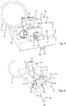
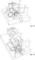
- the injection device 1 comprises a planar-shaped base 10 that serves as a mounting platform for the various components of the injection device 1.
- the injection device comprises a displaceable medicament reservoir 20, which in the present embodiment comprises a rigid cartridge with a sealed distal outlet 22 and with a oppositely located proximal portion 21 slidingly arranged in a driving unit 53 of a reservoir displacing arrangement 50.
- the injection device comprises a pressure container 40 that is fixed to the base 10.
- the pressure container 40 comprises a tubular or cylindrical shape.
- the pressure container 40 typically comprises a cylindrically-shaped barrel having a plug 47 at one end and featuring a displaceable driving piston 41 at the opposite end.
- the driving piston 41 sealing the inner volume of the barrel 44 is displaceable inside the barrel 44 along the longitudinal direction thereof.
- the driving piston 41 is mechanically engaged or is directly connected to a drive member 61 of a needle displacing arrangement 60.
- an injection needle 30 extends substantially perpendicular to the plane of the base 10.
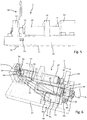
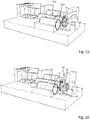
- the needle 30 is to be displaced from an initial position as illustrated in Fig. 1 into an extended position as shown in Fig. 5 , in which a dispensing end 32 of the injection needle 30 extends through and from the lower surface 11 of the base 10.
- a retraction arrangement 90 comprising a barrel 91 and a plug 95 at a proximal end facing away from the needle displacing arrangement 60.
- the opposite end of the barrel 91 is sealed with a displaceable piston 92 which is connected with a release member 93.
- the release member 93 is in turn operably engageable with a needle stopper 63.
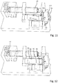
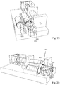
- displacement of the release piston drives the needle stopper 63 into a release position 63b in order to liberate a displacement of the drive member 61 into a second extended position 61c, as for instance indicated in Fig. 6 .
- a lock member 70 extends into or even through the needle displacing arrangement 60.
- the lock member 70 comprises a ring portion 71 and a radially outwardly extending shaft portion 72.
- the shaft portion extends through a correspondingly-shaped slot 64 of a guiding structure 65 having a through opening 66 into and through which the drive member 61 may extend in the course of the dispensing procedure.
- the through opening 66 of the guiding structure 65 is traversed by the shaft portion 72 of the lock member 70, thereby blocking a displacement of the drive member 61 in longitudinal, hence in axial direction 2.
- the axial direction refers to the tubular shape of the pressure container 40 and denotes the longitudinal axis thereof.
- the pressure container 40, the medicament reservoir 20 as well as the retraction arrangement 90 are arranged substantially parallel with respect to each other.
- the pressure container 40 is pneumatically or hydraulically coupled to the medicament reservoir 20 and to the retraction arrangement 90, the medicament reservoir 20 as well as the retraction arrangement 90 may be arranged in a different orientation compared to the longitudinal direction of the pressure container 40.
- axial direction or “axial displacement” as used herein generally refers to a longitudinal direction or longitudinal displacement in regard of a tubular barrel of different components or units of the injection device even when such barrels should not be oriented parallel to each other.
- the guiding structure 65 may be integrally formed with the base 10. It extends upwardly from the upper planar surface 12 of the base 10.
- the pressure container 40 is fixed in a first frame 13 extending upwardly from the upper surface 12 of the base 10.
- the barrel 91 of the retraction arrangement 90 is fixed on the base 10 by means of a second frame at least partially surrounding the outer circumference of the barrel 91.
- the injection device 1 is typically provided with an outer housing covering most of the components of the injection device apart from the ring portion 71 of the lock member.
- the ring portion 71 at least partially extends out of the housing in order to enable gripping thereof by a user. In the initial configuration as for instance shown in Fig.
- the lock member 70 extending into the needle displacing arrangement 60 and through or laterally across the through opening 66 may be frangibly or positively connected with a upwardly-extending shaft portion 82 of a safeguard member 80 as separately illustrated in Fig. 4 .
- the shaft portion 82 extends through a correspondingly-shaped orifice of the base 10.
- the shaft portion 82 is further connected with a gripping tab 81 extending along the lower surface 11 of the base 10 in the initial configuration as shown in Fig. 2 .
- the safeguard member 80 may be adhesively connected to the lower surface 11 of the base 10. Since the safeguard member 80 is connected with the lock member 70 the safeguard member effectively prevents unintentional or premature release and withdrawal of the lock member 70. Additionally or alternatively, the safeguard member 80 may be connected or integrated into a protective foil covering the entire lower surface 11 of the base 10. Upon removal of the protective foil, which is not illustrated, the base 10 can be attached with its lower surface 11 to a skin portion of a patient.
- safeguard member 80 and lock member 70 are positively engaged.
- a free end of the lock member's 70 shaft portion 72 comprises an orifice to receive the upward pointing shaft portion 82 of the safeguard member 80.
- the safeguard member 80 may be easily withdrawn in vertical direction, i.e. perpendicular to the plane of the base 10, thereby liberating the lock member 70.
- the lock member 70 is to be withdrawn and to be removed from the through opening 66 and out of the needle displacing arrangement's 60 shaft 64 as illustrated in Fig. 4 .
- the drive member 61 as for instance shown in Figs. 7-10 is displaceable from an initial position 61a as for instance indicated in Fig. 15 into a first extended position 61b as for instance shown in Figs. 7-10 and 17 .
- a further axially and distally-directed displacement of the drive member 61 is blocked by a needle stopper 63 extending into and through a lateral side portion of the guiding structure 65.
- the needle stopper 63 is separately illustrated in Figs. 18 and 19 .
- It comprises a T-shaped structure and has a locking pin 67 extending into the through opening 66 of the guiding structure 65 when in a stop position 63a as indicated in Fig. 18 .
- the free end of the locking pin 67 engages and abuts with a sliding block guide portion 62a of the drive member 61.
- the needle stopper 63 limits a further axial displacement of the drive member 61 under the effect of the expanding pressurized fluid 24 located in the pressure container 40.
- a further displacement of the drive member 61 into its second extended position 61c requires that the needle stopper 63 is displaced from its stop position 63a as shown in Fig. 18 into a release position 63b as shown in Fig. 19 . It is then that the needle stopper 63 liberates the drive member 61 so that the drive member 61 may be displaced further in axial direction 2 under the effect of the expanding pressurized fluid 24 until the drive member 61 reaches a second extended position as illustrated in Fig. 20 .
- a support 100 on the base 10 to receive and to mechanically support the drive member 61 when reaching the second extended position 61b.
- the support extends at the upper side 12 of the base and flushes with a lateral side of the base 10.
- the support 100 comprises a curved or semi-circular support surface 101 to receive and to support the axially extended drive member 61. In this way the support 100 serves to prevent cant of the drive member 61 and/or of the driving piston 41 with the barrel 44 of the pressure container 40.
- the drive member 61 When the drive member 61 is initially displaced from its initial position 61a into the first extended position 61b the operable engagement between the drive member 61 and the injection needle 30 leads to displacement of the injection needle 30 towards its extended position 30b.
- the injection needle 30 extending substantially perpendicular to the plane of the base 10 is rigidly connected with a needle tappet 31 extending substantially parallel to the plane of the base 10.
- the drive member 61 comprises a vertical slot 68 through which the injection needle 30 extends.
- the vertical slot 68 substantially extends over the entire elongation of the drive member 61, hence in axial direction 2. In this way, the pressurized fluid driven axial displacement of the drive member 61 has no direct effect on the position of the injection needle 30.
- the drive member 61 further comprises a sliding block guide portion 62 having a first section 62a and a second section 62b.
- First and second sections 62a, 62b are axially separated. Hence, first and second sections 62a, 62b are axially offset.
- the first and the second sections 62a, 62b extend at a certain angle relative to the axial direction 2, hence relative to the longitudinal direction of the drive member 61 or relative to the displacement direction of the drive member 61.
- the first section 62a of the sliding block guide portion 62, in which the needle tappet 31 is initially guided extends from a bottom portion of the drive member 61 towards an upper portion of the drive member 61 as seen in axial direction. Accordingly and when the drive member 61 is displaced from its initial position 61a into the first extended position 61b the needle tappet 31 experiences a downward-directed displacement, i.e. towards the base 10.
- the drive member 61 further comprises a horizontal slot 69 extending from a free end of the drive member 61 into the first section 62a of the sliding block guide portion 62.
- This groove-shaped horizontal slot 69 is particularly adapted to receive the locking pin 67 of the needle stopper 63 as the drive member 61 is displaced from its initial position 61a into its first extended position 61b. In this way, the locking pin 61 of the needle stopper 63 may abut and engage with the sliding block guide portion 62 in order to limit an axial displacement of the drive member 61.
- the sliding block guide portion 62 and the needle stopper 63 are designed and positioned in such a way, that the pressurized liquid-induced axial displacement of the drive member 61 just stops when the needle 30 has reached the extended position 30b.
- the injection needle 30 is axially sandwiched between a proximal sidewall of the guiding structure 65 and a fixing plate 74 fixedly attached to the base 10. In this way, the injection needle 30 together with its needle tappet 31 is axially constrained relative to the base 10. In this way, an axial displacement of the drive member 61 does not transfer to the injection needle 30.
- the drive member 61 is rotatably fixed in the through opening 66.
- the through opening comprises a cross-like cross-section that mates with a cross-like cross-section of the drive member 61. In this way, a rotation of the drive member 61 around its longitudinal axis can be effectively prevented.
- Axial displacement of the drive member 61 is obtained by a corresponding axial displacement of the driving piston 41 sealing the barrel 44 of the pressure container 40 in axial distal direction 2.
- the driving piston 41 is directly connected to the drive member 61. It is even conceivable, that drive member 61 and driving piston 41 are integrally formed, wherein the driving piston 41 is just equipped or provided with a sealing member to provide a fluid tight seal of the barrel 44.
- the driving piston 41 is driven from an initial position 41a into the first extended position as shown in Figs. 7-10 .
- the driving piston 41 at least partially liberates a first outlet 42 provided in the sidewall of the barrel 44 of the pressure container 40.
- the first outlet 42 is in fluid connection with a first channel 15 provided in or on the base 10.
- the channel 15 extends towards and/or into the driving unit 53.
- the first channel 15 is in fluid communication with an inlet 57 of the driving chamber 54.
- the driving chamber 54 When the driving piston 41 reaches the first extended position 41b the driving chamber 54 will get in fluid communication with the inner volume of the pressure container 40 and will therefore be exposed to the expanding pressurized fluid 24.
- the inlet 57 of the driving chamber 54 is provided in a proximal bottom portion 58 of the driving unit 53.
- the driving chamber 54 is open towards the axial distal direction 2 but is sealed by the proximal portion 21 of the medicament reservoir 20.
- the displacement of the entire medicament reservoir 20 from an initial position 28 to a dispensing position 20b is apparent from a comparison of Figs. 7 and 8 .
- the distal outlet 22 of the medicament reservoir 20 typically comprising a pierceable septum
- a tipped piercing member 55 is penetrated and pierced by a tipped piercing member 55, thereby gaining access to the inner volume of the medicament reservoir 20.
- the displacement between the initial position 20a to the dispensing position 20b is further supported and guided by a guiding member 52 arranged axially between the stop member 51 and the driving unit 53.
- the guiding member 52 comprises a through opening, in which the medicament reservoir 20 is radially supported and guided.
- the opposite end of the piercing member 55 facing away from the medicament reservoir 20 is in fluid communication with the injection needle 30 by means of e.g. a flexible tube 33 as indicated for instance in Fig. 2 .
- a flexible tube 33 to establish a fluid communication between the injection needle 30 and the piercing member 55 is beneficial in that the piercing member 55 can be fixed in an immobile way on or relative to the base 10 whereas the injection needle 30 is displaceable relative to the base between a retracted position 30a and an extended position 30b.
- the medicament reservoir 20 gets in fluid communication with the injection needle 30 and a dispensing process may start.
- a dispensing process may start.
- the liquid medicament nothing further has to be done.
- the throttle 46 is provided in the first channel 15 interconnecting the first outlet 42 of the pressure container 40 with the inlet 57 of the driving unit 53.
- a throttle 46 a rather continuous and constant influx of pressurized fluid 24 into the driving chamber 54 can be provided.
- the pressure container 40 represents a rather large source of energy, e.g. in form of a highly pressurized fluid, e.g. in form of a pressurized gas
- the throttle 46 serves to limit influx into the driving chamber 54.
- the medicament reservoir 20 in particular its distal outlet 22 is sealed as long as the medicament reservoir 20 is in its initial position 20a, any pressure applied to a proximal portion 21 of the medicament reservoir 20 leads to a distally-directed displacement of the medicament reservoir 20 relative to the base 10.
- the reservoir piston 23 sealing the proximal portion 21 of the medicament reservoir 20 can become subject to a distally-directed displacement relative to the barrel of the medicament reservoir 20, given that the fluid pressure inside the driving chamber 54 rises above a given threshold.
- the dispensing rate or the flux of the liquid medicament can be governed and controlled by the design and type of the throttle 46, the type, the amount and the pressure of the pressurized fluid 24 provided in the pressure container 40.
- At least one of the first outlet 42 or the inlet 57 provides a respective throttle function, e.g. by having a rather small channel structure or diameter through which the pressurized fluid 24 may flow. It is generally conceivable, that the flow resistance of the flow path between the pressure container 40 and the driving unit 53 and/or its driving chamber 54 is designed and realized in such a way, that a well-defined throttle function is given for the pressurized fluid.
- the flow resistance of the flow path between the pressure container 40 and the driving chamber 54 is also schematically illustrated in Fig. 25a .
- a force displacement diagram as illustrated in Fig. 25b may arise.
- the pressure inside the driving chamber 54 rises from a rather low value to a threshold value p1 in an initial phase of medicament delivery. Until the pressure in the driving chamber 54 is lower than a first threshold pressure p1, the reservoir piston 23 will not move.
- the first pressure threshold p1 is characterized by the friction between the reservoir piston 23 and the medicament reservoir 20 as well as by the viscosity of the medicament 25 and the flow resistance downstream of the medicament reservoir, e.g. in the flexible tube 33 and in the injection needle 30.
- the reservoir piston 23 starts to move in distal direction according to the further influx of the pressurized fluid 24.
- the reservoir piston 23 is almost constantly moved in distal direction.
- the reservoir piston 23 just temporally stops or retardates, e.g. due to locally increased friction forces, which may result from manufacturing tolerances of e.g. the medicament reservoir 20.
- the force for moving the reservoir piston 23 and hence the pressure proportional to said force rises until the reservoir piston 23 is moved further in distal direction as illustrated by the falling slope h.
- the displacement velocity of the reservoir piston 23 may be subject to variations.
- the pressurized fluid 24 is compressible and since the influx of the pressurized fluid 24 into the driving chamber 54 is substantially constant, the average displacement velocity of the reservoir piston 23 during a dispensing action will be substantially constant for a large variety of medicament reservoirs 20.
- distally-directed displacement of the reservoir piston 23 continues over a further region d until the reservoir piston 23 hits a distal end of the medicament reservoir 20. Since the reservoir piston 23 cannot move any further in distal direction, the pressure in region e rises up to a maximum pressure pmax as indicated by the rising slope j.
- Figs. 26a and 26b an alternative embodiment is illustrated, wherein the flow path between the pressure container 40 and the driving chamber 54 not only comprises a throttle 46 but also a pressure-sensitive valve 36, e.g. in form of a check valve.
- the pressure-sensitive valve 36 is substantially open below a predefined fluid pressure p0 which is only slightly smaller than the threshold pressure p1, at which the reservoir piston 23 starts to move.
- the throttle 46 limiting an initial pressure build up in region a can be accelerated as indicated by the arrow f.
- flushing of the driving chamber 54 with the pressurized fluid 24 can be accelerated, so that reservoir piston 23 displacement and hence medicament delivery may almost immediately start after the fluid communication between the driving chamber 54 and the pressure container 40 is established.
- the medicament reservoir 20 can be displaced towards the stop member 51 with a well-defined velocity and impact to establish a rather rapid and loss less fluid communication between the medicament reservoir 30 and the piercing member 52.
- a discharge outlet 56 in the bottom portion 58 of the driving chamber 54 is opened.
- said discharge outlet 56 is closed and sealed by a removable plug 59.
- the plug 59 is axially displaced into the driving chamber 54, thereby liberating the discharge outlet 56.
- the discharge outlet 56 is in flow communication with an inlet 94 of the retraction arrangement 90, in particular of the barrel 91 as shown in Fig. 6 .
- the fluid communication between the discharge outlet 56 and the inlet 94 is provided by a second channel 16 which may be provided in or on the base 10.
- a second channel 16 which may be provided in or on the base 10.
- Fig. 19 a comparison of Figs. 14 and 19 illustrates the radial or horizontal displacement of the needle stopper 63 under the action of the retraction arrangement 90. Consequently and during the further pressurized fluid 24 driven axial displacement of the drive member 61 into its second extended position 61c, the needle tappet 31 is guided in the second section 62b of the sliding block guide portion 62 of the drive member 61.
- the needle tappet 31 and hence the injection needle 30 experiences an upward-directed displacement.
- the injection needle 30 is displaced from its extended position 30b into its retracted position 30a as indicated in Fig. 20 .
- the driving piston 41 is displaced into its second extended position 41c as indicated in Fig. 20 .
- the driving piston 41 then reaches a distal end position.
- a distal end of the drive member 61 even protrudes from the base 10 and hence from a not illustrated housing of the injection device 1 when the drive member 61 is in its second extended position 61c. In this way, a visual and haptic or tactile feedback can be provided to the user indicating the injection process has terminated.
- the pressure container 40 in particular its barrel 44 comprises a second outlet 43 as for instance shown in Fig. 12 , wherein the driving piston 41 and the drive member 61 are faded out.
- the second outlet 43 is in fluid communication with a signal generator 45 via a third channel 17 as indicated by the dashed lines in Fig. 6 .
- the third channel 17 and the signal generator 45 typically designed as whistle or the like acoustic signal generating means, the excess pressurized fluid 24 can be relieved to the environment.
- the outlet opening of the signal generator 45 is further shown in Fig. 5 .
- the signal generator 45 as well as the third channel 17 may be integrated into the base 10.
- the base 10 is manufactured as an injection molded plastic component. In this way, at least one or several of the first, the second or the third channel 15, 16, 17 as well as the acoustic signal generator 45 may be easily integrated with a manufacturer, almost cost neutral.
- the second outlet 43 is liberated as soon as the driving piston 41 reaches its second extended position 41c at the end of a dispensing procedure. In this way not only an acoustic signal indicating termination of the injection process is provided but the injection device also becomes substantially pressureless, which may be of particular benefit for discarding or recycling the injection device 1.
- the injection device 1 is designed as a disposable device, which is to be entirely discarded after the injection has been executed.
- the reservoir piston 23 is mechanically connected with said plug 59.
- the reservoir piston 23 may be connected with the plug 59 via a rope or a similar force transferring means.
- the reservoir piston 23 Upon approaching a distal end position the reservoir piston 23 will start to tighten the rope and to withdraw the plug 59 from the discharge outlet 56.
- the medicament reservoir 20 in form of a cartridge comprises two pistons, a distal reservoir piston 23 and an additional pressure receiving piston 26.
- the pressure receiving piston 26 is mechanically engaged with the plug 59 via a flexible rope 27.
- Fig. 21a In an initial configuration as illustrated in Fig. 21a , the medicament reservoir 20 is in its initial position 20a.
- Fig. 21b the pressure inside the driving chamber 54 has increased. Consequently, the medicament reservoir 20 is displaced in distal or in dispensing direction 3 until it hits and engages with the stop member 51.
- Fig. 21c reflects a configuration during medicament delivery.
- the intermediate space 28 between the two pistons 23, 26 is typically filled with a compressible substance, such like a gas. As long as the reservoir piston 23 is displaceable relative to the medicament reservoir 20, the pressure acting on the pressure receiving piston 26 is transferred via the compressible substance in the intermediate space 28 to the reservoir piston 23.
- check valve in the flow path between the pressure container 40 and the driving chamber 54.
- This check valve may operate in a sense, that it is adapted to open a discharge outlet when the pressure in the flow path rises above a maximum threshold. Opening of such a check valve would then redirect the pressurized fluid 24 of the pressure container 40 directly into the barrel 91 of the retraction arrangement 90.
- the stop member 51 of the reservoir displacing arrangement 50 comprises a bending member 34 located between the distal outlet 22 of the medicament reservoir 20 and a proximal side of the stop member 51.
- the bending member 34 features a rather planar shape and further has an end portion 34 axially engaging with the drive member 61 in a way similar as described above in connection with the needle stopper 63.
- the end portion 35 of the bending member 34 acts as an axial stop for the drive member 61 for keeping the drive member 61 in the first extended position 61b.
- the bending member 34 starts to deform under the action of the rising pressure.
- the bending member 34' approaches a bended geometry, whereby the end portion 35 of the bending member 34 is displaced in such a way, that the axial abutment between the bending member 34 and the drive member 61 is abrogated.
- the drive member 61 becomes liberated and may be further displaced towards its second extended position 61c as indicated in Fig. 24b .
- the pressure container 40 can comprise or may be coupled with a pressure display 48 comprising a window 49 in which a pressure indicator 38 is displaceable against the action of a spring element 39.
- the pressure indicator 38 comprises at least two different pressure indicating sections 38a, 38b visually indicating if the fluid pressure inside the pressure container 40 is sufficient for conducting a dispensing procedure.
- the pressure indicating sections 38a, 38b are arranged next to each other in direction of a displacing direction of the spring element 39.
- the pressure indicator 38 is in fluid communication with the pressurized fluid 24 contained in the pressure container 40.
- the spring element 39 will expand to a certain degree as illustrated in Fig. 22 . Consequently, the pressure indicating section 38a indicating a rather low pressure will visibly appear in the window 49 of the pressure display 48. If the pressure is sufficiently high, the spring element 39 will be compressed as indicated in Fig. 23 . Consequently, a different pressure indicating section 38b will appear in the window 49, thereby indicating, that the pressure of the pressurized fluid 24 is high enough to conduct a dispensing or injection procedure.
- substantially valveless means a configuration wherein a user does not have to operate a valve in order to trigger subsequent steps of the injection process.
Landscapes
- Health & Medical Sciences (AREA)
- Life Sciences & Earth Sciences (AREA)
- Animal Behavior & Ethology (AREA)
- Engineering & Computer Science (AREA)
- Anesthesiology (AREA)
- Biomedical Technology (AREA)
- Heart & Thoracic Surgery (AREA)
- Vascular Medicine (AREA)
- Veterinary Medicine (AREA)
- Hematology (AREA)
- General Health & Medical Sciences (AREA)
- Public Health (AREA)
- Dermatology (AREA)
- Physics & Mathematics (AREA)
- Fluid Mechanics (AREA)
- Infusion, Injection, And Reservoir Apparatuses (AREA)
Priority Applications (1)
| Application Number | Priority Date | Filing Date | Title |
|---|---|---|---|
| EP14784471.6A EP3057630B1 (en) | 2013-10-18 | 2014-10-16 | Injection device for delivery of a liquid medicament with medicament container displacement |
Applications Claiming Priority (3)
| Application Number | Priority Date | Filing Date | Title |
|---|---|---|---|
| EP13189313 | 2013-10-18 | ||
| PCT/EP2014/072174 WO2015055747A1 (en) | 2013-10-18 | 2014-10-16 | Injection device for delivery of a liquid medicament with medicament container displacement |
| EP14784471.6A EP3057630B1 (en) | 2013-10-18 | 2014-10-16 | Injection device for delivery of a liquid medicament with medicament container displacement |
Publications (2)
| Publication Number | Publication Date |
|---|---|
| EP3057630A1 EP3057630A1 (en) | 2016-08-24 |
| EP3057630B1 true EP3057630B1 (en) | 2019-02-06 |
Family
ID=49513719
Family Applications (1)
| Application Number | Title | Priority Date | Filing Date |
|---|---|---|---|
| EP14784471.6A Active EP3057630B1 (en) | 2013-10-18 | 2014-10-16 | Injection device for delivery of a liquid medicament with medicament container displacement |
Country Status (8)
| Country | Link |
|---|---|
| US (1) | US10251997B2 (zh) |
| EP (1) | EP3057630B1 (zh) |
| JP (1) | JP2016533213A (zh) |
| CN (1) | CN105979986A (zh) |
| DK (1) | DK3057630T3 (zh) |
| TR (1) | TR201905105T4 (zh) |
| TW (1) | TW201521816A (zh) |
| WO (1) | WO2015055747A1 (zh) |
Families Citing this family (9)
| Publication number | Priority date | Publication date | Assignee | Title |
|---|---|---|---|---|
| WO2018082891A1 (en) * | 2016-11-01 | 2018-05-11 | Sanofi-Aventis Deutschland Gmbh | Feedback mechanism for an injection device |
| FR3063015B1 (fr) * | 2017-02-20 | 2021-10-01 | Aptar France Sas | Dispositif d'injection automatique de produit fluide. |
| CA3052482A1 (en) * | 2017-03-07 | 2018-09-13 | Amgen Inc. | Needle insertion by overpressure |
| US11040137B2 (en) * | 2017-05-19 | 2021-06-22 | Min Wei | Wearable drug delivery device |
| US10994116B2 (en) | 2018-06-30 | 2021-05-04 | Bioq Pharma Incorporated | Drug cartridge-based infusion pump |
| CN110207989B (zh) * | 2019-05-29 | 2021-12-14 | 太原理工大学 | 一种发动机台架自动对中调节系统 |
| WO2023091922A2 (en) * | 2021-11-16 | 2023-05-25 | Regeneron Pharmaceuticals, Inc. | Auto-injector and related methods of use |
| USD1007676S1 (en) | 2021-11-16 | 2023-12-12 | Regeneron Pharmaceuticals, Inc. | Wearable autoinjector |
| CN114632218B (zh) * | 2022-03-14 | 2024-03-08 | 重庆倍加医疗器械有限公司 | 一种气压驱动注射装置 |
Citations (1)
| Publication number | Priority date | Publication date | Assignee | Title |
|---|---|---|---|---|
| WO2011116304A1 (en) * | 2010-03-19 | 2011-09-22 | Halozyme, Inc. | Gas-pressured medication delivery device |
Family Cites Families (5)
| Publication number | Priority date | Publication date | Assignee | Title |
|---|---|---|---|---|
| CA2151407A1 (en) * | 1995-06-09 | 1996-12-10 | Duncan Newman | Injection device |
| KR20040103930A (ko) * | 2002-02-11 | 2004-12-09 | 앤태어스 파머, 인코퍼레이티드 | 피내 주사기 |
| US7648483B2 (en) * | 2004-11-22 | 2010-01-19 | Intelliject, Inc. | Devices, systems and methods for medicament delivery |
| NZ570731A (en) * | 2006-03-29 | 2011-07-29 | Intelliject Inc | Device to deliver medication with circuit producing recorded speech output and movable structure to effectuate delivery and circuit |
| GB0913136D0 (en) * | 2009-07-28 | 2009-09-02 | Ucb Pharma Sa | Auto-injector |
-
2014
- 2014-10-16 DK DK14784471.6T patent/DK3057630T3/en active
- 2014-10-16 EP EP14784471.6A patent/EP3057630B1/en active Active
- 2014-10-16 CN CN201480067306.7A patent/CN105979986A/zh active Pending
- 2014-10-16 US US15/026,708 patent/US10251997B2/en active Active
- 2014-10-16 JP JP2016521988A patent/JP2016533213A/ja active Pending
- 2014-10-16 TW TW103135772A patent/TW201521816A/zh unknown
- 2014-10-16 WO PCT/EP2014/072174 patent/WO2015055747A1/en active Application Filing
- 2014-10-16 TR TR2019/05105T patent/TR201905105T4/tr unknown
Patent Citations (1)
| Publication number | Priority date | Publication date | Assignee | Title |
|---|---|---|---|---|
| WO2011116304A1 (en) * | 2010-03-19 | 2011-09-22 | Halozyme, Inc. | Gas-pressured medication delivery device |
Also Published As
| Publication number | Publication date |
|---|---|
| TW201521816A (zh) | 2015-06-16 |
| EP3057630A1 (en) | 2016-08-24 |
| WO2015055747A1 (en) | 2015-04-23 |
| JP2016533213A (ja) | 2016-10-27 |
| TR201905105T4 (tr) | 2019-05-21 |
| DK3057630T3 (en) | 2019-04-29 |
| CN105979986A (zh) | 2016-09-28 |
| US10251997B2 (en) | 2019-04-09 |
| US20160250411A1 (en) | 2016-09-01 |
Similar Documents
| Publication | Publication Date | Title |
|---|---|---|
| EP3057630B1 (en) | Injection device for delivery of a liquid medicament with medicament container displacement | |
| EP3434302B1 (en) | Autoinjector | |
| EP3062849B1 (en) | Medicament delivery device | |
| EP3142730B1 (en) | Medicament delivery device having an activating mechanism | |
| EP3060278B1 (en) | Medicament delivery device with two drive springs | |
| EP3099356B1 (en) | Medicament delivery device | |
| EP3019216B1 (en) | Autoinjector | |
| EP3151886B1 (en) | Activating mechanism for a medicament delivery device and medicament delivery device | |
| EP3142729B1 (en) | Activating mechanism for a medicament delivery device and medicament delivery device | |
| US20210220560A1 (en) | Injection Device and Container for an Injection Device | |
| EP2661298B1 (en) | Safety device and injection device | |
| EP2906275B1 (en) | Needle assembly attachable to an injection device, the needle assembly having a reservoir assembly with locking mechanism |
Legal Events
| Date | Code | Title | Description |
|---|---|---|---|
| PUAI | Public reference made under article 153(3) epc to a published international application that has entered the european phase |
Free format text: ORIGINAL CODE: 0009012 |
|
| 17P | Request for examination filed |
Effective date: 20160518 |
|
| AK | Designated contracting states |
Kind code of ref document: A1 Designated state(s): AL AT BE BG CH CY CZ DE DK EE ES FI FR GB GR HR HU IE IS IT LI LT LU LV MC MK MT NL NO PL PT RO RS SE SI SK SM TR |
|
| AX | Request for extension of the european patent |
Extension state: BA ME |
|
| DAX | Request for extension of the european patent (deleted) | ||
| REG | Reference to a national code |
Ref country code: HK Ref legal event code: DE Ref document number: 1224972 Country of ref document: HK |
|
| REG | Reference to a national code |
Ref country code: DE Ref legal event code: R079 Ref document number: 602014040767 Country of ref document: DE Free format text: PREVIOUS MAIN CLASS: A61M0005200000 Ipc: A61M0005142000 |
|
| RIC1 | Information provided on ipc code assigned before grant |
Ipc: A61M 5/145 20060101ALI20180125BHEP Ipc: A61M 5/155 20060101ALI20180125BHEP Ipc: A61M 5/315 20060101ALI20180125BHEP Ipc: A61M 5/142 20060101AFI20180125BHEP |
|
| GRAP | Despatch of communication of intention to grant a patent |
Free format text: ORIGINAL CODE: EPIDOSNIGR1 |
|
| STAA | Information on the status of an ep patent application or granted ep patent |
Free format text: STATUS: GRANT OF PATENT IS INTENDED |
|
| INTG | Intention to grant announced |
Effective date: 20180319 |
|
| GRAJ | Information related to disapproval of communication of intention to grant by the applicant or resumption of examination proceedings by the epo deleted |
Free format text: ORIGINAL CODE: EPIDOSDIGR1 |
|
| STAA | Information on the status of an ep patent application or granted ep patent |
Free format text: STATUS: REQUEST FOR EXAMINATION WAS MADE |
|
| INTC | Intention to grant announced (deleted) | ||
| GRAP | Despatch of communication of intention to grant a patent |
Free format text: ORIGINAL CODE: EPIDOSNIGR1 |
|
| STAA | Information on the status of an ep patent application or granted ep patent |
Free format text: STATUS: GRANT OF PATENT IS INTENDED |
|
| INTG | Intention to grant announced |
Effective date: 20180816 |
|
| GRAS | Grant fee paid |
Free format text: ORIGINAL CODE: EPIDOSNIGR3 |
|
| GRAA | (expected) grant |
Free format text: ORIGINAL CODE: 0009210 |
|
| STAA | Information on the status of an ep patent application or granted ep patent |
Free format text: STATUS: THE PATENT HAS BEEN GRANTED |
|
| AK | Designated contracting states |
Kind code of ref document: B1 Designated state(s): AL AT BE BG CH CY CZ DE DK EE ES FI FR GB GR HR HU IE IS IT LI LT LU LV MC MK MT NL NO PL PT RO RS SE SI SK SM TR |
|
| REG | Reference to a national code |
Ref country code: GB Ref legal event code: FG4D |
|
| REG | Reference to a national code |
Ref country code: CH Ref legal event code: EP Ref country code: AT Ref legal event code: REF Ref document number: 1094449 Country of ref document: AT Kind code of ref document: T Effective date: 20190215 |
|
| REG | Reference to a national code |
Ref country code: IE Ref legal event code: FG4D |
|
| REG | Reference to a national code |
Ref country code: DE Ref legal event code: R096 Ref document number: 602014040767 Country of ref document: DE |
|
| REG | Reference to a national code |
Ref country code: DK Ref legal event code: T3 Effective date: 20190423 |
|
| REG | Reference to a national code |
Ref country code: NL Ref legal event code: MP Effective date: 20190206 |
|
| REG | Reference to a national code |
Ref country code: LT Ref legal event code: MG4D |
|
| PG25 | Lapsed in a contracting state [announced via postgrant information from national office to epo] |
Ref country code: NO Free format text: LAPSE BECAUSE OF FAILURE TO SUBMIT A TRANSLATION OF THE DESCRIPTION OR TO PAY THE FEE WITHIN THE PRESCRIBED TIME-LIMIT Effective date: 20190506 Ref country code: LT Free format text: LAPSE BECAUSE OF FAILURE TO SUBMIT A TRANSLATION OF THE DESCRIPTION OR TO PAY THE FEE WITHIN THE PRESCRIBED TIME-LIMIT Effective date: 20190206 Ref country code: FI Free format text: LAPSE BECAUSE OF FAILURE TO SUBMIT A TRANSLATION OF THE DESCRIPTION OR TO PAY THE FEE WITHIN THE PRESCRIBED TIME-LIMIT Effective date: 20190206 Ref country code: NL Free format text: LAPSE BECAUSE OF FAILURE TO SUBMIT A TRANSLATION OF THE DESCRIPTION OR TO PAY THE FEE WITHIN THE PRESCRIBED TIME-LIMIT Effective date: 20190206 Ref country code: PT Free format text: LAPSE BECAUSE OF FAILURE TO SUBMIT A TRANSLATION OF THE DESCRIPTION OR TO PAY THE FEE WITHIN THE PRESCRIBED TIME-LIMIT Effective date: 20190606 Ref country code: SE Free format text: LAPSE BECAUSE OF FAILURE TO SUBMIT A TRANSLATION OF THE DESCRIPTION OR TO PAY THE FEE WITHIN THE PRESCRIBED TIME-LIMIT Effective date: 20190206 |
|
| REG | Reference to a national code |
Ref country code: AT Ref legal event code: MK05 Ref document number: 1094449 Country of ref document: AT Kind code of ref document: T Effective date: 20190206 |
|
| PG25 | Lapsed in a contracting state [announced via postgrant information from national office to epo] |
Ref country code: HR Free format text: LAPSE BECAUSE OF FAILURE TO SUBMIT A TRANSLATION OF THE DESCRIPTION OR TO PAY THE FEE WITHIN THE PRESCRIBED TIME-LIMIT Effective date: 20190206 Ref country code: IS Free format text: LAPSE BECAUSE OF FAILURE TO SUBMIT A TRANSLATION OF THE DESCRIPTION OR TO PAY THE FEE WITHIN THE PRESCRIBED TIME-LIMIT Effective date: 20190606 Ref country code: LV Free format text: LAPSE BECAUSE OF FAILURE TO SUBMIT A TRANSLATION OF THE DESCRIPTION OR TO PAY THE FEE WITHIN THE PRESCRIBED TIME-LIMIT Effective date: 20190206 Ref country code: GR Free format text: LAPSE BECAUSE OF FAILURE TO SUBMIT A TRANSLATION OF THE DESCRIPTION OR TO PAY THE FEE WITHIN THE PRESCRIBED TIME-LIMIT Effective date: 20190507 Ref country code: BG Free format text: LAPSE BECAUSE OF FAILURE TO SUBMIT A TRANSLATION OF THE DESCRIPTION OR TO PAY THE FEE WITHIN THE PRESCRIBED TIME-LIMIT Effective date: 20190506 Ref country code: RS Free format text: LAPSE BECAUSE OF FAILURE TO SUBMIT A TRANSLATION OF THE DESCRIPTION OR TO PAY THE FEE WITHIN THE PRESCRIBED TIME-LIMIT Effective date: 20190206 |
|
| PG25 | Lapsed in a contracting state [announced via postgrant information from national office to epo] |
Ref country code: EE Free format text: LAPSE BECAUSE OF FAILURE TO SUBMIT A TRANSLATION OF THE DESCRIPTION OR TO PAY THE FEE WITHIN THE PRESCRIBED TIME-LIMIT Effective date: 20190206 Ref country code: ES Free format text: LAPSE BECAUSE OF FAILURE TO SUBMIT A TRANSLATION OF THE DESCRIPTION OR TO PAY THE FEE WITHIN THE PRESCRIBED TIME-LIMIT Effective date: 20190206 Ref country code: CZ Free format text: LAPSE BECAUSE OF FAILURE TO SUBMIT A TRANSLATION OF THE DESCRIPTION OR TO PAY THE FEE WITHIN THE PRESCRIBED TIME-LIMIT Effective date: 20190206 Ref country code: RO Free format text: LAPSE BECAUSE OF FAILURE TO SUBMIT A TRANSLATION OF THE DESCRIPTION OR TO PAY THE FEE WITHIN THE PRESCRIBED TIME-LIMIT Effective date: 20190206 Ref country code: IT Free format text: LAPSE BECAUSE OF FAILURE TO SUBMIT A TRANSLATION OF THE DESCRIPTION OR TO PAY THE FEE WITHIN THE PRESCRIBED TIME-LIMIT Effective date: 20190206 Ref country code: SK Free format text: LAPSE BECAUSE OF FAILURE TO SUBMIT A TRANSLATION OF THE DESCRIPTION OR TO PAY THE FEE WITHIN THE PRESCRIBED TIME-LIMIT Effective date: 20190206 Ref country code: AL Free format text: LAPSE BECAUSE OF FAILURE TO SUBMIT A TRANSLATION OF THE DESCRIPTION OR TO PAY THE FEE WITHIN THE PRESCRIBED TIME-LIMIT Effective date: 20190206 |
|
| REG | Reference to a national code |
Ref country code: DE Ref legal event code: R097 Ref document number: 602014040767 Country of ref document: DE |
|
| PG25 | Lapsed in a contracting state [announced via postgrant information from national office to epo] |
Ref country code: SM Free format text: LAPSE BECAUSE OF FAILURE TO SUBMIT A TRANSLATION OF THE DESCRIPTION OR TO PAY THE FEE WITHIN THE PRESCRIBED TIME-LIMIT Effective date: 20190206 Ref country code: PL Free format text: LAPSE BECAUSE OF FAILURE TO SUBMIT A TRANSLATION OF THE DESCRIPTION OR TO PAY THE FEE WITHIN THE PRESCRIBED TIME-LIMIT Effective date: 20190206 |
|
| PLBE | No opposition filed within time limit |
Free format text: ORIGINAL CODE: 0009261 |
|
| STAA | Information on the status of an ep patent application or granted ep patent |
Free format text: STATUS: NO OPPOSITION FILED WITHIN TIME LIMIT |
|
| PG25 | Lapsed in a contracting state [announced via postgrant information from national office to epo] |
Ref country code: AT Free format text: LAPSE BECAUSE OF FAILURE TO SUBMIT A TRANSLATION OF THE DESCRIPTION OR TO PAY THE FEE WITHIN THE PRESCRIBED TIME-LIMIT Effective date: 20190206 |
|
| 26N | No opposition filed |
Effective date: 20191107 |
|
| PG25 | Lapsed in a contracting state [announced via postgrant information from national office to epo] |
Ref country code: SI Free format text: LAPSE BECAUSE OF FAILURE TO SUBMIT A TRANSLATION OF THE DESCRIPTION OR TO PAY THE FEE WITHIN THE PRESCRIBED TIME-LIMIT Effective date: 20190206 |
|
| PG25 | Lapsed in a contracting state [announced via postgrant information from national office to epo] |
Ref country code: MC Free format text: LAPSE BECAUSE OF FAILURE TO SUBMIT A TRANSLATION OF THE DESCRIPTION OR TO PAY THE FEE WITHIN THE PRESCRIBED TIME-LIMIT Effective date: 20190206 |
|
| PG25 | Lapsed in a contracting state [announced via postgrant information from national office to epo] |
Ref country code: LU Free format text: LAPSE BECAUSE OF NON-PAYMENT OF DUE FEES Effective date: 20191016 |
|
| REG | Reference to a national code |
Ref country code: BE Ref legal event code: MM Effective date: 20191031 |
|
| PG25 | Lapsed in a contracting state [announced via postgrant information from national office to epo] |
Ref country code: BE Free format text: LAPSE BECAUSE OF NON-PAYMENT OF DUE FEES Effective date: 20191031 |
|
| PG25 | Lapsed in a contracting state [announced via postgrant information from national office to epo] |
Ref country code: IE Free format text: LAPSE BECAUSE OF NON-PAYMENT OF DUE FEES Effective date: 20191016 |
|
| PG25 | Lapsed in a contracting state [announced via postgrant information from national office to epo] |
Ref country code: CY Free format text: LAPSE BECAUSE OF FAILURE TO SUBMIT A TRANSLATION OF THE DESCRIPTION OR TO PAY THE FEE WITHIN THE PRESCRIBED TIME-LIMIT Effective date: 20190206 |
|
| PG25 | Lapsed in a contracting state [announced via postgrant information from national office to epo] |
Ref country code: HU Free format text: LAPSE BECAUSE OF FAILURE TO SUBMIT A TRANSLATION OF THE DESCRIPTION OR TO PAY THE FEE WITHIN THE PRESCRIBED TIME-LIMIT; INVALID AB INITIO Effective date: 20141016 Ref country code: MT Free format text: LAPSE BECAUSE OF FAILURE TO SUBMIT A TRANSLATION OF THE DESCRIPTION OR TO PAY THE FEE WITHIN THE PRESCRIBED TIME-LIMIT Effective date: 20190206 |
|
| PG25 | Lapsed in a contracting state [announced via postgrant information from national office to epo] |
Ref country code: MK Free format text: LAPSE BECAUSE OF FAILURE TO SUBMIT A TRANSLATION OF THE DESCRIPTION OR TO PAY THE FEE WITHIN THE PRESCRIBED TIME-LIMIT Effective date: 20190206 |
|
| REG | Reference to a national code |
Ref country code: HK Ref legal event code: WD Ref document number: 1224972 Country of ref document: HK |
|
| PGFP | Annual fee paid to national office [announced via postgrant information from national office to epo] |
Ref country code: GB Payment date: 20230831 Year of fee payment: 10 |
|
| PGFP | Annual fee paid to national office [announced via postgrant information from national office to epo] |
Ref country code: FR Payment date: 20230911 Year of fee payment: 10 |
|
| PGFP | Annual fee paid to national office [announced via postgrant information from national office to epo] |
Ref country code: DK Payment date: 20231016 Year of fee payment: 10 Ref country code: DE Payment date: 20230830 Year of fee payment: 10 Ref country code: CH Payment date: 20231102 Year of fee payment: 10 |