EP3053656A1 - Liquid supply system for a gravity feed spray device - Google Patents
Liquid supply system for a gravity feed spray device Download PDFInfo
- Publication number
- EP3053656A1 EP3053656A1 EP16161559.6A EP16161559A EP3053656A1 EP 3053656 A1 EP3053656 A1 EP 3053656A1 EP 16161559 A EP16161559 A EP 16161559A EP 3053656 A1 EP3053656 A1 EP 3053656A1
- Authority
- EP
- European Patent Office
- Prior art keywords
- valve
- container
- assembly
- filter assembly
- spray
- Prior art date
- Legal status (The legal status is an assumption and is not a legal conclusion. Google has not performed a legal analysis and makes no representation as to the accuracy of the status listed.)
- Withdrawn
Links
- 230000005484 gravity Effects 0.000 title claims abstract description 36
- 239000007921 spray Substances 0.000 title claims description 52
- 239000007788 liquid Substances 0.000 title description 65
- 239000012530 fluid Substances 0.000 claims abstract description 8
- 239000000463 material Substances 0.000 claims description 65
- 238000001914 filtration Methods 0.000 claims description 12
- 238000000034 method Methods 0.000 claims description 11
- 238000005507 spraying Methods 0.000 description 51
- 239000011248 coating agent Substances 0.000 description 37
- 238000000576 coating method Methods 0.000 description 37
- 238000000889 atomisation Methods 0.000 description 10
- 230000015572 biosynthetic process Effects 0.000 description 6
- 238000002156 mixing Methods 0.000 description 6
- 230000007246 mechanism Effects 0.000 description 5
- 239000000203 mixture Substances 0.000 description 5
- 239000000835 fiber Substances 0.000 description 4
- 239000004033 plastic Substances 0.000 description 4
- 229920003023 plastic Polymers 0.000 description 4
- 230000000712 assembly Effects 0.000 description 3
- 238000000429 assembly Methods 0.000 description 3
- 230000008878 coupling Effects 0.000 description 3
- 238000010168 coupling process Methods 0.000 description 3
- 238000005859 coupling reaction Methods 0.000 description 3
- -1 e.g. Polymers 0.000 description 3
- 230000008569 process Effects 0.000 description 3
- 239000004698 Polyethylene Substances 0.000 description 2
- 230000008901 benefit Effects 0.000 description 2
- 230000000903 blocking effect Effects 0.000 description 2
- 238000013461 design Methods 0.000 description 2
- 238000011161 development Methods 0.000 description 2
- 238000009826 distribution Methods 0.000 description 2
- 238000001035 drying Methods 0.000 description 2
- 238000004519 manufacturing process Methods 0.000 description 2
- 238000005259 measurement Methods 0.000 description 2
- 238000012986 modification Methods 0.000 description 2
- 230000004048 modification Effects 0.000 description 2
- 238000012856 packing Methods 0.000 description 2
- 239000003973 paint Substances 0.000 description 2
- 229920000573 polyethylene Polymers 0.000 description 2
- 229920000642 polymer Polymers 0.000 description 2
- 238000007493 shaping process Methods 0.000 description 2
- 238000003860 storage Methods 0.000 description 2
- 230000007704 transition Effects 0.000 description 2
- 235000017166 Bambusa arundinacea Nutrition 0.000 description 1
- 235000017491 Bambusa tulda Nutrition 0.000 description 1
- 241001330002 Bambuseae Species 0.000 description 1
- 229920003043 Cellulose fiber Polymers 0.000 description 1
- 239000004677 Nylon Substances 0.000 description 1
- 235000015334 Phyllostachys viridis Nutrition 0.000 description 1
- 229920002522 Wood fibre Polymers 0.000 description 1
- 238000004026 adhesive bonding Methods 0.000 description 1
- 229920003235 aromatic polyamide Polymers 0.000 description 1
- 239000011425 bamboo Substances 0.000 description 1
- 229920002678 cellulose Polymers 0.000 description 1
- 239000001913 cellulose Substances 0.000 description 1
- 238000004140 cleaning Methods 0.000 description 1
- 229920001971 elastomer Polymers 0.000 description 1
- 239000000806 elastomer Substances 0.000 description 1
- 238000001125 extrusion Methods 0.000 description 1
- 239000011261 inert gas Substances 0.000 description 1
- 229910052500 inorganic mineral Inorganic materials 0.000 description 1
- 239000012528 membrane Substances 0.000 description 1
- 239000002184 metal Substances 0.000 description 1
- 239000007769 metal material Substances 0.000 description 1
- 239000011707 mineral Substances 0.000 description 1
- 239000002557 mineral fiber Substances 0.000 description 1
- 229920001778 nylon Polymers 0.000 description 1
- 229920000728 polyester Polymers 0.000 description 1
- 229920005594 polymer fiber Polymers 0.000 description 1
- 229920000098 polyolefin Polymers 0.000 description 1
- 229920002635 polyurethane Polymers 0.000 description 1
- 239000004814 polyurethane Substances 0.000 description 1
- 229920000915 polyvinyl chloride Polymers 0.000 description 1
- 239000004800 polyvinyl chloride Substances 0.000 description 1
- 238000002360 preparation method Methods 0.000 description 1
- 238000007789 sealing Methods 0.000 description 1
- 239000002904 solvent Substances 0.000 description 1
- 238000012546 transfer Methods 0.000 description 1
- 235000013311 vegetables Nutrition 0.000 description 1
- 239000002699 waste material Substances 0.000 description 1
- 238000003466 welding Methods 0.000 description 1
- 239000002025 wood fiber Substances 0.000 description 1
Images


Classifications
-
- B—PERFORMING OPERATIONS; TRANSPORTING
- B05—SPRAYING OR ATOMISING IN GENERAL; APPLYING FLUENT MATERIALS TO SURFACES, IN GENERAL
- B05B—SPRAYING APPARATUS; ATOMISING APPARATUS; NOZZLES
- B05B7/00—Spraying apparatus for discharge of liquids or other fluent materials from two or more sources, e.g. of liquid and air, of powder and gas
- B05B7/02—Spray pistols; Apparatus for discharge
- B05B7/08—Spray pistols; Apparatus for discharge with separate outlet orifices, e.g. to form parallel jets, i.e. the axis of the jets being parallel, to form intersecting jets, i.e. the axis of the jets converging but not necessarily intersecting at a point
- B05B7/0807—Spray pistols; Apparatus for discharge with separate outlet orifices, e.g. to form parallel jets, i.e. the axis of the jets being parallel, to form intersecting jets, i.e. the axis of the jets converging but not necessarily intersecting at a point to form intersecting jets
- B05B7/0815—Spray pistols; Apparatus for discharge with separate outlet orifices, e.g. to form parallel jets, i.e. the axis of the jets being parallel, to form intersecting jets, i.e. the axis of the jets converging but not necessarily intersecting at a point to form intersecting jets with at least one gas jet intersecting a jet constituted by a liquid or a mixture containing a liquid for controlling the shape of the latter
-
- B—PERFORMING OPERATIONS; TRANSPORTING
- B05—SPRAYING OR ATOMISING IN GENERAL; APPLYING FLUENT MATERIALS TO SURFACES, IN GENERAL
- B05B—SPRAYING APPARATUS; ATOMISING APPARATUS; NOZZLES
- B05B15/00—Details of spraying plant or spraying apparatus not otherwise provided for; Accessories
- B05B15/40—Filters located upstream of the spraying outlets
-
- B—PERFORMING OPERATIONS; TRANSPORTING
- B05—SPRAYING OR ATOMISING IN GENERAL; APPLYING FLUENT MATERIALS TO SURFACES, IN GENERAL
- B05B—SPRAYING APPARATUS; ATOMISING APPARATUS; NOZZLES
- B05B7/00—Spraying apparatus for discharge of liquids or other fluent materials from two or more sources, e.g. of liquid and air, of powder and gas
- B05B7/24—Spraying apparatus for discharge of liquids or other fluent materials from two or more sources, e.g. of liquid and air, of powder and gas with means, e.g. a container, for supplying liquid or other fluent material to a discharge device
- B05B7/2402—Apparatus to be carried on or by a person, e.g. by hand; Apparatus comprising containers fixed to the discharge device
- B05B7/2405—Apparatus to be carried on or by a person, e.g. by hand; Apparatus comprising containers fixed to the discharge device using an atomising fluid as carrying fluid for feeding, e.g. by suction or pressure, a carried liquid from the container to the nozzle
- B05B7/2408—Apparatus to be carried on or by a person, e.g. by hand; Apparatus comprising containers fixed to the discharge device using an atomising fluid as carrying fluid for feeding, e.g. by suction or pressure, a carried liquid from the container to the nozzle characterised by the container or its attachment means to the spray apparatus
-
- B—PERFORMING OPERATIONS; TRANSPORTING
- B05—SPRAYING OR ATOMISING IN GENERAL; APPLYING FLUENT MATERIALS TO SURFACES, IN GENERAL
- B05B—SPRAYING APPARATUS; ATOMISING APPARATUS; NOZZLES
- B05B7/00—Spraying apparatus for discharge of liquids or other fluent materials from two or more sources, e.g. of liquid and air, of powder and gas
- B05B7/24—Spraying apparatus for discharge of liquids or other fluent materials from two or more sources, e.g. of liquid and air, of powder and gas with means, e.g. a container, for supplying liquid or other fluent material to a discharge device
- B05B7/2402—Apparatus to be carried on or by a person, e.g. by hand; Apparatus comprising containers fixed to the discharge device
- B05B7/2478—Gun with a container which, in normal use, is located above the gun
Definitions
- the invention relates generally to spray devices, and, more particularly, to liquid supply containers for spray devices.
- Spray coating devices are used to apply a spray coating to a wide variety of target objects.
- Spray coating devices often include many reusable components, such as a container to hold a liquid coating material (e.g., paint) on a gravity feed spray device.
- a liquid coating material e.g., paint
- the liquid coating material is often mixed and then transferred from a mixing cup to the container coupled to the gravity feed spray device. Accordingly, a considerable amount of time is spent to prepare and transfer liquid coating material to the container and to then clean the container after use.
- a system including a gravity fed container assembly, including a container, a lid configured to cover a chamber in the spray coating supply container, wherein the chamber is configured to hold a spray material, a filter assembly within the chamber and configured to filter the spray material in the chamber, and a valve coupled to the filter assembly and configured to open when the container couples to a spray device, wherein the valve is configured to move the filter assembly from a first position to a second position, wherein the first position blocks the filter assembly from filtering the spray material and the second position enables filtering of the spray material.
- a system including, a gravity fed container assembly including, a container comprising an intake, a chamber, and an outlet, and a valve configured to open and close the outlet, the valve including, an annular portion configured to form a seal with the container, and a base portion comprising ribs or panels configured to allow a fluid to pass through the valve in an open position.
- a method including filtering a spray material in a container via a filter assembly, and biasing a valve in the container from an open position toward a closed position relative to an outlet, wherein the valve is configured to move from the closed position to the open position upon attachment of the container to a spray device.
- the present disclosure is generally directed to a spray coating gun assembly with a gravity fed container assembly. More specifically, the disclosure is directed to a disposable/recyclable container with an integrated valve and filter assembly, which has the valve normally closed or biased toward a closed position to contain a stored liquid coating material.
- the integrated valve and filter assembly enables a user to add, measure, and mix a liquid coating material in a single container before attachment to a spray coating gun. The ability to add, measure, and mix a liquid coating material in a single container reduces preparation time and waste of liquid coating material.
- the valve may automatically move to an open position and/or a manual actuator may be used to open the valve.
- the gravity fed container assembly may bias the valve toward a closed position enabling a user to separate the container after spraying, thus saving unsprayed liquid coating material for later use.
- the filter assembly itself may function as a spring (e.g., providing a spring biasing force) to bias the valve toward a closed position.
- a spring may bias the valve toward a closed position.
- the valve may automatically open and remain open upon connecting the gravity fed container to the spray coating gun.
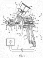
- FIG. 1 is a cross-sectional side view illustrating an embodiment of the spray coating gun assembly 10.
- the spray coating gun assembly includes a spray coating gun 12, an air supply 14, and a gravity fed container assembly 16.
- the spray coating gun 12 includes a spray tip assembly 18 coupled to a body 20.
- the spray tip assembly 18 includes a liquid delivery tip assembly 22, which may be removably inserted into a receptacle 24 of the body 20.
- a plurality of different types of spray coating devices may be configured to receive and use the liquid delivery tip assembly 22.
- the spray tip assembly 18 also includes a spray formation assembly 26 coupled to the liquid delivery tip assembly 22.
- the spray formation assembly 26 may include a variety of spray formation mechanisms, such as air, rotary, and electrostatic atomization mechanisms.
- the illustrated spray formation assembly 26 comprises an air atomization cap 28, which is removably secured to the body 20 via a retaining nut 30.
- the air atomization cap 28 includes a variety of air atomization orifices, such as a central atomization orifice 32 disposed about a liquid tip exit 34 from the liquid delivery tip assembly 22.
- the air atomization cap 28 may also have one or more spray shaping air orifices, such as spray shaping orifices 36, which use air jets to force the spray to form a desired spray pattern (e.g., a flat spray).
- the spray formation assembly 26 may also include a variety of other atomization mechanisms to provide a desired spray pattern and droplet distribution.
- the body 20 of the spray coating gun 12 includes a variety of controls and supply mechanisms for the spray tip assembly 18.
- the body 20 includes a liquid delivery assembly 38 having a liquid passage 40 extending from a liquid inlet coupling 42 to the liquid delivery tip assembly 22.
- the liquid delivery assembly 38 also includes a liquid valve assembly 44 to control liquid flow through the liquid passage 40 and to the liquid delivery tip assembly 22.
- the illustrated liquid valve assembly 44 has a needle valve 46 extending movably through the body 20 between the liquid delivery tip assembly 22 and a liquid valve adjuster 48.
- the liquid valve adjuster 48 is rotatably adjustable against a spring 50 disposed between a rear section 52 of the needle valve 46 and an internal portion 54 of the liquid valve adjuster 48.
- the needle valve 46 is also coupled to a trigger 56, such that the needle valve 46 may be moved inwardly away from the liquid delivery tip assembly 22 as the trigger 56 is rotated counter clockwise about a pivot joint 58.
- a trigger 56 such that the needle valve 46 may be moved inwardly away from the liquid delivery tip assembly 22 as the trigger 56 is rotated counter clockwise about a pivot joint 58.
- any suitable inwardly or outwardly openable valve assembly may be used within the scope of the present technique.
- the liquid valve assembly 44 also may include a variety of packing and seal assemblies, such as packing assembly 60, disposed between the needle valve 46 and the body 20.
- An air supply assembly 62 is also disposed in the body 20 to facilitate atomization at the spray formation assembly 26.
- the illustrated air supply assembly 62 extends from an air inlet coupling 64 to the air atomization cap 28 via air passages 66 and 68.
- the air supply assembly 62 also includes a variety of seal assemblies, air valve assemblies, and air valve adjusters to maintain and regulate the air pressure and flow through the spray coating gun 12.
- the illustrated air supply assembly 62 includes an air valve assembly 70 coupled to the trigger 56, such that rotation of the trigger 56 about the pivot joint 58 opens the air valve assembly 70 to allow air flow from the air passage 66 to the air passage 68.
- the air supply assembly 62 also includes an air valve adjustor 72 to regulate the air flow to the air atomization cap 28.
- the trigger 56 is coupled to both the liquid valve assembly 44 and the air valve assembly 70, such that liquid and air simultaneously flow to the spray tip assembly 18 as the trigger 56 is pulled toward a handle 74 of the body 20.
- the spray coating gun 12 produces an atomized spray with a desired spray pattern and droplet distribution.
- the gravity fed container assembly 16 and the air supply 14 provide a respective liquid coating material and air to the spray coating gun 12.
- the air supply 14 enables the spray coating gun 12 to spray and shape the liquid coating material exiting the gravity fed container assembly 16.
- the air supply 14 couples to the spray gun 12 at air inlet coupling 64 and supplies air via air conduit 76.
- Embodiments of the air supply 14 may include an air compressor, a compressed air tank, a compressed inert gas tank, or a combination thereof.
- the gravity fed container assembly 16 is directly mounted to the spray coating gun 12 to supply a liquid coating material (e.g., a solvent, paint, sealer, stain, etc.) to the spray coating gun 12.
- the illustrated gravity fed container assembly 16 includes a spray coating supply container 78, a lid 80, a filter assembly 82, a valve 84, and an adapter 86.
- all or some of the components in the gravity fed container assembly 16 may be designed for a single use application (i.e., the spray coating supply container 78, the lid 80, the filter assembly 82, and the valve 84).
- the components in the gravity fed container assembly 16 may be made of a disposable and/or recyclable material, such as a transparent or translucent plastic, a fibrous or cellulosic material, a non-metallic material, or some combination thereof.
- the gravity fed container assembly 16 may be made entirely (e.g., 100 percent) or substantially (e.g., greater than 75, 80, 85, 90, 95, 99 percent) from a disposable and/or recyclable material.
- Embodiments of a gravity fed container assembly 16 include a material composition consisting essentially or entirely of a polymer, e.g., polyethylene.
- Embodiments of a fibrous container assembly 140 include a material composition consisting essentially or entirely of natural fibers (e.g., vegetable fibers, wood fibers, animal fibers, or mineral fibers) or synthetic/man-made fibers (e.g., cellulose, mineral, or polymer). Examples of cellulose fibers include modal or bamboo.
- Examples of polymer fibers include nylon, polyester, polyvinyl chloride, polyolefins, aramids, polyethylene, elastomers, and polyurethane.
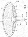
- FIG. 2 is a perspective view of an embodiment of the filter assembly 82 coupled to the valve 84.
- the filter assembly 82 and the valve 84 may be a single component, e.g., integrated together as one-piece. In other embodiments, the filter assembly 82 and the valve 84 may be separate components coupled together for use in the gravity fed container assembly 16.
- the filter assembly 82 includes an outer ring 86, an inner disc 88, support arms 90, and a filter or mesh 92.
- the mesh 92 may have a mesh spacing or opening size of equal, lesser than, or greater than approximately 50, 75, 100, 125, 150, 175, 200, 225, or 250 microns for filtering a liquid coating material exiting the gravity fed container assembly 16.
- the filter or mesh 92 may include a sheet of filter material or screen material, such as a paper filter, a metal or plastic screen, or a membrane sheet.
- the mesh 92 and support arms 90 extend from the outer ring 86 to the inner disc 88.
- the support arms 90 may support the mesh (e.g., one sheet of conical mesh) and/or provide a connection point for different segments of mesh 92 (i.e., mesh segments may stretch between and couple to neighboring support arms 90).
- the arms 90 may be made out of a recyclable material, such as plastic. In the present embodiment, there are three support arms 90, but in other embodiments there may be different numbers of support arms (e.g., 1, 2, 3, 4, 5, etc.).
- the filter assembly 82 couples to the valve 84.
- the valve 84 includes an annular portion 94 and a base portion 96.
- the annular and base portions 94 and 96 may be made of recyclable materials such as plastic.
- the annular portion 94 enables the filter assembly 82 to couple to the valve 84 and to form a seal with the spray coating supply container 78.
- the base portion 96 includes ribs or panels 98 arranged in the form of an "X", e.g., an x-shaped extrusion. As will be explained in more detail below, the "X" shape enables fluid to pass through the valve 84 and into the spray coating gun 12.
- FIG. 3 is a cross-sectional side view of an embodiment of the gravity fed container assembly 16 with the valve 84 in a closed position.
- the gravity fed container assembly 16 includes spray coating supply container 78, lid 80, filter assembly 82, and valve 84.
- the spray coating supply container 78 includes an outer wall 100 and a base 102. Together, the outer wall 100 and base 102 form a chamber 104 that enables the gravity fed container assembly 16 to store a liquid coating material.
- the outer wall 100 includes a rim or ledge 106 (e.g., an annular lip) for attachment of the lid 80, and mixing scales 108 (e.g., volumetric marks or indicators).
- Each mark or scale 108 indicates a volume of liquid in the chamber 104.
- the mixing scales 108 enable a user to pour and measure an amount of liquid coating material(s) into chamber 104.
- the outer wall 100 may be made out of a transparent or translucent material enabling a user to directly measure the liquid coating material(s) in the spray coating supply container 78, saving time and material (i.e., eliminates measurement of liquid coating material in a separate container).
- the mixing scales 108 may use US standard or metric units, (e.g., fluid ounce, pints, cups, liters, milliliters, or any combination thereof).
- the base 102 includes a cone-shaped filter support portion 110 (e.g., base or wall), a valve wall 111, and an adapter connector portion 112 (e.g., adapter receptacle).
- the cone-shaped filter support portion 110 defines an angle 114 with the valve wall 111.
- the angle 114 enables the cone-shaped filter portion 110 to guide liquid coating material towards a valve aperture 116 in the center of the cone-shaped filter portion 110.
- the angle 114 may vary depending on the type of fluid to be sprayed (e.g., approximately 10, 20, 30, 40, or more degrees). For example, the angle 114 may increase for a more viscous liquid coating material to encourage liquid coating material flow towards the valve aperture 116.
- the filter assembly 82 rests on the cone-shaped filter support portion 110 when the valve 84 is in the closed position. With the filter assembly 82 flush with the cone-shaped filter portion 110, a user is able to mix a liquid coating material(s) within the spray coating supply container 78. Accordingly, the gravity fed container assembly 16 saves the user time and material (e.g., eliminates measurement and mixing of liquid coating material(s) in a separate container).
- the base 102 includes an annular valve wall 111.
- the valve wall 111 in combination with the valve 84 control fluid flow out of the spray coating supply container 78. More specifically, the valve wall 111 contacts and creates a sealing engagement with the annular portion 94 when the valve is in the closed position. As will be explained in further detail below, in the open position, the annular portion 94 of the valve 84 disengages from the annular valve wall 111 enabling liquid coating material to flow out of the spray coating supply container 78.
- the adapter connector portion 112 receives the adapter 86 (seen in FIG. 1 ). The adapter 86 opens the valve 84 and couples the spray coating supply container 78 to the spray coating gun 12.
- the adapter connector portion 112 includes an annular wall 118 with a helical or spiral flange 120. The helical flange 120 enables the adapter 86 to couple to the spray coating supply container 78 during operation.
- FIG. 4 is a cross-sectional side view of an embodiment of the gravity fed container assembly 16 in an open position.
- the adapter 86 connects to the spray coating supply container 78 with a body portion 122.
- the body portion 122 includes a helical or spiral groove 124 that rotatingly engages the helical or spiral flange 120 of the annular wall 118.
- the adapter 86 engages the valve 84. More specifically, the adapter 86 engages the valve 84 with a stepped aperture 126.
- the stepped aperture 126 extends through the body portion 122 and a spray gun connector portion 128, enabling liquid coating material to flow from the chamber 104 and into the spray coating gun 12.
- the stepped aperture 126 includes a first counterbore 130 (e.g., cylindrical bore) and a second counterbore 132, (e.g., a cylindrical bore) which have different diameters.
- first counterbore 130 e.g., cylindrical bore
- second counterbore 132 e.g., a cylindrical bore
- the adapter 86 may continue to move in direction 134 until the second counterbore 132 engages the annular valve wall 111, blocking further movement of the adapter 86.
- the valve 84 transitions from a closed position to an open position.
- the filter assembly 82 couples to the valve 84, as the valve 84 opens in direction 134 the valve 84 causes the filter assembly 82 to lift away from the conical-shaped portion 110 of the base 102.
- movement of the valve 84 simultaneously opens the aperture 116 and lifts the filter assembly 82 into a filtering position (e.g., spaced vertically above the support portion 110).
- a filtering position e.g., spaced vertically above the support portion 110.
- liquid coating material 136 is able to pass through the mesh 92, the aperture 116, and into the stepped aperture 126 for use by the spray coating gun 12.
- the outer ring 86 does not move as the valve 84 moves in direction 134.
- the outer ring 86 may couple to the conical shaped portion 110 by press fitting, gluing, spot welding, etc. to prevent vertical movement. Accordingly, as the valve 84 moves in direction 134 the valve 84 moves the support arms 90 and the mesh 92, but not the outer ring 86. Thus, movement of the valve 84 in direction 134 forces the support arms 90 to flex away from the conical-shaped portion 110. The support arms 90 resist movement in direction 134 and therefore provide a biasing force (e.g., a spring biasing force) in direction 138 that forces the valve 84 to close when the spray coating supply container 78 separates from the adapter 86.
- a biasing force e.g., a spring biasing force
- the arms 90 may function as springs (e.g., resilient spring arms) to bias the filter assembly 82 and valve 84 toward the closed position.
- the support arms 90 close the valve 84, the support arms move the mesh 92 into contact with the conical-shaped portion 110.
- the liquid coating material(s) wets the filter assembly 82 (e.g., preventing liquid coating material from drying on the mesh 92 and the valve 84) enabling storage of liquid coating material(s) for later use.
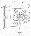
- FIG. 5 is a cross-sectional side view of an embodiment of the gravity fed container assembly 16 in an open position.
- the adapter 86 connects to the spray coating supply container 78 with a body portion 122.
- the body portion 122 includes a helical groove 124 that rotatingly engages the helical flange 120 of the annular wall 118.
- the adapter 86 engages the first counterbore 130 of the stepped aperture 126 forcing the valve 84 upwards in direction 134.
- the adapter 86 may continue to move in direction 134 until the second counterbore 132 engages the annular valve wall 111, blocking further movement of the adapter 86.
- valve 84 transitions from a closed position to an open position. Moreover, because the filter assembly 82 couples to the valve 84, as the valve 84 opens in direction 134, the valve 84 causes the filter assembly 82 to lift away from the conical-shaped portion 110 of the base 102. Thus, movement of the valve 84 simultaneously opens the aperture 116 and lifts the filter assembly 82 into a filtering position. In the filtering position, liquid coating material 136 is able to pass through the mesh 92, the aperture 116, and into the stepped aperture 126 for use by the spray coating gun 12. In the present embodiment, the entire filter assembly 82 moves in direction 134.
- a spring 140 coupled to the filter assembly 82 and to the conical shaped portion 110 biases the valve 84 toward a closed position. More specifically, the spring 140 resist movement of the filter assembly 82 and the valve 84 in direction 134.
- the spring 140 is stretched in tension. Accordingly, after removal of the adapter 86, the spring 140 compresses in direction 138 closing the valve 84 and moving the filter assembly 82 into contact with the conical-shaped portion 110.
- the gravity fed container assembly 16 may not include the spring 140 or other biasing mechanism to bias the valve 84 in a closed position. Accordingly, once the adapter 86 engages the valve 84 and forces the valve 84 in direction 134 there is no biasing force to return it to a closed position.
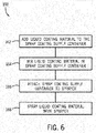
- FIG. 6 is a flow chart illustrating an embodiment of a spray coating process 160 utilizing the gravity fed container assembly of FIG. 1 .
- the process 160 begins by adding liquid coating material to the spray coating supply container 78 (block 162). Specifically, the lid 80 may be removed and a liquid coating material or materials may be poured into chamber 104 of the spray coating supply container 78. As the liquid coating material(s) is added a user may use the mixing scales 108 to measure amounts of liquid coating material(s). After pouring, the liquid coating material(s) are mixed (e.g., stirred in the container 78 or shaken in the container 78 with the lid attached) (block 164).
- the liquid coating material(s) are mixed (e.g., stirred in the container 78 or shaken in the container 78 with the lid attached) (block 164).
- the filter assembly 82 rests on the base 102 enabling a user to mix the liquid spraying material in the spray coating supply container 78 (e.g., a user does not need to pour and mix the liquid spraying material in a separate container before adding it to the spray coating supply container 78).
- the spray coating supply container 78 is attached to the sprayer 12 (block 166). A user may then spray liquid coating material with the sprayer 12 (block 168).
Landscapes
- Nozzles (AREA)
- Containers And Packaging Bodies Having A Special Means To Remove Contents (AREA)
- Details Or Accessories Of Spraying Plant Or Apparatus (AREA)
Applications Claiming Priority (3)
| Application Number | Priority Date | Filing Date | Title |
|---|---|---|---|
| US201361755410P | 2013-01-22 | 2013-01-22 | |
| US14/146,617 US9352343B2 (en) | 2013-01-22 | 2014-01-02 | Liquid supply system for a gravity feed spray device |
| EP14701258.7A EP2948254B1 (en) | 2013-01-22 | 2014-01-08 | Valve and filter system for a gravity feed spray container |
Related Parent Applications (2)
| Application Number | Title | Priority Date | Filing Date |
|---|---|---|---|
| EP14701258.7A Division EP2948254B1 (en) | 2013-01-22 | 2014-01-08 | Valve and filter system for a gravity feed spray container |
| EP14701258.7A Division-Into EP2948254B1 (en) | 2013-01-22 | 2014-01-08 | Valve and filter system for a gravity feed spray container |
Publications (1)
| Publication Number | Publication Date |
|---|---|
| EP3053656A1 true EP3053656A1 (en) | 2016-08-10 |
Family
ID=51206972
Family Applications (2)
| Application Number | Title | Priority Date | Filing Date |
|---|---|---|---|
| EP16161559.6A Withdrawn EP3053656A1 (en) | 2013-01-22 | 2014-01-08 | Liquid supply system for a gravity feed spray device |
| EP14701258.7A Active EP2948254B1 (en) | 2013-01-22 | 2014-01-08 | Valve and filter system for a gravity feed spray container |
Family Applications After (1)
| Application Number | Title | Priority Date | Filing Date |
|---|---|---|---|
| EP14701258.7A Active EP2948254B1 (en) | 2013-01-22 | 2014-01-08 | Valve and filter system for a gravity feed spray container |
Country Status (11)
| Country | Link |
|---|---|
| US (2) | US9352343B2 (enExample) |
| EP (2) | EP3053656A1 (enExample) |
| JP (2) | JP6199996B2 (enExample) |
| CN (2) | CN105050726B (enExample) |
| AR (1) | AR094549A1 (enExample) |
| AU (2) | AU2014209781C1 (enExample) |
| BR (1) | BR112015017379A2 (enExample) |
| CA (1) | CA2898179C (enExample) |
| ES (1) | ES2719053T3 (enExample) |
| TW (1) | TW201436866A (enExample) |
| WO (1) | WO2014116428A1 (enExample) |
Cited By (1)
| Publication number | Priority date | Publication date | Assignee | Title |
|---|---|---|---|---|
| DE102020109913A1 (de) | 2020-04-08 | 2021-10-14 | Sata Gmbh & Co. Kg | Farbbecher aus natürlichem Faserstoff |
Families Citing this family (23)
| Publication number | Priority date | Publication date | Assignee | Title |
|---|---|---|---|---|
| WO2015084617A1 (en) | 2013-12-05 | 2015-06-11 | 3M Innovative Properties Company | Container for a spraying device |
| US10589309B2 (en) | 2015-02-20 | 2020-03-17 | Carlisle Fluid Technologies, Inc. | Sprayer adapter |
| EP3319733B1 (en) * | 2015-07-08 | 2020-11-11 | 3M Innovative Properties Company | Spray gun cups, receptacles, and methods of use |
| USD811525S1 (en) * | 2016-03-24 | 2018-02-27 | 3M Innovative Properties Company | Retention collar for spray gun cup |
| AU2017207361B2 (en) | 2016-01-15 | 2019-10-31 | 3M Innovative Properties Company | Connector system for hand-held spray guns |
| US10689165B2 (en) | 2016-01-15 | 2020-06-23 | 3M Innovative Properties Company | Reservoir systems for hand-held spray guns and methods of use |
| CN108472667A (zh) | 2016-01-15 | 2018-08-31 | 3M创新有限公司 | 模块化喷枪封盖组件以及设计和使用的方法 |
| USD793530S1 (en) * | 2016-03-24 | 2017-08-01 | 3M Innovative Properties Company | Lid for spray gun cup |
| EP3402603B1 (en) * | 2016-01-15 | 2023-05-24 | 3M Innovative Properties Company | Spray gun cups, receptacles, and methods of use |
| PL3402604T3 (pl) | 2016-01-15 | 2021-07-19 | 3M Innovative Properties Company | Złącze z szerokim otworem dla cieczy do ręcznych pistoletów natryskowych |
| EP3402602B2 (en) | 2016-01-15 | 2025-04-16 | 3M Innovative Properties Company | Spray gun cups, receptacles, lids, and methods of use |
| US20170239679A1 (en) * | 2016-02-23 | 2017-08-24 | Carlisle Fluid Technologies, Inc. | System and method having filter disposed in fluid supply cup |
| DE202016004642U1 (de) * | 2016-07-28 | 2016-11-15 | Sata Gmbh & Co. Kg | Materialbehälter für ein zu verspritzendes Material |
| JP2020513312A (ja) * | 2016-12-12 | 2020-05-14 | スリーエム イノベイティブ プロパティズ カンパニー | ハンドヘルドスプレーガンのための貯蔵容器システム |
| US11826766B2 (en) * | 2018-03-19 | 2023-11-28 | Wagner Spray Tech Corporation | Handheld fluid sprayer |
| CN117547720A (zh) * | 2018-10-02 | 2024-02-13 | 波士顿科学国际有限公司 | 用于流体化和输送粉状剂的装置 |
| AU2019352968B2 (en) | 2018-10-02 | 2024-10-31 | Boston Scientific Scimed, Inc. | Devices for fluidization and delivering a powdered agent |
| US20220023895A1 (en) * | 2018-12-21 | 2022-01-27 | J. Wagner Gmbh | Fluid tank having storage medium and valve system for an electrodynamic atomizer and atomizer and method for operating the atomizer |
| CN109985745B (zh) * | 2019-04-10 | 2020-07-28 | 业成科技(成都)有限公司 | 可提高曲面喷涂均匀性之喷涂装置 |
| CN110947548A (zh) * | 2019-11-12 | 2020-04-03 | 清远市叶氏涂装产业科技有限公司 | 一种水性油漆喷枪及其喷涂方法 |
| USD952097S1 (en) * | 2020-07-14 | 2022-05-17 | Yuyao Yufeng Scutcheon Plastic Factory | Paint spraying pot lid |
| KR20230073246A (ko) * | 2020-09-21 | 2023-05-25 | 보스톤 싸이엔티픽 싸이메드 인코포레이티드 | 의료 장치용 압력 밸브 |
| US20240286156A1 (en) * | 2023-02-23 | 2024-08-29 | Bmic Llc | Spray application system and methods of use thereof |
Citations (3)
| Publication number | Priority date | Publication date | Assignee | Title |
|---|---|---|---|---|
| WO2003095101A1 (en) * | 2002-05-08 | 2003-11-20 | 3M Innovative Properties Company | Valve closure for spray gun reservoir |
| WO2004037431A1 (en) * | 2002-10-24 | 2004-05-06 | 3M Innovative Properties Company | Spray gun with pressure assisted liquid supply cup comprising an inner liner |
| WO2012154619A2 (en) * | 2011-05-06 | 2012-11-15 | Saint-Gobain Abrasives, Inc. | Multi-seal paint cup assembly |
Family Cites Families (83)
| Publication number | Priority date | Publication date | Assignee | Title |
|---|---|---|---|---|
| US1824017A (en) | 1929-07-18 | 1931-09-22 | Binks Mfg Co | Touch-up spray gun |
| US1837844A (en) | 1930-04-21 | 1931-12-22 | Binks Mfg Co | All metal sealing cap for paint containers |
| US1944920A (en) | 1931-08-26 | 1934-01-30 | Binks Mfg Co | Pressure-cup for spray appliances |
| US2263842A (en) | 1937-09-03 | 1941-11-25 | Binks Mfg Co | Means for connecting containers to spraying devices |
| US2934246A (en) | 1953-05-25 | 1960-04-26 | Sharpe Mfg Co | Paint spray gun |
| US3136486A (en) | 1962-06-21 | 1964-06-09 | Melford H Docken | Spray gun for use with a disposable container |
| US3157360A (en) | 1963-02-25 | 1964-11-17 | William L Heard | Spray gun having valved flexible liner |
| US3240398A (en) | 1964-03-09 | 1966-03-15 | Sharpe Mfg Company | Vented spray gun cup |
| US3334860A (en) * | 1964-07-13 | 1967-08-08 | Jr Cecil G Bolton | Fluid coupling |
| FR1483766A (fr) | 1966-02-07 | 1967-06-09 | Micro Mega Sa | Dispositif d'accrochage d'une pièce à main dentaire |
| US3714967A (en) | 1971-05-14 | 1973-02-06 | Stewart Warner Corp | Siphon paint spray cup assembly |
| US3893627A (en) | 1974-08-29 | 1975-07-08 | Graco Inc | Electric airless cup gun apparatus |
| US3990609A (en) | 1976-03-12 | 1976-11-09 | Champion Spark Plug Company | Attachment for paint spray gun systems |
| US4174070A (en) | 1976-11-08 | 1979-11-13 | Binks Manufacturing Company | Spray gun assembly |
| US4174071A (en) | 1976-11-08 | 1979-11-13 | Binks Manufacturing Company | Spray gun assembly |
| US4184778A (en) | 1979-03-12 | 1980-01-22 | Terrels Joseph L | Cup for paint sprayer |
| US4433812A (en) | 1980-11-12 | 1984-02-28 | Champion Spark Plug Company | Paint spray attachment |
| US4730753A (en) | 1982-12-27 | 1988-03-15 | Champion Spark Plug Company | Paint cup vent |
| GB8324265D0 (en) | 1983-09-09 | 1983-10-12 | Devilbiss Co | Miniature spray guns |
| DE3346165C2 (de) * | 1983-12-21 | 1987-04-30 | Hartmut 2905 Edewecht Ihmels | Sprühmitteleinsatz für Sprühpistolen |
| US4501500A (en) | 1984-01-20 | 1985-02-26 | Terrels Joseph L | Paint cup for sprayer |
| CN85101088A (zh) * | 1985-04-01 | 1987-01-24 | 海因里希·艾梅尔斯;哈特马特·艾梅尔特 | 喷枪喷雾剂导入件及适用此类导入件的喷枪 |
| US4760962A (en) | 1987-10-30 | 1988-08-02 | The Devilbiss Company | Spray gun paint cup and lid assembly |
| US4832232A (en) | 1988-04-08 | 1989-05-23 | Broccoli Anthony B | Spray gun vent |
| US4948042A (en) | 1989-07-21 | 1990-08-14 | Tench Rex D | Compressed air spray gun adapted for use with more than one canister |
| US5054687A (en) | 1990-03-14 | 1991-10-08 | Ransburg Corporation | Pressure feed paint cup |
| US5052623A (en) | 1990-09-10 | 1991-10-01 | Nordeen Melvin A | Compartmentalized paint cup with selector valve for spray guns |
| US5119992A (en) | 1991-02-11 | 1992-06-09 | Ransburg Corporation | Spray gun with regulated pressure feed paint cup |
| US5067518A (en) | 1991-05-01 | 1991-11-26 | Ransburg Corporation | Pressure feed paint cup valve |
| US5209365A (en) | 1992-09-01 | 1993-05-11 | Devilbiss Air Power Company | Paint cup lid assembly |
| US5307994A (en) | 1993-06-04 | 1994-05-03 | Hieronymus John R | Dripless spray gun vent and reservoir assembly for syphon-cup paint spray gun |
| JPH07232728A (ja) * | 1994-02-16 | 1995-09-05 | Toppan Printing Co Ltd | 倒立容器用注出装置 |
| CA2143277C (en) | 1994-04-19 | 2000-05-16 | Michael J. Kosmyna | Hand held paint spray gun with top mounted paint cup |
| US5667142A (en) | 1995-05-30 | 1997-09-16 | Newstripe, Inc. | Spray gun with removable supply line |
| US5573516A (en) * | 1995-09-18 | 1996-11-12 | Medical Connexions, Inc. | Needleless connector |
| US5803360A (en) | 1995-11-27 | 1998-09-08 | Spitznagel; Max W. A. | Apparatus for providing enhanced spray capabilities for a gravity-fed spray gun |
| US7080653B2 (en) | 1996-09-20 | 2006-07-25 | Patent Category Corp. | Collapsible storage devices |
| US6820824B1 (en) | 1998-01-14 | 2004-11-23 | 3M Innovative Properties Company | Apparatus for spraying liquids, disposable containers and liners suitable for use therewith |
| ES2278100T3 (es) * | 1997-01-24 | 2007-08-01 | 3M Company | Aparato para pulverizar liquidos y recipientes y revestimientos desechables adecuados para usar con el mismo. |
| US5853102A (en) | 1997-01-27 | 1998-12-29 | Jarrett; Guy R. | Insert for spray gun paint cups |
| US5810258A (en) | 1997-09-30 | 1998-09-22 | Wu; Yu-Chin | Paint cup mounting arrangements of a paint spray gun |
| US5918815A (en) | 1997-10-22 | 1999-07-06 | Wu; Yu-Chih | Paint cup mounting arrangement of a paint spray gun |
| NL1007944C2 (nl) | 1997-12-31 | 1999-07-01 | Hadewe Bv | Registratie van documenten. |
| US6012651A (en) | 1998-04-10 | 2000-01-11 | Spitznagel; Max W. A. | Gravity-fed spray gun assembly |
| DE29909950U1 (de) | 1999-06-08 | 1999-09-23 | Chang, Jen-Chih, Taichung | Spritzpistolenbehälter |
| US6536687B1 (en) | 1999-08-16 | 2003-03-25 | 3M Innovative Properties Company | Mixing cup adapting assembly |
| US6189809B1 (en) | 1999-09-23 | 2001-02-20 | Illinois Tool Works Inc. | Multi-feed spray gun |
| US7188785B2 (en) | 2001-04-24 | 2007-03-13 | 3M Innovative Properties Company | Reservoir with refill inlet for hand-held spray guns |
| US6588681B2 (en) | 2001-07-09 | 2003-07-08 | 3M Innovative Properties Company | Liquid supply assembly |
| US6752179B1 (en) | 2002-03-28 | 2004-06-22 | 3M Innovative Properties Company | Small liquid supply assembly |
| GB0210446D0 (en) | 2002-05-08 | 2002-06-12 | 3M Innovative Properties Co | Conformable pouch reservoir for spray gun |
| GB0224698D0 (en) | 2002-10-24 | 2002-12-04 | 3M Innovative Properties Co | Easy clean spray gun |
| US7845582B2 (en) | 2002-12-18 | 2010-12-07 | 3M Innovative Properties Company | Spray gun reservoir with oversize, fast-fill opening |
| GB0307902D0 (en) | 2003-04-05 | 2003-05-14 | 3M Innovative Properties Co | Spray gun with rotatable reservoir |
| US6796514B1 (en) | 2003-05-02 | 2004-09-28 | 3M Innovative Properties Company | Pre-packaged material supply assembly |
| US6945429B2 (en) | 2003-06-10 | 2005-09-20 | Illinois Tool Works Inc. | Disposable paint cup attachment system for gravity-feed paint sprayer |
| FR2859118B1 (fr) | 2003-08-26 | 2007-03-09 | Michel Camilleri | Godet jetable a monter sur un pistolet pour la preparation, l'application et la conservation d'une peinture |
| US7083119B2 (en) | 2003-09-25 | 2006-08-01 | 3M Innovative Properties Company | Security clip for spray gun connector |
| US7380680B2 (en) | 2004-01-16 | 2008-06-03 | Illinois Tool Works Inc. | Fluid supply assembly |
| US7665672B2 (en) * | 2004-01-16 | 2010-02-23 | Illinois Tool Works Inc. | Antistatic paint cup |
| US7086549B2 (en) | 2004-01-16 | 2006-08-08 | Illinois Tool Works Inc. | Fluid supply assembly |
| US7165732B2 (en) * | 2004-01-16 | 2007-01-23 | Illinois Tool Works Inc. | Adapter assembly for a fluid supply assembly |
| US7373111B2 (en) | 2004-02-19 | 2008-05-13 | Marvell International Ltd. | Communication access apparatus, systems, and methods |
| US7568638B2 (en) | 2004-04-29 | 2009-08-04 | Sata Gmbh & Co. Kg | Ventilated gravity cup for a paint spray gun |
| US7766250B2 (en) * | 2004-06-01 | 2010-08-03 | Illinois Tool Works Inc. | Antistatic paint cup |
| US7757972B2 (en) | 2004-06-03 | 2010-07-20 | Illinois Tool Works Inc. | Conversion adapter for a fluid supply assembly |
| US7354074B2 (en) | 2004-06-03 | 2008-04-08 | Illinois Tool Works Inc. | Adapter assembly for a fluid supply assembly |
| US7353964B2 (en) | 2004-06-10 | 2008-04-08 | Illinois Tool Works Inc. | Fluid supply assembly |
| US20060049099A1 (en) | 2004-09-03 | 2006-03-09 | Chang Jen C | Filter device used in a paint cup of a spraying gun |
| DE102004043599B4 (de) | 2004-09-07 | 2014-11-27 | Sata Gmbh & Co. Kg | Fließbecher für eine Farbspritzpistole |
| KR101215361B1 (ko) | 2004-09-15 | 2012-12-26 | 에이전시 포 사이언스, 테크놀로지 앤드 리서치 | 전사된 폴리머 지지체 |
| US20060102550A1 (en) | 2004-11-18 | 2006-05-18 | Joseph Stephen C P | Liquid supply and filter assembly |
| PT1835997E (pt) | 2004-12-16 | 2012-09-17 | Saint Gobain Abrasifs Sa | Copo de abastecimento de líquidos e conjunto de revestimento para pistolas pulverizadoras |
| US7175110B2 (en) | 2004-12-21 | 2007-02-13 | Anest Iwata Corporation | Manual spray gun and associated disposable cup |
| WO2006079981A2 (en) | 2005-01-31 | 2006-08-03 | Illinois Tool Works Inc. | Fluid supply assembly with measuring guide |
| US7891588B2 (en) | 2006-05-31 | 2011-02-22 | Wagner Spray Tech Corporation | Quick disconnect for wetted parts in a paint spray gun |
| EP2564937B1 (en) | 2006-06-20 | 2017-04-12 | Saint-Gobain Abrasives, Inc. | Liquid supply assembly |
| US8437397B2 (en) | 2007-01-04 | 2013-05-07 | Qualcomm Incorporated | Block information adjustment techniques to reduce artifacts in interpolated video frames |
| GB0702398D0 (en) * | 2007-02-08 | 2007-03-21 | Leafgreen Ltd | A valve for a pressurised dispenser and a pressurised dispenser containing such a valve |
| DE202007011604U1 (de) | 2007-08-18 | 2009-01-02 | Sata Gmbh & Co. Kg | Anschlussteil zur Verbindung einer Materialzuführungseinrichtung an eine Spritzpistole |
| US7815132B2 (en) | 2008-08-12 | 2010-10-19 | Illinois Tool Works Inc. | Method for preventing voltage from escaping fluid interface for water base gravity feed applicators |
| US8514295B2 (en) * | 2010-12-17 | 2013-08-20 | Qualcomm Incorporated | Augmented reality processing based on eye capture in handheld device |
| CA2835088C (en) * | 2011-05-06 | 2018-01-16 | Saint-Gobain Abrasives, Inc. | Paint cup assembly with an extended ring |
-
2014
- 2014-01-02 US US14/146,617 patent/US9352343B2/en not_active Expired - Fee Related
- 2014-01-08 CA CA2898179A patent/CA2898179C/en not_active Expired - Fee Related
- 2014-01-08 EP EP16161559.6A patent/EP3053656A1/en not_active Withdrawn
- 2014-01-08 JP JP2015553757A patent/JP6199996B2/ja not_active Expired - Fee Related
- 2014-01-08 WO PCT/US2014/010730 patent/WO2014116428A1/en not_active Ceased
- 2014-01-08 CN CN201480017024.6A patent/CN105050726B/zh not_active Expired - Fee Related
- 2014-01-08 AU AU2014209781A patent/AU2014209781C1/en not_active Ceased
- 2014-01-08 ES ES14701258T patent/ES2719053T3/es active Active
- 2014-01-08 EP EP14701258.7A patent/EP2948254B1/en active Active
- 2014-01-08 BR BR112015017379A patent/BR112015017379A2/pt not_active Application Discontinuation
- 2014-01-08 CN CN201810174469.5A patent/CN108284011A/zh active Pending
- 2014-01-22 AR ARP140100192A patent/AR094549A1/es unknown
- 2014-01-22 TW TW103102307A patent/TW201436866A/zh unknown
-
2016
- 2016-05-26 US US15/166,106 patent/US20160271632A1/en not_active Abandoned
- 2016-10-27 AU AU2016250424A patent/AU2016250424B2/en not_active Ceased
-
2017
- 2017-08-24 JP JP2017161124A patent/JP6553690B2/ja not_active Expired - Fee Related
Patent Citations (3)
| Publication number | Priority date | Publication date | Assignee | Title |
|---|---|---|---|---|
| WO2003095101A1 (en) * | 2002-05-08 | 2003-11-20 | 3M Innovative Properties Company | Valve closure for spray gun reservoir |
| WO2004037431A1 (en) * | 2002-10-24 | 2004-05-06 | 3M Innovative Properties Company | Spray gun with pressure assisted liquid supply cup comprising an inner liner |
| WO2012154619A2 (en) * | 2011-05-06 | 2012-11-15 | Saint-Gobain Abrasives, Inc. | Multi-seal paint cup assembly |
Cited By (1)
| Publication number | Priority date | Publication date | Assignee | Title |
|---|---|---|---|---|
| DE102020109913A1 (de) | 2020-04-08 | 2021-10-14 | Sata Gmbh & Co. Kg | Farbbecher aus natürlichem Faserstoff |
Also Published As
| Publication number | Publication date |
|---|---|
| AU2016250424A1 (en) | 2016-11-17 |
| EP2948254A1 (en) | 2015-12-02 |
| JP6199996B2 (ja) | 2017-09-20 |
| CN105050726A (zh) | 2015-11-11 |
| JP6553690B2 (ja) | 2019-07-31 |
| CA2898179C (en) | 2019-03-26 |
| AU2014209781B2 (en) | 2016-07-28 |
| US20160271632A1 (en) | 2016-09-22 |
| WO2014116428A1 (en) | 2014-07-31 |
| AU2014209781C1 (en) | 2017-03-23 |
| AU2014209781A1 (en) | 2015-08-13 |
| US9352343B2 (en) | 2016-05-31 |
| EP2948254B1 (en) | 2019-03-13 |
| AR094549A1 (es) | 2015-08-12 |
| JP2018001162A (ja) | 2018-01-11 |
| JP2016506865A (ja) | 2016-03-07 |
| ES2719053T3 (es) | 2019-07-08 |
| TW201436866A (zh) | 2014-10-01 |
| AU2016250424B2 (en) | 2018-04-19 |
| CN105050726B (zh) | 2018-04-06 |
| BR112015017379A2 (pt) | 2017-07-11 |
| CA2898179A1 (en) | 2014-07-31 |
| US20140203098A1 (en) | 2014-07-24 |
| CN108284011A (zh) | 2018-07-17 |
Similar Documents
| Publication | Publication Date | Title |
|---|---|---|
| AU2016250424B2 (en) | Liquid supply system for a gravity feed spray device | |
| CN102802807B (zh) | 用于重力馈送喷雾装置的流体供应系统 | |
| AU2011279387B2 (en) | System comprising a spray coating device with a liquid supply container | |
| EP1703989B1 (en) | Bayonet type adapter assembly for the supply cup of a spray gun | |
| MXPA04005599A (es) | Sistema de acoplamiento de cubeta de pintura desechable para aspersor de pintura alimentado por gravedad. | |
| US20170239679A1 (en) | System and method having filter disposed in fluid supply cup | |
| HK1185581A (en) | Liquid supply container for a spray coating device | |
| AU2015201231A1 (en) | System comprising a spray coating device with a liquid supply container |
Legal Events
| Date | Code | Title | Description |
|---|---|---|---|
| PUAI | Public reference made under article 153(3) epc to a published international application that has entered the european phase |
Free format text: ORIGINAL CODE: 0009012 |
|
| AC | Divisional application: reference to earlier application |
Ref document number: 2948254 Country of ref document: EP Kind code of ref document: P |
|
| AK | Designated contracting states |
Kind code of ref document: A1 Designated state(s): AL AT BE BG CH CY CZ DE DK EE ES FI FR GB GR HR HU IE IS IT LI LT LU LV MC MK MT NL NO PL PT RO RS SE SI SK SM TR |
|
| 17P | Request for examination filed |
Effective date: 20170209 |
|
| RBV | Designated contracting states (corrected) |
Designated state(s): AL AT BE BG CH CY CZ DE DK EE ES FI FR GB GR HR HU IE IS IT LI LT LU LV MC MK MT NL NO PL PT RO RS SE SI SK SM TR |
|
| 17Q | First examination report despatched |
Effective date: 20181018 |
|
| RIC1 | Information provided on ipc code assigned before grant |
Ipc: B05B 7/24 20060101AFI20191009BHEP Ipc: B05B 7/08 20060101ALI20191009BHEP Ipc: B05B 15/40 20180101ALI20191009BHEP |
|
| GRAP | Despatch of communication of intention to grant a patent |
Free format text: ORIGINAL CODE: EPIDOSNIGR1 |
|
| INTG | Intention to grant announced |
Effective date: 20191120 |
|
| STAA | Information on the status of an ep patent application or granted ep patent |
Free format text: STATUS: THE APPLICATION IS DEEMED TO BE WITHDRAWN |
|
| 18D | Application deemed to be withdrawn |
Effective date: 20200603 |