EP3052993B1 - Clockwork movement and timepiece including such a movement - Google Patents
Clockwork movement and timepiece including such a movement Download PDFInfo
- Publication number
- EP3052993B1 EP3052993B1 EP14765905.6A EP14765905A EP3052993B1 EP 3052993 B1 EP3052993 B1 EP 3052993B1 EP 14765905 A EP14765905 A EP 14765905A EP 3052993 B1 EP3052993 B1 EP 3052993B1
- Authority
- EP
- European Patent Office
- Prior art keywords
- wheel
- differential gear
- spring
- organ
- escapement
- Prior art date
- Legal status (The legal status is an assumption and is not a legal conclusion. Google has not performed a legal analysis and makes no representation as to the accuracy of the status listed.)
- Active
Links
- 230000033001 locomotion Effects 0.000 title claims description 28
- 230000005540 biological transmission Effects 0.000 claims description 36
- 230000001105 regulatory effect Effects 0.000 claims description 25
- 210000000056 organ Anatomy 0.000 claims description 20
- 238000010276 construction Methods 0.000 description 3
- 230000000694 effects Effects 0.000 description 2
- 230000001627 detrimental effect Effects 0.000 description 1
- SYHGEUNFJIGTRX-UHFFFAOYSA-N methylenedioxypyrovalerone Chemical compound C=1C=C2OCOC2=CC=1C(=O)C(CCC)N1CCCC1 SYHGEUNFJIGTRX-UHFFFAOYSA-N 0.000 description 1
- 230000035484 reaction time Effects 0.000 description 1
- 230000003797 telogen phase Effects 0.000 description 1
Images
Classifications
-
- G—PHYSICS
- G04—HOROLOGY
- G04B—MECHANICALLY-DRIVEN CLOCKS OR WATCHES; MECHANICAL PARTS OF CLOCKS OR WATCHES IN GENERAL; TIME PIECES USING THE POSITION OF THE SUN, MOON OR STARS
- G04B15/00—Escapements
- G04B15/14—Component parts or constructional details, e.g. construction of the lever or the escape wheel
-
- G—PHYSICS
- G04—HOROLOGY
- G04B—MECHANICALLY-DRIVEN CLOCKS OR WATCHES; MECHANICAL PARTS OF CLOCKS OR WATCHES IN GENERAL; TIME PIECES USING THE POSITION OF THE SUN, MOON OR STARS
- G04B13/00—Gearwork
- G04B13/007—Gearwork with differential work
- G04B13/008—Differentials
-
- G—PHYSICS
- G04—HOROLOGY
- G04B—MECHANICALLY-DRIVEN CLOCKS OR WATCHES; MECHANICAL PARTS OF CLOCKS OR WATCHES IN GENERAL; TIME PIECES USING THE POSITION OF THE SUN, MOON OR STARS
- G04B1/00—Driving mechanisms
- G04B1/10—Driving mechanisms with mainspring
- G04B1/16—Barrels; Arbors; Barrel axles
-
- G—PHYSICS
- G04—HOROLOGY
- G04B—MECHANICALLY-DRIVEN CLOCKS OR WATCHES; MECHANICAL PARTS OF CLOCKS OR WATCHES IN GENERAL; TIME PIECES USING THE POSITION OF THE SUN, MOON OR STARS
- G04B1/00—Driving mechanisms
- G04B1/10—Driving mechanisms with mainspring
- G04B1/22—Compensation of changes in the motive power of the mainspring
- G04B1/225—Compensation of changes in the motive power of the mainspring with the aid of an interposed power-accumulator (secondary spring) which is always tensioned
-
- G—PHYSICS
- G04—HOROLOGY
- G04B—MECHANICALLY-DRIVEN CLOCKS OR WATCHES; MECHANICAL PARTS OF CLOCKS OR WATCHES IN GENERAL; TIME PIECES USING THE POSITION OF THE SUN, MOON OR STARS
- G04B13/00—Gearwork
- G04B13/02—Wheels; Pinions; Spindles; Pivots
- G04B13/028—Wheels; Pinions; Spindles; Pivots wheels in which the teeth are conic, contrate, etc; also column wheels construction
-
- G—PHYSICS
- G04—HOROLOGY
- G04B—MECHANICALLY-DRIVEN CLOCKS OR WATCHES; MECHANICAL PARTS OF CLOCKS OR WATCHES IN GENERAL; TIME PIECES USING THE POSITION OF THE SUN, MOON OR STARS
- G04B15/00—Escapements
-
- G—PHYSICS
- G04—HOROLOGY
- G04B—MECHANICALLY-DRIVEN CLOCKS OR WATCHES; MECHANICAL PARTS OF CLOCKS OR WATCHES IN GENERAL; TIME PIECES USING THE POSITION OF THE SUN, MOON OR STARS
- G04B17/00—Mechanisms for stabilising frequency
- G04B17/20—Compensation of mechanisms for stabilising frequency
- G04B17/26—Compensation of mechanisms for stabilising frequency for the effect of variations of the impulses
-
- G—PHYSICS
- G04—HOROLOGY
- G04B—MECHANICALLY-DRIVEN CLOCKS OR WATCHES; MECHANICAL PARTS OF CLOCKS OR WATCHES IN GENERAL; TIME PIECES USING THE POSITION OF THE SUN, MOON OR STARS
- G04B17/00—Mechanisms for stabilising frequency
- G04B17/32—Component parts or constructional details, e.g. collet, stud, virole or piton
Definitions
- the present invention also relates to a timepiece comprising such a movement.
- An object of the present invention is therefore to overcome this disadvantage, by providing a clockwork to provide immediately to each of the two regulating organs energy that is necessary without disturbing the other regulating organ.
- the spring members make it possible to immediately supply each of the two regulating members the necessary energy without disturbing the other regulating organ by eliminating the losses or surplus energy due to the differential gears known from the prior art.
- the differential gear may comprise a first transmission wheel and a first output wheel rotatably mounted and kinematically connected to the first assembly, said first spring member having a first end connected to said first output wheel and a second end. connected to said first transmission wheel.
- the differential gear may comprise a second transmission wheel and a second output wheel rotatably mounted and kinematically connected to the second assembly, said second spring member having a first end connected to said second output wheel and a second end. connected to said second transmission wheel.
- the first resetting means of the first spring member may comprise a first drive means of the first output wheel, said first drive means being integral with the first transmission wheel.
- the second resetting means of the second spring member may comprise a second drive means of the second output wheel, said second drive means being integral with the second transmission wheel.
- the differential gear may comprise an input wheel kinematically connected to the power source.
- the input wheel may carry at least one pinion-satellite arranged to cooperate with each of the first and second transmission wheels.
- each of the first and second spring members may be a spiral spring.
- the present invention also relates to a timepiece comprising a movement as defined above.
- the regulating members 2 and 10 are simple pendulums, but it is obvious that they can also be whirlpools or carousels.
- the first and second exhausts shown are Swiss-anchored but they could be of another type, such as escapements or relaxation other known exhaust types.
- the components of the differential gear are pivotally mounted around a shaft 20 integral with the movement frame.
- the differential gear 18 comprises an input wheel 22 pivotally mounted around the shaft 20 and having an external toothing meshing with a gear 24 meshing itself with the energy source 1. It is obvious that the mechanism can comprise other mobiles than the return 24 between the differential gear 18 and the energy source 1.
- the input wheel 22 is integral with a planet carrier 26 which comprises shafts 28 perpendicular to the shaft 20 and on each of which is pivotally mounted a planet gear 30.
- the planet gears 30 are with conical teeth.
- the differential gear 18 also includes a first transmission wheel 32 and a second transmission wheel 34, respectively pivotally mounted about the shaft 20 by means of a barrel 33 and 35 respectively.
- Each of the first and second transmission wheels 32, 34 has a conical toothing arranged on either side of the planet gears 30.
- the conical teeth of the first and second transmission wheels 32, 34 are chosen so that they mesh with the conical teeth of the planet gears 30.
- the first and second transmission wheels 32, 34 shown here are in the form of a bell-wheel, but it is obvious that any transmission wheel of a flat differential may be suitable.
- the shape of the gears of the planet gears and the teeth of the transmission wheels are adapted to the construction of the differential. In particular, the teeth can be straight.
- the differential gear 18 also comprises a first output wheel 36 and a second output wheel 38, respectively rotatably mounted around the shaft 20, and disposed outside the first and second transmission wheels 32, 34 respectively .
- the first output wheel 36 has an external toothing meshing with the first gear 8 and the second output wheel 38 has an external toothing meshing with the second gear 16.
- a first pin 40 is driven into the first transmission wheel 32 and inserted with play into a hole provided in the first output wheel 36.
- a second pin 42 is driven into the second transmission wheel 34 and inserted with play in a hole provided in the second output wheel 38. The role of these pins 40, 42 will be described below.
- the first spring member 44 is placed outside the first output wheel 36, opposite the first transmission wheel 32, concentrically to the shaft 20. It has a first end 48 integral with the first output wheel 36 by means of a pin 50 and a second end 52 secured to the barrel 33 of the first transmission wheel 32.
- the second spring member 46 is placed outside the second output wheel 38, opposite the second transmission wheel 34, concentrically to the shaft 20. It has a first end 54 integral with the second output wheel 38 by means of a pin 56 and a second end 58 secured to the barrel 35 of the second transmission wheel 34.
- Pre-arming of the first and second spring members may be provided during movement construction.
- first spring member 44 can be placed inside the first output wheel 36, the same side as the first transmission wheel 32, and the second spring member 46 can be placed inside the second output wheel 38 on the same side as the second transmission wheel 34.
- the spring members 44 and 46 are spiral springs.
- the spring members or elastic members may be of any type of shape (coil, spiral, leaf spring, etc.), and any material, the shape and the material being chosen so that said springs or elastic members can store and to restore energy.
- the driving force arriving from the energy source 1 enters the differential gear 18 by the gearbox 24, the input wheel 22 and the planet carrier 26 which carries the planet gears 30.
- the associated output wheels 36 and 38 respectively transmit a torque to their associated gear train 8 and 16 respectively.
- the spring members 44 and 46 are pre-armed on their associated output wheel 36 and 38 respectively, the latter will turn as soon as they have the possibility.
- the output wheels 36 and 38 will set in motion before the transmission wheels 32 and 34. In fact, the output wheels 36 and 38 are closer to the exhausts 4 and 12 than the transmission wheels 32 and 34. Thus, the force path to be traveled is less important to reach the output wheels 36 and 38, they have a reaction time faster than the transmission wheels 32 and 34.
- This mechanism makes it possible to transmit to the output wheels 36 and 38 forces that come exclusively from their respective spring members 44 and 46. This transmission also occurs when the pulses of the regulating members 2 and 10 are simultaneous.
- each regulating organ 2 and 10 instantaneously receives the energy it needs without disturbing the other.
- all the undesirable effects encountered with the differential gears known from the prior art are eliminated, even when the pulses are simultaneous.
- the first and second transmission wheels 32, 34 In order to allow the rearming of their associated spring member 44, 46, the first and second transmission wheels 32, 34, driven by the energy source 1, will catch their respective offsets relative to the associated output wheels 36, 38. Thus, the initial torque of the spring members 44 and 46 will be restored.
- the pins 40, 42 serve as a stop for the transmission wheels 32 and 34 in the output wheels 36, 38 when they catch their offsets, to always rearm the associated spring member 44, 46 with the same torque.
- the cycle can then resume.
- the watch movement may comprise several successive differential gears, placed between a main differential gear, located closest to the energy source, and the exhaust of the first and / or second set.
- the first spring member provided between the main differential gear and the first escapement may be more specifically disposed between the output of the main differential gear and the input of the next cooperating element, namely a second differential gear.
- the second spring member provided between the main differential gear and the second escapement may be more specifically disposed between the output of the main differential gear and the input of the next cooperating element, namely a third differential gear.
Description
La présente invention concerne un mouvement d'horlogerie, notamment pour une pièce d'horlogerie mécanique. Plus particulièrement, elle concerne un mouvement d'horlogerie comprenant :
- une source d'énergie mécanique,
- un premier organe réglant et un premier échappement reliés par un premier rouage à ladite source d'énergie, le premier rouage, le premier échappement et le premier organe réglant définissant un premier ensemble,
- un deuxième organe réglant et un deuxième échappement reliés par un deuxième rouage à ladite source d'énergie, le deuxième rouage, le deuxième échappement et le deuxième organe réglant définissant un deuxième ensemble, et
- un engrenage différentiel agencé pour assurer une liaison cinématique entre le premier ensemble et la source d'énergie d'une part et entre le deuxième ensemble et la source d'énergie d'autre part.
- a source of mechanical energy,
- a first regulating member and a first escapement connected by a first wheel to said energy source, the first wheel, the first escapement and the first regulating member defining a first assembly,
- a second regulating member and a second escapement connected by a second wheel to said energy source, the second wheel, the second escapement and the second regulating member defining a second set, and
- a differential gear arranged to provide a kinematic connection between the first set and the energy source on the one hand and between the second set and the energy source on the other.
La présente invention concerne également une pièce d'horlogerie comprenant un tel mouvement.The present invention also relates to a timepiece comprising such a movement.
Un mouvement similaire est notamment décrit dans le brevet
Un but de la présente invention est donc de pallier cet inconvénient, en proposant un mouvement d'horlogerie permettant de fournir immédiatement à chacun des deux organes réglants l'énergie qui lui est nécessaire sans perturber l'autre organe réglant.An object of the present invention is therefore to overcome this disadvantage, by providing a clockwork to provide immediately to each of the two regulating organs energy that is necessary without disturbing the other regulating organ.
A cet effet, et conformément à la présente invention, il est proposé un mouvement d'horlogerie comprenant
- une source d'énergie mécanique,
- un premier organe réglant et un premier échappement reliés par un premier rouage à ladite source d'énergie, le premier rouage, le premier échappement et le premier organe réglant définissant un premier ensemble,
- un deuxième organe réglant et un deuxième échappement reliés par un deuxième rouage à ladite source d'énergie, le deuxième rouage, le deuxième échappement et le deuxième organe réglant définissant un deuxième ensemble, et
- au moins un engrenage différentiel agencé pour assurer une liaison cinématique entre le premier ensemble et la source d'énergie d'une part et entre le deuxième ensemble et la source d'énergie d'autre part ;
- a source of mechanical energy,
- a first regulating member and a first escapement connected by a first wheel to said energy source, the first wheel, the first escapement and the first regulating member defining a first assembly,
- a second regulating member and a second escapement connected by a second wheel to said energy source, the second wheel, the second escapement and the second regulating member defining a second set, and
- at least one differential gear arranged to provide a kinematic connection between the first set and the energy source on the one hand and between the second set and the energy source on the other hand;
Selon l'invention, ledit mouvement comporte en outre :
- un premier organe ressort prévu entre l'engrenage différentiel et le premier échappement et agencé pour exercer un couple sur une première sortie de l'engrenage différentiel,
- des premiers moyens de réarmage dudit premier organe ressort,
- un deuxième organe ressort prévu entre l'engrenage différentiel et le deuxième échappement et agencé pour exercer un couple sur une deuxième sortie de l'engrenage différentiel, et
- des deuxièmes moyens de réarmage dudit deuxième organe ressort.
- a first spring member provided between the differential gear and the first escapement and arranged to exert a torque on a first output of the differential gear,
- first reset means of said first spring member,
- a second spring member provided between the differential gear and the second escapement and arranged to exert a torque on a second output of the differential gear, and
- second resetting means of said second spring member.
Les organes ressorts permettent de fournir immédiatement à chacun des deux organes réglants l'énergie qui lui est nécessaire sans perturber l'autre organe réglant en supprimant les pertes ou les excédents d'énergie dus aux engrenages différentiels connus de l'art antérieur.The spring members make it possible to immediately supply each of the two regulating members the necessary energy without disturbing the other regulating organ by eliminating the losses or surplus energy due to the differential gears known from the prior art.
De préférence, l'engrenage différentiel peut comprendre une première roue de transmission et une première roue de sortie montée libre en rotation et reliée cinématiquement au premier ensemble, ledit premier organe ressort présentant une première extrémité reliée à ladite première roue de sortie et une seconde extrémité reliée à ladite première roue de transmission.Preferably, the differential gear may comprise a first transmission wheel and a first output wheel rotatably mounted and kinematically connected to the first assembly, said first spring member having a first end connected to said first output wheel and a second end. connected to said first transmission wheel.
De préférence, l'engrenage différentiel peut comprendre une deuxième roue de transmission et une deuxième roue de sortie montée libre en rotation et reliée cinématiquement au deuxième ensemble, ledit deuxième organe ressort présentant une première extrémité reliée à ladite deuxième roue de sortie et une seconde extrémité reliée à ladite deuxième roue de transmission.Preferably, the differential gear may comprise a second transmission wheel and a second output wheel rotatably mounted and kinematically connected to the second assembly, said second spring member having a first end connected to said second output wheel and a second end. connected to said second transmission wheel.
Avantageusement, les premiers moyens de réarmage du premier organe ressort peuvent comprendre un premier moyen d'entrainement de la première roue de sortie, ledit premier moyen d'entrainement étant solidaire de la première roue de transmission.Advantageously, the first resetting means of the first spring member may comprise a first drive means of the first output wheel, said first drive means being integral with the first transmission wheel.
Avantageusement, les deuxièmes moyens de réarmage du deuxième organe ressort peuvent comprendre un deuxième moyen d'entrainement de la deuxième roue de sortie, ledit deuxième moyen d'entrainement étant solidaire de la deuxième roue de transmission.Advantageously, the second resetting means of the second spring member may comprise a second drive means of the second output wheel, said second drive means being integral with the second transmission wheel.
D'une manière avantageuse, l'engrenage différentiel peut comprendre une roue d'entrée reliée cinématiquement à la source d'énergie.Advantageously, the differential gear may comprise an input wheel kinematically connected to the power source.
De préférence, la roue d'entrée peut porter au moins un pignon-satellite agencé pour coopérer avec chacune des première et deuxième roues de transmission.Preferably, the input wheel may carry at least one pinion-satellite arranged to cooperate with each of the first and second transmission wheels.
Avantageusement, chacun des premier et deuxième organes ressorts peut être un ressort spiral.Advantageously, each of the first and second spring members may be a spiral spring.
La présente invention concerne également une pièce d'horlogerie comportant un mouvement tel que défini ci-dessus.The present invention also relates to a timepiece comprising a movement as defined above.
L'invention sera mieux comprise à la lecture de la description qui va suivre, d'un mode de réalisation, donné à titre d'exemple et fait en référence aux dessins dans lesquels:
- la
figure 1 représente une vue d'ensemble schématisée d'un mouvement selon l'invention, - la
figure 2 représente une vue isométrique de l'engrenage différentiel et des organes ressorts utilisés dans l'invention, et - la
figure 3 représente une vue en coupe de lafigure 2 .
- the
figure 1 represents a schematic overview of a movement according to the invention, - the
figure 2 is an isometric view of the differential gear and spring members used in the invention, and - the
figure 3 represents a sectional view of thefigure 2 .
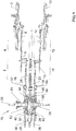
En référence à la
- une source d'énergie mécanique 1, tel qu'un barillet,
- un premier organe réglant 2 et un
premier échappement 4, comprenant une première roue d'échappement 5 et une première ancre 6, reliés par unpremier rouage 8 à ladite source d'énergie 1, lepremier rouage 8, lepremier échappement 4 et le premier organe réglant 2 définissant un premier ensemble, - un deuxième organe réglant 10 et un
deuxième échappement 12 comprenant une deuxième roue d'échappement 13 et unedeuxième ancre 14, reliés par undeuxième rouage 16 à ladite source d'énergie 1, ledeuxième rouage 16, ledeuxième échappement 12 et le deuxième organe réglant 10 définissant un deuxième ensemble, - un engrenage différentiel 18 agencé pour assurer une liaison cinématique entre le premier ensemble et la source d'énergie 1 d'une part et entre le deuxième ensemble et la source d'énergie 1 d'autre part.
- a source of
mechanical energy 1, such as a cylinder, - a
first regulating member 2 and afirst escapement 4, comprising a first escape wheel 5 and a first anchor 6, connected by afirst wheel 8 to saidenergy source 1, thefirst wheel 8, thefirst escapement 4 and the first regulatingmember 2 defining a first set, - a second regulating
member 10 and asecond escapement 12 comprising asecond escape wheel 13 and asecond anchor 14, connected by asecond wheel 16 to saidenergy source 1, thesecond wheel 16, thesecond exhaust 12 and the second regulatingmember 10 defining a second set, - a
differential gear 18 arranged to ensure a kinematic connection between the first set and theenergy source 1 on the one hand and between the second set and theenergy source 1 on the other hand.
Dans la variante représentée ici, les organes réglants 2 et 10 sont des balanciers simples, mais il est bien évident qu'ils peuvent être également des tourbillons ou des carrousels. De même, les premier et deuxième échappements représentés sont à ancre suisse mais ils pourraient être d'un autre type, tel que des échappements à détente ou d'autres types d'échappement connus.In the variant shown here, the regulating
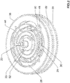
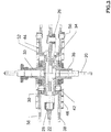
En référence plus particulièrement aux
L'engrenage différentiel 18 comprend une roue d'entrée 22 montée pivotante autour de l'arbre 20 et présentant une denture extérieure engrenant avec un renvoi 24 engrenant lui-même avec la source d'énergie 1. Il est bien évident que le mécanisme peut comprendre d'autres mobiles que le renvoi 24 entre l'engrenage différentiel 18 et la source d'énergie 1.The
La roue d'entrée 22 est solidaire d'un porte-satellite 26 qui comporte des arbres 28 perpendiculaires à l'arbre 20 et sur chacun desquels est monté pivotant un pignon-satellite 30. Dans la variante représentée, les pignons-satellites 30 sont à denture conique.The
L'engrenage différentiel 18 comprend également une première roue de transmission 32 et une deuxième roue de transmission 34, respectivement montées pivotantes autour de l'arbre 20 au moyen d'un canon 33 et 35 respectivement. Chacune des première et deuxième roues de transmission 32, 34 présente une denture conique disposée de part et d'autre des pignons-satellites 30. Les dentures coniques des première et deuxième roues de transmission 32, 34 sont choisies de sorte qu'elles engrènent avec les dentures coniques des pignons-satellites 30.The
Les première et deuxième roues de transmission 32, 34 représentées ici sont sous la forme de roue-cloche, mais il est bien évident que toute roue de transmission d'un différentiel plat peut convenir. De même la forme des dentures des pignons-satellites et des dentures des roues de transmission est adaptée à la construction du différentiel. Notamment, les dentures peuvent être droites.The first and
L'engrenage différentiel 18 comprend également une première roue de sortie 36 et une deuxième roue de sortie 38, respectivement montées libres en rotation autour de l'arbre 20, et disposées à l'extérieur des première et deuxième roues de transmission 32, 34 respectivement.The
La première roue de sortie 36 présente une denture extérieure engrenant avec le premier rouage 8 et la deuxième roue de sortie 38 présente une denture extérieure engrenant avec le deuxième rouage 16.The
Une première goupille 40 est chassée dans la première roue de transmission 32 et insérée avec du jeu dans un trou prévu dans la première roue de sortie 36. De même, une deuxième goupille 42 est chassée dans la deuxième roue de transmission 34 et insérée avec du jeu dans un trou prévu dans la deuxième roue de sortie 38. Le rôle de ces goupilles 40, 42 sera décrit ci-après.A
Conformément à l'invention, le mouvement comporte en outre :
- un premier organe ressort ou élastique 44 prévu entre l'engrenage différentiel 18 et le
premier échappement 4 et armé pour exercer un couple sur la première roue desortie 36, - un deuxième organe ressort ou élastique 46 prévu entre l'engrenage différentiel 18 et le deuxième échappement 12 et armé pour exercer un couple sur la deuxième roue de
sortie 38.
- a first spring or
elastic member 44 provided between thedifferential gear 18 and thefirst escapement 4 and cocked to exert a torque on thefirst output wheel 36, - a second spring or
elastic member 46 provided between thedifferential gear 18 and thesecond escapement 12 and cocked to exert a torque on thesecond output wheel 38.
Plus précisément, le premier organe ressort 44 est placé à l'extérieur de la première roue de sortie 36, à l'opposé de la première roue de transmission 32, concentriquement à l'arbre 20. Il présente une première extrémité 48 solidaire de la première roue de sortie 36 au moyen d'une goupille 50 et une seconde extrémité 52 solidaire du canon 33 de la première roue de transmission 32.More specifically, the
De même, le deuxième organe ressort 46 est placé à l'extérieur de la deuxième roue de sortie 38, à l'opposé de la deuxième roue de transmission 34, concentriquement à l'arbre 20. Il présente une première extrémité 54 solidaire de la deuxième roue de sortie 38 au moyen d'une goupille 56 et une seconde extrémité 58 solidaire du canon 35 de la deuxième roue de transmission 34.Similarly, the
Un pré-armage des premier et deuxième organes ressorts peut être prévu lors de construction du mouvement.Pre-arming of the first and second spring members may be provided during movement construction.
Dans une autre variante de construction non représentée, le premier organe ressort 44 peut être placé à l'intérieur de la première roue de sortie 36, du même côté que la première roue de transmission 32, et le deuxième organe ressort 46 peut être placé à l'intérieur de la deuxième roue de sortie 38, du même côté que la deuxième roue de transmission 34.In another variant of construction not shown, the
Dans la variante représentée, les organes ressorts 44 et 46 sont des ressorts spiraux.In the variant shown, the
Il est bien évident que d'autres variantes de réalisation peuvent être prévues, telles que par exemple remplacer le spiral et la roue de sortie associée par une roue intégrant un élément élastique. Les organes ressorts ou éléments élastiques peuvent être de tout type de forme (boudin, spiral, lame-ressort, etc.), et de toute matière, la forme et la matière étant choisies pour que lesdits organes ressorts ou éléments élastiques permettent d'emmagasiner et de restituer de l'énergie.It is obvious that other embodiments may be provided, such as for example replace the spiral and the output wheel associated with a wheel incorporating an elastic member. The spring members or elastic members may be of any type of shape (coil, spiral, leaf spring, etc.), and any material, the shape and the material being chosen so that said springs or elastic members can store and to restore energy.
Le fonctionnement du mouvement selon l'invention est le suivant :The operation of the movement according to the invention is as follows:
Lors du fonctionnement, la force motrice arrivant de la source d'énergie 1 entre dans l'engrenage différentiel 18 par le renvoi 24, la roue d'entrée 22 et le porte-satellite 26 qui porte les pignons-satellites 30.During operation, the driving force arriving from the
Lorsque les première et deuxième ancres 6 et 14 libèrent les roues d'échappement 5 et 13 respectivement, les roues de sortie associées 36 et 38 respectivement transmettent un couple à leur rouage associé 8 et 16 respectivement. Comme les organes ressorts 44 et 46 sont pré-armés sur leur roue de sortie associée 36 et 38 respectivement, ces dernières vont tourner dès qu'elles en auront la possibilité. Les roues de sortie 36 et 38 vont se mettre en mouvement avant les roues de transmission 32 et 34. En effet, les roues de sortie 36 et 38 sont plus proches des échappements 4 et 12 que les roues de transmission 32 et 34. Ainsi, le chemin de force à parcourir étant moins important pour parvenir aux roues de sortie 36 et 38, ces dernières ont un temps de réaction plus rapide que les roues de transmission 32 et 34.When the first and
Ce mécanisme permet de transmettre aux roues de sortie 36 et 38 des forces qui proviennent exclusivement de leurs organes ressorts respectifs 44 et 46. Cette transmission se déroule également lorsque les impulsions des organes réglants 2 et 10 sont simultanées.This mechanism makes it possible to transmit to the
Ainsi, chaque organe réglant 2 et 10 reçoit instantanément l'énergie qui lui est nécessaire sans perturber l'autre. De ce fait, tous les effets indésirables rencontrés avec les engrenages différentiels connus de l'art antérieur sont supprimés, y compris lorsque les impulsions sont simultanées.Thus, each regulating
Afin de permettre le réarmage de leur organe ressort associé 44, 46, les première et deuxième roues de transmission 32, 34, entrainées par la source d'énergie 1, vont rattraper leurs décalages respectifs par rapport aux roues de sortie associées 36, 38. Ainsi, le couple initial des organes ressorts 44 et 46 sera rétabli. De plus, les goupilles 40, 42 servent de butée aux roues de transmission 32 et 34 dans les roues de sortie 36, 38 lorsqu'elles rattrapent leurs décalages, afin de toujours réarmer l'organe ressort associé 44, 46 avec un même couple.In order to allow the rearming of their associated
Le cycle peut alors reprendre.The cycle can then resume.
Il est bien évident que la présente invention n'est pas limitée à l'exemple de réalisation décrit. Notamment, le mouvement d'horlogerie peut comprendre plusieurs engrenages différentiels qui se suivent, placés entre un engrenage différentiel principal, situé le plus proche de la source d'énergie, et l'échappement du premier et/ou du deuxième ensemble. Dans ce cas, le premier organe ressort prévu entre l'engrenage différentiel principal et le premier échappement peut être plus spécifiquement disposé entre la sortie de l'engrenage différentiel principal et l'entrée de l'élément coopérant suivant, à savoir un deuxième engrenage différentiel. De même, le deuxième organe ressort prévu entre l'engrenage différentiel principal et le deuxième échappement peut être plus spécifiquement disposé entre la sortie de l'engrenage différentiel principal et l'entrée de l'élément coopérant suivant, à savoir un troisième engrenage différentiel.It is obvious that the present invention is not limited to the embodiment described. In particular, the watch movement may comprise several successive differential gears, placed between a main differential gear, located closest to the energy source, and the exhaust of the first and / or second set. In this case, the first spring member provided between the main differential gear and the first escapement may be more specifically disposed between the output of the main differential gear and the input of the next cooperating element, namely a second differential gear. . Similarly, the second spring member provided between the main differential gear and the second escapement may be more specifically disposed between the output of the main differential gear and the input of the next cooperating element, namely a third differential gear.
Claims (9)
- Timepiece movement including:- a mechanical energy source (1),- a first regulating organ (2) and a first escapement (4) linked by a first gear train (8) to said energy source (1), the first gear train (8), the first escapement (4) and the first regulating organ (2) defining a first ensemble,- a second regulating organ (10) and a second escapement (12) linked by a second gear train (16) to said energy source (1), the second gear train (16), the second escapement (12) and the second regulating organ (10) defining a second ensemble,- at least one differential gear (18) arranged to provide a kinematic link firstly between the first ensemble and the energy source (1) and secondly between the second ensemble and the energy source (1), characterized in that said movement also comprises:- a first spring organ (44) provided between the differential gear (18) and the first escapement (4) and arranged to exert torque on a first output of the differential gear (18),- first means for re-charging said first spring organ (44),- a second spring organ (46) provided between the differential gear (18) and the second escapement (12) and arranged to apply torque to a second output of the differential gear (18), and- second means for re-charging said second spring organ (10).
- Movement according to claim 1, characterized in that the differential gear (18) comprises a first transmission wheel (32) and a first output wheel (36) mounted freely in rotation and linked kinematically to the first ensemble, and in that said first spring organ (44) has a first extremity (48) linked to said first output wheel (36) and a second extremity (52) linked to said first transmission wheel (32).
- Movement according to one of claims 1 or 2, characterized in that the differential gear (18) comprises a second transmission wheel (34) and a second output wheel (38) mounted freely in rotation and linked kinematically to the second ensemble, and in that said second spring organ (46) has a first extremity (54) linked to said second output wheel (38) and a second extremity (58) linked to said second transmission wheel (34).
- Movement according to claim 2, characterized in that the first means for re-charging the first spring organ (44) comprise first driving means (40) for the first output wheel (36) that are rigidly connected to the first transmission wheel (32).
- Movement according to claim 3, characterized in that the second means for re-loading the second spring organ (46) comprise second driving means (42) for the second output wheel (38) that are rigidly connected to the second transmission wheel (34).
- Movement according to any one of the preceding claims, characterized in that the differential gear (18) comprises an input wheel (22) linked kinematically to the energy source (1).
- Movement according to claims 2, 3 and 6, characterized in that the input wheel (22) carries at least one satellite pinion (30) arranged to cooperate with each of the first and second transmission wheels (32, 34).
- Movement according to any one of the preceding claims, characterized in that each of the first and second spring organs (44, 46) is a spiral spring.
- Timepiece comprising a movement according to any one of claims 1 to 8.
Applications Claiming Priority (2)
| Application Number | Priority Date | Filing Date | Title |
|---|---|---|---|
| CH01697/13A CH708658A1 (en) | 2013-10-03 | 2013-10-03 | Clockwork movement comprising a differential gear between regulating members. |
| PCT/EP2014/069053 WO2015049090A1 (en) | 2013-10-03 | 2014-09-08 | Clockwork movement and timepiece including such a movement |
Publications (2)
| Publication Number | Publication Date |
|---|---|
| EP3052993A1 EP3052993A1 (en) | 2016-08-10 |
| EP3052993B1 true EP3052993B1 (en) | 2017-07-05 |
Family
ID=49322110
Family Applications (1)
| Application Number | Title | Priority Date | Filing Date |
|---|---|---|---|
| EP14765905.6A Active EP3052993B1 (en) | 2013-10-03 | 2014-09-08 | Clockwork movement and timepiece including such a movement |
Country Status (5)
| Country | Link |
|---|---|
| US (1) | US9588492B2 (en) |
| EP (1) | EP3052993B1 (en) |
| CN (1) | CN105765465B (en) |
| CH (1) | CH708658A1 (en) |
| WO (1) | WO2015049090A1 (en) |
Families Citing this family (11)
| Publication number | Priority date | Publication date | Assignee | Title |
|---|---|---|---|---|
| CH709394A1 (en) * | 2014-03-21 | 2015-09-30 | Gfpi S A | clockwork. |
| EP3191897B1 (en) * | 2014-09-09 | 2019-01-02 | ETA SA Manufacture Horlogère Suisse | Mechanism for synchronization of two timepiece oscillators with a wheel train |
| CH712100A2 (en) | 2016-02-08 | 2017-08-15 | Hepta Swiss Sa | Watch movement with two pendulums. |
| EP3339974A1 (en) * | 2016-12-22 | 2018-06-27 | Montres Breguet S.A. | Mechanism for clearance compensation between a first kinematic chain and a second kinematic chain of a clockwork mechanism |
| EP3382468B1 (en) * | 2017-03-30 | 2020-01-15 | The Swatch Group Research and Development Ltd | Movement with extension of running reserve |
| JP6847758B2 (en) * | 2017-05-09 | 2021-03-24 | セイコーインスツル株式会社 | Movement and watches |
| JP6847757B2 (en) * | 2017-05-09 | 2021-03-24 | セイコーインスツル株式会社 | Movement and watches |
| EP3599515B1 (en) * | 2018-07-24 | 2022-07-06 | Harry Winston SA | Timepiece driving mechanism |
| EP3599516B1 (en) * | 2018-07-24 | 2024-04-03 | Harry Winston SA | Timepiece retrograde tourbillon or karussel |
| EP3599517B1 (en) * | 2018-07-24 | 2021-03-10 | Harry Winston SA | Timepiece retrograde tourbillon or karussel |
| FR3107603B1 (en) * | 2020-02-26 | 2022-01-21 | Vianney Halter | “Tourbillon with two oscillators in a cage” |
Family Cites Families (7)
| Publication number | Priority date | Publication date | Assignee | Title |
|---|---|---|---|---|
| EP1615085B1 (en) * | 2004-07-08 | 2008-08-27 | Audemars Piguet (Renaud et Papi) SA | Correction mechanism for the seating of a regulator device for balance-spring |
| CH698622B1 (en) * | 2004-12-21 | 2009-09-15 | Gfpi S A | Movement for mechanical timepiece, has differential gear assuring kinematic connection between finishing gear-train and escapements i.e. tourbillons, of time base, where upper and lower wheels respectively interlock escapements |
| JP4846781B2 (en) * | 2005-03-23 | 2011-12-28 | ベエヌベ コンセプ エセア | Watch movement |
| ATE470890T1 (en) * | 2005-03-30 | 2010-06-15 | Montres Breguet Sa | WATCH WITH AT LEAST TWO REGULATION SYSTEMS |
| EP2221676B1 (en) * | 2009-02-24 | 2011-07-20 | Montres Breguet SA | Timepiece including a chronograph and a watch |
| CH704063B1 (en) * | 2010-11-09 | 2013-07-31 | Complitime Sa | Timepiece |
| CH705494A2 (en) * | 2011-09-15 | 2013-03-15 | Swatch Group Res & Dev Ltd | Clock element for keyless watch, has wheel connected to another wheel by set of coupling units or rubber band for synchronizing oscillator or another oscillator using energy source |
-
2013
- 2013-10-03 CH CH01697/13A patent/CH708658A1/en not_active Application Discontinuation
-
2014
- 2014-09-08 CN CN201480053091.3A patent/CN105765465B/en active Active
- 2014-09-08 EP EP14765905.6A patent/EP3052993B1/en active Active
- 2014-09-08 WO PCT/EP2014/069053 patent/WO2015049090A1/en active Application Filing
- 2014-09-08 US US15/024,182 patent/US9588492B2/en active Active
Non-Patent Citations (1)
| Title |
|---|
| None * |
Also Published As
| Publication number | Publication date |
|---|---|
| CH708658A1 (en) | 2015-04-15 |
| US9588492B2 (en) | 2017-03-07 |
| EP3052993A1 (en) | 2016-08-10 |
| CN105765465B (en) | 2017-09-15 |
| WO2015049090A1 (en) | 2015-04-09 |
| CN105765465A (en) | 2016-07-13 |
| US20160231708A1 (en) | 2016-08-11 |
Similar Documents
| Publication | Publication Date | Title |
|---|---|---|
| EP3052993B1 (en) | Clockwork movement and timepiece including such a movement | |
| EP2214065B1 (en) | Timepiece movement equipped with a vibrating alarm | |
| EP2166419B1 (en) | Clockwork comprising a constant-force device | |
| EP2548084B1 (en) | Movement for a timepiece with equalizing winding mechanism | |
| EP3021175B1 (en) | Split-seconds device with epicycloidal train for a timepiece | |
| EP3764168B1 (en) | Timepiece display mechanism with elastic hand | |
| EP2801868B1 (en) | Escapement wheel | |
| EP3120198B1 (en) | Clockwork | |
| EP2776894A1 (en) | Mechanism for driving an indicator | |
| EP3705949A1 (en) | Torque limiter mechanism for a timepiece | |
| EP2622416A1 (en) | Timepiece | |
| EP3904964B1 (en) | Device for displaying a time or time-derived indication and device for indexing | |
| EP3306416B1 (en) | Mechanical clock movement with power-reserve detection | |
| EP2112564B1 (en) | Clutch device | |
| EP3376309B1 (en) | Winding mechanism of a timepiece | |
| CH710521B1 (en) | Device for generating electricity on demand for timepieces. | |
| EP3904962B1 (en) | Device for indexing and device for displaying a time or time-derived indication | |
| CH709755A2 (en) | clockwork mechanism with a tuning fork resonator. | |
| CH715905A2 (en) | Clockwork torque limiter mechanism. | |
| EP4254079A1 (en) | Mechanism for displaying the phases of the moon for a timepiece | |
| CH715152B1 (en) | Large date type date display mechanism. | |
| CH709204A2 (en) | A control device for watch mechanism and watch mechanism comprising such a device. | |
| EP4060428A1 (en) | Driving mechanism for timepiece movement, in particular a chronograph mechanism comprising such a driving mechanism | |
| CH719559A2 (en) | Timepiece moon phase display mechanism. | |
| CH715417A2 (en) | Watch movement comprising a plurality of barrels. |
Legal Events
| Date | Code | Title | Description |
|---|---|---|---|
| PUAI | Public reference made under article 153(3) epc to a published international application that has entered the european phase |
Free format text: ORIGINAL CODE: 0009012 |
|
| 17P | Request for examination filed |
Effective date: 20160405 |
|
| AK | Designated contracting states |
Kind code of ref document: A1 Designated state(s): AL AT BE BG CH CY CZ DE DK EE ES FI FR GB GR HR HU IE IS IT LI LT LU LV MC MK MT NL NO PL PT RO RS SE SI SK SM TR |
|
| AX | Request for extension of the european patent |
Extension state: BA ME |
|
| DAX | Request for extension of the european patent (deleted) | ||
| REG | Reference to a national code |
Ref country code: DE Ref legal event code: R079 Ref document number: 602014011546 Country of ref document: DE Free format text: PREVIOUS MAIN CLASS: G04B0015000000 Ipc: G04B0001160000 |
|
| GRAP | Despatch of communication of intention to grant a patent |
Free format text: ORIGINAL CODE: EPIDOSNIGR1 |
|
| STAA | Information on the status of an ep patent application or granted ep patent |
Free format text: STATUS: GRANT OF PATENT IS INTENDED |
|
| RIC1 | Information provided on ipc code assigned before grant |
Ipc: G04B 13/02 20060101ALI20170203BHEP Ipc: G04B 17/26 20060101ALI20170203BHEP Ipc: G04B 1/22 20060101ALI20170203BHEP Ipc: G04B 15/14 20060101ALI20170203BHEP Ipc: G04B 1/16 20060101AFI20170203BHEP Ipc: G04B 17/32 20060101ALI20170203BHEP Ipc: G04B 13/00 20060101ALI20170203BHEP Ipc: G04B 15/00 20060101ALI20170203BHEP |
|
| INTG | Intention to grant announced |
Effective date: 20170308 |
|
| GRAS | Grant fee paid |
Free format text: ORIGINAL CODE: EPIDOSNIGR3 |
|
| GRAA | (expected) grant |
Free format text: ORIGINAL CODE: 0009210 |
|
| STAA | Information on the status of an ep patent application or granted ep patent |
Free format text: STATUS: THE PATENT HAS BEEN GRANTED |
|
| AK | Designated contracting states |
Kind code of ref document: B1 Designated state(s): AL AT BE BG CH CY CZ DE DK EE ES FI FR GB GR HR HU IE IS IT LI LT LU LV MC MK MT NL NO PL PT RO RS SE SI SK SM TR |
|
| REG | Reference to a national code |
Ref country code: GB Ref legal event code: FG4D Free format text: NOT ENGLISH |
|
| REG | Reference to a national code |
Ref country code: CH Ref legal event code: EP |
|
| REG | Reference to a national code |
Ref country code: AT Ref legal event code: REF Ref document number: 907003 Country of ref document: AT Kind code of ref document: T Effective date: 20170715 |
|
| REG | Reference to a national code |
Ref country code: IE Ref legal event code: FG4D Free format text: LANGUAGE OF EP DOCUMENT: FRENCH |
|
| REG | Reference to a national code |
Ref country code: DE Ref legal event code: R096 Ref document number: 602014011546 Country of ref document: DE |
|
| REG | Reference to a national code |
Ref country code: CH Ref legal event code: NV Representative=s name: E-PATENT S.A., CH |
|
| REG | Reference to a national code |
Ref country code: FR Ref legal event code: PLFP Year of fee payment: 4 |
|
| REG | Reference to a national code |
Ref country code: NL Ref legal event code: MP Effective date: 20170705 |
|
| REG | Reference to a national code |
Ref country code: AT Ref legal event code: MK05 Ref document number: 907003 Country of ref document: AT Kind code of ref document: T Effective date: 20170705 |
|
| REG | Reference to a national code |
Ref country code: LT Ref legal event code: MG4D |
|
| PG25 | Lapsed in a contracting state [announced via postgrant information from national office to epo] |
Ref country code: LT Free format text: LAPSE BECAUSE OF FAILURE TO SUBMIT A TRANSLATION OF THE DESCRIPTION OR TO PAY THE FEE WITHIN THE PRESCRIBED TIME-LIMIT Effective date: 20170705 Ref country code: SE Free format text: LAPSE BECAUSE OF FAILURE TO SUBMIT A TRANSLATION OF THE DESCRIPTION OR TO PAY THE FEE WITHIN THE PRESCRIBED TIME-LIMIT Effective date: 20170705 Ref country code: HR Free format text: LAPSE BECAUSE OF FAILURE TO SUBMIT A TRANSLATION OF THE DESCRIPTION OR TO PAY THE FEE WITHIN THE PRESCRIBED TIME-LIMIT Effective date: 20170705 Ref country code: NO Free format text: LAPSE BECAUSE OF FAILURE TO SUBMIT A TRANSLATION OF THE DESCRIPTION OR TO PAY THE FEE WITHIN THE PRESCRIBED TIME-LIMIT Effective date: 20171005 Ref country code: AT Free format text: LAPSE BECAUSE OF FAILURE TO SUBMIT A TRANSLATION OF THE DESCRIPTION OR TO PAY THE FEE WITHIN THE PRESCRIBED TIME-LIMIT Effective date: 20170705 Ref country code: NL Free format text: LAPSE BECAUSE OF FAILURE TO SUBMIT A TRANSLATION OF THE DESCRIPTION OR TO PAY THE FEE WITHIN THE PRESCRIBED TIME-LIMIT Effective date: 20170705 Ref country code: FI Free format text: LAPSE BECAUSE OF FAILURE TO SUBMIT A TRANSLATION OF THE DESCRIPTION OR TO PAY THE FEE WITHIN THE PRESCRIBED TIME-LIMIT Effective date: 20170705 |
|
| PG25 | Lapsed in a contracting state [announced via postgrant information from national office to epo] |
Ref country code: PL Free format text: LAPSE BECAUSE OF FAILURE TO SUBMIT A TRANSLATION OF THE DESCRIPTION OR TO PAY THE FEE WITHIN THE PRESCRIBED TIME-LIMIT Effective date: 20170705 Ref country code: IS Free format text: LAPSE BECAUSE OF FAILURE TO SUBMIT A TRANSLATION OF THE DESCRIPTION OR TO PAY THE FEE WITHIN THE PRESCRIBED TIME-LIMIT Effective date: 20171105 Ref country code: ES Free format text: LAPSE BECAUSE OF FAILURE TO SUBMIT A TRANSLATION OF THE DESCRIPTION OR TO PAY THE FEE WITHIN THE PRESCRIBED TIME-LIMIT Effective date: 20170705 Ref country code: BG Free format text: LAPSE BECAUSE OF FAILURE TO SUBMIT A TRANSLATION OF THE DESCRIPTION OR TO PAY THE FEE WITHIN THE PRESCRIBED TIME-LIMIT Effective date: 20171005 Ref country code: LV Free format text: LAPSE BECAUSE OF FAILURE TO SUBMIT A TRANSLATION OF THE DESCRIPTION OR TO PAY THE FEE WITHIN THE PRESCRIBED TIME-LIMIT Effective date: 20170705 Ref country code: RS Free format text: LAPSE BECAUSE OF FAILURE TO SUBMIT A TRANSLATION OF THE DESCRIPTION OR TO PAY THE FEE WITHIN THE PRESCRIBED TIME-LIMIT Effective date: 20170705 Ref country code: GR Free format text: LAPSE BECAUSE OF FAILURE TO SUBMIT A TRANSLATION OF THE DESCRIPTION OR TO PAY THE FEE WITHIN THE PRESCRIBED TIME-LIMIT Effective date: 20171006 |
|
| REG | Reference to a national code |
Ref country code: DE Ref legal event code: R097 Ref document number: 602014011546 Country of ref document: DE |
|
| PG25 | Lapsed in a contracting state [announced via postgrant information from national office to epo] |
Ref country code: RO Free format text: LAPSE BECAUSE OF FAILURE TO SUBMIT A TRANSLATION OF THE DESCRIPTION OR TO PAY THE FEE WITHIN THE PRESCRIBED TIME-LIMIT Effective date: 20170705 Ref country code: CZ Free format text: LAPSE BECAUSE OF FAILURE TO SUBMIT A TRANSLATION OF THE DESCRIPTION OR TO PAY THE FEE WITHIN THE PRESCRIBED TIME-LIMIT Effective date: 20170705 Ref country code: DK Free format text: LAPSE BECAUSE OF FAILURE TO SUBMIT A TRANSLATION OF THE DESCRIPTION OR TO PAY THE FEE WITHIN THE PRESCRIBED TIME-LIMIT Effective date: 20170705 |
|
| PLBE | No opposition filed within time limit |
Free format text: ORIGINAL CODE: 0009261 |
|
| STAA | Information on the status of an ep patent application or granted ep patent |
Free format text: STATUS: NO OPPOSITION FILED WITHIN TIME LIMIT |
|
| PG25 | Lapsed in a contracting state [announced via postgrant information from national office to epo] |
Ref country code: IT Free format text: LAPSE BECAUSE OF FAILURE TO SUBMIT A TRANSLATION OF THE DESCRIPTION OR TO PAY THE FEE WITHIN THE PRESCRIBED TIME-LIMIT Effective date: 20170705 Ref country code: EE Free format text: LAPSE BECAUSE OF FAILURE TO SUBMIT A TRANSLATION OF THE DESCRIPTION OR TO PAY THE FEE WITHIN THE PRESCRIBED TIME-LIMIT Effective date: 20170705 Ref country code: MC Free format text: LAPSE BECAUSE OF FAILURE TO SUBMIT A TRANSLATION OF THE DESCRIPTION OR TO PAY THE FEE WITHIN THE PRESCRIBED TIME-LIMIT Effective date: 20170705 Ref country code: SK Free format text: LAPSE BECAUSE OF FAILURE TO SUBMIT A TRANSLATION OF THE DESCRIPTION OR TO PAY THE FEE WITHIN THE PRESCRIBED TIME-LIMIT Effective date: 20170705 Ref country code: SM Free format text: LAPSE BECAUSE OF FAILURE TO SUBMIT A TRANSLATION OF THE DESCRIPTION OR TO PAY THE FEE WITHIN THE PRESCRIBED TIME-LIMIT Effective date: 20170705 |
|
| 26N | No opposition filed |
Effective date: 20180406 |
|
| REG | Reference to a national code |
Ref country code: IE Ref legal event code: MM4A |
|
| REG | Reference to a national code |
Ref country code: BE Ref legal event code: MM Effective date: 20170930 |
|
| PG25 | Lapsed in a contracting state [announced via postgrant information from national office to epo] |
Ref country code: LU Free format text: LAPSE BECAUSE OF NON-PAYMENT OF DUE FEES Effective date: 20170908 |
|
| PG25 | Lapsed in a contracting state [announced via postgrant information from national office to epo] |
Ref country code: IE Free format text: LAPSE BECAUSE OF NON-PAYMENT OF DUE FEES Effective date: 20170908 |
|
| PG25 | Lapsed in a contracting state [announced via postgrant information from national office to epo] |
Ref country code: BE Free format text: LAPSE BECAUSE OF NON-PAYMENT OF DUE FEES Effective date: 20170930 Ref country code: SI Free format text: LAPSE BECAUSE OF FAILURE TO SUBMIT A TRANSLATION OF THE DESCRIPTION OR TO PAY THE FEE WITHIN THE PRESCRIBED TIME-LIMIT Effective date: 20170705 |
|
| REG | Reference to a national code |
Ref country code: FR Ref legal event code: PLFP Year of fee payment: 5 |
|
| PG25 | Lapsed in a contracting state [announced via postgrant information from national office to epo] |
Ref country code: MT Free format text: LAPSE BECAUSE OF FAILURE TO SUBMIT A TRANSLATION OF THE DESCRIPTION OR TO PAY THE FEE WITHIN THE PRESCRIBED TIME-LIMIT Effective date: 20170705 |
|
| PG25 | Lapsed in a contracting state [announced via postgrant information from national office to epo] |
Ref country code: HU Free format text: LAPSE BECAUSE OF FAILURE TO SUBMIT A TRANSLATION OF THE DESCRIPTION OR TO PAY THE FEE WITHIN THE PRESCRIBED TIME-LIMIT; INVALID AB INITIO Effective date: 20140908 |
|
| PG25 | Lapsed in a contracting state [announced via postgrant information from national office to epo] |
Ref country code: CY Free format text: LAPSE BECAUSE OF FAILURE TO SUBMIT A TRANSLATION OF THE DESCRIPTION OR TO PAY THE FEE WITHIN THE PRESCRIBED TIME-LIMIT Effective date: 20170705 |
|
| PG25 | Lapsed in a contracting state [announced via postgrant information from national office to epo] |
Ref country code: MK Free format text: LAPSE BECAUSE OF FAILURE TO SUBMIT A TRANSLATION OF THE DESCRIPTION OR TO PAY THE FEE WITHIN THE PRESCRIBED TIME-LIMIT Effective date: 20170705 |
|
| PG25 | Lapsed in a contracting state [announced via postgrant information from national office to epo] |
Ref country code: TR Free format text: LAPSE BECAUSE OF FAILURE TO SUBMIT A TRANSLATION OF THE DESCRIPTION OR TO PAY THE FEE WITHIN THE PRESCRIBED TIME-LIMIT Effective date: 20170705 |
|
| PG25 | Lapsed in a contracting state [announced via postgrant information from national office to epo] |
Ref country code: PT Free format text: LAPSE BECAUSE OF FAILURE TO SUBMIT A TRANSLATION OF THE DESCRIPTION OR TO PAY THE FEE WITHIN THE PRESCRIBED TIME-LIMIT Effective date: 20170705 |
|
| PG25 | Lapsed in a contracting state [announced via postgrant information from national office to epo] |
Ref country code: AL Free format text: LAPSE BECAUSE OF FAILURE TO SUBMIT A TRANSLATION OF THE DESCRIPTION OR TO PAY THE FEE WITHIN THE PRESCRIBED TIME-LIMIT Effective date: 20170705 |
|
| PGFP | Annual fee paid to national office [announced via postgrant information from national office to epo] |
Ref country code: GB Payment date: 20230927 Year of fee payment: 10 |
|
| PGFP | Annual fee paid to national office [announced via postgrant information from national office to epo] |
Ref country code: FR Payment date: 20230925 Year of fee payment: 10 Ref country code: DE Payment date: 20230927 Year of fee payment: 10 |
|
| PGFP | Annual fee paid to national office [announced via postgrant information from national office to epo] |
Ref country code: CH Payment date: 20231003 Year of fee payment: 10 |