EP3052852B1 - Beleuchtungsvorrichtung für fahrzeuge - Google Patents
Beleuchtungsvorrichtung für fahrzeuge Download PDFInfo
- Publication number
- EP3052852B1 EP3052852B1 EP14777621.5A EP14777621A EP3052852B1 EP 3052852 B1 EP3052852 B1 EP 3052852B1 EP 14777621 A EP14777621 A EP 14777621A EP 3052852 B1 EP3052852 B1 EP 3052852B1
- Authority
- EP
- European Patent Office
- Prior art keywords
- light guide
- light
- low profile
- lighting device
- flat side
- Prior art date
- Legal status (The legal status is an assumption and is not a legal conclusion. Google has not performed a legal analysis and makes no representation as to the accuracy of the status listed.)
- Active
Links
- 230000003287 optical effect Effects 0.000 claims description 46
- 239000002105 nanoparticle Substances 0.000 claims description 16
- 230000005855 radiation Effects 0.000 claims description 10
- 239000000463 material Substances 0.000 claims description 7
- 239000002245 particle Substances 0.000 claims description 6
- 238000001746 injection moulding Methods 0.000 claims description 4
- 238000007639 printing Methods 0.000 claims description 4
- 230000008878 coupling Effects 0.000 claims description 3
- 238000010168 coupling process Methods 0.000 claims description 3
- 238000005859 coupling reaction Methods 0.000 claims description 3
- 230000003628 erosive effect Effects 0.000 claims description 3
- 238000005530 etching Methods 0.000 claims description 3
- 238000010422 painting Methods 0.000 claims description 3
- 230000011514 reflex Effects 0.000 claims 12
- 238000009792 diffusion process Methods 0.000 claims 10
- 239000006185 dispersion Substances 0.000 claims 1
- 239000013307 optical fiber Substances 0.000 description 6
- 208000003028 Stuttering Diseases 0.000 description 4
- 239000004020 conductor Substances 0.000 description 3
- 238000009826 distribution Methods 0.000 description 3
- 230000008901 benefit Effects 0.000 description 2
- 239000013078 crystal Substances 0.000 description 2
- 238000005286 illumination Methods 0.000 description 2
- 238000000149 argon plasma sintering Methods 0.000 description 1
- 238000010276 construction Methods 0.000 description 1
- 230000009977 dual effect Effects 0.000 description 1
- 230000000694 effects Effects 0.000 description 1
- 238000002347 injection Methods 0.000 description 1
- 239000007924 injection Substances 0.000 description 1
- 238000003754 machining Methods 0.000 description 1
- 238000004519 manufacturing process Methods 0.000 description 1
- 239000004065 semiconductor Substances 0.000 description 1
- 239000013585 weight reducing agent Substances 0.000 description 1
Images


Classifications
-
- F—MECHANICAL ENGINEERING; LIGHTING; HEATING; WEAPONS; BLASTING
- F21—LIGHTING
- F21S—NON-PORTABLE LIGHTING DEVICES; SYSTEMS THEREOF; VEHICLE LIGHTING DEVICES SPECIALLY ADAPTED FOR VEHICLE EXTERIORS
- F21S43/00—Signalling devices specially adapted for vehicle exteriors, e.g. brake lamps, direction indicator lights or reversing lights
- F21S43/20—Signalling devices specially adapted for vehicle exteriors, e.g. brake lamps, direction indicator lights or reversing lights characterised by refractors, transparent cover plates, light guides or filters
- F21S43/235—Light guides
- F21S43/236—Light guides characterised by the shape of the light guide
- F21S43/239—Light guides characterised by the shape of the light guide plate-shaped
-
- B—PERFORMING OPERATIONS; TRANSPORTING
- B60—VEHICLES IN GENERAL
- B60Q—ARRANGEMENT OF SIGNALLING OR LIGHTING DEVICES, THE MOUNTING OR SUPPORTING THEREOF OR CIRCUITS THEREFOR, FOR VEHICLES IN GENERAL
- B60Q1/00—Arrangement of optical signalling or lighting devices, the mounting or supporting thereof or circuits therefor
- B60Q1/0029—Spatial arrangement
- B60Q1/0041—Spatial arrangement of several lamps in relation to each other
- B60Q1/0058—Stacked, i.e. one lamp located behind the other in the optical axis direction
-
- B—PERFORMING OPERATIONS; TRANSPORTING
- B60—VEHICLES IN GENERAL
- B60Q—ARRANGEMENT OF SIGNALLING OR LIGHTING DEVICES, THE MOUNTING OR SUPPORTING THEREOF OR CIRCUITS THEREFOR, FOR VEHICLES IN GENERAL
- B60Q1/00—Arrangement of optical signalling or lighting devices, the mounting or supporting thereof or circuits therefor
- B60Q1/26—Arrangement of optical signalling or lighting devices, the mounting or supporting thereof or circuits therefor the devices being primarily intended to indicate the vehicle, or parts thereof, or to give signals, to other traffic
- B60Q1/2607—Arrangement of optical signalling or lighting devices, the mounting or supporting thereof or circuits therefor the devices being primarily intended to indicate the vehicle, or parts thereof, or to give signals, to other traffic comprising at least two indicating lamps
-
- B—PERFORMING OPERATIONS; TRANSPORTING
- B60—VEHICLES IN GENERAL
- B60Q—ARRANGEMENT OF SIGNALLING OR LIGHTING DEVICES, THE MOUNTING OR SUPPORTING THEREOF OR CIRCUITS THEREFOR, FOR VEHICLES IN GENERAL
- B60Q1/00—Arrangement of optical signalling or lighting devices, the mounting or supporting thereof or circuits therefor
- B60Q1/26—Arrangement of optical signalling or lighting devices, the mounting or supporting thereof or circuits therefor the devices being primarily intended to indicate the vehicle, or parts thereof, or to give signals, to other traffic
- B60Q1/30—Arrangement of optical signalling or lighting devices, the mounting or supporting thereof or circuits therefor the devices being primarily intended to indicate the vehicle, or parts thereof, or to give signals, to other traffic for indicating rear of vehicle, e.g. by means of reflecting surfaces
- B60Q1/301—Arrangement of optical signalling or lighting devices, the mounting or supporting thereof or circuits therefor the devices being primarily intended to indicate the vehicle, or parts thereof, or to give signals, to other traffic for indicating rear of vehicle, e.g. by means of reflecting surfaces by means of surfaces, e.g. metal plate, reflecting the light of an external light source
- B60Q1/3015—Arrangement of optical signalling or lighting devices, the mounting or supporting thereof or circuits therefor the devices being primarily intended to indicate the vehicle, or parts thereof, or to give signals, to other traffic for indicating rear of vehicle, e.g. by means of reflecting surfaces by means of surfaces, e.g. metal plate, reflecting the light of an external light source combined with a lamp
-
- F—MECHANICAL ENGINEERING; LIGHTING; HEATING; WEAPONS; BLASTING
- F21—LIGHTING
- F21S—NON-PORTABLE LIGHTING DEVICES; SYSTEMS THEREOF; VEHICLE LIGHTING DEVICES SPECIALLY ADAPTED FOR VEHICLE EXTERIORS
- F21S43/00—Signalling devices specially adapted for vehicle exteriors, e.g. brake lamps, direction indicator lights or reversing lights
- F21S43/10—Signalling devices specially adapted for vehicle exteriors, e.g. brake lamps, direction indicator lights or reversing lights characterised by the light source
- F21S43/13—Signalling devices specially adapted for vehicle exteriors, e.g. brake lamps, direction indicator lights or reversing lights characterised by the light source characterised by the type of light source
- F21S43/14—Light emitting diodes [LED]
-
- F—MECHANICAL ENGINEERING; LIGHTING; HEATING; WEAPONS; BLASTING
- F21—LIGHTING
- F21S—NON-PORTABLE LIGHTING DEVICES; SYSTEMS THEREOF; VEHICLE LIGHTING DEVICES SPECIALLY ADAPTED FOR VEHICLE EXTERIORS
- F21S43/00—Signalling devices specially adapted for vehicle exteriors, e.g. brake lamps, direction indicator lights or reversing lights
- F21S43/20—Signalling devices specially adapted for vehicle exteriors, e.g. brake lamps, direction indicator lights or reversing lights characterised by refractors, transparent cover plates, light guides or filters
- F21S43/235—Light guides
- F21S43/242—Light guides characterised by the emission area
- F21S43/245—Light guides characterised by the emission area emitting light from one or more of its major surfaces
-
- F—MECHANICAL ENGINEERING; LIGHTING; HEATING; WEAPONS; BLASTING
- F21—LIGHTING
- F21S—NON-PORTABLE LIGHTING DEVICES; SYSTEMS THEREOF; VEHICLE LIGHTING DEVICES SPECIALLY ADAPTED FOR VEHICLE EXTERIORS
- F21S43/00—Signalling devices specially adapted for vehicle exteriors, e.g. brake lamps, direction indicator lights or reversing lights
- F21S43/20—Signalling devices specially adapted for vehicle exteriors, e.g. brake lamps, direction indicator lights or reversing lights characterised by refractors, transparent cover plates, light guides or filters
- F21S43/235—Light guides
- F21S43/249—Light guides with two or more light sources being coupled into the light guide
-
- F—MECHANICAL ENGINEERING; LIGHTING; HEATING; WEAPONS; BLASTING
- F21—LIGHTING
- F21S—NON-PORTABLE LIGHTING DEVICES; SYSTEMS THEREOF; VEHICLE LIGHTING DEVICES SPECIALLY ADAPTED FOR VEHICLE EXTERIORS
- F21S43/00—Signalling devices specially adapted for vehicle exteriors, e.g. brake lamps, direction indicator lights or reversing lights
- F21S43/30—Signalling devices specially adapted for vehicle exteriors, e.g. brake lamps, direction indicator lights or reversing lights characterised by reflectors
-
- B—PERFORMING OPERATIONS; TRANSPORTING
- B60—VEHICLES IN GENERAL
- B60Q—ARRANGEMENT OF SIGNALLING OR LIGHTING DEVICES, THE MOUNTING OR SUPPORTING THEREOF OR CIRCUITS THEREFOR, FOR VEHICLES IN GENERAL
- B60Q1/00—Arrangement of optical signalling or lighting devices, the mounting or supporting thereof or circuits therefor
- B60Q1/26—Arrangement of optical signalling or lighting devices, the mounting or supporting thereof or circuits therefor the devices being primarily intended to indicate the vehicle, or parts thereof, or to give signals, to other traffic
- B60Q1/30—Arrangement of optical signalling or lighting devices, the mounting or supporting thereof or circuits therefor the devices being primarily intended to indicate the vehicle, or parts thereof, or to give signals, to other traffic for indicating rear of vehicle, e.g. by means of reflecting surfaces
- B60Q1/303—Rear fog lamps
Definitions
- the invention relates to a lighting device for vehicles according to the preamble of patent claim 1.
- a lighting device for vehicles which has a lighting unit for generating a predetermined light function and a retroreflector unit for generating a reflected light function.
- the lighting unit has as an optical unit a plurality of rod-shaped optical fibers, on which light sources are arranged on the front side. At a rear in the main emission direction of the rod-shaped optical waveguide stray optical elements are arranged so that it meets deflected coupled light in the main radiation and exits at a front lateral surface of the rod-shaped light guide.
- the retroreflective unit has a plurality of strip-shaped reflecting surfaces, which are arranged between the rod-shaped optical fibers of the lighting unit. The return surfaces are connected to the adjacent rod-shaped optical fibers, so that the number of components can be reduced.
- the lighting unit and the back-jet unit are thus arranged substantially next to each other.
- a lighting device for vehicles which has a lighting unit for generating a predetermined light function and a return beam unit for generating a reflection function.
- the rear-beam unit is arranged in the main emission direction in front of a rod-shaped light guide of the lighting unit.
- the light guide is part of an optical unit which additionally has a reflector to which the light coupled out via a lateral surface of the light guide is guided and then emitted by means of the reflector in the main emission direction past the return light unit.
- an enlargement of the luminous area to produce the light function can be effected by means of the reflector.
- the surface of the back-jet unit must be left out here.
- a lighting device for vehicles with a light source and a flat rear-jet unit is known, which is arranged laterally offset from the light source.
- a surface light guide for generating a light function is not provided here.
- a lighting device for vehicles with a light source and a return beam unit wherein the return beam unit has scattering optical elements and stutter-optics surfaces.
- the streuoptikelle surfaces serve as a light passage of a first light beam generated by the light source for generating the light function.
- a surface light guide according to the invention which serves to distribute narrow-side coupled-in light and decouple the light at certain points on the front side to produce the light function is not disclosed there. Instead, streak-free surfaces are used in the rear-beam unit to pass the first light bundle through the flat rear-jet unit.
- a lighting device for vehicles with a light source and a surface light guide wherein the surface light guide comprises at edge portions scattering optical elements.
- the scattering optical elements cause the light to exit at this point.
- An additional return unit is not provided.
- a lighting device for vehicles with a surface light guide is known, on whose narrow side a first light beam is coupled.
- scattering optical elements are arranged so that the injected light can be totally reflected towards an opposite front flat side and coupled to the front flat side to produce a light function.
- the scattering optical elements on the rear flat side serve to totally reflect an externally incident light beam, which is coupled in on the front flat side, so that it can emerge again on the front flat side. As a result, a retroreflective function can be achieved.
- Object of the present invention is therefore to develop a lighting device for vehicles with an integrated back-jet unit such that easy on Way a space-saving provision of a light and/strahlfunktion is guaranteed.
- the particular advantage of the invention is that by providing a light guide of a lighting unit as a surface light guide, a functional surface is provided which can be used both for the light function and for the reflection function.
- the rear-beam unit is arranged in the main emission direction behind the surface light guide. Since the surface light guide has means for deflecting the coupled-in light only to a limited extent, it can not only decouple a first light bundle in the main emission direction to produce the light function but also transmit a second light bundle between a front and rear flat side of the flat light conductor for the re-radiation function. Due to the dual use of the functional space for the lighting and rinsestrahlmaschine the light unit can be made smaller. In addition, this can also be accompanied by a weight reduction of the lighting device.
- scattering optical elements are provided as means for deflecting the light coupled into the surface light guide, which are arranged on a rear flat side of the surface light guide.
- the scattering optical elements are introduced only partially on the rear flat side, so that the reflection function is always given over crystal clear or streuoptiktransport areas of the surface light guide.
- the scattering optical elements can already be formed with the production of the surface light guide.
- the scattering optical elements distributed according to a predetermined pattern over the rear flat side of the surface light guide are arranged. In this way, both a homogeneous light emission and a homogeneous re-radiation can take place.
- the scattering optical elements are arranged distributed over the rear flat side of the surface light guide according to a striped pattern or a checkerboard pattern.
- a homogeneous light emission or retroreflective function can be provided.
- the scattering optical elements are applied by erosion or by etching or by lasers on the rear flat side of the surface light guide.
- the scattering optical elements can be applied in a simple manner.
- the scattering optical elements are by printing or by painting on the rear flat side of the surface light guide applied.
- this can subsequently be applied to a desired pattern.
- scattering optical particles are arranged distributed as means for deflecting the coupled-in light within the surface light guide.
- the scattering optical particles are formed as nano-particles, so that the surface light guide is perceived in the non-operating state of the lighting unit as a crystal clear or only slightly diffuse disk, so that the reflection function is ensured. If the lighting unit is in the operating state, the light propagates in the surface of the surface light guide and is scattered on the nano-particles, so that the entire surface of the surface light guide lights up.
- the surface light conductor illuminates uniformly over its entire surface. There is no need to apply an optical structure or printing adapted to the retroreflective function.
- the nano-particles are essentially effective only for the edge-side light coupling into the optical fiber and the light emission generated by the nano-particles from the optical fiber, while only a small scattering effect in a continuous through the surface of the optical fiber light beam (L2) for the remindstrahlerfunktion own and the reflector function is thereby reduced only slightly.
- the surface light guide may consist of a first material containing nano-particles and a nanoparticle-free second material. In the operating state of the lighting unit, only surface areas of the surface light guide which have nanoparticles light up. It is thus possible to create a pattern of light scattering along the surface light guide, as provided when machining the rear side of the surface light guide according to the other embodiment of the invention.
- the surface light guide on the edge side an arcuate Lichteinkoppelabites, which are associated with a plurality of light sources.
- the light sources can be arranged perpendicular to the main emission in a plane.
- the light sources can be arranged on a printed circuit board which is equipped with further light sources for generating further light functions.
- this can be cost-saving several light functions are provided in the area.
- the lighting device can thereby have a relatively flat and compact construction.
- the back-beam unit has a reflecting surface of such size and the surface light guide streuoptikget surfaces of such size, which is at least as large as a minimum sunlight
- the surface light guide is produced by injection molding, wherein scattering optical elements are formed with increasing distance to the Lichteinkoppelabêt larger or in a higher distribution density.
- the surface light guide can be produced together with the scattering optical elements in one step. Due to the fact that the scattering gradually increases with increasing distance from the light coupling, a homogeneous emission of the light functions can be ensured.
- a lighting device according to the invention can be used, for example, as a tail light for trucks or trailers. Alternatively, the lighting device can also be used in rear lights of passenger cars.
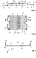
- a rectangular housing 1 which has a relatively flat opening.
- a light unit 3 for generating a tail light function and a retroreflector unit 4 is arranged in a central region 2.
- On opposite sides of the lighting unit 3 further light units are arranged with a strip-shaped light-emitting surface.
- a brake light unit 5 for generating a brake light is arranged at a front end of the housing 1. Adjacent to the brake light unit 5, a flashing light unit 6 is arranged to generate a direction indicator.
- a rear fog lamp unit (7) for generating a rear fog light, and adjacent to the same a reverse lamp unit for generating a reversing light is arranged.
- the lighting unit 3 for generating the tail light has the surface radiation of the same a surface light guide 9 as a light guide.
- the surface light guide 9 also serves as an optical unit for the lighting unit 3.
- the surface light guide 9 is rectangular in shape and has a front flat sides 10 arranged at the front in the main emission direction H of the illumination device and a rear flat side 11 arranged at the rear in the main emission direction H. On opposite sides, close to the flat sides 10, 11, a Lichteinkoppelabêt 12 of the surface light guide 9, which is arcuate.
- the Lichteinkoppelabites 12 allows a 90-degree deflection of the surface light guide 9 at one edge thereof, so that via a arranged at a free end of the Lichteinkoppelabitess 12 narrow side 13 of the surface light guide 9, a first light beam L1 of light sources 14 in the surface light guide 9 can be coupled the light sources 14 are arranged in a common plane and have an optical axis A which is parallel to the main emission direction H of the illumination device.
- the light sources 14 associated with the tail lamp unit 3 are arranged in a row R1, R1 '.
- the row R1, R1 'of light sources 14 is parallel to a row R2 of light sources 14 for the brake light unit 5, a row R3 of light sources 4 for the flashing light unit 6, to a row R4 of light sources 14 for the rear fog lamp unit 7 and a row R5 of light sources 14 for the reversing light unit 8.
- the light sources 14 of the rows R1, R2, R3 are arranged on a first printed circuit board 15 and the rows R1 ', R4 and R5 are arranged on a second printed circuit board 16.
- the first printed circuit board 15 and the second printed circuit board 16 are arranged in the housing 1 so as to rest against the bottom thereof.
- the retroreflector unit 4 is arranged, wherein a square housing 17 of the reversing light unit 4 receives a triangular-shaped reflecting surface 18.
- the return beam unit 4 has a greater thickness than the printed circuit boards 15, 16.
- the Lichteinkoppelabête 12 of the surface light guide 9 have such an arc length that the surface light guide 9 with its front and rear flat side 10, 11 covers the return beam unit 4 or in the main radiation direction H. is arranged in front of the return beam unit 4.
- a covering panel 19 is provided which has a square opening 20 in the middle area 2 and openings 21 which are line-shaped at opposite ends.
- the line-shaped openings 21 each have reflector segments 22 adapted to the light sources 14 of the brake light unit 5, the flashing light unit 6, the rear fog light unit 7 and the return beacon light unit.
- the diaphragm 19 is connected via fastening means 23 to the housing 1.
- the lighting device thus formed is completed with a transparent cover disc, not shown.
- the rear flat side 11 of the surface light guide 9 as means for deflecting the coupled via the Lichteinkoppelabêt 12 light L1 a number of scattering optical elements 25, so that when hitting the inside of the surface light guide 9 by total reflection on the front flat side 10 and the rear flat side 11 forwarded light L1 the same deflected towards the front flat side 10 and then over the front Flat side 10 is coupled out in the main emission direction H for generating the tail light function.
- the scattering optical elements 25 are in a checkerboard pattern 26 - as in FIG. 9 is shown schematically - arranged.
- the scattering optical elements 25 are formed as prismatic incisions whose dimension increases with the distance to the Lichteinkoppelabêt 12 up to a center plane M of the surface light guide 9. In this way, a uniform over the surface light emission L1 is possible.
- a stutter-optics-free surface 27 forms on the rear flat side 11, which-like the completely strew-optically free front flat side 10-permits the passage of a second light beam L2.
- the second light beam L2 passes from the outside through the front flat side 10 and the stutter-optics surfaces 27 of the rear flat side 11 of the surface light guide 9, hits the reflecting surface 18 of the return beam unit 4, from which it is reflected in the direction of the surface light guide 9, so that the second light beam L2 through the strew-optic-free surface 27 of the rear flat side 11 and the front flat side 10 exits to the outside to produce the remindstrahlfunktion.
- the strew-optics-free surface 27 of the rear flat side 11 is chosen to be equal to or greater than a minimum retroreflective surface. Furthermore, the retroreflecting surface 18 of the retroreflector unit 4 has a size such that it corresponds to or is greater than the minimum retroreflecting surface. In this way, it is ensured that the required minimum reflectance surface is guaranteed for the reflectance function. It is understood that preferably the dimension of the surface light guide 9 is greater than the dimension of the reflector surface 18.
- the surface light guide 9 is formed as an injection molded part, wherein the scattering optical elements 25 are produced in one step with the surface light guide 9.
- the surface light guide 9 and the reflecting light surface 18 is colored red.
- the scattering optical elements 25 may be formed equally large, the distribution density of the same from the Lichteinkoppelabêt 12 to the center plane M is greater.
- the scattering optical elements 25 may also be applied to the rear flat side 11 of the surface light guide 9 by erosion or by etching or by lasers.
- the scattering optical elements 25 may also be applied by printing or by painting on the rear flat side 11 of the surface light guide 9.
- the means for deflecting the light L1 can also be formed by scattering optical particles which are arranged within the surface light guide 9, ie between the front flat side 10 and the rear flat side 11.
- the distribution of the scattering optical elements is not limited to the rear flat side 11 of the surface light guide 9, as in the previous embodiments.
- the scattering optical particles are formed as nano-particles whose dimensions are in the nm range. These nano-particles are preferably arranged evenly distributed within the surface light guide 9. The nano-particles are arranged in such a concentration within the surface light guide 9, the return radiation that is not reduced by a return radiation of the second light beam L2 through the surface light guide 9 more than by 30%. In this way, the remindstrahlfunktion is secured.
- the surface light guide also of a first material containing the nano-particles and a consist of second material, which is formed nanoparticles free.
- struc- ture-free and struc- ture-containing regions of the surface light guide can be formed so that, for example, a checkerboard pattern of the first and second material is formed in the longitudinal section of the surface light guide.
- This surface light guide can preferably be produced by a two-component injection molding process.
- the light sources 14 are formed as LED light sources. Alternatively, other semiconductor light sources can be used.
- the printed circuit boards 15, 16 are preferably designed as rigid printed circuit boards.
- FIG. 9 schematically the checkerboard pattern 26 of the rear flat side 11 consisting of scattering optical elements 25 and strew-optics surfaces 27 is shown.
- the surface light guide 9 may be formed as a plate, wherein the front flat side and the rear flat side are interconnected by narrow sides.
- the light L1 is not - as in the previous embodiments - coupled in the main emission direction H, but transversely to the main emission direction H in the longitudinal direction of the surface light guide 9.
- the contour of the retroreflector unit 4 is shown, which is smaller than the surface light guide 9.
- the proportions of the stutter-free surfaces 27 covering the retroreflector surface 18 are, however, so large that a retroreflective function is ensured.
- scattering optical elements 25 ' are arranged in strips on the rear flat side 11 of the surface light guide 9.
- the scattering optical elements 25, 25 ' can also be arranged in a different pattern, for example in the form of a check pattern.
- the scattering optical elements themselves can be designed as circular surfaces, triangular or polygonal surfaces or in another form.
- the surface light guide interspersed with the nano-particles appears transparent in transparency or as a slightly diffuse-looking disk without recognizable structure.
- the light When illuminating the surface light guide from the narrow side, the light propagates in the surface under total reflection at the front and rear flat sides and is scattered on the nano-particles, so that the entire surface light conductor lights up uniformly.
- the nanoparticles For the light L2 passing transversely to the surface light guide, the nanoparticles cause only a very small scattering, so that the reflection function is ensured.
- the invention enables the space-saving combination of a passive return beam function with an active lighting function.
- the active lighting function can also be used to generate another light function.
Landscapes
- Engineering & Computer Science (AREA)
- General Engineering & Computer Science (AREA)
- Mechanical Engineering (AREA)
- Physics & Mathematics (AREA)
- Microelectronics & Electronic Packaging (AREA)
- Optics & Photonics (AREA)
- Non-Portable Lighting Devices Or Systems Thereof (AREA)
- Planar Illumination Modules (AREA)
Applications Claiming Priority (2)
| Application Number | Priority Date | Filing Date | Title |
|---|---|---|---|
| DE102013110839.3A DE102013110839A1 (de) | 2013-10-01 | 2013-10-01 | Beleuchtungsvorrichtung für Fahrzeuge |
| PCT/EP2014/071005 WO2015049264A1 (de) | 2013-10-01 | 2014-10-01 | Beleuchtungsvorrichtung für fahrzeuge |
Publications (2)
| Publication Number | Publication Date |
|---|---|
| EP3052852A1 EP3052852A1 (de) | 2016-08-10 |
| EP3052852B1 true EP3052852B1 (de) | 2019-04-03 |
Family
ID=51655739
Family Applications (1)
| Application Number | Title | Priority Date | Filing Date |
|---|---|---|---|
| EP14777621.5A Active EP3052852B1 (de) | 2013-10-01 | 2014-10-01 | Beleuchtungsvorrichtung für fahrzeuge |
Country Status (5)
| Country | Link |
|---|---|
| US (1) | US9915406B2 (zh) |
| EP (1) | EP3052852B1 (zh) |
| CN (1) | CN105793645B (zh) |
| DE (1) | DE102013110839A1 (zh) |
| WO (1) | WO2015049264A1 (zh) |
Families Citing this family (9)
| Publication number | Priority date | Publication date | Assignee | Title |
|---|---|---|---|---|
| TWM549174U (zh) * | 2017-01-12 | 2017-09-21 | Coplus Inc | 汽車尾燈 |
| EP3301355B1 (fr) * | 2016-09-28 | 2024-01-10 | Valeo Vision | Procédé d' obtention d'un ensemble de diffusion de lumière, notamment pour véhicule automobile |
| CN206268997U (zh) * | 2016-12-21 | 2017-06-20 | 麦格纳(太仓)汽车科技有限公司 | 双向入光的光导式汽车高位刹车灯 |
| US10160379B2 (en) * | 2016-12-30 | 2018-12-25 | Valeo North America, Inc. | Integration of side reflex and light pipe side marker |
| DE102017208589B4 (de) * | 2017-05-22 | 2022-02-24 | Volkswagen Aktiengesellschaft | Lichtleiter und Beleuchtungssystem für ein Fahrzeug |
| US11104271B2 (en) * | 2017-08-07 | 2021-08-31 | Zodiac Cabin Controls Gmbh | Area light integrated in a cabin furnishing element |
| CN109695854A (zh) * | 2017-10-20 | 2019-04-30 | 法雷奥照明湖北技术中心有限公司 | 光源组件、照明装置和机动车辆 |
| DE102018125438A1 (de) * | 2018-10-15 | 2020-04-16 | HELLA GmbH & Co. KGaA | Beleuchtungsvorrichtung für Fahrzeuge |
| CN112856330A (zh) * | 2021-01-11 | 2021-05-28 | 马瑞利汽车照明系统(佛山)有限公司 | 一种单光导发光式尾灯光导结构及单光导导光方法 |
Family Cites Families (23)
| Publication number | Priority date | Publication date | Assignee | Title |
|---|---|---|---|---|
| DE719930C (de) | 1940-05-19 | 1942-04-20 | Herm Riemann Fa | Mit Rueckstrahler vereinigtes Schlusslicht beschraenkter Groesse |
| DE1093685C2 (de) | 1958-01-24 | 1962-12-06 | Westfaelische Metall Industrie | Mit einem Rückstrahler vereinigte Fahrzeugleuchte, deren Lichtquelle mit einem Reflektor hinterlegt ist |
| JP3257457B2 (ja) * | 1997-07-31 | 2002-02-18 | 株式会社日立製作所 | 液晶表示装置 |
| DE19818009C2 (de) | 1998-04-22 | 2003-05-22 | Mcgavigan John Ltd | Mehrschicht-Abdeckung für Mehrfachfunktions-Heckleuchten für Straßenfahrzeuge |
| DE29823027U1 (de) * | 1998-12-24 | 1999-03-25 | Johann & Konen Gmbh & Co | Fahrzeugrückleuchte |
| DE10036325A1 (de) | 2000-07-26 | 2002-02-07 | Hella Kg Hueck & Co | Fahrzeugleuchte |
| DE10037005A1 (de) | 2000-07-29 | 2002-02-07 | Hella Kg Hueck & Co | Leuchte für Fahrzeuge |
| US7137718B2 (en) * | 2001-10-31 | 2006-11-21 | 3M Innovative Properties Company | Automotive lamp |
| DE10359182A1 (de) | 2003-12-17 | 2005-07-21 | Hella Kgaa Hueck & Co. | Leuchte für Fahrzeuge |
| US20060061994A1 (en) | 2004-09-22 | 2006-03-23 | Su-Chang Liao | Alert lampshade device |
| DE102005018212A1 (de) * | 2005-04-20 | 2006-10-26 | Hella Kgaa Hueck & Co. | Signalleuchte für Fahrzeuge |
| DE102006007101A1 (de) | 2005-09-12 | 2007-03-22 | Kompled Gmbh & Co. Kg | Heckleuchtenanordnung, insbesondere für Nutzfahrzeuge |
| FR2894321B1 (fr) | 2005-12-02 | 2010-04-16 | Peugeot Citroen Automobiles Sa | Dispositif lumineux pour un projecteur d'un vehicule automobile et projecteur pour un vehicule automobile comportant un tel dispositif |
| FR2926504B1 (fr) | 2008-01-18 | 2010-08-20 | Peugeot Citroen Automobiles Sa | Element de bloc optique arriere de vehicule automobile, constituant un catadioptre a lentilles de diffusion et a retro-eclairage |
| JP5681104B2 (ja) * | 2008-07-10 | 2015-03-04 | スリーエム イノベイティブ プロパティズ カンパニー | 粘弾性導光体を有する再帰反射物品及びデバイス |
| DE102008048751A1 (de) * | 2008-09-25 | 2010-04-01 | Automotive Lighting Reutlingen Gmbh | Leuchte für Kraftfahrzeuge |
| DE102009035741A1 (de) * | 2009-08-01 | 2011-02-03 | Automotive Lighting Reutlingen Gmbh | Kraftfahrzeugleuchte |
| DE102009058458B4 (de) * | 2009-12-16 | 2019-09-19 | Automotive Lighting Reutlingen Gmbh | Leuchte für ein Kraftfahrzeug |
| EP2354637B1 (de) | 2010-01-30 | 2020-03-04 | HELLA GmbH & Co. KGaA | Beleuchtungsvorrichtung für Fahrzeuge |
| DE102011016416A1 (de) * | 2011-04-08 | 2012-10-11 | GM Global Technology Operations LLC (n. d. Gesetzen des Staates Delaware) | Kennzeichnungsvorrichtung für ein Fahrzeug und Verfahren zur Herstellung derselben |
| DE102011016440A1 (de) * | 2011-04-08 | 2012-10-11 | GM Global Technology Operations LLC (n. d. Gesetzen des Staates Delaware) | Kennzeichenvorrichtung für ein Fahrzeug und Verfahren zur Herstellung derselben |
| JP5738742B2 (ja) * | 2011-11-09 | 2015-06-24 | 株式会社東芝 | 面光源装置 |
| FR2982658A1 (fr) * | 2011-11-10 | 2013-05-17 | Valeo Vision | Dispositif optique comportant une pluralite de faces reflechissantes |
-
2013
- 2013-10-01 DE DE102013110839.3A patent/DE102013110839A1/de not_active Withdrawn
-
2014
- 2014-10-01 US US15/024,277 patent/US9915406B2/en active Active
- 2014-10-01 EP EP14777621.5A patent/EP3052852B1/de active Active
- 2014-10-01 CN CN201480054662.5A patent/CN105793645B/zh active Active
- 2014-10-01 WO PCT/EP2014/071005 patent/WO2015049264A1/de active Application Filing
Non-Patent Citations (1)
| Title |
|---|
| None * |
Also Published As
| Publication number | Publication date |
|---|---|
| WO2015049264A1 (de) | 2015-04-09 |
| CN105793645B (zh) | 2019-05-28 |
| US20160230950A1 (en) | 2016-08-11 |
| CN105793645A (zh) | 2016-07-20 |
| DE102013110839A1 (de) | 2015-04-02 |
| US9915406B2 (en) | 2018-03-13 |
| EP3052852A1 (de) | 2016-08-10 |
Similar Documents
| Publication | Publication Date | Title |
|---|---|---|
| EP3052852B1 (de) | Beleuchtungsvorrichtung für fahrzeuge | |
| EP1715244B1 (de) | Signalleuchte für Fahrzeuge | |
| DE102005019093B4 (de) | Fahrzeugleuchte mit einem mehrgliedrig gebildeten Lichtleiter | |
| EP1022187B1 (de) | Fahrzeugleuchte | |
| EP2317212B1 (de) | Beleuchtungseinrichtung für ein Kraftfahrzeug | |
| EP1327558A2 (de) | Fahrzeugleuchte | |
| EP3531012B9 (de) | Beleuchtungseinrichtung für kraftfahrzeuge mit einem langgestreckten lichtleiter | |
| WO2006045493A1 (de) | Fahrzeugleuchte | |
| DE102004054732B4 (de) | Lichtleiteranordung | |
| DE202005014267U1 (de) | Fahrzeugleuchte mit einem Lichtleiter mit zentraler Lichteinkopplung | |
| EP2502784B1 (de) | Fahrzeugleuchte, insbesondere zur Beleuchtung des Innenraums des Fahrzeugs | |
| DE102018129596A1 (de) | Beleuchtungsvorrichtung für Fahrzeuge | |
| EP3158260B1 (de) | Kraftfahrzeugbeleuchtungseinrichtung | |
| EP1832902A1 (de) | Flache Leuchtvorrichtung | |
| DE102017114476B4 (de) | Beleuchtungseinrichtung eines Kraftfahrzeugs | |
| DE102018220623A1 (de) | Leuchtenanordnung für ein Fahrzeug | |
| DE10317062A1 (de) | Beleuchtungseinrichtung für Kraftfahrzeuge | |
| DE102017208589B4 (de) | Lichtleiter und Beleuchtungssystem für ein Fahrzeug | |
| DE102012007542B4 (de) | Fahrzeugleuchte mit einer Lichtleiteranordnung | |
| DE102012007541B4 (de) | Lichtleiter für eine Fahrzeugsleuchte und Fahrzeugleuchte mit einem Lichtleiter | |
| DE202017104776U1 (de) | Lichtleiter zur Verwendung in einer Licht abgebenden Vorrichtung eines Fahrzeugs, Licht abgebende Vorrichtung und Fahrzeug | |
| EP3358250B1 (de) | Leuchte mit einer lichtleitplatte mit umlenkstrukturen | |
| DE102020104374B3 (de) | Illuminations-vorrichtung mit homogen ausgeleuchteter langschmaler lichtemissionsfläche | |
| DE102015218134A1 (de) | Leuchten-Lichtmodul für ein Kraftfahrzeug | |
| EP4015897A1 (de) | Signalleuchtvorrichtung oder beleuchtungsvorrichtung für einen kraftfahrzeugscheinwerfer |
Legal Events
| Date | Code | Title | Description |
|---|---|---|---|
| PUAI | Public reference made under article 153(3) epc to a published international application that has entered the european phase |
Free format text: ORIGINAL CODE: 0009012 |
|
| 17P | Request for examination filed |
Effective date: 20160331 |
|
| AK | Designated contracting states |
Kind code of ref document: A1 Designated state(s): AL AT BE BG CH CY CZ DE DK EE ES FI FR GB GR HR HU IE IS IT LI LT LU LV MC MK MT NL NO PL PT RO RS SE SI SK SM TR |
|
| AX | Request for extension of the european patent |
Extension state: BA ME |
|
| DAX | Request for extension of the european patent (deleted) | ||
| RAP1 | Party data changed (applicant data changed or rights of an application transferred) |
Owner name: HELLA GMBH & CO. KGAA |
|
| REG | Reference to a national code |
Ref country code: DE Ref legal event code: R079 Ref document number: 502014011330 Country of ref document: DE Free format text: PREVIOUS MAIN CLASS: F21S0008100000 Ipc: F21S0043140000 |
|
| RIC1 | Information provided on ipc code assigned before grant |
Ipc: B60Q 1/30 20060101ALI20180919BHEP Ipc: F21S 43/249 20180101ALI20180919BHEP Ipc: F21S 43/239 20180101ALI20180919BHEP Ipc: B60Q 1/26 20060101ALI20180919BHEP Ipc: F21S 43/245 20180101ALI20180919BHEP Ipc: B60Q 1/00 20060101ALI20180919BHEP Ipc: F21S 43/14 20180101AFI20180919BHEP Ipc: F21S 43/30 20180101ALI20180919BHEP |
|
| GRAP | Despatch of communication of intention to grant a patent |
Free format text: ORIGINAL CODE: EPIDOSNIGR1 |
|
| STAA | Information on the status of an ep patent application or granted ep patent |
Free format text: STATUS: GRANT OF PATENT IS INTENDED |
|
| INTG | Intention to grant announced |
Effective date: 20181105 |
|
| GRAS | Grant fee paid |
Free format text: ORIGINAL CODE: EPIDOSNIGR3 |
|
| GRAJ | Information related to disapproval of communication of intention to grant by the applicant or resumption of examination proceedings by the epo deleted |
Free format text: ORIGINAL CODE: EPIDOSDIGR1 |
|
| GRAL | Information related to payment of fee for publishing/printing deleted |
Free format text: ORIGINAL CODE: EPIDOSDIGR3 |
|
| STAA | Information on the status of an ep patent application or granted ep patent |
Free format text: STATUS: REQUEST FOR EXAMINATION WAS MADE |
|
| RIC1 | Information provided on ipc code assigned before grant |
Ipc: B60Q 1/30 20060101ALI20180919BHEP Ipc: F21S 43/30 20180101ALI20180919BHEP Ipc: F21S 43/14 20180101AFI20180919BHEP Ipc: F21S 43/249 20180101ALI20180919BHEP Ipc: F21S 43/245 20180101ALI20180919BHEP Ipc: B60Q 1/26 20060101ALI20180919BHEP Ipc: F21S 43/239 20180101ALI20180919BHEP Ipc: B60Q 1/00 20060101ALI20180919BHEP |
|
| GRAR | Information related to intention to grant a patent recorded |
Free format text: ORIGINAL CODE: EPIDOSNIGR71 |
|
| STAA | Information on the status of an ep patent application or granted ep patent |
Free format text: STATUS: GRANT OF PATENT IS INTENDED |
|
| GRAA | (expected) grant |
Free format text: ORIGINAL CODE: 0009210 |
|
| STAA | Information on the status of an ep patent application or granted ep patent |
Free format text: STATUS: THE PATENT HAS BEEN GRANTED |
|
| INTC | Intention to grant announced (deleted) | ||
| AK | Designated contracting states |
Kind code of ref document: B1 Designated state(s): AL AT BE BG CH CY CZ DE DK EE ES FI FR GB GR HR HU IE IS IT LI LT LU LV MC MK MT NL NO PL PT RO RS SE SI SK SM TR |
|
| INTG | Intention to grant announced |
Effective date: 20190226 |
|
| REG | Reference to a national code |
Ref country code: GB Ref legal event code: FG4D Free format text: NOT ENGLISH |
|
| REG | Reference to a national code |
Ref country code: CH Ref legal event code: EP Ref country code: AT Ref legal event code: REF Ref document number: 1116184 Country of ref document: AT Kind code of ref document: T Effective date: 20190415 |
|
| REG | Reference to a national code |
Ref country code: DE Ref legal event code: R096 Ref document number: 502014011330 Country of ref document: DE |
|
| REG | Reference to a national code |
Ref country code: IE Ref legal event code: FG4D Free format text: LANGUAGE OF EP DOCUMENT: GERMAN |
|
| REG | Reference to a national code |
Ref country code: NL Ref legal event code: MP Effective date: 20190403 |
|
| REG | Reference to a national code |
Ref country code: LT Ref legal event code: MG4D |
|
| PG25 | Lapsed in a contracting state [announced via postgrant information from national office to epo] |
Ref country code: NL Free format text: LAPSE BECAUSE OF FAILURE TO SUBMIT A TRANSLATION OF THE DESCRIPTION OR TO PAY THE FEE WITHIN THE PRESCRIBED TIME-LIMIT Effective date: 20190403 |
|
| PG25 | Lapsed in a contracting state [announced via postgrant information from national office to epo] |
Ref country code: CZ Free format text: LAPSE BECAUSE OF FAILURE TO SUBMIT A TRANSLATION OF THE DESCRIPTION OR TO PAY THE FEE WITHIN THE PRESCRIBED TIME-LIMIT Effective date: 20190403 Ref country code: FI Free format text: LAPSE BECAUSE OF FAILURE TO SUBMIT A TRANSLATION OF THE DESCRIPTION OR TO PAY THE FEE WITHIN THE PRESCRIBED TIME-LIMIT Effective date: 20190403 Ref country code: NO Free format text: LAPSE BECAUSE OF FAILURE TO SUBMIT A TRANSLATION OF THE DESCRIPTION OR TO PAY THE FEE WITHIN THE PRESCRIBED TIME-LIMIT Effective date: 20190703 Ref country code: PT Free format text: LAPSE BECAUSE OF FAILURE TO SUBMIT A TRANSLATION OF THE DESCRIPTION OR TO PAY THE FEE WITHIN THE PRESCRIBED TIME-LIMIT Effective date: 20190803 Ref country code: AL Free format text: LAPSE BECAUSE OF FAILURE TO SUBMIT A TRANSLATION OF THE DESCRIPTION OR TO PAY THE FEE WITHIN THE PRESCRIBED TIME-LIMIT Effective date: 20190403 Ref country code: HR Free format text: LAPSE BECAUSE OF FAILURE TO SUBMIT A TRANSLATION OF THE DESCRIPTION OR TO PAY THE FEE WITHIN THE PRESCRIBED TIME-LIMIT Effective date: 20190403 Ref country code: SE Free format text: LAPSE BECAUSE OF FAILURE TO SUBMIT A TRANSLATION OF THE DESCRIPTION OR TO PAY THE FEE WITHIN THE PRESCRIBED TIME-LIMIT Effective date: 20190403 Ref country code: ES Free format text: LAPSE BECAUSE OF FAILURE TO SUBMIT A TRANSLATION OF THE DESCRIPTION OR TO PAY THE FEE WITHIN THE PRESCRIBED TIME-LIMIT Effective date: 20190403 Ref country code: LT Free format text: LAPSE BECAUSE OF FAILURE TO SUBMIT A TRANSLATION OF THE DESCRIPTION OR TO PAY THE FEE WITHIN THE PRESCRIBED TIME-LIMIT Effective date: 20190403 |
|
| PG25 | Lapsed in a contracting state [announced via postgrant information from national office to epo] |
Ref country code: RS Free format text: LAPSE BECAUSE OF FAILURE TO SUBMIT A TRANSLATION OF THE DESCRIPTION OR TO PAY THE FEE WITHIN THE PRESCRIBED TIME-LIMIT Effective date: 20190403 Ref country code: BG Free format text: LAPSE BECAUSE OF FAILURE TO SUBMIT A TRANSLATION OF THE DESCRIPTION OR TO PAY THE FEE WITHIN THE PRESCRIBED TIME-LIMIT Effective date: 20190703 Ref country code: GR Free format text: LAPSE BECAUSE OF FAILURE TO SUBMIT A TRANSLATION OF THE DESCRIPTION OR TO PAY THE FEE WITHIN THE PRESCRIBED TIME-LIMIT Effective date: 20190704 Ref country code: PL Free format text: LAPSE BECAUSE OF FAILURE TO SUBMIT A TRANSLATION OF THE DESCRIPTION OR TO PAY THE FEE WITHIN THE PRESCRIBED TIME-LIMIT Effective date: 20190403 Ref country code: LV Free format text: LAPSE BECAUSE OF FAILURE TO SUBMIT A TRANSLATION OF THE DESCRIPTION OR TO PAY THE FEE WITHIN THE PRESCRIBED TIME-LIMIT Effective date: 20190403 |
|
| PG25 | Lapsed in a contracting state [announced via postgrant information from national office to epo] |
Ref country code: IS Free format text: LAPSE BECAUSE OF FAILURE TO SUBMIT A TRANSLATION OF THE DESCRIPTION OR TO PAY THE FEE WITHIN THE PRESCRIBED TIME-LIMIT Effective date: 20190803 |
|
| REG | Reference to a national code |
Ref country code: DE Ref legal event code: R097 Ref document number: 502014011330 Country of ref document: DE |
|
| PG25 | Lapsed in a contracting state [announced via postgrant information from national office to epo] |
Ref country code: RO Free format text: LAPSE BECAUSE OF FAILURE TO SUBMIT A TRANSLATION OF THE DESCRIPTION OR TO PAY THE FEE WITHIN THE PRESCRIBED TIME-LIMIT Effective date: 20190403 Ref country code: EE Free format text: LAPSE BECAUSE OF FAILURE TO SUBMIT A TRANSLATION OF THE DESCRIPTION OR TO PAY THE FEE WITHIN THE PRESCRIBED TIME-LIMIT Effective date: 20190403 Ref country code: DK Free format text: LAPSE BECAUSE OF FAILURE TO SUBMIT A TRANSLATION OF THE DESCRIPTION OR TO PAY THE FEE WITHIN THE PRESCRIBED TIME-LIMIT Effective date: 20190403 Ref country code: SK Free format text: LAPSE BECAUSE OF FAILURE TO SUBMIT A TRANSLATION OF THE DESCRIPTION OR TO PAY THE FEE WITHIN THE PRESCRIBED TIME-LIMIT Effective date: 20190403 |
|
| PLBE | No opposition filed within time limit |
Free format text: ORIGINAL CODE: 0009261 |
|
| STAA | Information on the status of an ep patent application or granted ep patent |
Free format text: STATUS: NO OPPOSITION FILED WITHIN TIME LIMIT |
|
| PG25 | Lapsed in a contracting state [announced via postgrant information from national office to epo] |
Ref country code: IT Free format text: LAPSE BECAUSE OF FAILURE TO SUBMIT A TRANSLATION OF THE DESCRIPTION OR TO PAY THE FEE WITHIN THE PRESCRIBED TIME-LIMIT Effective date: 20190403 Ref country code: SM Free format text: LAPSE BECAUSE OF FAILURE TO SUBMIT A TRANSLATION OF THE DESCRIPTION OR TO PAY THE FEE WITHIN THE PRESCRIBED TIME-LIMIT Effective date: 20190403 |
|
| 26N | No opposition filed |
Effective date: 20200106 |
|
| PG25 | Lapsed in a contracting state [announced via postgrant information from national office to epo] |
Ref country code: TR Free format text: LAPSE BECAUSE OF FAILURE TO SUBMIT A TRANSLATION OF THE DESCRIPTION OR TO PAY THE FEE WITHIN THE PRESCRIBED TIME-LIMIT Effective date: 20190403 |
|
| PG25 | Lapsed in a contracting state [announced via postgrant information from national office to epo] |
Ref country code: MC Free format text: LAPSE BECAUSE OF FAILURE TO SUBMIT A TRANSLATION OF THE DESCRIPTION OR TO PAY THE FEE WITHIN THE PRESCRIBED TIME-LIMIT Effective date: 20190403 Ref country code: SI Free format text: LAPSE BECAUSE OF FAILURE TO SUBMIT A TRANSLATION OF THE DESCRIPTION OR TO PAY THE FEE WITHIN THE PRESCRIBED TIME-LIMIT Effective date: 20190403 |
|
| REG | Reference to a national code |
Ref country code: CH Ref legal event code: PL |
|
| PG25 | Lapsed in a contracting state [announced via postgrant information from national office to epo] |
Ref country code: LI Free format text: LAPSE BECAUSE OF NON-PAYMENT OF DUE FEES Effective date: 20191031 Ref country code: CH Free format text: LAPSE BECAUSE OF NON-PAYMENT OF DUE FEES Effective date: 20191031 Ref country code: LU Free format text: LAPSE BECAUSE OF NON-PAYMENT OF DUE FEES Effective date: 20191001 |
|
| REG | Reference to a national code |
Ref country code: BE Ref legal event code: MM Effective date: 20191031 |
|
| PG25 | Lapsed in a contracting state [announced via postgrant information from national office to epo] |
Ref country code: BE Free format text: LAPSE BECAUSE OF NON-PAYMENT OF DUE FEES Effective date: 20191031 |
|
| GBPC | Gb: european patent ceased through non-payment of renewal fee |
Effective date: 20191001 |
|
| PG25 | Lapsed in a contracting state [announced via postgrant information from national office to epo] |
Ref country code: GB Free format text: LAPSE BECAUSE OF NON-PAYMENT OF DUE FEES Effective date: 20191001 Ref country code: IE Free format text: LAPSE BECAUSE OF NON-PAYMENT OF DUE FEES Effective date: 20191001 |
|
| REG | Reference to a national code |
Ref country code: AT Ref legal event code: MM01 Ref document number: 1116184 Country of ref document: AT Kind code of ref document: T Effective date: 20191001 |
|
| PG25 | Lapsed in a contracting state [announced via postgrant information from national office to epo] |
Ref country code: AT Free format text: LAPSE BECAUSE OF NON-PAYMENT OF DUE FEES Effective date: 20191001 |
|
| PG25 | Lapsed in a contracting state [announced via postgrant information from national office to epo] |
Ref country code: CY Free format text: LAPSE BECAUSE OF FAILURE TO SUBMIT A TRANSLATION OF THE DESCRIPTION OR TO PAY THE FEE WITHIN THE PRESCRIBED TIME-LIMIT Effective date: 20190403 |
|
| PG25 | Lapsed in a contracting state [announced via postgrant information from national office to epo] |
Ref country code: HU Free format text: LAPSE BECAUSE OF FAILURE TO SUBMIT A TRANSLATION OF THE DESCRIPTION OR TO PAY THE FEE WITHIN THE PRESCRIBED TIME-LIMIT; INVALID AB INITIO Effective date: 20141001 Ref country code: MT Free format text: LAPSE BECAUSE OF FAILURE TO SUBMIT A TRANSLATION OF THE DESCRIPTION OR TO PAY THE FEE WITHIN THE PRESCRIBED TIME-LIMIT Effective date: 20190403 |
|
| PG25 | Lapsed in a contracting state [announced via postgrant information from national office to epo] |
Ref country code: MK Free format text: LAPSE BECAUSE OF FAILURE TO SUBMIT A TRANSLATION OF THE DESCRIPTION OR TO PAY THE FEE WITHIN THE PRESCRIBED TIME-LIMIT Effective date: 20190403 |
|
| PGFP | Annual fee paid to national office [announced via postgrant information from national office to epo] |
Ref country code: FR Payment date: 20230911 Year of fee payment: 10 |
|
| PGFP | Annual fee paid to national office [announced via postgrant information from national office to epo] |
Ref country code: DE Payment date: 20230830 Year of fee payment: 10 |