EP3052852B1 - Lighting device for vehicles - Google Patents
Lighting device for vehicles Download PDFInfo
- Publication number
- EP3052852B1 EP3052852B1 EP14777621.5A EP14777621A EP3052852B1 EP 3052852 B1 EP3052852 B1 EP 3052852B1 EP 14777621 A EP14777621 A EP 14777621A EP 3052852 B1 EP3052852 B1 EP 3052852B1
- Authority
- EP
- European Patent Office
- Prior art keywords
- light guide
- light
- low profile
- lighting device
- flat side
- Prior art date
- Legal status (The legal status is an assumption and is not a legal conclusion. Google has not performed a legal analysis and makes no representation as to the accuracy of the status listed.)
- Active
Links
- 230000003287 optical effect Effects 0.000 claims description 46
- 239000002105 nanoparticle Substances 0.000 claims description 16
- 230000005855 radiation Effects 0.000 claims description 10
- 239000000463 material Substances 0.000 claims description 7
- 239000002245 particle Substances 0.000 claims description 6
- 238000001746 injection moulding Methods 0.000 claims description 4
- 238000007639 printing Methods 0.000 claims description 4
- 230000008878 coupling Effects 0.000 claims description 3
- 238000010168 coupling process Methods 0.000 claims description 3
- 238000005859 coupling reaction Methods 0.000 claims description 3
- 230000003628 erosive effect Effects 0.000 claims description 3
- 238000005530 etching Methods 0.000 claims description 3
- 238000010422 painting Methods 0.000 claims description 3
- 230000011514 reflex Effects 0.000 claims 12
- 238000009792 diffusion process Methods 0.000 claims 10
- 239000006185 dispersion Substances 0.000 claims 1
- 239000013307 optical fiber Substances 0.000 description 6
- 208000003028 Stuttering Diseases 0.000 description 4
- 239000004020 conductor Substances 0.000 description 3
- 238000009826 distribution Methods 0.000 description 3
- 230000008901 benefit Effects 0.000 description 2
- 239000013078 crystal Substances 0.000 description 2
- 238000005286 illumination Methods 0.000 description 2
- 238000000149 argon plasma sintering Methods 0.000 description 1
- 238000010276 construction Methods 0.000 description 1
- 230000009977 dual effect Effects 0.000 description 1
- 230000000694 effects Effects 0.000 description 1
- 238000002347 injection Methods 0.000 description 1
- 239000007924 injection Substances 0.000 description 1
- 238000003754 machining Methods 0.000 description 1
- 238000004519 manufacturing process Methods 0.000 description 1
- 239000004065 semiconductor Substances 0.000 description 1
- 239000013585 weight reducing agent Substances 0.000 description 1
Images


Classifications
-
- F—MECHANICAL ENGINEERING; LIGHTING; HEATING; WEAPONS; BLASTING
- F21—LIGHTING
- F21S—NON-PORTABLE LIGHTING DEVICES; SYSTEMS THEREOF; VEHICLE LIGHTING DEVICES SPECIALLY ADAPTED FOR VEHICLE EXTERIORS
- F21S43/00—Signalling devices specially adapted for vehicle exteriors, e.g. brake lamps, direction indicator lights or reversing lights
- F21S43/20—Signalling devices specially adapted for vehicle exteriors, e.g. brake lamps, direction indicator lights or reversing lights characterised by refractors, transparent cover plates, light guides or filters
- F21S43/235—Light guides
- F21S43/236—Light guides characterised by the shape of the light guide
- F21S43/239—Light guides characterised by the shape of the light guide plate-shaped
-
- B—PERFORMING OPERATIONS; TRANSPORTING
- B60—VEHICLES IN GENERAL
- B60Q—ARRANGEMENT OF SIGNALLING OR LIGHTING DEVICES, THE MOUNTING OR SUPPORTING THEREOF OR CIRCUITS THEREFOR, FOR VEHICLES IN GENERAL
- B60Q1/00—Arrangement of optical signalling or lighting devices, the mounting or supporting thereof or circuits therefor
- B60Q1/0029—Spatial arrangement
- B60Q1/0041—Spatial arrangement of several lamps in relation to each other
- B60Q1/0058—Stacked, i.e. one lamp located behind the other in the optical axis direction
-
- B—PERFORMING OPERATIONS; TRANSPORTING
- B60—VEHICLES IN GENERAL
- B60Q—ARRANGEMENT OF SIGNALLING OR LIGHTING DEVICES, THE MOUNTING OR SUPPORTING THEREOF OR CIRCUITS THEREFOR, FOR VEHICLES IN GENERAL
- B60Q1/00—Arrangement of optical signalling or lighting devices, the mounting or supporting thereof or circuits therefor
- B60Q1/26—Arrangement of optical signalling or lighting devices, the mounting or supporting thereof or circuits therefor the devices being primarily intended to indicate the vehicle, or parts thereof, or to give signals, to other traffic
- B60Q1/2607—Arrangement of optical signalling or lighting devices, the mounting or supporting thereof or circuits therefor the devices being primarily intended to indicate the vehicle, or parts thereof, or to give signals, to other traffic comprising at least two indicating lamps
-
- B—PERFORMING OPERATIONS; TRANSPORTING
- B60—VEHICLES IN GENERAL
- B60Q—ARRANGEMENT OF SIGNALLING OR LIGHTING DEVICES, THE MOUNTING OR SUPPORTING THEREOF OR CIRCUITS THEREFOR, FOR VEHICLES IN GENERAL
- B60Q1/00—Arrangement of optical signalling or lighting devices, the mounting or supporting thereof or circuits therefor
- B60Q1/26—Arrangement of optical signalling or lighting devices, the mounting or supporting thereof or circuits therefor the devices being primarily intended to indicate the vehicle, or parts thereof, or to give signals, to other traffic
- B60Q1/30—Arrangement of optical signalling or lighting devices, the mounting or supporting thereof or circuits therefor the devices being primarily intended to indicate the vehicle, or parts thereof, or to give signals, to other traffic for indicating rear of vehicle, e.g. by means of reflecting surfaces
- B60Q1/301—Arrangement of optical signalling or lighting devices, the mounting or supporting thereof or circuits therefor the devices being primarily intended to indicate the vehicle, or parts thereof, or to give signals, to other traffic for indicating rear of vehicle, e.g. by means of reflecting surfaces by means of surfaces, e.g. metal plate, reflecting the light of an external light source
- B60Q1/3015—Arrangement of optical signalling or lighting devices, the mounting or supporting thereof or circuits therefor the devices being primarily intended to indicate the vehicle, or parts thereof, or to give signals, to other traffic for indicating rear of vehicle, e.g. by means of reflecting surfaces by means of surfaces, e.g. metal plate, reflecting the light of an external light source combined with a lamp
-
- F—MECHANICAL ENGINEERING; LIGHTING; HEATING; WEAPONS; BLASTING
- F21—LIGHTING
- F21S—NON-PORTABLE LIGHTING DEVICES; SYSTEMS THEREOF; VEHICLE LIGHTING DEVICES SPECIALLY ADAPTED FOR VEHICLE EXTERIORS
- F21S43/00—Signalling devices specially adapted for vehicle exteriors, e.g. brake lamps, direction indicator lights or reversing lights
- F21S43/10—Signalling devices specially adapted for vehicle exteriors, e.g. brake lamps, direction indicator lights or reversing lights characterised by the light source
- F21S43/13—Signalling devices specially adapted for vehicle exteriors, e.g. brake lamps, direction indicator lights or reversing lights characterised by the light source characterised by the type of light source
- F21S43/14—Light emitting diodes [LED]
-
- F—MECHANICAL ENGINEERING; LIGHTING; HEATING; WEAPONS; BLASTING
- F21—LIGHTING
- F21S—NON-PORTABLE LIGHTING DEVICES; SYSTEMS THEREOF; VEHICLE LIGHTING DEVICES SPECIALLY ADAPTED FOR VEHICLE EXTERIORS
- F21S43/00—Signalling devices specially adapted for vehicle exteriors, e.g. brake lamps, direction indicator lights or reversing lights
- F21S43/20—Signalling devices specially adapted for vehicle exteriors, e.g. brake lamps, direction indicator lights or reversing lights characterised by refractors, transparent cover plates, light guides or filters
- F21S43/235—Light guides
- F21S43/242—Light guides characterised by the emission area
- F21S43/245—Light guides characterised by the emission area emitting light from one or more of its major surfaces
-
- F—MECHANICAL ENGINEERING; LIGHTING; HEATING; WEAPONS; BLASTING
- F21—LIGHTING
- F21S—NON-PORTABLE LIGHTING DEVICES; SYSTEMS THEREOF; VEHICLE LIGHTING DEVICES SPECIALLY ADAPTED FOR VEHICLE EXTERIORS
- F21S43/00—Signalling devices specially adapted for vehicle exteriors, e.g. brake lamps, direction indicator lights or reversing lights
- F21S43/20—Signalling devices specially adapted for vehicle exteriors, e.g. brake lamps, direction indicator lights or reversing lights characterised by refractors, transparent cover plates, light guides or filters
- F21S43/235—Light guides
- F21S43/249—Light guides with two or more light sources being coupled into the light guide
-
- F—MECHANICAL ENGINEERING; LIGHTING; HEATING; WEAPONS; BLASTING
- F21—LIGHTING
- F21S—NON-PORTABLE LIGHTING DEVICES; SYSTEMS THEREOF; VEHICLE LIGHTING DEVICES SPECIALLY ADAPTED FOR VEHICLE EXTERIORS
- F21S43/00—Signalling devices specially adapted for vehicle exteriors, e.g. brake lamps, direction indicator lights or reversing lights
- F21S43/30—Signalling devices specially adapted for vehicle exteriors, e.g. brake lamps, direction indicator lights or reversing lights characterised by reflectors
-
- B—PERFORMING OPERATIONS; TRANSPORTING
- B60—VEHICLES IN GENERAL
- B60Q—ARRANGEMENT OF SIGNALLING OR LIGHTING DEVICES, THE MOUNTING OR SUPPORTING THEREOF OR CIRCUITS THEREFOR, FOR VEHICLES IN GENERAL
- B60Q1/00—Arrangement of optical signalling or lighting devices, the mounting or supporting thereof or circuits therefor
- B60Q1/26—Arrangement of optical signalling or lighting devices, the mounting or supporting thereof or circuits therefor the devices being primarily intended to indicate the vehicle, or parts thereof, or to give signals, to other traffic
- B60Q1/30—Arrangement of optical signalling or lighting devices, the mounting or supporting thereof or circuits therefor the devices being primarily intended to indicate the vehicle, or parts thereof, or to give signals, to other traffic for indicating rear of vehicle, e.g. by means of reflecting surfaces
- B60Q1/303—Rear fog lamps
Definitions
- the invention relates to a lighting device for vehicles according to the preamble of patent claim 1.
- a lighting device for vehicles which has a lighting unit for generating a predetermined light function and a retroreflector unit for generating a reflected light function.
- the lighting unit has as an optical unit a plurality of rod-shaped optical fibers, on which light sources are arranged on the front side. At a rear in the main emission direction of the rod-shaped optical waveguide stray optical elements are arranged so that it meets deflected coupled light in the main radiation and exits at a front lateral surface of the rod-shaped light guide.
- the retroreflective unit has a plurality of strip-shaped reflecting surfaces, which are arranged between the rod-shaped optical fibers of the lighting unit. The return surfaces are connected to the adjacent rod-shaped optical fibers, so that the number of components can be reduced.
- the lighting unit and the back-jet unit are thus arranged substantially next to each other.
- a lighting device for vehicles which has a lighting unit for generating a predetermined light function and a return beam unit for generating a reflection function.
- the rear-beam unit is arranged in the main emission direction in front of a rod-shaped light guide of the lighting unit.
- the light guide is part of an optical unit which additionally has a reflector to which the light coupled out via a lateral surface of the light guide is guided and then emitted by means of the reflector in the main emission direction past the return light unit.
- an enlargement of the luminous area to produce the light function can be effected by means of the reflector.
- the surface of the back-jet unit must be left out here.
- a lighting device for vehicles with a light source and a flat rear-jet unit is known, which is arranged laterally offset from the light source.
- a surface light guide for generating a light function is not provided here.
- a lighting device for vehicles with a light source and a return beam unit wherein the return beam unit has scattering optical elements and stutter-optics surfaces.
- the streuoptikelle surfaces serve as a light passage of a first light beam generated by the light source for generating the light function.
- a surface light guide according to the invention which serves to distribute narrow-side coupled-in light and decouple the light at certain points on the front side to produce the light function is not disclosed there. Instead, streak-free surfaces are used in the rear-beam unit to pass the first light bundle through the flat rear-jet unit.
- a lighting device for vehicles with a light source and a surface light guide wherein the surface light guide comprises at edge portions scattering optical elements.
- the scattering optical elements cause the light to exit at this point.
- An additional return unit is not provided.
- a lighting device for vehicles with a surface light guide is known, on whose narrow side a first light beam is coupled.
- scattering optical elements are arranged so that the injected light can be totally reflected towards an opposite front flat side and coupled to the front flat side to produce a light function.
- the scattering optical elements on the rear flat side serve to totally reflect an externally incident light beam, which is coupled in on the front flat side, so that it can emerge again on the front flat side. As a result, a retroreflective function can be achieved.
- Object of the present invention is therefore to develop a lighting device for vehicles with an integrated back-jet unit such that easy on Way a space-saving provision of a light and/strahlfunktion is guaranteed.
- the particular advantage of the invention is that by providing a light guide of a lighting unit as a surface light guide, a functional surface is provided which can be used both for the light function and for the reflection function.
- the rear-beam unit is arranged in the main emission direction behind the surface light guide. Since the surface light guide has means for deflecting the coupled-in light only to a limited extent, it can not only decouple a first light bundle in the main emission direction to produce the light function but also transmit a second light bundle between a front and rear flat side of the flat light conductor for the re-radiation function. Due to the dual use of the functional space for the lighting and rinsestrahlmaschine the light unit can be made smaller. In addition, this can also be accompanied by a weight reduction of the lighting device.
- scattering optical elements are provided as means for deflecting the light coupled into the surface light guide, which are arranged on a rear flat side of the surface light guide.
- the scattering optical elements are introduced only partially on the rear flat side, so that the reflection function is always given over crystal clear or streuoptiktransport areas of the surface light guide.
- the scattering optical elements can already be formed with the production of the surface light guide.
- the scattering optical elements distributed according to a predetermined pattern over the rear flat side of the surface light guide are arranged. In this way, both a homogeneous light emission and a homogeneous re-radiation can take place.
- the scattering optical elements are arranged distributed over the rear flat side of the surface light guide according to a striped pattern or a checkerboard pattern.
- a homogeneous light emission or retroreflective function can be provided.
- the scattering optical elements are applied by erosion or by etching or by lasers on the rear flat side of the surface light guide.
- the scattering optical elements can be applied in a simple manner.
- the scattering optical elements are by printing or by painting on the rear flat side of the surface light guide applied.
- this can subsequently be applied to a desired pattern.
- scattering optical particles are arranged distributed as means for deflecting the coupled-in light within the surface light guide.
- the scattering optical particles are formed as nano-particles, so that the surface light guide is perceived in the non-operating state of the lighting unit as a crystal clear or only slightly diffuse disk, so that the reflection function is ensured. If the lighting unit is in the operating state, the light propagates in the surface of the surface light guide and is scattered on the nano-particles, so that the entire surface of the surface light guide lights up.
- the surface light conductor illuminates uniformly over its entire surface. There is no need to apply an optical structure or printing adapted to the retroreflective function.
- the nano-particles are essentially effective only for the edge-side light coupling into the optical fiber and the light emission generated by the nano-particles from the optical fiber, while only a small scattering effect in a continuous through the surface of the optical fiber light beam (L2) for the remindstrahlerfunktion own and the reflector function is thereby reduced only slightly.
- the surface light guide may consist of a first material containing nano-particles and a nanoparticle-free second material. In the operating state of the lighting unit, only surface areas of the surface light guide which have nanoparticles light up. It is thus possible to create a pattern of light scattering along the surface light guide, as provided when machining the rear side of the surface light guide according to the other embodiment of the invention.
- the surface light guide on the edge side an arcuate Lichteinkoppelabites, which are associated with a plurality of light sources.
- the light sources can be arranged perpendicular to the main emission in a plane.
- the light sources can be arranged on a printed circuit board which is equipped with further light sources for generating further light functions.
- this can be cost-saving several light functions are provided in the area.
- the lighting device can thereby have a relatively flat and compact construction.
- the back-beam unit has a reflecting surface of such size and the surface light guide streuoptikget surfaces of such size, which is at least as large as a minimum sunlight
- the surface light guide is produced by injection molding, wherein scattering optical elements are formed with increasing distance to the Lichteinkoppelabêt larger or in a higher distribution density.
- the surface light guide can be produced together with the scattering optical elements in one step. Due to the fact that the scattering gradually increases with increasing distance from the light coupling, a homogeneous emission of the light functions can be ensured.
- a lighting device according to the invention can be used, for example, as a tail light for trucks or trailers. Alternatively, the lighting device can also be used in rear lights of passenger cars.
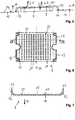
- a rectangular housing 1 which has a relatively flat opening.
- a light unit 3 for generating a tail light function and a retroreflector unit 4 is arranged in a central region 2.
- On opposite sides of the lighting unit 3 further light units are arranged with a strip-shaped light-emitting surface.
- a brake light unit 5 for generating a brake light is arranged at a front end of the housing 1. Adjacent to the brake light unit 5, a flashing light unit 6 is arranged to generate a direction indicator.
- a rear fog lamp unit (7) for generating a rear fog light, and adjacent to the same a reverse lamp unit for generating a reversing light is arranged.
- the lighting unit 3 for generating the tail light has the surface radiation of the same a surface light guide 9 as a light guide.
- the surface light guide 9 also serves as an optical unit for the lighting unit 3.
- the surface light guide 9 is rectangular in shape and has a front flat sides 10 arranged at the front in the main emission direction H of the illumination device and a rear flat side 11 arranged at the rear in the main emission direction H. On opposite sides, close to the flat sides 10, 11, a Lichteinkoppelabêt 12 of the surface light guide 9, which is arcuate.
- the Lichteinkoppelabites 12 allows a 90-degree deflection of the surface light guide 9 at one edge thereof, so that via a arranged at a free end of the Lichteinkoppelabitess 12 narrow side 13 of the surface light guide 9, a first light beam L1 of light sources 14 in the surface light guide 9 can be coupled the light sources 14 are arranged in a common plane and have an optical axis A which is parallel to the main emission direction H of the illumination device.
- the light sources 14 associated with the tail lamp unit 3 are arranged in a row R1, R1 '.
- the row R1, R1 'of light sources 14 is parallel to a row R2 of light sources 14 for the brake light unit 5, a row R3 of light sources 4 for the flashing light unit 6, to a row R4 of light sources 14 for the rear fog lamp unit 7 and a row R5 of light sources 14 for the reversing light unit 8.
- the light sources 14 of the rows R1, R2, R3 are arranged on a first printed circuit board 15 and the rows R1 ', R4 and R5 are arranged on a second printed circuit board 16.
- the first printed circuit board 15 and the second printed circuit board 16 are arranged in the housing 1 so as to rest against the bottom thereof.
- the retroreflector unit 4 is arranged, wherein a square housing 17 of the reversing light unit 4 receives a triangular-shaped reflecting surface 18.
- the return beam unit 4 has a greater thickness than the printed circuit boards 15, 16.
- the Lichteinkoppelabête 12 of the surface light guide 9 have such an arc length that the surface light guide 9 with its front and rear flat side 10, 11 covers the return beam unit 4 or in the main radiation direction H. is arranged in front of the return beam unit 4.
- a covering panel 19 is provided which has a square opening 20 in the middle area 2 and openings 21 which are line-shaped at opposite ends.
- the line-shaped openings 21 each have reflector segments 22 adapted to the light sources 14 of the brake light unit 5, the flashing light unit 6, the rear fog light unit 7 and the return beacon light unit.
- the diaphragm 19 is connected via fastening means 23 to the housing 1.
- the lighting device thus formed is completed with a transparent cover disc, not shown.
- the rear flat side 11 of the surface light guide 9 as means for deflecting the coupled via the Lichteinkoppelabêt 12 light L1 a number of scattering optical elements 25, so that when hitting the inside of the surface light guide 9 by total reflection on the front flat side 10 and the rear flat side 11 forwarded light L1 the same deflected towards the front flat side 10 and then over the front Flat side 10 is coupled out in the main emission direction H for generating the tail light function.
- the scattering optical elements 25 are in a checkerboard pattern 26 - as in FIG. 9 is shown schematically - arranged.
- the scattering optical elements 25 are formed as prismatic incisions whose dimension increases with the distance to the Lichteinkoppelabêt 12 up to a center plane M of the surface light guide 9. In this way, a uniform over the surface light emission L1 is possible.
- a stutter-optics-free surface 27 forms on the rear flat side 11, which-like the completely strew-optically free front flat side 10-permits the passage of a second light beam L2.
- the second light beam L2 passes from the outside through the front flat side 10 and the stutter-optics surfaces 27 of the rear flat side 11 of the surface light guide 9, hits the reflecting surface 18 of the return beam unit 4, from which it is reflected in the direction of the surface light guide 9, so that the second light beam L2 through the strew-optic-free surface 27 of the rear flat side 11 and the front flat side 10 exits to the outside to produce the remindstrahlfunktion.
- the strew-optics-free surface 27 of the rear flat side 11 is chosen to be equal to or greater than a minimum retroreflective surface. Furthermore, the retroreflecting surface 18 of the retroreflector unit 4 has a size such that it corresponds to or is greater than the minimum retroreflecting surface. In this way, it is ensured that the required minimum reflectance surface is guaranteed for the reflectance function. It is understood that preferably the dimension of the surface light guide 9 is greater than the dimension of the reflector surface 18.
- the surface light guide 9 is formed as an injection molded part, wherein the scattering optical elements 25 are produced in one step with the surface light guide 9.
- the surface light guide 9 and the reflecting light surface 18 is colored red.
- the scattering optical elements 25 may be formed equally large, the distribution density of the same from the Lichteinkoppelabêt 12 to the center plane M is greater.
- the scattering optical elements 25 may also be applied to the rear flat side 11 of the surface light guide 9 by erosion or by etching or by lasers.
- the scattering optical elements 25 may also be applied by printing or by painting on the rear flat side 11 of the surface light guide 9.
- the means for deflecting the light L1 can also be formed by scattering optical particles which are arranged within the surface light guide 9, ie between the front flat side 10 and the rear flat side 11.
- the distribution of the scattering optical elements is not limited to the rear flat side 11 of the surface light guide 9, as in the previous embodiments.
- the scattering optical particles are formed as nano-particles whose dimensions are in the nm range. These nano-particles are preferably arranged evenly distributed within the surface light guide 9. The nano-particles are arranged in such a concentration within the surface light guide 9, the return radiation that is not reduced by a return radiation of the second light beam L2 through the surface light guide 9 more than by 30%. In this way, the remindstrahlfunktion is secured.
- the surface light guide also of a first material containing the nano-particles and a consist of second material, which is formed nanoparticles free.
- struc- ture-free and struc- ture-containing regions of the surface light guide can be formed so that, for example, a checkerboard pattern of the first and second material is formed in the longitudinal section of the surface light guide.
- This surface light guide can preferably be produced by a two-component injection molding process.
- the light sources 14 are formed as LED light sources. Alternatively, other semiconductor light sources can be used.
- the printed circuit boards 15, 16 are preferably designed as rigid printed circuit boards.
- FIG. 9 schematically the checkerboard pattern 26 of the rear flat side 11 consisting of scattering optical elements 25 and strew-optics surfaces 27 is shown.
- the surface light guide 9 may be formed as a plate, wherein the front flat side and the rear flat side are interconnected by narrow sides.
- the light L1 is not - as in the previous embodiments - coupled in the main emission direction H, but transversely to the main emission direction H in the longitudinal direction of the surface light guide 9.
- the contour of the retroreflector unit 4 is shown, which is smaller than the surface light guide 9.
- the proportions of the stutter-free surfaces 27 covering the retroreflector surface 18 are, however, so large that a retroreflective function is ensured.
- scattering optical elements 25 ' are arranged in strips on the rear flat side 11 of the surface light guide 9.
- the scattering optical elements 25, 25 ' can also be arranged in a different pattern, for example in the form of a check pattern.
- the scattering optical elements themselves can be designed as circular surfaces, triangular or polygonal surfaces or in another form.
- the surface light guide interspersed with the nano-particles appears transparent in transparency or as a slightly diffuse-looking disk without recognizable structure.
- the light When illuminating the surface light guide from the narrow side, the light propagates in the surface under total reflection at the front and rear flat sides and is scattered on the nano-particles, so that the entire surface light conductor lights up uniformly.
- the nanoparticles For the light L2 passing transversely to the surface light guide, the nanoparticles cause only a very small scattering, so that the reflection function is ensured.
- the invention enables the space-saving combination of a passive return beam function with an active lighting function.
- the active lighting function can also be used to generate another light function.
Description
Die Erfindung betrifft eine Beleuchtungsvorrichtung für Fahrzeuge nach dem Oberbegriff des Patentanspruchs 1.The invention relates to a lighting device for vehicles according to the preamble of
Aus der
Aus der
Vorteilhaft kann mittels des Reflektors eine Vergrößerung der Leuchtfläche zur Erzeugung der Lichtfunktion bewirkt werden. Die Fläche der Rückstrahleinheit muss hierbei jedoch ausgespart bleiben.Advantageously, an enlargement of the luminous area to produce the light function can be effected by means of the reflector. However, the surface of the back-jet unit must be left out here.
Aus der
Aus der
Aus der
Aus der
Aufgabe der vorliegenden Erfindung ist es daher, eine Beleuchtungsvorrichtung für Fahrzeuge mit einer integrierten Rückstrahleinheit derart weiterzubilden, dass auf einfache Weise eine platzsparende Bereitstellung einer Licht- und Rückstrahlfunktion gewährleistet ist.Object of the present invention is therefore to develop a lighting device for vehicles with an integrated back-jet unit such that easy on Way a space-saving provision of a light and Rückstrahlfunktion is guaranteed.
Zur Lösung dieser Aufgabe ist die Erfindung die Merkmale des Patentanspruches 1 auf.To solve this problem, the invention, the features of
Der besondere Vorteil der Erfindung besteht darin, dass durch Ausgestaltung eines Lichtleiters einer Leuchteinheit als Flächenlichtleiter eine Funktionsfläche bereitgestellt wird, die sowohl für die Lichtfunktion als auch für die Rückstrahlfunktion genutzt werden kann. Die Rückstrahleinheit ist in Hauptabstrahlrichtung hinter dem Flächenlichtleiter angeordnet. Da der Flächenlichtleiter nur in einem begrenzten Umfang Mittel zur Umlenkung des eingekoppelten Lichtes aufweist, kann dieser nicht nur ein erstes Lichtbündel in Hauptabstrahlrichtung zur Erzeugung der Lichtfunktion auskoppeln, sondern auch ein zweites Lichtbündel zwischen einer vorderen und hinteren Flachseite des Flachlichtleiters durchlassen für die Rückstrahlfunktion. Aufgrund der Doppelnutzung des Funktionsraumes für die Leucht- und Rückstrahlfunktion kann die Leuchteinheit verkleinert ausgebildet sein. Darüber hinaus kann hierdurch auch eine Gewichtsreduktion der Beleuchtungsvorrichtung einhergehen. Nach der Erfindung sind als Mittel zur Umlenkung des in den Flächenlichtleiter eingekoppelten Lichtes Streuoptikelemente vorgesehen, die an einer hinteren Flachseite des Flächenlichtleiters angeordnet sind. Die Streuoptikelemente sind nur partiell an der hinteren Flachseite eingebracht, so dass über glasklare bzw. streuoptikfreie Bereiche des Flächenlichtleiters die Rückstrahlfunktion stets gegeben ist. Vorteilhaft können die Streuoptikelemente bereits mit Herstellung des Flächenlichtleiters ausgeformt werden.The particular advantage of the invention is that by providing a light guide of a lighting unit as a surface light guide, a functional surface is provided which can be used both for the light function and for the reflection function. The rear-beam unit is arranged in the main emission direction behind the surface light guide. Since the surface light guide has means for deflecting the coupled-in light only to a limited extent, it can not only decouple a first light bundle in the main emission direction to produce the light function but also transmit a second light bundle between a front and rear flat side of the flat light conductor for the re-radiation function. Due to the dual use of the functional space for the lighting and Rückstrahlfunktion the light unit can be made smaller. In addition, this can also be accompanied by a weight reduction of the lighting device. According to the invention, scattering optical elements are provided as means for deflecting the light coupled into the surface light guide, which are arranged on a rear flat side of the surface light guide. The scattering optical elements are introduced only partially on the rear flat side, so that the reflection function is always given over crystal clear or streuoptikfreie areas of the surface light guide. Advantageously, the scattering optical elements can already be formed with the production of the surface light guide.
Nach einer Weiterbildung der Erfindung sind die Streuoptikelemente entsprechend einem vorgegebenen Muster verteilt über die hinterer Flachseite des Flächenlichtleiters angeordnet. Auf diese Weise kann sowohl eine homogene Lichtabstrahlung als auch eine homogene Rückstrahlung erfolgen.According to a development of the invention, the scattering optical elements distributed according to a predetermined pattern over the rear flat side of the surface light guide are arranged. In this way, both a homogeneous light emission and a homogeneous re-radiation can take place.
Nach einer Weiterbildung der Erfindung sind die Streuoptikelemente entsprechend einem Streifenmuster oder einem Schachbrettmuster verteilt über die hintere Flachseite des Flächenlichtleiters angeordnet. Durch eine regelmäßige und/oder gleich verteilte Anordnung der Streuoptikelemente kann eine homogene Lichtabstrahlung bzw. Rückstrahlfunktion bereitgestellt werden.According to a development of the invention, the scattering optical elements are arranged distributed over the rear flat side of the surface light guide according to a striped pattern or a checkerboard pattern. By a regular and / or evenly distributed arrangement of the scattering optical elements, a homogeneous light emission or retroreflective function can be provided.
Nach einer Weiterbildung der Erfindung sind die Streuoptikelemente durch Erodieren oder durch Ätzen oder durch Lasern auf der hinteren Flachseite des Flächenlichtleiters aufgebracht. Hierdurch können auf einfache Weise die Streuoptikelemente aufgebracht werden.According to a development of the invention, the scattering optical elements are applied by erosion or by etching or by lasers on the rear flat side of the surface light guide. As a result, the scattering optical elements can be applied in a simple manner.
Nach einer weiteren Ausführungsform der Erfindung sind die Streuoptikelemente durch Bedruckung oder durch Lackieren auf der hinteren Flachseite des Flächenlichtleiters aufgebracht. Vorteilhaft kann hierdurch nachträglich eine gewünschtes Muster aufgebracht werden.According to a further embodiment of the invention, the scattering optical elements are by printing or by painting on the rear flat side of the surface light guide applied. Advantageously, this can subsequently be applied to a desired pattern.
Nach einer weiteren Ausführungsform der Erfindung sind als Mittel zur Umlenkung des eingekoppelten Lichtes innerhalb des Flächenlichtleiters Streuoptikpartikel verteilt angeordnet. Vorzugsweise sind die Streuoptikpartikel als Nano-Partikel ausgebildet, so dass der Flächenlichtleiter im Nichtbetriebszustand der Leuchteinheit als glasklare oder nur sehr leicht diffuse Scheibe wahrgenommen wird, so dass die Rückstrahlfunktion gewährleistet ist. Befindet sich die Leuchteinheit im Betriebszustand, breitet sich das Licht in der Fläche des Flächenlichtleiters aus und wird an den Nano-Partikeln gestreut, so dass die gesamte Fläche des Flächenlichtleiters aufleuchtet. Vorteilhaft leuchtet der Flächenlichtleiter in seiner gesamten Flächen gleichmäßig auf. Es muss keine an die Rückstrahlfunktion angepasste optische Struktur oder Bedruckung aufgebracht werden. Die Nano-Partikel sind im Wesentlichen nur für die randseitige Lichteinkopplung in den Lichtleiter und die durch die Nano-Partikel erzeugte Lichtabstrahlung aus dem Lichtleiter wirksam, während sie bei einem durch die Fläche des Lichtleiters durchgehenden Lichtbündel (L2) für die Rückstrahlerfunktion nur eine geringe Streuwirkung besitzen und die Rückstrahlerfunktion dadurch nur wenig reduziert ist.According to a further embodiment of the invention, scattering optical particles are arranged distributed as means for deflecting the coupled-in light within the surface light guide. Preferably, the scattering optical particles are formed as nano-particles, so that the surface light guide is perceived in the non-operating state of the lighting unit as a crystal clear or only slightly diffuse disk, so that the reflection function is ensured. If the lighting unit is in the operating state, the light propagates in the surface of the surface light guide and is scattered on the nano-particles, so that the entire surface of the surface light guide lights up. Advantageously, the surface light conductor illuminates uniformly over its entire surface. There is no need to apply an optical structure or printing adapted to the retroreflective function. The nano-particles are essentially effective only for the edge-side light coupling into the optical fiber and the light emission generated by the nano-particles from the optical fiber, while only a small scattering effect in a continuous through the surface of the optical fiber light beam (L2) for the Rückstrahlerfunktion own and the reflector function is thereby reduced only slightly.
Nach einer weiteren Ausführungsform der Erfindung kann der Flächenlichtleiter aus einem ersten Material enthaltend Nano-Partikel und einem nanopartikelfreien zweiten Material bestehen. Im Betriebszustand der Leuchteinheit leuchten damit nur Flächenbereiche des Flächenlichtleiters auf, die Nano-Partikel aufweisen. Es lässt sich somit ein Muster von Lichtstreuung entlang des Flächenlichtleiters erstellen, wie es bei Bearbeitung der hinteren Seite des Flächenlichtleiters entsprechend der anderen Ausführungsform der Erfindung bereitgestellt wird.According to a further embodiment of the invention, the surface light guide may consist of a first material containing nano-particles and a nanoparticle-free second material. In the operating state of the lighting unit, only surface areas of the surface light guide which have nanoparticles light up. It is thus possible to create a pattern of light scattering along the surface light guide, as provided when machining the rear side of the surface light guide according to the other embodiment of the invention.
Nach einer Weiterbildung der Erfindung weist der Flächenlichtleiter randseitig einen bogenförmigen Lichteinkoppelabschnitt auf, dem mehrere Lichtquellen zugeordnet sind. Auf diese Weise können die Lichtquellen senkrecht zur Hauptabstrahlrichtung in einer Ebene angeordnet sein.According to a development of the invention, the surface light guide on the edge side an arcuate Lichteinkoppelabschnitt, which are associated with a plurality of light sources. In this way, the light sources can be arranged perpendicular to the main emission in a plane.
Vorteilhaft können die Lichtquellen auf einer Leiterplatte angeordnet sein, die mit weiteren Lichtquellen zur Erzeugung weiterer Lichtfunktionen bestückt ist. Vorteilhaft können hierdurch kosteneinsparend mehrere Lichtfunktionen in der Fläche bereitgestellt werden. Die Beleuchtungsvorrichtung kann hierdurch einen relativ flachen und kompakten Aufbau aufweisen.Advantageously, the light sources can be arranged on a printed circuit board which is equipped with further light sources for generating further light functions. Advantageously, this can be cost-saving several light functions are provided in the area. The lighting device can thereby have a relatively flat and compact construction.
Nach einer bevorzugten Ausführungsform der Erfindung weist die Rückstrahleinheit eine Rückstrahlfläche solcher Größe und der Flächenlichtleiter streuoptikfreie Flächen solcher Größe auf, die mindestens so groß ist, wie eine Mindestrückstrahlfläche. Auf diese Weise ist gewährleistet, dass stets eine ausreichend große Fläche für die Rückstrahlfunktion bereitgestellt wird.According to a preferred embodiment of the invention, the back-beam unit has a reflecting surface of such size and the surface light guide streuoptikfreie surfaces of such size, which is at least as large as a minimum Rückstrahlfläche. In this way it is ensured that a sufficiently large area is always provided for the reflection function.
Nach einer bevorzugten Ausführungsform der Erfindung ist der Flächenlichtleiter durch Spritzgießen hergestellt, wobei Streuoptikelemente mit zunehmender Entfernung zu dem Lichteinkoppelabschnitt größer oder in einer höheren Verteilungsdichte ausgebildet sind.According to a preferred embodiment of the invention, the surface light guide is produced by injection molding, wherein scattering optical elements are formed with increasing distance to the Lichteinkoppelabschnitt larger or in a higher distribution density.
Vorteilhaft kann der Flächenlichtleiter zusammen mit den Streuoptikelementen in einem Schritt hergestellt werden. Dadurch, dass die Streuung mit zunehmender Entfernung von der Lichteinkopplung nach und nach größer wird, kann eine homogene Abstrahlung der Lichtfunktionen gewährleistet werden.Advantageously, the surface light guide can be produced together with the scattering optical elements in one step. Due to the fact that the scattering gradually increases with increasing distance from the light coupling, a homogeneous emission of the light functions can be ensured.
Weitere Vorteile der Erfindung ergeben sich aus den weiteren Unteransprüchen.Further advantages of the invention will become apparent from the further subclaims.
Ausführungsbeispiele der Erfindung werden nachfolgend anhand der Zeichnungen näher erläutert.Embodiments of the invention are explained below with reference to the drawings.
Es zeigen:
- Fig. 1
- eine Draufsicht auf eine Beleuchtungsvorrichtung,
- Fig. 2
- eine perspektivische Darstellung der Beleuchtungsvorrichtung ohne eine Abdeckscheibe,
- Fig. 3
- eine perspektivische Darstellung der Beleuchtungsvorrichtung mit einer abgenommenen Blende,
- Fig. 4
- eine perspektivische Darstellung eines Flächenlichtleiters, einer hinter demselben angeordneten Rückstrahleinheit sowie seitlichen Leiterplatten, die mit LED-Lichtquellen bestückt sind, ohne Gehäusedarstellung,
- Fig. 5
- eine Draufsicht auf den Flächenlichtleiter-Rückstrahler-
Aufbau gemäß Figur 4, - Fig. 6
- eine Rückansicht des Flächenlichtleiters,
- Fig. 7
- einen Schnitt durch den Flächenlichtleiter gemäß Schnittlinie VII-VII in
Figur 6, - Fig. 8
- eine schematische Vorderansicht der Beleuchtungsvorrichtung mit einem Flächenlichtleiter, der eine linienförmige Streuoptikstruktur aufweist und
- Fig. 9
- eine schematische Vorderansicht der Beleuchtungsvorrichtung mit einem Flächenlichtleiter, der eine schachbrettartige Streuoptikstruktur aufweist.
- Fig. 1
- a plan view of a lighting device,
- Fig. 2
- a perspective view of the lighting device without a cover,
- Fig. 3
- a perspective view of the lighting device with a removed panel,
- Fig. 4
- a perspective view of a surface light guide, a rear arranged thereon Rückstrhleinheit and lateral printed circuit boards, which are equipped with LED light sources, without housing presentation,
- Fig. 5
- a plan view of the surface light reflector-reflector assembly according to Figure 4,
- Fig. 6
- a rear view of the surface light guide,
- Fig. 7
- a section through the surface light guide according to section line VII-VII in Figure 6,
- Fig. 8
- a schematic front view of the lighting device with a surface light guide, which has a linear scattering optical structure and
- Fig. 9
- a schematic front view of the lighting device with a surface light guide, which has a checkerboard scattering optical structure.
Eine erfindungsgemäße Beleuchtungsvorrichtung kann bspw. als eine Heckleuchte für Lastkraftwagen oder Anhänger eingesetzt werden. Alternativ kann die Beleuchtungsvorrichtung auch in Heckleuchten von Personenkraftwagen zum Einsatz kommen.A lighting device according to the invention can be used, for example, as a tail light for trucks or trailers. Alternatively, the lighting device can also be used in rear lights of passenger cars.
Nach einer Ausführungsform der Beleuchtungsvorrichtung gemäß den
Der Flächenlichtleiter 9 ist rechteckförmig ausgebildet und weist eine in Hauptabstrahlrichtung H der Beleuchtungsvorrichtung vorne angeordnete vordere Flachseiten 10 und eine in Hauptabstrahlrichtung H hinten angeordnete hintere Flachseite 11 auf. An gegenüberliegenden Seiten schließen sich an den Flachseiten 10, 11, ein Lichteinkoppelabschnitt 12 des Flächenlichtleiters 9 an, der bogenförmig ausgebildet ist. Der Lichteinkoppelabschnitt 12 ermöglicht einen 90-Grad-Umlenkung des Flächenlichtleiters 9 an einem Rand desselben, so dass über eine an einem freien Ende des Lichteinkoppelabschnitts 12 angeordnete Schmalseite 13 des Flächenlichtleiters 9 ein erstes Lichtbündel L1 von Lichtquellen 14 in den Flächenlichtleiter 9 einkoppelbar sind, wobei die Lichtquellen 14 in einer gemeinsamen Ebene angeordnet sind und eine optische Achse A aufweisen, die parallel zur Hauptabstrahlrichtung H der Beleuchtungsvorrichtung verläuft. Wie insbesondere aus
Die erste Leiterplatte 15 und die zweite Leiterplatte 16 sind in dem Gehäuse 1 unter Anlage an einem Boden desselben eingefasst angeordnet. In dem mittleren Bereich 2 zwischen der ersten Leiterplatte 15 und der zweiten Leiterplatte 16 ist die Rückstrahlereinheit 4 angeordnet, wobei ein quadratisches Gehäuse 17 der Rückfahrleuchteinheit 4 eine dreieckförmige Rückstrahlfläche 18 aufnimmt.The first printed
Die Rückstrahleinheit 4 weist eine größere Dicke auf, als die Leiterplatten 15, 16. Die Lichteinkoppelabschnitte 12 des Flächenlichtleiters 9 weisen eine solche Bogenlänge auf, dass der Flächenlichtleiter 9 mit seiner vorderen und hinteren Flachseite 10, 11 die Rückstrahleinheit 4 überdeckt bzw. in Hauptabstrahlrichtung H vor der Rückstrahleinheit 4 angeordnet ist. Zur Abgrenzung der Leuchteinheiten 3, 5, 6, 7,8 voneinander ist eine abdeckende Blende 19 vorgesehen, die in dem mittleren Bereich 2 eine quadratische Öffnung 20 und an gegenüberliegenden Enden linienförmige Öffnungen 21 aufweist. Die linienförmigen Öffnungen 21 weisen jeweils den Lichtquellen 14 der Bremsleuchteinheit 5, der Blinkleuchteinheit 6, der Nebelschlussleuchteinheit 7 und der Rückfahrleuchtleuchteinheit angepasste Reflektorsegmente 22 auf.The
Die Blende 19 ist über Befestigungsmittel 23 mit dem Gehäuse 1 verbunden. Zu diesem Zweck weist das Gehäuse 1 abragende Dome 24 auf, in die das als Schraubmittel ausgebildete Befestigungsmittel 23 einschraubbar ist. Außenseitig ist die so gebildete Beleuchtungsvorrichtung mit einer transparenten nicht dargestellten Abdeckscheibe abgeschlossen.The
Wie insbesondere aus den
Da die Streuoptikelemente 25 beabstandet zueinander angeordnet sind, bildet sich eine streuoptikfreie Fläche 27 an der hinteren Flachseite 11 aus, die -wie die komplett streuoptikfreie vordere Flachseite 10 - den Durchtritt eines zweiten Lichtbündels L2 ermöglicht. Das zweite Lichtbündel L2 tritt von außen durch die vordere Flachseite 10 und die streuoptikfreien Flächen 27 der hinteren Flachseite 11 des Flächenlichtleiter 9, trifft auf die Rückstrahlfläche 18 der Rückstrahleinheit 4, von der sie reflektiert wird in Richtung des Flächenlichtleiters 9, sodass das zweite Lichtbündel L2 durch die streuoptikfreie Fläche 27 der hinteren Flachseite 11 und die vordere Flachseite 10 nach außen austritt zur Erzeugung der Rückstrahlfunktion.Since the scattering
Die streuoptikfreie Fläche 27 der hinteren Flachseite 11 ist so groß gewählt, dass sie gleich oder größer als eine Mindestrückstrahlfläche ist. Ferner weist die Rückstrahlerfläche 18 der Rückstrahlereinheit 4 eine solche Größe auf, dass sie der Mindestrückstrahlfläche entspricht oder größer als diese ist. Auf diese Weise ist gewährleistet, dass für die Rückstrahlfunktion die gesetzlich vorgeschriebene Mindestrückstrahlfläche gewährleistet ist. Es versteht sich, dass vorzugsweise die Dimension des Flächenlichtleiters 9 größer ist als die Dimension der Rückstrahlerfläche 18.The strew-optics-
Vorzugsweise ist der Flächenlichtleiter 9 als ein Spritzgießteil ausgebildet, wobei die Streuoptikelemente 25 in einem Schritt mit dem Flächenlichtleiter 9 hergestellt werden. Vorzugsweise ist der Flächenlichtleiter 9 und die Rückstrahlleuchtfläche 18 rot eingefärbt.Preferably, the surface
Nach einer nicht dargestellten alternativen Ausführungsform der Erfindung können die Streuoptikelemente 25 auch gleich groß ausgebildet sein, wobei die Verteilungsdichte derselben von dem Lichteinkoppelabschnitt 12 zu der Mittelebene M größer wird.According to an alternative embodiment of the invention, not shown, the scattering
Nach einer alternativen Ausführungsform der Erfindung können die Streuoptikelemente 25 auch durch Erodieren oder durch Ätzen oder durch Lasern auf die hintere Flachseite 11 des Flächenlichtleiters 9 aufgebracht sein.According to an alternative embodiment of the invention, the scattering
Nach einer nicht dargestellten alternativen Ausführungsform der Erfindung können die Streuoptikelemente 25 auch durch Bedruckung oder durch Lackieren auf die hintere Flachseite 11 des Flächenlichtleiters 9 aufgebracht sein.According to an alternative embodiment of the invention, not shown, the scattering
Nach einer weiteren nicht dargestellten alternativen Ausführungsform der Erfindung können die Mittel zur Umlenkung des Lichtes L1 auch durch Streuoptikpartikel gebildet sein, die innerhalb des Flächenlichtleiters 9, also zwischen der vorderen Flachseite 10 und der hinteren Flachseite 11 angeordnet sind. Die Verteilung der Streuoptikelemente ist - nicht wie bei den vorherigen Ausführungsbeispielen - nicht auf die hintere Flachseite 11 des Flächenlichtleiters 9 beschränkt.According to another alternative embodiment of the invention, not shown, the means for deflecting the light L1 can also be formed by scattering optical particles which are arranged within the surface
Vorzugsweise sind die Streuoptikpartikel als Nano-Partikel ausgebildet, deren Dimension im nm-Bereich liegen. Diese Nano-Partikel sind vorzugsweise gleich verteilt innerhalb des Flächenlichtleiters 9 angeordnet. Die Nano-Partikel sind in einer solchen Konzentration innerhalb des Flächenlichtleiters 9 die Rückstrahlung angeordnet, dass bei einer Rückstrahlung des zweiten Lichtbündels L2 durch den Flächenlichtleiter 9 nicht mehr als um 30 % reduziert wird. Auf diese Weise ist die Rückstrahlfunktion gesichert.Preferably, the scattering optical particles are formed as nano-particles whose dimensions are in the nm range. These nano-particles are preferably arranged evenly distributed within the surface
Es wird stets davon ausgegangen, dass das zweite Lichtbündel L2 quer zu dem Flächenlichtleiter 9 diesen durchtritt, wobei es an der vorderen Flachseite 10 bzw. hinteren Flachseite 11 gebrochen wird.It is always assumed that the second light beam L2 transverse to the surface
Nach einer weiteren alternativen Ausführungsform der Erfindung kann der Flächenlichtleiter auch aus einem ersten Material enthaltend die Nano-Partikel und einem zweiten Material bestehen, das nanopartikelfrei ausgebildet ist. Auf diese Weise lassen sich streuoptikfreie und streuoptikenthaltene Bereiche des Flächenlichtleiters ausbilden, so dass bspw. im Längsschnitt des Flächenlichtleiters ein Schachbrettmuster des ersten und zweiten Materials entsteht. Dieser Flächenlichtleiter kann vorzugsweise durch ein 2-Komponenten-Spritzgießvorgang hergestellt werden.According to a further alternative embodiment of the invention, the surface light guide also of a first material containing the nano-particles and a consist of second material, which is formed nanoparticles free. In this way, struc- ture-free and struc- ture-containing regions of the surface light guide can be formed so that, for example, a checkerboard pattern of the first and second material is formed in the longitudinal section of the surface light guide. This surface light guide can preferably be produced by a two-component injection molding process.
Es versteht sich, dass die Lichtquellen 14 als LED-Lichtquellen ausgebildet sind. Alternativ können auch andere Halbleiterlichtquellen eingesetzt werden.It is understood that the
Die Leiterplatten 15, 16 sind vorzugsweise als starre Leiterplatten ausgebildet.The printed
In
Gleiche Bauteile bzw. Bauteilfunktionen der Ausführungsbeispiele sind mit den gleichen Bezugsziffern versehen.The same components or component functions of the embodiments are provided with the same reference numerals.
Nach einer alternativen Ausführungsform der Erfindung gemäß
Ggf. können die Streuoptikelemente 25, 25' auch ein anderes Muster, bspw. in Form eines Karo-Musters angeordnet sein. Die Streuoptikelemente selbst können als Kreisflächen, Dreiecks- oder Vielecksflächen oder in einer anderen Form ausgebildet sein.Possibly. For example, the scattering
Der mit den Nano-Partikeln durchsetzte Flächenlichtleiter wirkt in Durchsicht glasklar oder als eine leicht diffus wirkende Scheibe ohne erkennbare Struktur. Bei Beleuchtung des Flächenlichtleiters von der Schmalseite her, breitet sich das Licht in der Fläche unter Totalreflektion an der vorderen und hinteren Flachseite aus und wird an den Nano-Partikeln gestreut, so dass der gesamte Flächenlichtleiter gleichmäßig aufleuchtet. Für das quer zum Flächenlichtleiter durchtretende Licht L2 bewirken die Nano-Partikel nur eine sehr geringe Streuung, so dass die Rückstrahlfunktion gewährleistet ist.The surface light guide interspersed with the nano-particles appears transparent in transparency or as a slightly diffuse-looking disk without recognizable structure. When illuminating the surface light guide from the narrow side, the light propagates in the surface under total reflection at the front and rear flat sides and is scattered on the nano-particles, so that the entire surface light conductor lights up uniformly. For the light L2 passing transversely to the surface light guide, the nanoparticles cause only a very small scattering, so that the reflection function is ensured.
Die Erfindung ermöglicht die platzsparende Kombination einer passiven Rückstrahlfunktion mit einer aktiven Leuchtfunktion. Die aktive Leuchtfunktion kann auch zur Erzeugung einer anderen Lichtfunktion dienen.The invention enables the space-saving combination of a passive return beam function with an active lighting function. The active lighting function can also be used to generate another light function.
Claims (16)
- Lighting device for vehicles, in particular rear lamp, having- a light unit for the generation of a given light function, comprising a number of light sources and an optics unit, wherein the optics unit has a light guide with means of deflection for light of the light source coupled into the same, and- a reflex reflector unit for the generation of a reflex reflector function,wherein- the light guide is embodied as a low profile light guide (9) and- the means for the deflection of the light (L1) are arranged in a distributed manner on and/ or in the low profile light guide (9), that a first light beam (L1) emitted by the light source (14) and coupled into a narrow side (13) of the low profile light guide (9) is coupled out of a front narrow side (10) of the low profile light guide (9) to generate the given light function,characterized in that- the low profile light guide (9) is arranged in the main radiation direction (H) in front of the reflex reflector unit (4),- a second light beam (L2) radiating in from the outside passes through the front flat side (10) and a rear flat side (11) of the low profile light guide (9), hits the reflex reflector unit (4), and is reflected back in the main radiation direction (H) from the same through the rear flat side (11) and the front flat side (10) of the low profile light guide (9) to generate the reflex reflector function,- a number of diffusion optics elements (25, 25') are arranged on the rear flat side (11) of the low profile light guide (9) as a means for deflection of the first light beam (L1), so that the coupled-in first light beam (L1) hitting the diffusion optics elements (25, 25') is reflected in the direction of the front flat side (10) for the coupling out from the same in the main radiation direction (H), and- the diffusion optics elements (25, 25') are arranged at a distance relative to one another, so that diffusion optics-free faces (27) are formed on the rear flat side (11) for the passing of the second light beam (L2).
- Lighting device according to Claim 1, characterized in that
the diffusion optics elements (25, 25') are arranged in a distributed manner according to a given pattern on the rear flat side (11) of the low profile light guide (9). - Lighting device according to Claim 1 or 2, characterized in that
the diffusion optics elements (25, 25') are arranged in a stripe pattern or a checker board pattern on the rear flat side (11) of the low profile light guide (9). - Lighting device according to one of the Claims 1 to 3, characterized in that
the diffusion optics elements are applied to the rear flat side (11) of the low profile light guide (9) by means of eroding or by etching or lasing. - Lighting device according to one of the Claims 1 to 4, characterized in that
the diffusion optics elements are applied to the rear flat side (11) of the low profile light guide (9) by means of printing or by painting. - Lighting device according to Claim 1, characterized in that
diffusion optics particles are arranged in a distributed manner in the low profile light guide (9) as a means of deflection of the light (L1). - Lighting device according to Claim 6, characterized in that
the diffusion optics particles are embodied as nano-particles, which are arranged evenly distributed in the low profile light guide (9). - Lighting device according to Claim 7 characterized in that
the low profile light guide consists of a first material containing the nano-particles and a second material which is nano-particle-free. - Lighting device according to Claim 8, characterized in that
the low profile light guide is produced by means of two-component injection molding. - Lighting device according to one of the Claims 1 to 9, characterized in that
the low profile light guide (9) has, on its edge, a curved section for the coupling-in of light (12) having the narrow side (13) for the coupling-in of the light, and that the narrow side (13) has assigned several light sources (14), whose optical axes (A) run in the main radiation direction (H). - Lighting device according to one of the Claims 1 to 10, characterized in that
the section for the coupling-in of light (12) is covered by a bezel (19). - Lighting device according to one of the Claims 1 to 11, characterized in that
the light sources (14) are arranged on a printed circuit board (15, 16) being equipped with further light sources (14) for the generation of other light functions. - Lighting device according to one of the Claims 1 to 12, characterized in that
the low profile light guide (9) and/ or the reflex reflector face (18) are tinted red. - Lighting device according to one of the Claims 1 to 13, characterized in that
the reflex reflector unit (4) has a reflex reflector surface (18) and the low profile light guide (9) has a dispersion-optics-free surface (27), both surfaces corresponding to a minimum reflex reflector surface or exceeding the minimum reflex reflector surface. - Lighting device according to one of the Claims 1 to 14, characterized in that
the narrow sides (10, 11) of the low profile light guide (9) have larger dimensions than the reflex reflector surface (18) of the reflex reflector unit (4). - Lighting device according to one of the claims 1 to 4, characterized in that the low profile light guide (9) is produced by means of injection molding and that the dispersion optics elements (25, 25') are larger or have a higher concentration the larger their distance is relative to the section for the coupling-in of light (12), so that the first light beam (L1) is homogeneously radiated from the low profile light guide (9) for the generation of the light function.
Applications Claiming Priority (2)
| Application Number | Priority Date | Filing Date | Title |
|---|---|---|---|
| DE102013110839.3A DE102013110839A1 (en) | 2013-10-01 | 2013-10-01 | Lighting device for vehicles |
| PCT/EP2014/071005 WO2015049264A1 (en) | 2013-10-01 | 2014-10-01 | Lighting device for vehicles |
Publications (2)
| Publication Number | Publication Date |
|---|---|
| EP3052852A1 EP3052852A1 (en) | 2016-08-10 |
| EP3052852B1 true EP3052852B1 (en) | 2019-04-03 |
Family
ID=51655739
Family Applications (1)
| Application Number | Title | Priority Date | Filing Date |
|---|---|---|---|
| EP14777621.5A Active EP3052852B1 (en) | 2013-10-01 | 2014-10-01 | Lighting device for vehicles |
Country Status (5)
| Country | Link |
|---|---|
| US (1) | US9915406B2 (en) |
| EP (1) | EP3052852B1 (en) |
| CN (1) | CN105793645B (en) |
| DE (1) | DE102013110839A1 (en) |
| WO (1) | WO2015049264A1 (en) |
Families Citing this family (9)
| Publication number | Priority date | Publication date | Assignee | Title |
|---|---|---|---|---|
| TWM549174U (en) * | 2017-01-12 | 2017-09-21 | Coplus Inc | Car taillight |
| EP3301355B1 (en) * | 2016-09-28 | 2024-01-10 | Valeo Vision | Method for obtaining a light diffusion assembly, in particular for a motor vehicle |
| CN206268997U (en) * | 2016-12-21 | 2017-06-20 | 麦格纳(太仓)汽车科技有限公司 | It is two-way enter light light guide type automotive high position brake lamp |
| US10160379B2 (en) * | 2016-12-30 | 2018-12-25 | Valeo North America, Inc. | Integration of side reflex and light pipe side marker |
| DE102017208589B4 (en) * | 2017-05-22 | 2022-02-24 | Volkswagen Aktiengesellschaft | Light guide and lighting system for a vehicle |
| CN111741898A (en) * | 2017-08-07 | 2020-10-02 | 祖迪雅克座舱控制有限公司 | Area light integrated in a cabin furnishing element |
| CN109695854A (en) * | 2017-10-20 | 2019-04-30 | 法雷奥照明湖北技术中心有限公司 | Light source assembly, lighting device and motor vehicles |
| DE102018125438A1 (en) * | 2018-10-15 | 2020-04-16 | HELLA GmbH & Co. KGaA | Lighting device for vehicles |
| CN112856330A (en) * | 2021-01-11 | 2021-05-28 | 马瑞利汽车照明系统(佛山)有限公司 | Single-light guide light-emitting type tail lamp light guide structure and single-light guide method |
Family Cites Families (23)
| Publication number | Priority date | Publication date | Assignee | Title |
|---|---|---|---|---|
| DE719930C (en) * | 1940-05-19 | 1942-04-20 | Herm Riemann Fa | Tail light of limited size combined with reflector |
| DE1093685C2 (en) * | 1958-01-24 | 1962-12-06 | Westfaelische Metall Industrie | Vehicle light combined with a reflector, the light source of which is backed by a reflector |
| JP3257457B2 (en) * | 1997-07-31 | 2002-02-18 | 株式会社日立製作所 | Liquid crystal display |
| DE19818009C2 (en) | 1998-04-22 | 2003-05-22 | Mcgavigan John Ltd | Multi-layer cover for multi-function rear lights for road vehicles |
| DE29823027U1 (en) * | 1998-12-24 | 1999-03-25 | Johann & Konen Gmbh & Co | Vehicle rear light |
| DE10036325A1 (en) | 2000-07-26 | 2002-02-07 | Hella Kg Hueck & Co | vehicle light |
| DE10037005A1 (en) * | 2000-07-29 | 2002-02-07 | Hella Kg Hueck & Co | Light for vehicles |
| US7137718B2 (en) * | 2001-10-31 | 2006-11-21 | 3M Innovative Properties Company | Automotive lamp |
| DE10359182A1 (en) | 2003-12-17 | 2005-07-21 | Hella Kgaa Hueck & Co. | Rear light for motor vehicles has an elongated light-conducting element with first and second front faces on first and second ends opposite each other |
| US20060061994A1 (en) * | 2004-09-22 | 2006-03-23 | Su-Chang Liao | Alert lampshade device |
| DE102005018212A1 (en) * | 2005-04-20 | 2006-10-26 | Hella Kgaa Hueck & Co. | Signal light for vehicles |
| DE102006007101A1 (en) * | 2005-09-12 | 2007-03-22 | Kompled Gmbh & Co. Kg | Tail light assembly, especially for commercial vehicles |
| FR2894321B1 (en) * | 2005-12-02 | 2010-04-16 | Peugeot Citroen Automobiles Sa | LUMINOUS DEVICE FOR A PROJECTOR OF A MOTOR VEHICLE AND PROJECTOR FOR A MOTOR VEHICLE COMPRISING SUCH A DEVICE |
| FR2926504B1 (en) * | 2008-01-18 | 2010-08-20 | Peugeot Citroen Automobiles Sa | AUTOMOTIVE VEHICLE REAR OPTICAL BLOCK ELEMENT COMPRISING A DIFFUSION LENS AND BACKLIGHT CATADIOPTER |
| EP2307914A4 (en) * | 2008-07-10 | 2014-03-19 | 3M Innovative Properties Co | Retroreflective articles and devices having viscoelastic lightguide |
| DE102008048751A1 (en) * | 2008-09-25 | 2010-04-01 | Automotive Lighting Reutlingen Gmbh | Luminaire for motor vehicles |
| DE102009035741A1 (en) * | 2009-08-01 | 2011-02-03 | Automotive Lighting Reutlingen Gmbh | Light i.e. rear light, for e.g. passenger car, has active body with boundary surface formed such that it reflects light sent by light source and coupled into optically active body and retroreflects light into active body |
| DE102009058458B4 (en) * | 2009-12-16 | 2019-09-19 | Automotive Lighting Reutlingen Gmbh | Luminaire for a motor vehicle |
| EP2354637B1 (en) | 2010-01-30 | 2020-03-04 | HELLA GmbH & Co. KGaA | Illumination device for vehicles |
| DE102011016440A1 (en) * | 2011-04-08 | 2012-10-11 | GM Global Technology Operations LLC (n. d. Gesetzen des Staates Delaware) | Indicator device for e.g. agricultural vehicle, has illumination device mounted on top portion of indicator plate, and light guide plate whose light conducting edges are distributed with light-scattering nanoparticles |
| DE102011016416A1 (en) * | 2011-04-08 | 2012-10-11 | GM Global Technology Operations LLC (n. d. Gesetzen des Staates Delaware) | Indicator device for vehicle e.g. car, has light guide plate with edge portions that is provided in indicator plate having light source, such that light scattering nanoparticles are distributed within light guide plate |
| JP5738742B2 (en) * | 2011-11-09 | 2015-06-24 | 株式会社東芝 | Surface light source device |
| FR2982658A1 (en) * | 2011-11-10 | 2013-05-17 | Valeo Vision | OPTICAL DEVICE COMPRISING A PLURALITY OF REFLECTIVE FACES |
-
2013
- 2013-10-01 DE DE102013110839.3A patent/DE102013110839A1/en not_active Withdrawn
-
2014
- 2014-10-01 US US15/024,277 patent/US9915406B2/en active Active
- 2014-10-01 EP EP14777621.5A patent/EP3052852B1/en active Active
- 2014-10-01 WO PCT/EP2014/071005 patent/WO2015049264A1/en active Application Filing
- 2014-10-01 CN CN201480054662.5A patent/CN105793645B/en active Active
Non-Patent Citations (1)
| Title |
|---|
| None * |
Also Published As
| Publication number | Publication date |
|---|---|
| WO2015049264A1 (en) | 2015-04-09 |
| US9915406B2 (en) | 2018-03-13 |
| CN105793645A (en) | 2016-07-20 |
| CN105793645B (en) | 2019-05-28 |
| EP3052852A1 (en) | 2016-08-10 |
| US20160230950A1 (en) | 2016-08-11 |
| DE102013110839A1 (en) | 2015-04-02 |
Similar Documents
| Publication | Publication Date | Title |
|---|---|---|
| EP3052852B1 (en) | Lighting device for vehicles | |
| EP1715244B1 (en) | Signalling light for vehicles | |
| DE102005019093B4 (en) | Vehicle lamp with a multi-membered light guide | |
| EP1022187B1 (en) | Vehicle light | |
| EP2317212B1 (en) | Lighting device for a motor vehicle | |
| EP1327558A2 (en) | Vehicle lamp | |
| EP3531012B9 (en) | Lighting device for motor vehicles with a rod-like light guide | |
| WO2006045493A1 (en) | Vehicle light | |
| DE102004054732B4 (en) | Lichtleiteranordung | |
| EP2502784B1 (en) | Vehicle light, in particular for lighting the interior of a vehicle | |
| DE102018129596A1 (en) | Lighting device for vehicles | |
| EP3158260B1 (en) | Motor vehicle lighting device | |
| EP1832902A1 (en) | Flat lamp device | |
| DE102018220623A1 (en) | Lamp arrangement for a vehicle | |
| DE102017114476B4 (en) | Lighting device of a motor vehicle | |
| DE10317062A1 (en) | Linear lighting unit for vehicle, includes end-lit optical conductor rod with light exit surfaces along it, located at focal point of light deflector | |
| DE102017208589B4 (en) | Light guide and lighting system for a vehicle | |
| DE102012007542B4 (en) | Vehicle light with a light guide arrangement | |
| DE102012007541B4 (en) | Light guide for a vehicle light and vehicle light with a light guide | |
| DE202017104776U1 (en) | Optical fiber for use in a vehicle light emitting device, light emitting device and vehicle | |
| EP3358250B1 (en) | Lighting apparatus with a light guide plate having deflection structures | |
| DE102020104374B3 (en) | ILLUMINATION DEVICE WITH HOMOGENOUSLY ILLUMINATED LONG NARROW LIGHT EMISSION AREA | |
| DE102007005932B4 (en) | Vehicle headlamp with light guide | |
| DE102015218134A1 (en) | Luminaire light module for a motor vehicle | |
| EP4015897A1 (en) | Signal light device or lighting device for a motor vehicle headlamp |
Legal Events
| Date | Code | Title | Description |
|---|---|---|---|
| PUAI | Public reference made under article 153(3) epc to a published international application that has entered the european phase |
Free format text: ORIGINAL CODE: 0009012 |
|
| 17P | Request for examination filed |
Effective date: 20160331 |
|
| AK | Designated contracting states |
Kind code of ref document: A1 Designated state(s): AL AT BE BG CH CY CZ DE DK EE ES FI FR GB GR HR HU IE IS IT LI LT LU LV MC MK MT NL NO PL PT RO RS SE SI SK SM TR |
|
| AX | Request for extension of the european patent |
Extension state: BA ME |
|
| DAX | Request for extension of the european patent (deleted) | ||
| RAP1 | Party data changed (applicant data changed or rights of an application transferred) |
Owner name: HELLA GMBH & CO. KGAA |
|
| REG | Reference to a national code |
Ref country code: DE Ref legal event code: R079 Ref document number: 502014011330 Country of ref document: DE Free format text: PREVIOUS MAIN CLASS: F21S0008100000 Ipc: F21S0043140000 |
|
| RIC1 | Information provided on ipc code assigned before grant |
Ipc: B60Q 1/30 20060101ALI20180919BHEP Ipc: F21S 43/249 20180101ALI20180919BHEP Ipc: F21S 43/239 20180101ALI20180919BHEP Ipc: B60Q 1/26 20060101ALI20180919BHEP Ipc: F21S 43/245 20180101ALI20180919BHEP Ipc: B60Q 1/00 20060101ALI20180919BHEP Ipc: F21S 43/14 20180101AFI20180919BHEP Ipc: F21S 43/30 20180101ALI20180919BHEP |
|
| GRAP | Despatch of communication of intention to grant a patent |
Free format text: ORIGINAL CODE: EPIDOSNIGR1 |
|
| STAA | Information on the status of an ep patent application or granted ep patent |
Free format text: STATUS: GRANT OF PATENT IS INTENDED |
|
| INTG | Intention to grant announced |
Effective date: 20181105 |
|
| GRAS | Grant fee paid |
Free format text: ORIGINAL CODE: EPIDOSNIGR3 |
|
| GRAJ | Information related to disapproval of communication of intention to grant by the applicant or resumption of examination proceedings by the epo deleted |
Free format text: ORIGINAL CODE: EPIDOSDIGR1 |
|
| GRAL | Information related to payment of fee for publishing/printing deleted |
Free format text: ORIGINAL CODE: EPIDOSDIGR3 |
|
| STAA | Information on the status of an ep patent application or granted ep patent |
Free format text: STATUS: REQUEST FOR EXAMINATION WAS MADE |
|
| RIC1 | Information provided on ipc code assigned before grant |
Ipc: B60Q 1/30 20060101ALI20180919BHEP Ipc: F21S 43/30 20180101ALI20180919BHEP Ipc: F21S 43/14 20180101AFI20180919BHEP Ipc: F21S 43/249 20180101ALI20180919BHEP Ipc: F21S 43/245 20180101ALI20180919BHEP Ipc: B60Q 1/26 20060101ALI20180919BHEP Ipc: F21S 43/239 20180101ALI20180919BHEP Ipc: B60Q 1/00 20060101ALI20180919BHEP |
|
| GRAR | Information related to intention to grant a patent recorded |
Free format text: ORIGINAL CODE: EPIDOSNIGR71 |
|
| STAA | Information on the status of an ep patent application or granted ep patent |
Free format text: STATUS: GRANT OF PATENT IS INTENDED |
|
| GRAA | (expected) grant |
Free format text: ORIGINAL CODE: 0009210 |
|
| STAA | Information on the status of an ep patent application or granted ep patent |
Free format text: STATUS: THE PATENT HAS BEEN GRANTED |
|
| INTC | Intention to grant announced (deleted) | ||
| AK | Designated contracting states |
Kind code of ref document: B1 Designated state(s): AL AT BE BG CH CY CZ DE DK EE ES FI FR GB GR HR HU IE IS IT LI LT LU LV MC MK MT NL NO PL PT RO RS SE SI SK SM TR |
|
| INTG | Intention to grant announced |
Effective date: 20190226 |
|
| REG | Reference to a national code |
Ref country code: GB Ref legal event code: FG4D Free format text: NOT ENGLISH |
|
| REG | Reference to a national code |
Ref country code: CH Ref legal event code: EP Ref country code: AT Ref legal event code: REF Ref document number: 1116184 Country of ref document: AT Kind code of ref document: T Effective date: 20190415 |
|
| REG | Reference to a national code |
Ref country code: DE Ref legal event code: R096 Ref document number: 502014011330 Country of ref document: DE |
|
| REG | Reference to a national code |
Ref country code: IE Ref legal event code: FG4D Free format text: LANGUAGE OF EP DOCUMENT: GERMAN |
|
| REG | Reference to a national code |
Ref country code: NL Ref legal event code: MP Effective date: 20190403 |
|
| REG | Reference to a national code |
Ref country code: LT Ref legal event code: MG4D |
|
| PG25 | Lapsed in a contracting state [announced via postgrant information from national office to epo] |
Ref country code: NL Free format text: LAPSE BECAUSE OF FAILURE TO SUBMIT A TRANSLATION OF THE DESCRIPTION OR TO PAY THE FEE WITHIN THE PRESCRIBED TIME-LIMIT Effective date: 20190403 |
|
| PG25 | Lapsed in a contracting state [announced via postgrant information from national office to epo] |
Ref country code: CZ Free format text: LAPSE BECAUSE OF FAILURE TO SUBMIT A TRANSLATION OF THE DESCRIPTION OR TO PAY THE FEE WITHIN THE PRESCRIBED TIME-LIMIT Effective date: 20190403 Ref country code: FI Free format text: LAPSE BECAUSE OF FAILURE TO SUBMIT A TRANSLATION OF THE DESCRIPTION OR TO PAY THE FEE WITHIN THE PRESCRIBED TIME-LIMIT Effective date: 20190403 Ref country code: NO Free format text: LAPSE BECAUSE OF FAILURE TO SUBMIT A TRANSLATION OF THE DESCRIPTION OR TO PAY THE FEE WITHIN THE PRESCRIBED TIME-LIMIT Effective date: 20190703 Ref country code: PT Free format text: LAPSE BECAUSE OF FAILURE TO SUBMIT A TRANSLATION OF THE DESCRIPTION OR TO PAY THE FEE WITHIN THE PRESCRIBED TIME-LIMIT Effective date: 20190803 Ref country code: AL Free format text: LAPSE BECAUSE OF FAILURE TO SUBMIT A TRANSLATION OF THE DESCRIPTION OR TO PAY THE FEE WITHIN THE PRESCRIBED TIME-LIMIT Effective date: 20190403 Ref country code: HR Free format text: LAPSE BECAUSE OF FAILURE TO SUBMIT A TRANSLATION OF THE DESCRIPTION OR TO PAY THE FEE WITHIN THE PRESCRIBED TIME-LIMIT Effective date: 20190403 Ref country code: SE Free format text: LAPSE BECAUSE OF FAILURE TO SUBMIT A TRANSLATION OF THE DESCRIPTION OR TO PAY THE FEE WITHIN THE PRESCRIBED TIME-LIMIT Effective date: 20190403 Ref country code: ES Free format text: LAPSE BECAUSE OF FAILURE TO SUBMIT A TRANSLATION OF THE DESCRIPTION OR TO PAY THE FEE WITHIN THE PRESCRIBED TIME-LIMIT Effective date: 20190403 Ref country code: LT Free format text: LAPSE BECAUSE OF FAILURE TO SUBMIT A TRANSLATION OF THE DESCRIPTION OR TO PAY THE FEE WITHIN THE PRESCRIBED TIME-LIMIT Effective date: 20190403 |
|
| PG25 | Lapsed in a contracting state [announced via postgrant information from national office to epo] |
Ref country code: RS Free format text: LAPSE BECAUSE OF FAILURE TO SUBMIT A TRANSLATION OF THE DESCRIPTION OR TO PAY THE FEE WITHIN THE PRESCRIBED TIME-LIMIT Effective date: 20190403 Ref country code: BG Free format text: LAPSE BECAUSE OF FAILURE TO SUBMIT A TRANSLATION OF THE DESCRIPTION OR TO PAY THE FEE WITHIN THE PRESCRIBED TIME-LIMIT Effective date: 20190703 Ref country code: GR Free format text: LAPSE BECAUSE OF FAILURE TO SUBMIT A TRANSLATION OF THE DESCRIPTION OR TO PAY THE FEE WITHIN THE PRESCRIBED TIME-LIMIT Effective date: 20190704 Ref country code: PL Free format text: LAPSE BECAUSE OF FAILURE TO SUBMIT A TRANSLATION OF THE DESCRIPTION OR TO PAY THE FEE WITHIN THE PRESCRIBED TIME-LIMIT Effective date: 20190403 Ref country code: LV Free format text: LAPSE BECAUSE OF FAILURE TO SUBMIT A TRANSLATION OF THE DESCRIPTION OR TO PAY THE FEE WITHIN THE PRESCRIBED TIME-LIMIT Effective date: 20190403 |
|
| PG25 | Lapsed in a contracting state [announced via postgrant information from national office to epo] |
Ref country code: IS Free format text: LAPSE BECAUSE OF FAILURE TO SUBMIT A TRANSLATION OF THE DESCRIPTION OR TO PAY THE FEE WITHIN THE PRESCRIBED TIME-LIMIT Effective date: 20190803 |
|
| REG | Reference to a national code |
Ref country code: DE Ref legal event code: R097 Ref document number: 502014011330 Country of ref document: DE |
|
| PG25 | Lapsed in a contracting state [announced via postgrant information from national office to epo] |
Ref country code: RO Free format text: LAPSE BECAUSE OF FAILURE TO SUBMIT A TRANSLATION OF THE DESCRIPTION OR TO PAY THE FEE WITHIN THE PRESCRIBED TIME-LIMIT Effective date: 20190403 Ref country code: EE Free format text: LAPSE BECAUSE OF FAILURE TO SUBMIT A TRANSLATION OF THE DESCRIPTION OR TO PAY THE FEE WITHIN THE PRESCRIBED TIME-LIMIT Effective date: 20190403 Ref country code: DK Free format text: LAPSE BECAUSE OF FAILURE TO SUBMIT A TRANSLATION OF THE DESCRIPTION OR TO PAY THE FEE WITHIN THE PRESCRIBED TIME-LIMIT Effective date: 20190403 Ref country code: SK Free format text: LAPSE BECAUSE OF FAILURE TO SUBMIT A TRANSLATION OF THE DESCRIPTION OR TO PAY THE FEE WITHIN THE PRESCRIBED TIME-LIMIT Effective date: 20190403 |
|
| PLBE | No opposition filed within time limit |
Free format text: ORIGINAL CODE: 0009261 |
|
| STAA | Information on the status of an ep patent application or granted ep patent |
Free format text: STATUS: NO OPPOSITION FILED WITHIN TIME LIMIT |
|
| PG25 | Lapsed in a contracting state [announced via postgrant information from national office to epo] |
Ref country code: IT Free format text: LAPSE BECAUSE OF FAILURE TO SUBMIT A TRANSLATION OF THE DESCRIPTION OR TO PAY THE FEE WITHIN THE PRESCRIBED TIME-LIMIT Effective date: 20190403 Ref country code: SM Free format text: LAPSE BECAUSE OF FAILURE TO SUBMIT A TRANSLATION OF THE DESCRIPTION OR TO PAY THE FEE WITHIN THE PRESCRIBED TIME-LIMIT Effective date: 20190403 |
|
| 26N | No opposition filed |
Effective date: 20200106 |
|
| PG25 | Lapsed in a contracting state [announced via postgrant information from national office to epo] |
Ref country code: TR Free format text: LAPSE BECAUSE OF FAILURE TO SUBMIT A TRANSLATION OF THE DESCRIPTION OR TO PAY THE FEE WITHIN THE PRESCRIBED TIME-LIMIT Effective date: 20190403 |
|
| PG25 | Lapsed in a contracting state [announced via postgrant information from national office to epo] |
Ref country code: MC Free format text: LAPSE BECAUSE OF FAILURE TO SUBMIT A TRANSLATION OF THE DESCRIPTION OR TO PAY THE FEE WITHIN THE PRESCRIBED TIME-LIMIT Effective date: 20190403 Ref country code: SI Free format text: LAPSE BECAUSE OF FAILURE TO SUBMIT A TRANSLATION OF THE DESCRIPTION OR TO PAY THE FEE WITHIN THE PRESCRIBED TIME-LIMIT Effective date: 20190403 |
|
| REG | Reference to a national code |
Ref country code: CH Ref legal event code: PL |
|
| PG25 | Lapsed in a contracting state [announced via postgrant information from national office to epo] |
Ref country code: LI Free format text: LAPSE BECAUSE OF NON-PAYMENT OF DUE FEES Effective date: 20191031 Ref country code: CH Free format text: LAPSE BECAUSE OF NON-PAYMENT OF DUE FEES Effective date: 20191031 Ref country code: LU Free format text: LAPSE BECAUSE OF NON-PAYMENT OF DUE FEES Effective date: 20191001 |
|
| REG | Reference to a national code |
Ref country code: BE Ref legal event code: MM Effective date: 20191031 |
|
| PG25 | Lapsed in a contracting state [announced via postgrant information from national office to epo] |
Ref country code: BE Free format text: LAPSE BECAUSE OF NON-PAYMENT OF DUE FEES Effective date: 20191031 |
|
| GBPC | Gb: european patent ceased through non-payment of renewal fee |
Effective date: 20191001 |
|
| PG25 | Lapsed in a contracting state [announced via postgrant information from national office to epo] |
Ref country code: GB Free format text: LAPSE BECAUSE OF NON-PAYMENT OF DUE FEES Effective date: 20191001 Ref country code: IE Free format text: LAPSE BECAUSE OF NON-PAYMENT OF DUE FEES Effective date: 20191001 |
|
| REG | Reference to a national code |
Ref country code: AT Ref legal event code: MM01 Ref document number: 1116184 Country of ref document: AT Kind code of ref document: T Effective date: 20191001 |
|
| PG25 | Lapsed in a contracting state [announced via postgrant information from national office to epo] |
Ref country code: AT Free format text: LAPSE BECAUSE OF NON-PAYMENT OF DUE FEES Effective date: 20191001 |
|
| PG25 | Lapsed in a contracting state [announced via postgrant information from national office to epo] |
Ref country code: CY Free format text: LAPSE BECAUSE OF FAILURE TO SUBMIT A TRANSLATION OF THE DESCRIPTION OR TO PAY THE FEE WITHIN THE PRESCRIBED TIME-LIMIT Effective date: 20190403 |
|
| PG25 | Lapsed in a contracting state [announced via postgrant information from national office to epo] |
Ref country code: HU Free format text: LAPSE BECAUSE OF FAILURE TO SUBMIT A TRANSLATION OF THE DESCRIPTION OR TO PAY THE FEE WITHIN THE PRESCRIBED TIME-LIMIT; INVALID AB INITIO Effective date: 20141001 Ref country code: MT Free format text: LAPSE BECAUSE OF FAILURE TO SUBMIT A TRANSLATION OF THE DESCRIPTION OR TO PAY THE FEE WITHIN THE PRESCRIBED TIME-LIMIT Effective date: 20190403 |
|
| PG25 | Lapsed in a contracting state [announced via postgrant information from national office to epo] |
Ref country code: MK Free format text: LAPSE BECAUSE OF FAILURE TO SUBMIT A TRANSLATION OF THE DESCRIPTION OR TO PAY THE FEE WITHIN THE PRESCRIBED TIME-LIMIT Effective date: 20190403 |
|
| PGFP | Annual fee paid to national office [announced via postgrant information from national office to epo] |
Ref country code: FR Payment date: 20230911 Year of fee payment: 10 |
|
| PGFP | Annual fee paid to national office [announced via postgrant information from national office to epo] |
Ref country code: DE Payment date: 20230830 Year of fee payment: 10 |