EP3052247B1 - Schlauchpistolen - Google Patents
Schlauchpistolen Download PDFInfo
- Publication number
- EP3052247B1 EP3052247B1 EP14781615.1A EP14781615A EP3052247B1 EP 3052247 B1 EP3052247 B1 EP 3052247B1 EP 14781615 A EP14781615 A EP 14781615A EP 3052247 B1 EP3052247 B1 EP 3052247B1
- Authority
- EP
- European Patent Office
- Prior art keywords
- gun
- hose
- water outlet
- relative
- hinge means
- Prior art date
- Legal status (The legal status is an assumption and is not a legal conclusion. Google has not performed a legal analysis and makes no representation as to the accuracy of the status listed.)
- Active
Links
Images


Classifications
-
- B—PERFORMING OPERATIONS; TRANSPORTING
- B05—SPRAYING OR ATOMISING IN GENERAL; APPLYING FLUENT MATERIALS TO SURFACES, IN GENERAL
- B05B—SPRAYING APPARATUS; ATOMISING APPARATUS; NOZZLES
- B05B9/00—Spraying apparatus for discharge of liquids or other fluent material, without essentially mixing with gas or vapour
- B05B9/01—Spray pistols, discharge devices
-
- A—HUMAN NECESSITIES
- A01—AGRICULTURE; FORESTRY; ANIMAL HUSBANDRY; HUNTING; TRAPPING; FISHING
- A01G—HORTICULTURE; CULTIVATION OF VEGETABLES, FLOWERS, RICE, FRUIT, VINES, HOPS OR SEAWEED; FORESTRY; WATERING
- A01G25/00—Watering gardens, fields, sports grounds or the like
-
- B—PERFORMING OPERATIONS; TRANSPORTING
- B05—SPRAYING OR ATOMISING IN GENERAL; APPLYING FLUENT MATERIALS TO SURFACES, IN GENERAL
- B05B—SPRAYING APPARATUS; ATOMISING APPARATUS; NOZZLES
- B05B1/00—Nozzles, spray heads or other outlets, with or without auxiliary devices such as valves, heating means
- B05B1/12—Nozzles, spray heads or other outlets, with or without auxiliary devices such as valves, heating means capable of producing different kinds of discharge, e.g. either jet or spray
-
- B—PERFORMING OPERATIONS; TRANSPORTING
- B05—SPRAYING OR ATOMISING IN GENERAL; APPLYING FLUENT MATERIALS TO SURFACES, IN GENERAL
- B05B—SPRAYING APPARATUS; ATOMISING APPARATUS; NOZZLES
- B05B1/00—Nozzles, spray heads or other outlets, with or without auxiliary devices such as valves, heating means
- B05B1/14—Nozzles, spray heads or other outlets, with or without auxiliary devices such as valves, heating means with multiple outlet openings; with strainers in or outside the outlet opening
- B05B1/16—Nozzles, spray heads or other outlets, with or without auxiliary devices such as valves, heating means with multiple outlet openings; with strainers in or outside the outlet opening having selectively- effective outlets
- B05B1/1627—Nozzles, spray heads or other outlets, with or without auxiliary devices such as valves, heating means with multiple outlet openings; with strainers in or outside the outlet opening having selectively- effective outlets with a selecting mechanism comprising a gate valve, a sliding valve or a cock
- B05B1/1636—Nozzles, spray heads or other outlets, with or without auxiliary devices such as valves, heating means with multiple outlet openings; with strainers in or outside the outlet opening having selectively- effective outlets with a selecting mechanism comprising a gate valve, a sliding valve or a cock by relative rotative movement of the valve elements
- B05B1/1645—Nozzles, spray heads or other outlets, with or without auxiliary devices such as valves, heating means with multiple outlet openings; with strainers in or outside the outlet opening having selectively- effective outlets with a selecting mechanism comprising a gate valve, a sliding valve or a cock by relative rotative movement of the valve elements the outlets being rotated during selection
- B05B1/1654—Nozzles, spray heads or other outlets, with or without auxiliary devices such as valves, heating means with multiple outlet openings; with strainers in or outside the outlet opening having selectively- effective outlets with a selecting mechanism comprising a gate valve, a sliding valve or a cock by relative rotative movement of the valve elements the outlets being rotated during selection about an axis parallel to the liquid passage in the stationary valve element
-
- B—PERFORMING OPERATIONS; TRANSPORTING
- B05—SPRAYING OR ATOMISING IN GENERAL; APPLYING FLUENT MATERIALS TO SURFACES, IN GENERAL
- B05B—SPRAYING APPARATUS; ATOMISING APPARATUS; NOZZLES
- B05B15/00—Details of spraying plant or spraying apparatus not otherwise provided for; Accessories
- B05B15/60—Arrangements for mounting, supporting or holding spraying apparatus
- B05B15/62—Arrangements for supporting spraying apparatus, e.g. suction cups
-
- B—PERFORMING OPERATIONS; TRANSPORTING
- B05—SPRAYING OR ATOMISING IN GENERAL; APPLYING FLUENT MATERIALS TO SURFACES, IN GENERAL
- B05B—SPRAYING APPARATUS; ATOMISING APPARATUS; NOZZLES
- B05B15/00—Details of spraying plant or spraying apparatus not otherwise provided for; Accessories
- B05B15/60—Arrangements for mounting, supporting or holding spraying apparatus
- B05B15/62—Arrangements for supporting spraying apparatus, e.g. suction cups
- B05B15/625—Arrangements for supporting spraying apparatus, e.g. suction cups designed to be placed on the ground
-
- B—PERFORMING OPERATIONS; TRANSPORTING
- B05—SPRAYING OR ATOMISING IN GENERAL; APPLYING FLUENT MATERIALS TO SURFACES, IN GENERAL
- B05B—SPRAYING APPARATUS; ATOMISING APPARATUS; NOZZLES
- B05B15/00—Details of spraying plant or spraying apparatus not otherwise provided for; Accessories
- B05B15/60—Arrangements for mounting, supporting or holding spraying apparatus
- B05B15/65—Mounting arrangements for fluid connection of the spraying apparatus or its outlets to flow conduits
- B05B15/652—Mounting arrangements for fluid connection of the spraying apparatus or its outlets to flow conduits whereby the jet can be oriented
-
- B—PERFORMING OPERATIONS; TRANSPORTING
- B05—SPRAYING OR ATOMISING IN GENERAL; APPLYING FLUENT MATERIALS TO SURFACES, IN GENERAL
- B05B—SPRAYING APPARATUS; ATOMISING APPARATUS; NOZZLES
- B05B15/00—Details of spraying plant or spraying apparatus not otherwise provided for; Accessories
- B05B15/60—Arrangements for mounting, supporting or holding spraying apparatus
- B05B15/68—Arrangements for adjusting the position of spray heads
Definitions
- This invention relates to hose guns of the type used with garden and domestic hoses for watering plants, washing items, and so on.
- a hose gun will typically comprise a water outlet head, which is a feature head comprising a number of different outlet features for providing different watering patterns, which are useful for different circumstances.
- US 3,940,072 describes a spray-ejecting device for spray coating, for example painting objects. It has an outlet head which may be pivoted relative to a handle portion.
- US 2005/0139244 describes a spray lance for high pressure cleaning. It has an outlet head which may be pivoted relative to a handle portion.
- US 6,042,029 describes a fire hose outlet nozzle device. It has two outlets and one may be pivoted relative to a handle portion.
- DF 2304738 describes a spray lance for high pressure cleaning. It has an outlet head which may be pivoted relative to a handle portion.
- US 2013/0037624 describes a garden watering device that is configured for use in handheld and ground-based operation. It has an outlet head which may be pivoted relative to the handle portion.
- a hose gun according to claim 1.
- Such arrangements allow the hose gun to be used both as a conventional hose gun and as a sprinkler. Having a grip portion which is at an angle to a second body portion helps provides a stable base when the gun is used as a sprinkler.
- the water outlet head may comprise a sprinkler feature.
- the sprinkler feature may be a static outlet feature.
- the sprinkler feature may be a dynamic outlet feature.
- the water outlet axis may be at right angles to the plane occupied by the grip body portion and the second body portion, but may be at other upward angles.
- the joint means may be hinge means.
- a hinge means will be arranged to allow movement about a pivot axis.
- a hinge means gives more control on the movement which it allows compared to some other joints such as unrestricted multi-directional ball and socket joints.
- a pivot axis of the hinge means may be in or parallel to the plane occupied by the user grip body portion and the second body portion, at least when the hose gun is configured to allow movement of the feature head to the sprinkler position.
- the hinge means may comprise a knuckle joint. In such a case a pivot axis of the joint may be substantially perpendicular to the axis of the outlet head.
- the hinge means may comprise a ball joint hinge. In such a case a pivot axis of the joint may be non-perpendicular to the axis of the outlet head.
- the joint means may comprise first and second portions which are moveable relative to one another, the first portion being mounted to the gun body and the second portion being mounted to the water outlet head.
- the first portion of the joint means corresponds to a first portion of the hinge means and the second portion of the joint means corresponds to a second portion of the hinge means.
- the hinge means may comprise first and second portions which are moveable relative to one another, the first portion being mounted to the gun body and the second portion being mounted to the water outlet head.
- the first portion of the joint means/hinge means may be held against rotation relative to the gun body.
- the first portion of the joint means/hinge means may be fixedly held against rotation relative to the gun body.
- first portion of the joint means/hinge means may be releasably latched against rotation relative to the gun body.
- the hose gun may comprise pivot means allowing rotation of the first portion of the hinge means about its own axis relative to the gun body to cause a pivot axis of the hinge means to rotate relative to the gun body.
- the feature head may be moveable to an upward and/or downward facing position with the first portion of the hinge means in one orientation.
- the feature head may be moveable to a left and/or right facing position with the first position of the hinge means in another orientation.
- the feature head may move in different planes with the first portion of the hinge means in different orientations.
- the water outlet head may be moveable in a left/right plane relative to the gun body and with the first portion of the hinge means in another orientation, the water outlet head may be moveable in an up/down plane relative to the gun body.
- the water outlet head may be moveable in a first plane relative to the gun body and with the first portion of the hinge means in another orientation, the water outlet head may be moveable in a second, different, plane relative to the gun body.
- the planes may be at an angle to one another.
- the planes may be at right angles to one another.
- the pivot means may comprise releasable latch means which are arranged for latching the first portion of the hinge means in at least one selected orientation relative to the gun body and arranged to allow rotation of the first portion of the hinge means relative to the gun body when the latch means are released.
- the latch means may be arranged to latch the first portion of the hinge means in a first orientation relative to the gun body and to latch the first portion of the hinge means in a second orientation relative to the gun body, the two orientations being angularly separated from one another.
- the latch means may be arranged such that a motion distinct from that of rotating the hinge means around its own axis relative to the gun body is required to release the latch means.
- the gun may have a first configuration where the hinge means is latched in an orientation allowing left/right movement of the water outlet head relative to the gun body and a second configuration where the hinge means is latched in an orientation allowing up/down movement of the water outlet head relative to the gun body.
- the hinge means may comprise an indexing arrangement comprising a resiliently mounted pin provided on one of the first and second portions of the hinge means and a series of pin receiving locations provided on the other of the first and second portions of the hinge means such that the water outlet head may be moved through a series of indexed positions relative to the gun body, each indexed position being such that the pin is received in a respective one of the receiving locations.
- An odd number of receiving locations may be provided, a central one of these corresponding to the water outlet head being in a central position relative to the gun body.
- An odd number of receiving locations may be provided, a central one of these corresponding to the water outlet head being in or parallel to the plane occupied by the grip body portion and second body portion of the gun body.
- the hose gun may comprise stop portions to limit the hinging movement of the water outlet head relative to the gun body.
- a first stop portion may be provided on the first hinge portion and a second stop portion may be provided on the second hinge portion.
- the second body portion may extend away from both sides of a region where the grip body portion meets the second body portion.
- the second body portion of the gun body may be a barrel portion.
- the joint means may be mounted to the barrel portion and the grip body portion may be mounted to the barrel portion.
- the barrel portion may extend in a first direction from a region when the grip body portion meets the barrel portion to where the joint means is mounted on the barrel portion and the barrel portion may also extend in a second direction away from said region. This can help the barrel portion form part of a stable base when the hose gun is used as a sprinkler.
- the first joint/hinge portion may be directly mounted on the gun body.
- At least the first joint/hinge portion and the gun body may be of plastics material.
- the first joint/hinge portion may be mounted on the gun body with no metal tube component therebetween.
- the first joint/hinge portion may be sonic welded to the gun body.
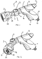
- Figures 1 to 5 show a hose gun comprising a gun body 1, a water outlet head 2, and in between these two hinge means 3.
- the hinge means 3 comprises a knuckle joint.
- the gun body 1 comprises a user grip portion 11 and a barrel portion 12.
- the user grip portion 11 joins with the barrel portion 12 part way along its length.
- the barrel portion 12 and user grip portion 11 are moulded together as one plastics component.
- a water inlet connector 13 is provided at the end of the grip portion 11 for connecting the hose gun to a hose (not shown).
- a water flow path is provided through the hose gun from the inlet connector 13 to the outlet head 2, as can be seen most clearly in Figure 5 .
- the gun body 1 carries a trigger 14 allowing the user to control flow of water through the gun.
- the trigger 14 operates a valve arrangement 15 (see Figure 5 ) such that when the trigger 14 is squeezed water is allowed to flow through the gun, whereas when the trigger 14 is released water flow through the gun is prevented.
- a lock button 16 is provided for locking the trigger 14 in an "on" position so that water can flow through the gun without the user continuing to squeeze the trigger 14.
- a flow restrictor 17 is provided which allows the user to control the rate of flow through the hose gun separately from operation of the trigger 14. That is to say the flow restrictor 17 limits the maximum flow rate through the gun which is achievable even when the trigger 14 is pulled to the fully on position.
- the water flow path then continues through the knuckle joint 3 to the water outlet head 2.
- a number of different water outlet features 21 to 24 are provided for providing different watering effects.
- the water outlet head 2 can be termed a feature head 2.
- One of these outlet features is a sprinkler feature 23.
- the sprinkler feature 23 is a static sprinkler feature which provides a relatively fine and diffuse water outlet effect which is suitable for sprinkler operation when the feature head 2 is appropriately orientated.
- a front portion 25 of the feature head is rotatable relative to a rear portion 26 to select the desired watering feature 21 to 24 for water outlet.
- the hose gun has a general water outlet axis which is generally perpendicular to the face of the outlet head in which the outlet features 21 to 24 are provided. This corresponds to the general or mean direction in which the water travels as it leaves the gun.
- the hinge means or knuckle joint 3 in the present embodiment between the hose gun body 1 and the outlet head 2.
- This allows the outlet head 2 to be moved from a forward watering position, as shown in Figure 1 , through intermediate positions, such as that shown in Figure 2 , to a sideways directed position as shown in Figure 3 .
- the hose gun When the outlet head 2 is in the sideways facing position, as shown in Figure 3 , the hose gun may be laid on its side on a surface S, as shown in Figure 4 , with the water outlet head 2 directed upwardly and the barrel portion 12 and grip portion 11 of the hose gun acting as a base supporting the gun. In this orientation, with the hose gun put into a locked "on" configuration, the hose gun may be used as a sprinkler. This is particularly effective if the sprinkler feature 23 is selected at the water outlet head 2.
- the user grip body portion 11 of the gun body 1 is at an angle to (i.e. not in line with) the barrel portion 12 of the gun, this leads to increased stability of the gun body 1 as a base. Further, because the grip body portion 11 meets the barrel portion 12 part way along its length, such that the barrel portion extends or projects in both directions away from the grip portion 11, again this tends to increase stability.
- parts of the knuckle joint 3 also tend to contact the ground with the gun in the orientation shown in Figure 4 , further lending stability. This is aided by the gun body 1 having a generally projection-free side surface on which the gun body can rest and having the knuckle joint/hinge means arranged so that it is generally flush with the side surface of the gun body when the feature head 2 is orientated in the sideways direction as shown in Figure 4 .
- the knuckle joint (hinge means) 3 comprises a first portion 31 which is fixedly mounted on the gun body 1, in particular sonic welded to the barrel 12 in the present embodiment, and a second portion 32 which is mounted to the feature head 2 and again in the present embodiment sonic welded thereto.
- the first and second portions 31, 32 of the knuckle joint are mounted together and arranged to rotate relative to one another around a pivot axis A to provide the hinging function as illustrated in Figures 1 to 4 .
- the first portion 31 includes a water inlet channel 33 and the second portion 32 includes a water outlet channel 34. These are in fluid communication with one another and remain in fluid communication with one another as the feature head 2 is moved around the pivot axis.
- the fluid communication is provided by an annular chamber 35 which is defined between the first and second portions 31 and 32.
- O-ring seals 36 and 37 are provided to give this sealed path through the knuckle joint 3.
- the knuckle joint 33 comprises indexing means 38, 39 for indexing movement of the feature head 2 around the pivot axis A relative to the gun body 1.
- the indexing means comprises a resiliently biased pin 38 carried in the second portion 32 of the knuckle joint 3 and a series of recesses 39 (only one of which can be seen in the drawings) provided in the first portion 31 of the knuckle joint.
- the pin 38 locates in respective ones of the recesses 39 and may ride out of a recess 39, as the user moves the feature head on towards another index position.
- this indexing provides some resistance to movement of the feature head 2 relative to the gun body 1 around the pivot axis A. This helps prevent movement of the feature head 2 away from a selected position and in particular tends to prevent any straightening out effect which might occur.
- One of the indexed positions corresponds to the forward water position, as shown in Figure 1 , where the feature head 2 is axially aligned with the gun body 1, in particular the barrel 12.
- the hose gun comprises two stop portions 4 which are provided to give an accurate stop position at the end of the range of movement permitted by the knuckle joint 3.
- the stop portions 4 are provided on the first and second portions 31, 32 of the knuckle joint 3 and can be seen apart in, for example, Figure 1 and contacting with one another in an operative stop position in Figures 3 and 4 .
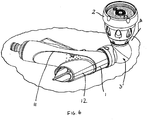
- FIG. 6 shows an alternative form of hose gun which is similar to that shown and described with reference to Figures 1 to 5 , but which includes a different form of hinge means.
- a ball joint hinge 3' is provided as the hinge means between the feature head 2 and the gun body 1.
- the alternative hose gun is shown in a sprinkler configuration with the feature head 2 facing in a sideways direction relative to the gun body 1.
- the pivot axis A of the ball joint hinge 3' is at a non-perpendicular angle to both the axis of the feature head 2 and the barrel portion 12 of the gun body 1.
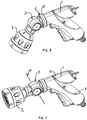
- FIGS 7 and 8 show another alternative hose gun. Again this has a gun body 1 and a feature head 2 separated by hinge means 3, which again is a knuckle joint 3.
- this hose gun has all the features of the hose gun described with reference to Figures 1 to 5 but includes additional pivot means.
- the knuckle joint 3 is fixed in relation to the gun body 1 such that it is held against rotation relative to the gun body 1.
- the first portion 31 of the knuckle joint 3 in the embodiment of Figure 1 is fixedly held against rotation (around its axis/the axis of the barrel 12) relative to the gun body 1.
- the hose gun of Figures 7 and 8 includes latching pivot means 5 between the gun body 1 and the knuckle joint 3.
- the latching pivot means 5 allow the hinge means 3 and feature head 2 to be rotated about their own axis from an orientation such as that shown in Figure 1 to an orientation as shown in Figure 7 .
- the pivot axis A of the hinge means 3 can be rotated relative to the gun body 1. It will be noted that in an orientation such as shown in Figure 1 the pivot axis of the hinge means is in a plane which is also occupied by the barrel portion 12 and grip portion 11 of the gun body, whereas in the orientation shown in Figure 7 this pivot axis A is particular thereto.
- Such a latchable pivot means 5 may also be provided in a hose gun with a ball joint hinge 3' of the type shown in Figure 6 . Then again rotation of the hinge means 3 and feature head 2 about their own axis allows rotation of the pivot axis about which the hinge operates.
- the latching pivot means 5 allows rotation of the hinge means 3 about its axis (so rotating the pivot axis of the hinge means) by 90 degrees between the orientation shown in Figure 7 and one such as shown in Figure 1 . Further the latching pivot means 5 latches or locks the hinge means 3 in whichever one of these two orientations is selected.
- the hinge means 3 is put in the orientation shown in Figure 7 , twisting of the feature head 2 will not cause the hinge means 3 to rotate relative to the gun body 1 as the latch in the latching pivot means 5 will resist this.
- twisting of the feature head 2 will not cause the hinge 3 to rotate relative to the gun body 1 as again the latching pivot means 5 will serve to prevent this.
- the latchable pivot means 5 includes a latching collar 51 which is moveable relative to the gun body 1 away from the remainder of the latching pivot means 5 to release the latch.
- a user desires to move the hinge from the orientation shown in Figure 7 towards an orientation such as that shown in Figure 1 (or vice versa)
- the user moves the collar 51 away from the hinge 3 to release the pivot means 5.
- the feature head 2 and hinge 3 may be rotated around their axis relative to the gun body 1.
- the latching collar 51 may be released to latch the hinge 3 in position.
- the latchable means 5 provides the ability to rotate the hinge means 3 by 90 degrees around its own axis and correspondingly move the pivot axis of the hinge means 3 through 90 degrees.
- the latching pivot means 5 may allow latching of the hinge means 3 in a selected one of at least two available latching orientations.
Landscapes
- Engineering & Computer Science (AREA)
- Water Supply & Treatment (AREA)
- Life Sciences & Earth Sciences (AREA)
- Environmental Sciences (AREA)
- Nozzles (AREA)
- Details Or Accessories Of Spraying Plant Or Apparatus (AREA)
Claims (15)
- Eine Schlauchpistole, die einen Pistolenkörper (1) und einen Wasserauslasskopf (2) zum Ausstoßen von Wasser aus der Pistole umfasst, wobei der Pistolenkörper (1) einen Benutzergriff-Körperabschnitt (11) und einen zweiten Körperabschnitt (12) aufweist, der in einem Winkel zu dem Benutzergriffabschnitt (11) steht, wobei Verbindungsmittel (3) zwischen dem Wasserauslasskopf (2) und dem Pistolenkörper (1) bereitgestellt sind, die es dem Wasserauslasskopf (2) ermöglichen, relativ zum Pistolenkörper (1) zwischen einer nach vorne gerichteten Bewässerungsposition und einer Sprinklerposition, in der die Schlauchpistole auf einer Oberfläche positionierbar ist, bewegt zu werden, wobei der Benutzergriff-Körperabschnitt (11) und der zweite Körperabschnitt (12) als eine Basis wirken und der Wasserauslasskopf (2) nach oben gerichtet ist, wobei der Wasserauslasskopf (2) eine Wasserauslassachse aufweist und wenn sich der Auslasskopf (2) in der nach vorne gerichteten Bewässerungsposition befindet, die Wasserauslassachse (2) auf oder parallel zu einer Ebene gerichtet ist, die der Griffkörperabschnitt (11) und der zweite Körperabschnitt (12) einnehmen, während die Wasserauslassachse von dieser Ebene weggerichtet ist, wenn sich der Wasserauslasskopf (2) in der Sprinklerposition befindet.
- Schlauchpistole nach Anspruch 1, wobei das Verbindungsmittel (3) ein Drehgelenkmittel ist.
- Schlauchpistole nach Anspruch 2, wobei eine Schwenkachse des Drehgelenkmittels (3) auf oder parallel zu einer Ebene liegt, die der Benutzergriff-Körperabschnitt (11) und der zweite Körperabschnitt (12) einnehmen, zumindest wenn die Schlauchpistole so konfiguriert ist, dass sie eine Bewegung des Wasserauslasskopfes (2) in die Sprinklerposition ermöglicht.
- Schlauchpistole nach einem der vorangehenden Ansprüche, wobei das Verbindungsmittel (3) einen ersten und einen zweiten Abschnitt (31, 32) umfasst, die relativ zueinander beweglich sind, wobei der erste Abschnitt (31) am Pistolenkörper (1) und der zweite Abschnitt (32) am Wasserauslasskopf (2) montiert sind.
- Schlauchpistole nach Anspruch 4, wobei der erste Abschnitt (31) des Verbindungsmittels (3) relativ zum Pistolenkörper (1) drehfest gehalten wird.
- Schlauchpistole nach Anspruch 5, wobei der erste Abschnitt (31) des Verbindungsmittels (3) relativ zum Pistolenkörper (1) drehfest gehalten wird.
- Schlauchpistole nach Anspruch 5, wobei der erste Abschnitt des Verbindungsmittels (3) relativ zum Pistolenkörper (1) lösbar verriegelt ist.
- Schlauchpistole nach Anspruch 7, wobei die Verbindungsmittel (3) Drehgelenkmittel sind und die Schlauchpistole Schwenkmittel (5) umfasst, die eine Drehung des ersten Abschnitts (31) des Drehgelenkmittels um seine eigene Achse herum relativ zum Pistolenkörper (1) ermöglichen, um eine Schwenkachse (A) des Drehgelenkmittels (3) relativ zum Pistolenkörper (1) zu drehen, wobei die Schwenkmittel (5) lösbare Verriegelungsmittel (51) umfasst, die zum Verriegeln des ersten Abschnitts (31) des Drehgelenkmittels (3) in mindestens einer ausgewählten Ausrichtung relativ zum Pistolenkörper (1) angeordnet sind und so angeordnet sind, dass sie eine Drehung des ersten Abschnitts (31) der Drehgelenkmittels (3) relativ zum Pistolenkörper (1) ermöglichen, wenn die Verriegelungsmittel (51) gelöst sind.
- Schlauchpistole nach Anspruch 8, wobei die Verriegelungsmittel (51) so angeordnet sind, dass sie den ersten Abschnitt (31) des Drehgelenkmittels (3) in einer ersten Ausrichtung relativ zum Pistolenkörper (1) verriegelen und den ersten Abschnitt (31) der Drehgelenkmittel (3) in einer zweiten Ausrichtung relativ zum Pistolenkörper (1) verriegeln, wobei die beiden Ausrichtungen in einem Winkel voneinander getrennt sind.
- Schlauchpistole nach Anspruch 8 oder 9, wobei die Verriegelungsmittel (51) so angeordnet sind, dass eine Bewegung, die sich von der des Drehens des Drehgelenkmittels um seine eigene Achse relativ zum Pistolenkörper unterscheidet, erforderlich ist, um die Verriegelungsmittel (51) zu lösen.
- Schlauchpistole nach einem der Ansprüche 8 bis 10, wobei die Schlauchpistole eine erste Konfiguration aufweist, bei der das Drehgelenkmittel (3) in einer Ausrichtung verriegelt ist, die eine Links-/Rechts-Bewegung des Wasserauslasskopfes (2) relativ zum Pistolenkörper (1) ermöglicht, und eine zweite Konfiguration, bei der das Drehgelenkmittel (3) in einer Ausrichtung verriegelt ist, die eine Aufwärts-/Abwärts-Bewegung des Wasserauslasskopfes (2) relativ zum Pistolenkörper (1) ermöglicht.
- Schlauchpistole nach einem der vorangehenden Ansprüche, wobei das Drehgelenkmittel (3) eine Schaltanordnung (38, 39), die einen elastisch montierten Stift umfasst (38), der auf einem der ersten und zweiten Abschnitte (31, 32) des Drehgelenkmittels (3) bereitgestellt ist, und eine Reihe von Stiftaufnahmestellen (39) umfasst, die auf dem anderen der ersten und zweiten Abschnitte (32, 31) des Drehgelenkmittels (3) bereitgestellt sind, so dass der Wasserauslasskopf (2) durch eine Reihe von Schaltstellungen relativ zum Pistolenkörper (1) bewegt werden kann, wobei jede Schaltstellung so gewählt ist, dass der Stift (38) in einer entsprechenden der Aufnahmestellen (39) aufgenommen wird.
- Schlauchpistole nach Anspruch 12, wobei eine ungerade Anzahl von Aufnahmestellen (39) bereitgestellt ist, von denen eine zentrale Stelle einer zentralen Position des Wasserauslasskopfs (2) relativ zum Pistolenkörper (1) entspricht.
- Schlauchpistole nach einem der vorangehenden Ansprüche, wobei sich der zweite Körperabschnitt (12) von beiden Seiten eines Bereichs weg erstreckt, in dem der Griffkörperabschnitt (11) auf den zweiten Körperabschnitt (12) trifft.
- Schlauchpistole nach einem der vorangehenden Ansprüche, wobei der zweite Körperabschnitt (12) des Pistolenkörpers (1) ein Zylinderabschnitt ist, wobei die Verbindungsmittel (3) an dem Zylinderabschnitt (12) und der Griffkörperabschnitt (11) an dem Zylinderabschnitt (12) montiert sind.
Priority Applications (2)
| Application Number | Priority Date | Filing Date | Title |
|---|---|---|---|
| EP19219918.0A EP3659712A1 (de) | 2013-09-30 | 2014-09-30 | Schlauchpistole |
| PL14781615T PL3052247T3 (pl) | 2013-09-30 | 2014-09-30 | Pistolet do węży |
Applications Claiming Priority (2)
| Application Number | Priority Date | Filing Date | Title |
|---|---|---|---|
| GB1317345.5A GB2518692B (en) | 2013-09-30 | 2013-09-30 | Hose guns |
| PCT/GB2014/000386 WO2015044633A1 (en) | 2013-09-30 | 2014-09-30 | Hose guns |
Related Child Applications (2)
| Application Number | Title | Priority Date | Filing Date |
|---|---|---|---|
| EP19219918.0A Division-Into EP3659712A1 (de) | 2013-09-30 | 2014-09-30 | Schlauchpistole |
| EP19219918.0A Division EP3659712A1 (de) | 2013-09-30 | 2014-09-30 | Schlauchpistole |
Publications (2)
| Publication Number | Publication Date |
|---|---|
| EP3052247A1 EP3052247A1 (de) | 2016-08-10 |
| EP3052247B1 true EP3052247B1 (de) | 2020-03-25 |
Family
ID=49585108
Family Applications (2)
| Application Number | Title | Priority Date | Filing Date |
|---|---|---|---|
| EP19219918.0A Ceased EP3659712A1 (de) | 2013-09-30 | 2014-09-30 | Schlauchpistole |
| EP14781615.1A Active EP3052247B1 (de) | 2013-09-30 | 2014-09-30 | Schlauchpistolen |
Family Applications Before (1)
| Application Number | Title | Priority Date | Filing Date |
|---|---|---|---|
| EP19219918.0A Ceased EP3659712A1 (de) | 2013-09-30 | 2014-09-30 | Schlauchpistole |
Country Status (8)
| Country | Link |
|---|---|
| US (1) | US10239074B2 (de) |
| EP (2) | EP3659712A1 (de) |
| CN (2) | CN105813764B (de) |
| AU (1) | AU2014326395B2 (de) |
| GB (1) | GB2518692B (de) |
| PL (1) | PL3052247T3 (de) |
| RU (1) | RU2665417C2 (de) |
| WO (1) | WO2015044633A1 (de) |
Families Citing this family (12)
| Publication number | Priority date | Publication date | Assignee | Title |
|---|---|---|---|---|
| TWM517021U (zh) * | 2015-08-20 | 2016-02-11 | 懿澤企業有限公司 | 多功能噴水結構 |
| USD792947S1 (en) * | 2016-05-13 | 2017-07-25 | Ruey Ryh Enterprise Co., Ltd. | Sprinkler gun |
| USD792944S1 (en) * | 2016-05-17 | 2017-07-25 | Yuan Mei Corp. | Sprinkler gun |
| USD792945S1 (en) * | 2016-05-17 | 2017-07-25 | Yuan Mei Corp. | Sprinkler gun |
| CN109013137A (zh) * | 2018-09-27 | 2018-12-18 | 市下控股有限公司 | 喷枪手柄的喷头旋转定位机构 |
| IT201900002237A1 (it) * | 2019-02-15 | 2020-08-15 | Promega S R L | Pistola a spruzzo con elemento di regolazione |
| USD919752S1 (en) * | 2019-09-17 | 2021-05-18 | Shin Tai Spurt Water Of The Garden Tools Co., Ltd. | Gardening spray gun |
| USD926932S1 (en) * | 2019-09-19 | 2021-08-03 | Shin Tai Spurt Water Of The Garden Tools Co., Ltd. | Gardening water spray gun |
| USD931413S1 (en) * | 2019-11-14 | 2021-09-21 | Shin Tai Spurt Water Of The Garden Tools Co., Ltd. | Gardening water spray gun |
| US20230302481A1 (en) * | 2022-03-28 | 2023-09-28 | Span & Company LLC | Adjustable high reach sprinkler head |
| US20250153198A1 (en) * | 2023-11-13 | 2025-05-15 | Shin Tai Spurt Water Of The Garden Tools Co., Ltd. | Garden Hose Nozzle |
| US20250229285A1 (en) * | 2024-01-15 | 2025-07-17 | Shin Tai Spurt Water Of The Garden Tools Co., Ltd. | Gardening water spray gun with replaceable sprinkler head |
Family Cites Families (26)
| Publication number | Priority date | Publication date | Assignee | Title |
|---|---|---|---|---|
| US1125642A (en) * | 1913-09-02 | 1915-01-19 | Arthur H Blanchard | Adjustable coupling. |
| DE2304738C3 (de) * | 1973-01-31 | 1978-03-30 | Oberdorfer, Guido, 7919 Bellenberg | Handgerät zum Reinigen mittels Flüssigkeitsstrahlen |
| JPS5652629B2 (de) * | 1973-10-11 | 1981-12-14 | ||
| SU925408A1 (ru) * | 1980-10-02 | 1982-05-07 | Предприятие П/Я А-1080 | Распылительный пистолет |
| SU1014590A1 (ru) * | 1981-07-29 | 1983-04-30 | Предприятие П/Я А-1080 | Установка дл нанесени покрыти |
| CN2124770U (zh) * | 1992-05-14 | 1992-12-16 | 范德美 | 一种喷头 |
| US6926213B2 (en) * | 1997-08-18 | 2005-08-09 | Charles Coles | Power washer wand |
| US6042029A (en) * | 1998-03-27 | 2000-03-28 | Massey; Marvin E. | Dual-outlet fire service line connector |
| US6568610B1 (en) * | 2000-08-12 | 2003-05-27 | K. C. Ericksen | Flexible lawn and garden spray wand |
| US6554209B2 (en) * | 2000-12-06 | 2003-04-29 | Simeon Djordjevic | Combination hose nozzle and lawn sprinkler |
| US6257505B1 (en) * | 2000-12-13 | 2001-07-10 | King-Yuan Wang | Sprinkling head structure of sprinkling gun |
| US6508415B2 (en) * | 2001-05-16 | 2003-01-21 | Wang Tzu-Meng | Spray head with a pivot nozzle |
| TW543509U (en) * | 2002-04-29 | 2003-07-21 | Wen-Li Guo | Improved structure for water sprinkle-nozzle |
| DE20307530U1 (de) * | 2003-05-14 | 2003-07-24 | Wang, Hsin-Fa, Lou Kang, Changhua | Gartensprinkler |
| GB0319698D0 (en) | 2003-08-21 | 2003-09-24 | Hozelock Ltd | Hose guns |
| US20120225916A1 (en) * | 2003-12-29 | 2012-09-06 | Mcdevitt Jason P | Compositions and Methods to Improve Treatment of Medical Conditions Using D-Cycloserine |
| DE102004058867B4 (de) * | 2004-01-15 | 2022-09-01 | Suttner Gmbh | Sprühlanze für eine Hochdruckreinigungsvorrichtung und Gelenk für eine Düse einer Hochdruckreinigungsvorrichtung |
| WO2006019231A1 (en) * | 2004-08-19 | 2006-02-23 | Duck-Shin Lee | Multi-purpose water sprayer in horticulture |
| KR100588629B1 (ko) * | 2004-08-19 | 2006-06-14 | 하유길 | 원예용 다목적 물 분사기 |
| TWM288203U (en) * | 2005-04-25 | 2006-03-01 | Yi-Shuen Shr | Water sprayer allowing varying water spraying configuration in one-hand |
| DE102008000396A1 (de) * | 2008-02-25 | 2009-08-27 | Robert Bosch Gmbh | Spritzpistole mit einer Verlängerungseinrichtung zur Verlängerung des Handgriffs der Spritzpistole |
| CN201287095Y (zh) * | 2008-09-18 | 2009-08-12 | 九豪精密陶瓷(昆山)有限公司 | 气压枪 |
| CA2784923C (en) * | 2009-12-17 | 2019-07-09 | Partners In Innovation Limited, Llc | Garden watering device |
| US9724708B2 (en) * | 2009-12-17 | 2017-08-08 | Partners In Innovation Ltd. | Garden watering device |
| CN201618646U (zh) * | 2010-01-29 | 2010-11-03 | 上海欧菲滤清器有限公司 | 一种连接于生产流水线的气动喷枪 |
| CN202387611U (zh) * | 2011-12-23 | 2012-08-22 | 刘子辉 | 万向泡沫枪 |
-
2013
- 2013-09-30 GB GB1317345.5A patent/GB2518692B/en active Active
-
2014
- 2014-09-30 US US15/025,973 patent/US10239074B2/en not_active Expired - Fee Related
- 2014-09-30 WO PCT/GB2014/000386 patent/WO2015044633A1/en not_active Ceased
- 2014-09-30 AU AU2014326395A patent/AU2014326395B2/en not_active Ceased
- 2014-09-30 RU RU2016114095A patent/RU2665417C2/ru active
- 2014-09-30 EP EP19219918.0A patent/EP3659712A1/de not_active Ceased
- 2014-09-30 CN CN201480053781.9A patent/CN105813764B/zh active Active
- 2014-09-30 CN CN201910585132.8A patent/CN110252537B/zh active Active
- 2014-09-30 PL PL14781615T patent/PL3052247T3/pl unknown
- 2014-09-30 EP EP14781615.1A patent/EP3052247B1/de active Active
Non-Patent Citations (1)
| Title |
|---|
| None * |
Also Published As
| Publication number | Publication date |
|---|---|
| EP3659712A1 (de) | 2020-06-03 |
| US20160243568A1 (en) | 2016-08-25 |
| CN105813764B (zh) | 2019-07-16 |
| RU2665417C2 (ru) | 2018-08-29 |
| GB201317345D0 (en) | 2013-11-13 |
| AU2014326395A1 (en) | 2016-04-21 |
| EP3052247A1 (de) | 2016-08-10 |
| US10239074B2 (en) | 2019-03-26 |
| AU2014326395B2 (en) | 2018-10-25 |
| PL3052247T3 (pl) | 2020-09-07 |
| RU2016114095A3 (de) | 2018-03-22 |
| CN110252537B (zh) | 2021-09-07 |
| WO2015044633A1 (en) | 2015-04-02 |
| GB2518692A (en) | 2015-04-01 |
| RU2016114095A (ru) | 2017-11-13 |
| CN105813764A (zh) | 2016-07-27 |
| CN110252537A (zh) | 2019-09-20 |
| GB2518692B (en) | 2019-12-18 |
Similar Documents
| Publication | Publication Date | Title |
|---|---|---|
| US10239074B2 (en) | Hose guns | |
| EP2427276B1 (de) | Sprühgerät mit fernbetätigter drehbarer und selektiv blockierbarer düse | |
| US10973219B2 (en) | Dual nozzle sprayer | |
| US9757742B2 (en) | Showerhead assembly with primary showerhead and orbiting showerhead | |
| US11278920B2 (en) | Showerhead assembly with dual nozzle mount | |
| US20140084083A1 (en) | Fluid-Dispensing Nozzle | |
| US6644625B1 (en) | Pistol grip hose nozzle with proportional flow control | |
| JP6328444B2 (ja) | 消防用ノズル | |
| CN108014935B (zh) | 一种压力线性调节组合喷嘴及高压清洗设备 | |
| CN103549902A (zh) | 侧喷淋浴系统 | |
| GB2575599A (en) | Hose guns | |
| CN219630506U (zh) | 一种多功能消防水枪 | |
| JP3228957U (ja) | 散水ノズル用ヘッド部及び散水ノズル | |
| KR20230062293A (ko) | 분사 약대의 약액 공급 구조 | |
| CN109013137A (zh) | 喷枪手柄的喷头旋转定位机构 | |
| CN202621327U (zh) | 一种三合一组合喷头 | |
| KR100611944B1 (ko) | 농약분사대의 호스 꼬임 방지구조 | |
| CN102679059B (zh) | 一种水管接头 | |
| CN206763191U (zh) | 能够手持与定置使用的水涡轮双用喷水枪 | |
| WO2019109396A1 (zh) | 一种多种出水方式的玩具水枪喷头及玩具水枪 | |
| TWM580460U (zh) | Sprinkler | |
| TWM459912U (zh) | 指控式園藝噴水槍 |
Legal Events
| Date | Code | Title | Description |
|---|---|---|---|
| PUAI | Public reference made under article 153(3) epc to a published international application that has entered the european phase |
Free format text: ORIGINAL CODE: 0009012 |
|
| 17P | Request for examination filed |
Effective date: 20160324 |
|
| AK | Designated contracting states |
Kind code of ref document: A1 Designated state(s): AL AT BE BG CH CY CZ DE DK EE ES FI FR GB GR HR HU IE IS IT LI LT LU LV MC MK MT NL NO PL PT RO RS SE SI SK SM TR |
|
| AX | Request for extension of the european patent |
Extension state: BA ME |
|
| DAX | Request for extension of the european patent (deleted) | ||
| RIC1 | Information provided on ipc code assigned before grant |
Ipc: B05B 9/01 20060101AFI20190812BHEP Ipc: B05B 15/625 20180101ALI20190812BHEP Ipc: B05B 15/652 20180101ALI20190812BHEP |
|
| GRAP | Despatch of communication of intention to grant a patent |
Free format text: ORIGINAL CODE: EPIDOSNIGR1 |
|
| STAA | Information on the status of an ep patent application or granted ep patent |
Free format text: STATUS: GRANT OF PATENT IS INTENDED |
|
| INTG | Intention to grant announced |
Effective date: 20191009 |
|
| GRAS | Grant fee paid |
Free format text: ORIGINAL CODE: EPIDOSNIGR3 |
|
| GRAA | (expected) grant |
Free format text: ORIGINAL CODE: 0009210 |
|
| STAA | Information on the status of an ep patent application or granted ep patent |
Free format text: STATUS: THE PATENT HAS BEEN GRANTED |
|
| RBV | Designated contracting states (corrected) |
Designated state(s): AL AT BE BG CH CY CZ DE DK EE ES FI FR GR HR HU IE IS IT LI LT LU LV MC MK MT NL NO PL PT RO RS SE SI SK SM TR |
|
| AK | Designated contracting states |
Kind code of ref document: B1 Designated state(s): AL AT BE BG CH CY CZ DE DK EE ES FI FR GR HR HU IE IS IT LI LT LU LV MC MK MT NL NO PL PT RO RS SE SI SK SM TR |
|
| REG | Reference to a national code |
Ref country code: AT Ref legal event code: REF Ref document number: 1247977 Country of ref document: AT Kind code of ref document: T Effective date: 20200415 Ref country code: IE Ref legal event code: FG4D |
|
| REG | Reference to a national code |
Ref country code: DE Ref legal event code: R096 Ref document number: 602014062857 Country of ref document: DE |
|
| PG25 | Lapsed in a contracting state [announced via postgrant information from national office to epo] |
Ref country code: NO Free format text: LAPSE BECAUSE OF FAILURE TO SUBMIT A TRANSLATION OF THE DESCRIPTION OR TO PAY THE FEE WITHIN THE PRESCRIBED TIME-LIMIT Effective date: 20200625 Ref country code: RS Free format text: LAPSE BECAUSE OF FAILURE TO SUBMIT A TRANSLATION OF THE DESCRIPTION OR TO PAY THE FEE WITHIN THE PRESCRIBED TIME-LIMIT Effective date: 20200325 Ref country code: FI Free format text: LAPSE BECAUSE OF FAILURE TO SUBMIT A TRANSLATION OF THE DESCRIPTION OR TO PAY THE FEE WITHIN THE PRESCRIBED TIME-LIMIT Effective date: 20200325 |
|
| PG25 | Lapsed in a contracting state [announced via postgrant information from national office to epo] |
Ref country code: BG Free format text: LAPSE BECAUSE OF FAILURE TO SUBMIT A TRANSLATION OF THE DESCRIPTION OR TO PAY THE FEE WITHIN THE PRESCRIBED TIME-LIMIT Effective date: 20200625 Ref country code: SE Free format text: LAPSE BECAUSE OF FAILURE TO SUBMIT A TRANSLATION OF THE DESCRIPTION OR TO PAY THE FEE WITHIN THE PRESCRIBED TIME-LIMIT Effective date: 20200325 Ref country code: LV Free format text: LAPSE BECAUSE OF FAILURE TO SUBMIT A TRANSLATION OF THE DESCRIPTION OR TO PAY THE FEE WITHIN THE PRESCRIBED TIME-LIMIT Effective date: 20200325 Ref country code: HR Free format text: LAPSE BECAUSE OF FAILURE TO SUBMIT A TRANSLATION OF THE DESCRIPTION OR TO PAY THE FEE WITHIN THE PRESCRIBED TIME-LIMIT Effective date: 20200325 |
|
| REG | Reference to a national code |
Ref country code: NL Ref legal event code: MP Effective date: 20200325 |
|
| REG | Reference to a national code |
Ref country code: LT Ref legal event code: MG4D |
|
| REG | Reference to a national code |
Ref country code: GR Ref legal event code: EP Ref document number: 20200401693 Country of ref document: GR Effective date: 20200916 |
|
| PG25 | Lapsed in a contracting state [announced via postgrant information from national office to epo] |
Ref country code: NL Free format text: LAPSE BECAUSE OF FAILURE TO SUBMIT A TRANSLATION OF THE DESCRIPTION OR TO PAY THE FEE WITHIN THE PRESCRIBED TIME-LIMIT Effective date: 20200325 |
|
| PG25 | Lapsed in a contracting state [announced via postgrant information from national office to epo] |
Ref country code: PT Free format text: LAPSE BECAUSE OF FAILURE TO SUBMIT A TRANSLATION OF THE DESCRIPTION OR TO PAY THE FEE WITHIN THE PRESCRIBED TIME-LIMIT Effective date: 20200818 Ref country code: EE Free format text: LAPSE BECAUSE OF FAILURE TO SUBMIT A TRANSLATION OF THE DESCRIPTION OR TO PAY THE FEE WITHIN THE PRESCRIBED TIME-LIMIT Effective date: 20200325 Ref country code: CZ Free format text: LAPSE BECAUSE OF FAILURE TO SUBMIT A TRANSLATION OF THE DESCRIPTION OR TO PAY THE FEE WITHIN THE PRESCRIBED TIME-LIMIT Effective date: 20200325 Ref country code: RO Free format text: LAPSE BECAUSE OF FAILURE TO SUBMIT A TRANSLATION OF THE DESCRIPTION OR TO PAY THE FEE WITHIN THE PRESCRIBED TIME-LIMIT Effective date: 20200325 Ref country code: SM Free format text: LAPSE BECAUSE OF FAILURE TO SUBMIT A TRANSLATION OF THE DESCRIPTION OR TO PAY THE FEE WITHIN THE PRESCRIBED TIME-LIMIT Effective date: 20200325 Ref country code: SK Free format text: LAPSE BECAUSE OF FAILURE TO SUBMIT A TRANSLATION OF THE DESCRIPTION OR TO PAY THE FEE WITHIN THE PRESCRIBED TIME-LIMIT Effective date: 20200325 Ref country code: LT Free format text: LAPSE BECAUSE OF FAILURE TO SUBMIT A TRANSLATION OF THE DESCRIPTION OR TO PAY THE FEE WITHIN THE PRESCRIBED TIME-LIMIT Effective date: 20200325 Ref country code: IS Free format text: LAPSE BECAUSE OF FAILURE TO SUBMIT A TRANSLATION OF THE DESCRIPTION OR TO PAY THE FEE WITHIN THE PRESCRIBED TIME-LIMIT Effective date: 20200725 |
|
| PGFP | Annual fee paid to national office [announced via postgrant information from national office to epo] |
Ref country code: GR Payment date: 20200826 Year of fee payment: 7 |
|
| REG | Reference to a national code |
Ref country code: AT Ref legal event code: MK05 Ref document number: 1247977 Country of ref document: AT Kind code of ref document: T Effective date: 20200325 |
|
| REG | Reference to a national code |
Ref country code: DE Ref legal event code: R097 Ref document number: 602014062857 Country of ref document: DE |
|
| PG25 | Lapsed in a contracting state [announced via postgrant information from national office to epo] |
Ref country code: AT Free format text: LAPSE BECAUSE OF FAILURE TO SUBMIT A TRANSLATION OF THE DESCRIPTION OR TO PAY THE FEE WITHIN THE PRESCRIBED TIME-LIMIT Effective date: 20200325 Ref country code: ES Free format text: LAPSE BECAUSE OF FAILURE TO SUBMIT A TRANSLATION OF THE DESCRIPTION OR TO PAY THE FEE WITHIN THE PRESCRIBED TIME-LIMIT Effective date: 20200325 Ref country code: DK Free format text: LAPSE BECAUSE OF FAILURE TO SUBMIT A TRANSLATION OF THE DESCRIPTION OR TO PAY THE FEE WITHIN THE PRESCRIBED TIME-LIMIT Effective date: 20200325 |
|
| PLBE | No opposition filed within time limit |
Free format text: ORIGINAL CODE: 0009261 |
|
| STAA | Information on the status of an ep patent application or granted ep patent |
Free format text: STATUS: NO OPPOSITION FILED WITHIN TIME LIMIT |
|
| 26N | No opposition filed |
Effective date: 20210112 |
|
| PG25 | Lapsed in a contracting state [announced via postgrant information from national office to epo] |
Ref country code: MC Free format text: LAPSE BECAUSE OF FAILURE TO SUBMIT A TRANSLATION OF THE DESCRIPTION OR TO PAY THE FEE WITHIN THE PRESCRIBED TIME-LIMIT Effective date: 20200325 |
|
| REG | Reference to a national code |
Ref country code: CH Ref legal event code: PL |
|
| PG25 | Lapsed in a contracting state [announced via postgrant information from national office to epo] |
Ref country code: SI Free format text: LAPSE BECAUSE OF FAILURE TO SUBMIT A TRANSLATION OF THE DESCRIPTION OR TO PAY THE FEE WITHIN THE PRESCRIBED TIME-LIMIT Effective date: 20200325 |
|
| REG | Reference to a national code |
Ref country code: BE Ref legal event code: MM Effective date: 20200930 |
|
| PG25 | Lapsed in a contracting state [announced via postgrant information from national office to epo] |
Ref country code: LU Free format text: LAPSE BECAUSE OF NON-PAYMENT OF DUE FEES Effective date: 20200930 |
|
| PG25 | Lapsed in a contracting state [announced via postgrant information from national office to epo] |
Ref country code: IE Free format text: LAPSE BECAUSE OF NON-PAYMENT OF DUE FEES Effective date: 20200930 Ref country code: LI Free format text: LAPSE BECAUSE OF NON-PAYMENT OF DUE FEES Effective date: 20200930 Ref country code: BE Free format text: LAPSE BECAUSE OF NON-PAYMENT OF DUE FEES Effective date: 20200930 Ref country code: CH Free format text: LAPSE BECAUSE OF NON-PAYMENT OF DUE FEES Effective date: 20200930 |
|
| PG25 | Lapsed in a contracting state [announced via postgrant information from national office to epo] |
Ref country code: TR Free format text: LAPSE BECAUSE OF FAILURE TO SUBMIT A TRANSLATION OF THE DESCRIPTION OR TO PAY THE FEE WITHIN THE PRESCRIBED TIME-LIMIT Effective date: 20200325 Ref country code: MT Free format text: LAPSE BECAUSE OF FAILURE TO SUBMIT A TRANSLATION OF THE DESCRIPTION OR TO PAY THE FEE WITHIN THE PRESCRIBED TIME-LIMIT Effective date: 20200325 Ref country code: CY Free format text: LAPSE BECAUSE OF FAILURE TO SUBMIT A TRANSLATION OF THE DESCRIPTION OR TO PAY THE FEE WITHIN THE PRESCRIBED TIME-LIMIT Effective date: 20200325 |
|
| PG25 | Lapsed in a contracting state [announced via postgrant information from national office to epo] |
Ref country code: MK Free format text: LAPSE BECAUSE OF FAILURE TO SUBMIT A TRANSLATION OF THE DESCRIPTION OR TO PAY THE FEE WITHIN THE PRESCRIBED TIME-LIMIT Effective date: 20200325 Ref country code: AL Free format text: LAPSE BECAUSE OF FAILURE TO SUBMIT A TRANSLATION OF THE DESCRIPTION OR TO PAY THE FEE WITHIN THE PRESCRIBED TIME-LIMIT Effective date: 20200325 |
|
| PG25 | Lapsed in a contracting state [announced via postgrant information from national office to epo] |
Ref country code: GR Free format text: LAPSE BECAUSE OF NON-PAYMENT OF DUE FEES Effective date: 20220407 |
|
| PGFP | Annual fee paid to national office [announced via postgrant information from national office to epo] |
Ref country code: DE Payment date: 20250916 Year of fee payment: 12 |
|
| PGFP | Annual fee paid to national office [announced via postgrant information from national office to epo] |
Ref country code: PL Payment date: 20250825 Year of fee payment: 12 Ref country code: IT Payment date: 20250909 Year of fee payment: 12 |
|
| PGFP | Annual fee paid to national office [announced via postgrant information from national office to epo] |
Ref country code: FR Payment date: 20250929 Year of fee payment: 12 |