EP3051149B1 - Actionneur d'atterrisseur d'aéronef comprenant un système de commande comportant une tige de commande - Google Patents
Actionneur d'atterrisseur d'aéronef comprenant un système de commande comportant une tige de commande Download PDFInfo
- Publication number
- EP3051149B1 EP3051149B1 EP16152489.7A EP16152489A EP3051149B1 EP 3051149 B1 EP3051149 B1 EP 3051149B1 EP 16152489 A EP16152489 A EP 16152489A EP 3051149 B1 EP3051149 B1 EP 3051149B1
- Authority
- EP
- European Patent Office
- Prior art keywords
- zone
- guide piece
- ball pivot
- bore
- aircraft landing
- Prior art date
- Legal status (The legal status is an assumption and is not a legal conclusion. Google has not performed a legal analysis and makes no representation as to the accuracy of the status listed.)
- Active
Links
- 238000007789 sealing Methods 0.000 claims description 17
- 239000002184 metal Substances 0.000 claims description 9
- 239000012530 fluid Substances 0.000 claims description 7
- 238000000605 extraction Methods 0.000 description 6
- 238000012423 maintenance Methods 0.000 description 3
- 238000004519 manufacturing process Methods 0.000 description 3
- 238000000034 method Methods 0.000 description 3
- 240000008042 Zea mays Species 0.000 description 2
- 230000007547 defect Effects 0.000 description 2
- 238000001514 detection method Methods 0.000 description 2
- 238000006073 displacement reaction Methods 0.000 description 2
- 230000006978 adaptation Effects 0.000 description 1
- 230000000712 assembly Effects 0.000 description 1
- 238000000429 assembly Methods 0.000 description 1
- 230000000295 complement effect Effects 0.000 description 1
- 238000003754 machining Methods 0.000 description 1
- 230000002093 peripheral effect Effects 0.000 description 1
- 230000002035 prolonged effect Effects 0.000 description 1
- 238000009419 refurbishment Methods 0.000 description 1
- 239000007787 solid Substances 0.000 description 1
Images
Classifications
-
- F—MECHANICAL ENGINEERING; LIGHTING; HEATING; WEAPONS; BLASTING
- F15—FLUID-PRESSURE ACTUATORS; HYDRAULICS OR PNEUMATICS IN GENERAL
- F15B—SYSTEMS ACTING BY MEANS OF FLUIDS IN GENERAL; FLUID-PRESSURE ACTUATORS, e.g. SERVOMOTORS; DETAILS OF FLUID-PRESSURE SYSTEMS, NOT OTHERWISE PROVIDED FOR
- F15B15/00—Fluid-actuated devices for displacing a member from one position to another; Gearing associated therewith
- F15B15/20—Other details, e.g. assembly with regulating devices
- F15B15/28—Means for indicating the position, e.g. end of stroke
- F15B15/2807—Position switches, i.e. means for sensing of discrete positions only, e.g. limit switches
-
- B—PERFORMING OPERATIONS; TRANSPORTING
- B64—AIRCRAFT; AVIATION; COSMONAUTICS
- B64C—AEROPLANES; HELICOPTERS
- B64C25/00—Alighting gear
- B64C25/02—Undercarriages
- B64C25/08—Undercarriages non-fixed, e.g. jettisonable
- B64C25/10—Undercarriages non-fixed, e.g. jettisonable retractable, foldable, or the like
- B64C25/18—Operating mechanisms
- B64C25/22—Operating mechanisms fluid
-
- F—MECHANICAL ENGINEERING; LIGHTING; HEATING; WEAPONS; BLASTING
- F15—FLUID-PRESSURE ACTUATORS; HYDRAULICS OR PNEUMATICS IN GENERAL
- F15B—SYSTEMS ACTING BY MEANS OF FLUIDS IN GENERAL; FLUID-PRESSURE ACTUATORS, e.g. SERVOMOTORS; DETAILS OF FLUID-PRESSURE SYSTEMS, NOT OTHERWISE PROVIDED FOR
- F15B15/00—Fluid-actuated devices for displacing a member from one position to another; Gearing associated therewith
- F15B15/20—Other details, e.g. assembly with regulating devices
- F15B15/28—Means for indicating the position, e.g. end of stroke
- F15B15/2815—Position sensing, i.e. means for continuous measurement of position, e.g. LVDT
-
- F—MECHANICAL ENGINEERING; LIGHTING; HEATING; WEAPONS; BLASTING
- F16—ENGINEERING ELEMENTS AND UNITS; GENERAL MEASURES FOR PRODUCING AND MAINTAINING EFFECTIVE FUNCTIONING OF MACHINES OR INSTALLATIONS; THERMAL INSULATION IN GENERAL
- F16H—GEARING
- F16H21/00—Gearings comprising primarily only links or levers, with or without slides
- F16H21/04—Guiding mechanisms, e.g. for straight-line guidance
-
- F—MECHANICAL ENGINEERING; LIGHTING; HEATING; WEAPONS; BLASTING
- F16—ENGINEERING ELEMENTS AND UNITS; GENERAL MEASURES FOR PRODUCING AND MAINTAINING EFFECTIVE FUNCTIONING OF MACHINES OR INSTALLATIONS; THERMAL INSULATION IN GENERAL
- F16H—GEARING
- F16H21/00—Gearings comprising primarily only links or levers, with or without slides
- F16H21/10—Gearings comprising primarily only links or levers, with or without slides all movement being in, or parallel to, a single plane
- F16H21/44—Gearings comprising primarily only links or levers, with or without slides all movement being in, or parallel to, a single plane for conveying or interconverting oscillating or reciprocating motions
-
- F—MECHANICAL ENGINEERING; LIGHTING; HEATING; WEAPONS; BLASTING
- F16—ENGINEERING ELEMENTS AND UNITS; GENERAL MEASURES FOR PRODUCING AND MAINTAINING EFFECTIVE FUNCTIONING OF MACHINES OR INSTALLATIONS; THERMAL INSULATION IN GENERAL
- F16H—GEARING
- F16H51/00—Levers of gearing mechanisms
-
- F—MECHANICAL ENGINEERING; LIGHTING; HEATING; WEAPONS; BLASTING
- F16—ENGINEERING ELEMENTS AND UNITS; GENERAL MEASURES FOR PRODUCING AND MAINTAINING EFFECTIVE FUNCTIONING OF MACHINES OR INSTALLATIONS; THERMAL INSULATION IN GENERAL
- F16J—PISTONS; CYLINDERS; SEALINGS
- F16J15/00—Sealings
- F16J15/16—Sealings between relatively-moving surfaces
- F16J15/18—Sealings between relatively-moving surfaces with stuffing-boxes for elastic or plastic packings
- F16J15/187—Self-aligning stuffing-boxes
-
- F—MECHANICAL ENGINEERING; LIGHTING; HEATING; WEAPONS; BLASTING
- F16—ENGINEERING ELEMENTS AND UNITS; GENERAL MEASURES FOR PRODUCING AND MAINTAINING EFFECTIVE FUNCTIONING OF MACHINES OR INSTALLATIONS; THERMAL INSULATION IN GENERAL
- F16J—PISTONS; CYLINDERS; SEALINGS
- F16J15/00—Sealings
- F16J15/50—Sealings between relatively-movable members, by means of a sealing without relatively-moving surfaces, e.g. fluid-tight sealings for transmitting motion through a wall
- F16J15/52—Sealings between relatively-movable members, by means of a sealing without relatively-moving surfaces, e.g. fluid-tight sealings for transmitting motion through a wall by means of sealing bellows or diaphragms
- F16J15/525—Sealings between relatively-movable members, by means of a sealing without relatively-moving surfaces, e.g. fluid-tight sealings for transmitting motion through a wall by means of sealing bellows or diaphragms fixed to a part of a transmission performing a wobbling or a circular translatory movement
Definitions
- Such a system requires sealing between the first and second zones and all around the control rod.
- This sealing is expensive to produce and liable to deteriorate over time, in particular due to the wear caused by repeated movements of the control rod.
- the documents JPS63243509A , DE2313215A1 and FR2546 242A1 disclose control systems according to the state of the art.
- the document US4559865A discloses a control system with a sliding guide piece between two positions.
- the document CA2576801A1 discloses an aircraft landing gear actuator according to the state of the art.
- An object of the invention is to provide an aircraft landing gear actuator with a control system, the sealing of which around the control rod, between the first zone inside the hydraulic enclosure and the second zone outside the valve. hydraulic enclosure can be easily maintained.
- This embodiment makes it possible to extract, from the outside of the hydraulic enclosure, the guide part in order, for example, to carry out the maintenance of the seal.
- the guide piece can be disassembled for refurbishment / treatment to improve sealing peripheral of the control rod.
- the dynamic sealing function around the movable control rod is performed reliably and at low cost by deporting it from the hydraulic part defining the hydraulic enclosure towards the guide part which is inexpensive and easy to replace.
- the control system makes it possible, at a lower cost, to detect a sliding position of the hydraulic piston in the first high pressure zone. Depending on the sliding position of the hydraulic piston in the first high pressure zone, the control rod moves the metal part placed in the second medium pressure zone.
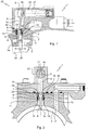
- a passage 8, in this case a bore 8, is formed through the enclosure wall 3 and extends between the first and second zones 2, 4.
- a guide piece 7 is arranged inside this. passage 8 and is assembled in a removable manner vis-à-vis the enclosure wall 3.
- the control rod 5 passes through the passage 8 by passing through this guide piece which is recessed in its center.
- a first end 5a of the rod 5 is placed in the first zone 2 and a second end 5b of the rod is placed in the second zone 4.
- Sealing means 6, in this case at least one O-ring 22, are provided. arranged around and against the control rod 5 to oppose the passage of fluid, along the rod 5, between the first and second zones 2, 4.
- These sealing means 6 are assembled inside the part guide 7 and are shaped to allow a relative movement of the rod 5 with respect to the guide piece 7 while providing the seal in the guide piece, along the rod 5, between said first and second zones 2, 4.
- the first zone 2 is intended to receive a fluid at high hydraulic pressure and the second zone 4 is intended to receive a lower hydraulic pressure fluid relative to said high pressure.
- the guiding in movement of the control rod 5 relative to the wall of the hydraulic enclosure 3 is carried out via the guide piece 7 inserted in the bore 8 of the wall 3.
- the sealing means 6 which are inside this guide part 7 are removable with respect to this part which is itself removable with respect to the wall 3.
- the invention makes it possible to simplify the manufacture and maintenance of the control system 1. It also makes it possible to reduce wear and the risk of damaging the hydraulic part 3 ′ containing the high pressure chamber during maintenance operations.
- control system 1 is integrated into an aircraft landing gear actuator 25, according to the invention and the hydraulic part 3 ', the wall 3 of which delimits the hydraulic enclosure, is a solid part of the actuator.
- the seal 6 can be redone around the rod while retaining the part 3 'assembled to the rest of the undercarriage. This limits the duration of immobilization of the undercarriage and the need for scrapping the hydraulic part 3 '.
- this actuator 25 comprises a hydraulic piston 26 slidably mounted inside the first zone 2 of the hydraulic enclosure. A first part of the control rod 5 extends in this first zone 2 to be moved. either directly or indirectly by said piston 26 during its movement.
- a portion of the piston 26 carries an index 28 which moves with the piston 26 during at least some of its axial movements in the first zone 2.
- This index 28 is arranged to come into contact against the control rod. 5 in order to move it relative to the guide piece 7 and thus control an action in the second zone 4, outside the enclosure.
- a metal part 27 is placed in this second zone 4 in order to be moved there by a part of the control rod 5 which is located in this second zone 4, as a function of the sliding position of the hydraulic piston 26.
- the actuator 25 comprises means for detecting the movement of the metal part 27 in this second zone 4. These detection means are arranged away from the first high pressure zone and may comprise an electronic sensor of the magnetic sensor type and /. or capacitive detecting the proximity of the metal part 27 relative to the sensor.
- control system 1 makes it possible to control, from inside the enclosure, the movement of the metal part 27 outside the enclosure.
- detection of the movement of the metal part 27 makes it possible to detect a sliding position of the hydraulic piston 26 in the enclosure.
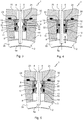
- the guide part 7 is a part of revolution extending along an axis of revolution coincident with the main axis of the bore 8 in which this guide piece 7 is inserted / fitted.
- the first axial stop means 9 are produced by a countersink 13 formed in the bore 8 and extend along the entire guide piece 7. The axial end of the guide piece facing towards / on the side of the first zone 2, bears axially against the bottom of this counterbore 13.
- the guide part 7 has an external annular shoulder 12 located in the vicinity of its end which is oriented towards the second zone 4.
- the counterbore 13 extends along only a portion of the part 7 and is formed at the end of the bore 8 which is oriented towards / placed on the side of the second zone 4.
- the external annular shoulder 12 bears axially against this counterbore 13.
- the first axial stop means 9 comprise an elastic ring 14 extending in an annular groove 15 formed at the internal periphery of the bore 8. This ring is arranged between the guide piece 7 and the first zone 2 and s' opposes the movement of the guide piece 7 towards the first zone 2.
- a hollow outer block 23 is arranged so as to define said second zone 4 outside the enclosure.
- This second zone 4 is mainly formed inside the hollow outer block 23.
- This hollow outer block 23 is removably assembled against said enclosure wall 3 and outside this enclosure 3.
- a part of this outer block hollow 23 extends opposite the bore 8 so as to form the second axial stop means 24 which prevent the extraction of the guide piece 7 from the bore 8.
- At least one annular seal 30 of the bore 8 is placed between the wall 3 and one face of the hollow outer block 23 so as to provide all around the end of the bore 8, a seal between the wall 3 and this hollow outer block 23.
- This seal 30 opposes the passage of fluid between the second zone 4 and the outside of the system according to the invention.
- the control rod 5 has a ball 16 formed between end ends 5a, 5b of this control rod 5.
- the guide piece 7 comprises a ball seat 17 formed inside the guide piece 7 and against which is positioned the ball 16 to allow the control rod 5 to pivot about a central point of the ball and relative to the ball seat 17 which forms an annular support of the ball 16.
- the ball 16 has an annular surface forming a portion of a sphere and the rod 5 comprises a first portion 18 extending from the ball 16 to the first zone 2 into which it enters and a second portion 19 extending from the ball joint. 16 until the second zone 4 into which it enters.
- the first portion 18 is arranged to control from the first zone 2, the pivoting of the ball joint 16 with respect to the ball seat 17 and consequently the movement of the second portion 19 in the second zone. This causes the sliding movement of the metal part 27 in this second zone.
- the guide piece 7 has a countersink 20 formed between the ball seat 17 and the second zone 4.
- An annular retaining ring 21 is placed inside this countersink 20 so as to wedge the ball 16 between the ball seat. 17 and this annular retaining ring 21.
- the O-ring 22 is positioned between the ring 21 and the ball seat 17. This seal 22 which surrounds the ball joint is in radial contact against the ball joint 16 and against an annular internal flat surface of the countersinking produced in the guide part. .
- This O-ring 22 has a thickness e less than a distance d formed axially between an annular internal flat surface of the counterbore 20 and the annular retaining ring 21.
- this O-ring 22 is clamped radially between the ball joint 16 and the guide piece 7 while being able to move axially between the annular internal flat surface of the counterbore 20 and the annular retaining ring 21. This allows a slight adaptation of the seal to possible defects in the shape of the ball joint. Machining precision can thus be minimized.
- the part of the hollow outer block 23 which extends opposite the bore 8 also comes opposite the annular retaining ring 21 to oppose the extraction of the ring. retaining ring 21 vis-à-vis the counterbore 20 produced in the guide part 7.
- a method of renovating an aircraft landing gear actuator as defined above comprises a step of making said bore 8 in an already existing passage of the enclosure wall 3 and a step of inserting said guide part 7 rod in this bore so that the control rod extends between the first and second zones 2 and 4. Once this guide piece 7 wedged between the first and second axial stop means 24, the rod can then be guided while ensuring that the seal between zones 2 and 4 is respected.
- This process makes it possible to renovate the seal between the first and second zones 2, 4 at a lower cost. Scrapping of the hydraulic part 3 'can be avoided. and the life of the landing gear can thus be prolonged at low cost.
Landscapes
- Engineering & Computer Science (AREA)
- General Engineering & Computer Science (AREA)
- Mechanical Engineering (AREA)
- Physics & Mathematics (AREA)
- Fluid Mechanics (AREA)
- Aviation & Aerospace Engineering (AREA)
- Actuator (AREA)
- Sealing Devices (AREA)
Applications Claiming Priority (1)
| Application Number | Priority Date | Filing Date | Title |
|---|---|---|---|
| FR1550799A FR3032174B1 (fr) | 2015-02-02 | 2015-02-02 | Systeme de commande comportant une tige de commande |
Publications (2)
| Publication Number | Publication Date |
|---|---|
| EP3051149A1 EP3051149A1 (fr) | 2016-08-03 |
| EP3051149B1 true EP3051149B1 (fr) | 2021-06-02 |
Family
ID=53008677
Family Applications (1)
| Application Number | Title | Priority Date | Filing Date |
|---|---|---|---|
| EP16152489.7A Active EP3051149B1 (fr) | 2015-02-02 | 2016-01-22 | Actionneur d'atterrisseur d'aéronef comprenant un système de commande comportant une tige de commande |
Country Status (5)
| Country | Link |
|---|---|
| US (1) | US10131420B2 (enExample) |
| EP (1) | EP3051149B1 (enExample) |
| CA (1) | CA2918786C (enExample) |
| ES (1) | ES2879967T3 (enExample) |
| FR (1) | FR3032174B1 (enExample) |
Cited By (1)
| Publication number | Priority date | Publication date | Assignee | Title |
|---|---|---|---|---|
| DE202022100277U1 (de) | 2022-01-19 | 2023-04-21 | Liebherr-Aerospace Lindenberg Gmbh | Verriegelungserfassungseinrichtung |
Families Citing this family (1)
| Publication number | Priority date | Publication date | Assignee | Title |
|---|---|---|---|---|
| US11548620B2 (en) | 2019-03-11 | 2023-01-10 | Parker-Hannifin Corporation | Electromechanically actuated control rod for flight vehicles |
Family Cites Families (10)
| Publication number | Priority date | Publication date | Assignee | Title |
|---|---|---|---|---|
| US3047682A (en) * | 1958-07-18 | 1962-07-31 | Cutler Hammer Inc | Electric switches |
| US3787149A (en) * | 1971-03-24 | 1974-01-22 | G Levey | Pump for zinc-rich materials or the like |
| DD101469A1 (enExample) * | 1972-12-21 | 1973-11-12 | ||
| DE3317888C1 (de) * | 1983-05-17 | 1984-11-08 | Festo-Maschinenfabrik Gottlieb Stoll, 7300 Esslingen | Mechanischer Endlagenabtaster |
| US4559865A (en) * | 1984-02-21 | 1985-12-24 | Decoto Aircraft Inc. | Device to transfer mechanical motion across fluid barrier |
| JPS63243509A (ja) * | 1987-03-27 | 1988-10-11 | Smc Corp | 位置検出機構付シリンダ |
| US5201639A (en) * | 1992-03-03 | 1993-04-13 | Reineck Donald R | In-line hand pump device |
| CA2576801C (en) * | 2004-08-30 | 2014-04-22 | Messier-Dowty Inc. | Lock sensor for an internally locking actuator |
| WO2011046351A2 (ko) * | 2009-10-13 | 2011-04-21 | Kim Gi-Chan | 공압 및 유압을 이용한 구동기 |
| US20140102293A1 (en) * | 2012-10-12 | 2014-04-17 | Spx Corporation | Self aligning cylinder piston and rod bearing and method of manufacture thereof |
-
2015
- 2015-02-02 FR FR1550799A patent/FR3032174B1/fr active Active
-
2016
- 2016-01-22 ES ES16152489T patent/ES2879967T3/es active Active
- 2016-01-22 EP EP16152489.7A patent/EP3051149B1/fr active Active
- 2016-01-22 CA CA2918786A patent/CA2918786C/fr active Active
- 2016-02-01 US US15/012,339 patent/US10131420B2/en active Active
Non-Patent Citations (1)
| Title |
|---|
| None * |
Cited By (1)
| Publication number | Priority date | Publication date | Assignee | Title |
|---|---|---|---|---|
| DE202022100277U1 (de) | 2022-01-19 | 2023-04-21 | Liebherr-Aerospace Lindenberg Gmbh | Verriegelungserfassungseinrichtung |
Also Published As
| Publication number | Publication date |
|---|---|
| US10131420B2 (en) | 2018-11-20 |
| CA2918786A1 (fr) | 2016-08-02 |
| FR3032174B1 (fr) | 2018-10-12 |
| ES2879967T3 (es) | 2021-11-23 |
| CA2918786C (fr) | 2018-01-02 |
| FR3032174A1 (enExample) | 2016-08-05 |
| US20160221665A1 (en) | 2016-08-04 |
| EP3051149A1 (fr) | 2016-08-03 |
Similar Documents
| Publication | Publication Date | Title |
|---|---|---|
| US8960643B2 (en) | Double offset ball member usable in ball valves and other flow control applications | |
| FR2970307A1 (fr) | Procede ameliore de positionnement de tubes bout a bout | |
| US20120211690A1 (en) | Ball Valves and Associated Methods | |
| FR3032256A1 (enExample) | ||
| EP3051149B1 (fr) | Actionneur d'atterrisseur d'aéronef comprenant un système de commande comportant une tige de commande | |
| FR3023613A1 (fr) | Procede de detection d'une fuite d'un joint dynamique dans un atterrisseur d'aeronef. | |
| WO2021001314A1 (fr) | Joint filete avec epaulement realise par fabrication additive | |
| EP3755925A1 (fr) | Assemblage d'étanchéité métallique pour l'étanchéité entre un arbre tournant et un bâti fixe | |
| EP3017210B1 (fr) | Dispositif de freinage par piston à fonction de recul total | |
| KR101656564B1 (ko) | 가공과 조립이 용이한 암커플러 | |
| JP5899056B2 (ja) | 転がり軸受 | |
| JPWO2019093363A1 (ja) | 弁 | |
| FR2940827A1 (fr) | Robinet a obturateur spherique a double decentrement de grandes dimensions, notamment un robinet de garde de turbine de controle hydroelectrique | |
| EP3135951B1 (fr) | Actionneur télescopique linéaire | |
| FR3004232A1 (fr) | Robinet integre dans un reseau de distribution de fluide, reseau et installation de conversion d'energie comprenant un tel robinet | |
| CN202118024U (zh) | 缸底油路切断阀 | |
| FR2979406A1 (fr) | Dispositif permettant d'assurer l'etancheite pour plusieurs canaux hydrauliques, procedes de fabrication et procede de montage d'un tel dispositif | |
| JP6270393B2 (ja) | 仕切弁と仕切弁のシートリングの固定方法 | |
| FR2820187A1 (fr) | Robinet a tournant spherique et procedes de montage et de demontage de son organe de manoeuvre |
Legal Events
| Date | Code | Title | Description |
|---|---|---|---|
| PUAI | Public reference made under article 153(3) epc to a published international application that has entered the european phase |
Free format text: ORIGINAL CODE: 0009012 |
|
| AK | Designated contracting states |
Kind code of ref document: A1 Designated state(s): AL AT BE BG CH CY CZ DE DK EE ES FI FR GB GR HR HU IE IS IT LI LT LU LV MC MK MT NL NO PL PT RO RS SE SI SK SM TR |
|
| AX | Request for extension of the european patent |
Extension state: BA ME |
|
| RAP1 | Party data changed (applicant data changed or rights of an application transferred) |
Owner name: SAFRAN LANDING SYSTEMS |
|
| RAP1 | Party data changed (applicant data changed or rights of an application transferred) |
Owner name: SAFRAN LANDING SYSTEMS |
|
| STAA | Information on the status of an ep patent application or granted ep patent |
Free format text: STATUS: REQUEST FOR EXAMINATION WAS MADE |
|
| 17P | Request for examination filed |
Effective date: 20170130 |
|
| RBV | Designated contracting states (corrected) |
Designated state(s): AL AT BE BG CH CY CZ DE DK EE ES FI FR GB GR HR HU IE IS IT LI LT LU LV MC MK MT NL NO PL PT RO RS SE SI SK SM TR |
|
| STAA | Information on the status of an ep patent application or granted ep patent |
Free format text: STATUS: EXAMINATION IS IN PROGRESS |
|
| 17Q | First examination report despatched |
Effective date: 20191220 |
|
| GRAP | Despatch of communication of intention to grant a patent |
Free format text: ORIGINAL CODE: EPIDOSNIGR1 |
|
| STAA | Information on the status of an ep patent application or granted ep patent |
Free format text: STATUS: GRANT OF PATENT IS INTENDED |
|
| INTG | Intention to grant announced |
Effective date: 20200731 |
|
| RIC1 | Information provided on ipc code assigned before grant |
Ipc: F15B 15/28 20060101AFI20200717BHEP Ipc: F16J 15/18 20060101ALI20200717BHEP Ipc: B64C 25/22 20060101ALI20200717BHEP |
|
| GRAJ | Information related to disapproval of communication of intention to grant by the applicant or resumption of examination proceedings by the epo deleted |
Free format text: ORIGINAL CODE: EPIDOSDIGR1 |
|
| STAA | Information on the status of an ep patent application or granted ep patent |
Free format text: STATUS: EXAMINATION IS IN PROGRESS |
|
| GRAP | Despatch of communication of intention to grant a patent |
Free format text: ORIGINAL CODE: EPIDOSNIGR1 |
|
| STAA | Information on the status of an ep patent application or granted ep patent |
Free format text: STATUS: GRANT OF PATENT IS INTENDED |
|
| INTC | Intention to grant announced (deleted) | ||
| INTG | Intention to grant announced |
Effective date: 20201222 |
|
| GRAS | Grant fee paid |
Free format text: ORIGINAL CODE: EPIDOSNIGR3 |
|
| GRAA | (expected) grant |
Free format text: ORIGINAL CODE: 0009210 |
|
| STAA | Information on the status of an ep patent application or granted ep patent |
Free format text: STATUS: THE PATENT HAS BEEN GRANTED |
|
| REG | Reference to a national code |
Ref country code: CH Ref legal event code: EP |
|
| AK | Designated contracting states |
Kind code of ref document: B1 Designated state(s): AL AT BE BG CH CY CZ DE DK EE ES FI FR GB GR HR HU IE IS IT LI LT LU LV MC MK MT NL NO PL PT RO RS SE SI SK SM TR |
|
| REG | Reference to a national code |
Ref country code: GB Ref legal event code: FG4D Free format text: NOT ENGLISH |
|
| REG | Reference to a national code |
Ref country code: AT Ref legal event code: REF Ref document number: 1398714 Country of ref document: AT Kind code of ref document: T Effective date: 20210615 |
|
| REG | Reference to a national code |
Ref country code: IE Ref legal event code: FG4D Free format text: LANGUAGE OF EP DOCUMENT: FRENCH |
|
| REG | Reference to a national code |
Ref country code: DE Ref legal event code: R096 Ref document number: 602016058691 Country of ref document: DE |
|
| REG | Reference to a national code |
Ref country code: LT Ref legal event code: MG9D |
|
| PG25 | Lapsed in a contracting state [announced via postgrant information from national office to epo] |
Ref country code: HR Free format text: LAPSE BECAUSE OF FAILURE TO SUBMIT A TRANSLATION OF THE DESCRIPTION OR TO PAY THE FEE WITHIN THE PRESCRIBED TIME-LIMIT Effective date: 20210602 Ref country code: BG Free format text: LAPSE BECAUSE OF FAILURE TO SUBMIT A TRANSLATION OF THE DESCRIPTION OR TO PAY THE FEE WITHIN THE PRESCRIBED TIME-LIMIT Effective date: 20210902 Ref country code: LT Free format text: LAPSE BECAUSE OF FAILURE TO SUBMIT A TRANSLATION OF THE DESCRIPTION OR TO PAY THE FEE WITHIN THE PRESCRIBED TIME-LIMIT Effective date: 20210602 Ref country code: FI Free format text: LAPSE BECAUSE OF FAILURE TO SUBMIT A TRANSLATION OF THE DESCRIPTION OR TO PAY THE FEE WITHIN THE PRESCRIBED TIME-LIMIT Effective date: 20210602 |
|
| REG | Reference to a national code |
Ref country code: NL Ref legal event code: MP Effective date: 20210602 |
|
| REG | Reference to a national code |
Ref country code: AT Ref legal event code: MK05 Ref document number: 1398714 Country of ref document: AT Kind code of ref document: T Effective date: 20210602 |
|
| REG | Reference to a national code |
Ref country code: ES Ref legal event code: FG2A Ref document number: 2879967 Country of ref document: ES Kind code of ref document: T3 Effective date: 20211123 |
|
| PG25 | Lapsed in a contracting state [announced via postgrant information from national office to epo] |
Ref country code: RS Free format text: LAPSE BECAUSE OF FAILURE TO SUBMIT A TRANSLATION OF THE DESCRIPTION OR TO PAY THE FEE WITHIN THE PRESCRIBED TIME-LIMIT Effective date: 20210602 Ref country code: SE Free format text: LAPSE BECAUSE OF FAILURE TO SUBMIT A TRANSLATION OF THE DESCRIPTION OR TO PAY THE FEE WITHIN THE PRESCRIBED TIME-LIMIT Effective date: 20210602 Ref country code: NO Free format text: LAPSE BECAUSE OF FAILURE TO SUBMIT A TRANSLATION OF THE DESCRIPTION OR TO PAY THE FEE WITHIN THE PRESCRIBED TIME-LIMIT Effective date: 20210902 Ref country code: PL Free format text: LAPSE BECAUSE OF FAILURE TO SUBMIT A TRANSLATION OF THE DESCRIPTION OR TO PAY THE FEE WITHIN THE PRESCRIBED TIME-LIMIT Effective date: 20210602 Ref country code: LV Free format text: LAPSE BECAUSE OF FAILURE TO SUBMIT A TRANSLATION OF THE DESCRIPTION OR TO PAY THE FEE WITHIN THE PRESCRIBED TIME-LIMIT Effective date: 20210602 Ref country code: GR Free format text: LAPSE BECAUSE OF FAILURE TO SUBMIT A TRANSLATION OF THE DESCRIPTION OR TO PAY THE FEE WITHIN THE PRESCRIBED TIME-LIMIT Effective date: 20210903 |
|
| PG25 | Lapsed in a contracting state [announced via postgrant information from national office to epo] |
Ref country code: NL Free format text: LAPSE BECAUSE OF FAILURE TO SUBMIT A TRANSLATION OF THE DESCRIPTION OR TO PAY THE FEE WITHIN THE PRESCRIBED TIME-LIMIT Effective date: 20210602 Ref country code: PT Free format text: LAPSE BECAUSE OF FAILURE TO SUBMIT A TRANSLATION OF THE DESCRIPTION OR TO PAY THE FEE WITHIN THE PRESCRIBED TIME-LIMIT Effective date: 20211004 Ref country code: RO Free format text: LAPSE BECAUSE OF FAILURE TO SUBMIT A TRANSLATION OF THE DESCRIPTION OR TO PAY THE FEE WITHIN THE PRESCRIBED TIME-LIMIT Effective date: 20210602 Ref country code: AT Free format text: LAPSE BECAUSE OF FAILURE TO SUBMIT A TRANSLATION OF THE DESCRIPTION OR TO PAY THE FEE WITHIN THE PRESCRIBED TIME-LIMIT Effective date: 20210602 Ref country code: SM Free format text: LAPSE BECAUSE OF FAILURE TO SUBMIT A TRANSLATION OF THE DESCRIPTION OR TO PAY THE FEE WITHIN THE PRESCRIBED TIME-LIMIT Effective date: 20210602 Ref country code: SK Free format text: LAPSE BECAUSE OF FAILURE TO SUBMIT A TRANSLATION OF THE DESCRIPTION OR TO PAY THE FEE WITHIN THE PRESCRIBED TIME-LIMIT Effective date: 20210602 Ref country code: CZ Free format text: LAPSE BECAUSE OF FAILURE TO SUBMIT A TRANSLATION OF THE DESCRIPTION OR TO PAY THE FEE WITHIN THE PRESCRIBED TIME-LIMIT Effective date: 20210602 Ref country code: EE Free format text: LAPSE BECAUSE OF FAILURE TO SUBMIT A TRANSLATION OF THE DESCRIPTION OR TO PAY THE FEE WITHIN THE PRESCRIBED TIME-LIMIT Effective date: 20210602 |
|
| REG | Reference to a national code |
Ref country code: DE Ref legal event code: R097 Ref document number: 602016058691 Country of ref document: DE |
|
| PLBE | No opposition filed within time limit |
Free format text: ORIGINAL CODE: 0009261 |
|
| STAA | Information on the status of an ep patent application or granted ep patent |
Free format text: STATUS: NO OPPOSITION FILED WITHIN TIME LIMIT |
|
| PG25 | Lapsed in a contracting state [announced via postgrant information from national office to epo] |
Ref country code: DK Free format text: LAPSE BECAUSE OF FAILURE TO SUBMIT A TRANSLATION OF THE DESCRIPTION OR TO PAY THE FEE WITHIN THE PRESCRIBED TIME-LIMIT Effective date: 20210602 |
|
| 26N | No opposition filed |
Effective date: 20220303 |
|
| PG25 | Lapsed in a contracting state [announced via postgrant information from national office to epo] |
Ref country code: AL Free format text: LAPSE BECAUSE OF FAILURE TO SUBMIT A TRANSLATION OF THE DESCRIPTION OR TO PAY THE FEE WITHIN THE PRESCRIBED TIME-LIMIT Effective date: 20210602 |
|
| PG25 | Lapsed in a contracting state [announced via postgrant information from national office to epo] |
Ref country code: MC Free format text: LAPSE BECAUSE OF FAILURE TO SUBMIT A TRANSLATION OF THE DESCRIPTION OR TO PAY THE FEE WITHIN THE PRESCRIBED TIME-LIMIT Effective date: 20210602 |
|
| REG | Reference to a national code |
Ref country code: CH Ref legal event code: PL |
|
| REG | Reference to a national code |
Ref country code: BE Ref legal event code: MM Effective date: 20220131 |
|
| PG25 | Lapsed in a contracting state [announced via postgrant information from national office to epo] |
Ref country code: LU Free format text: LAPSE BECAUSE OF NON-PAYMENT OF DUE FEES Effective date: 20220122 |
|
| PG25 | Lapsed in a contracting state [announced via postgrant information from national office to epo] |
Ref country code: BE Free format text: LAPSE BECAUSE OF NON-PAYMENT OF DUE FEES Effective date: 20220131 |
|
| PG25 | Lapsed in a contracting state [announced via postgrant information from national office to epo] |
Ref country code: LI Free format text: LAPSE BECAUSE OF NON-PAYMENT OF DUE FEES Effective date: 20220131 Ref country code: CH Free format text: LAPSE BECAUSE OF NON-PAYMENT OF DUE FEES Effective date: 20220131 |
|
| PG25 | Lapsed in a contracting state [announced via postgrant information from national office to epo] |
Ref country code: IE Free format text: LAPSE BECAUSE OF NON-PAYMENT OF DUE FEES Effective date: 20220122 |
|
| PG25 | Lapsed in a contracting state [announced via postgrant information from national office to epo] |
Ref country code: HU Free format text: LAPSE BECAUSE OF FAILURE TO SUBMIT A TRANSLATION OF THE DESCRIPTION OR TO PAY THE FEE WITHIN THE PRESCRIBED TIME-LIMIT; INVALID AB INITIO Effective date: 20160122 |
|
| PG25 | Lapsed in a contracting state [announced via postgrant information from national office to epo] |
Ref country code: MK Free format text: LAPSE BECAUSE OF FAILURE TO SUBMIT A TRANSLATION OF THE DESCRIPTION OR TO PAY THE FEE WITHIN THE PRESCRIBED TIME-LIMIT Effective date: 20210602 Ref country code: CY Free format text: LAPSE BECAUSE OF FAILURE TO SUBMIT A TRANSLATION OF THE DESCRIPTION OR TO PAY THE FEE WITHIN THE PRESCRIBED TIME-LIMIT Effective date: 20210602 |
|
| PG25 | Lapsed in a contracting state [announced via postgrant information from national office to epo] |
Ref country code: TR Free format text: LAPSE BECAUSE OF FAILURE TO SUBMIT A TRANSLATION OF THE DESCRIPTION OR TO PAY THE FEE WITHIN THE PRESCRIBED TIME-LIMIT Effective date: 20210602 |
|
| PG25 | Lapsed in a contracting state [announced via postgrant information from national office to epo] |
Ref country code: MT Free format text: LAPSE BECAUSE OF FAILURE TO SUBMIT A TRANSLATION OF THE DESCRIPTION OR TO PAY THE FEE WITHIN THE PRESCRIBED TIME-LIMIT Effective date: 20210602 |
|
| PGFP | Annual fee paid to national office [announced via postgrant information from national office to epo] |
Ref country code: GB Payment date: 20241219 Year of fee payment: 10 |
|
| PGFP | Annual fee paid to national office [announced via postgrant information from national office to epo] |
Ref country code: FR Payment date: 20241219 Year of fee payment: 10 |
|
| PGFP | Annual fee paid to national office [announced via postgrant information from national office to epo] |
Ref country code: DE Payment date: 20241218 Year of fee payment: 10 |
|
| PGFP | Annual fee paid to national office [announced via postgrant information from national office to epo] |
Ref country code: ES Payment date: 20250203 Year of fee payment: 10 |
|
| PGFP | Annual fee paid to national office [announced via postgrant information from national office to epo] |
Ref country code: IT Payment date: 20250107 Year of fee payment: 10 |