EP3050751B1 - Procédé et dispositif d'assistance d'un conducteur de véhicule automobile, en particulier d'un véhicule utilitaire - Google Patents
Procédé et dispositif d'assistance d'un conducteur de véhicule automobile, en particulier d'un véhicule utilitaire Download PDFInfo
- Publication number
- EP3050751B1 EP3050751B1 EP16000177.2A EP16000177A EP3050751B1 EP 3050751 B1 EP3050751 B1 EP 3050751B1 EP 16000177 A EP16000177 A EP 16000177A EP 3050751 B1 EP3050751 B1 EP 3050751B1
- Authority
- EP
- European Patent Office
- Prior art keywords
- commercial vehicle
- loop
- loading
- control device
- vehicle
- Prior art date
- Legal status (The legal status is an assumption and is not a legal conclusion. Google has not performed a legal analysis and makes no representation as to the accuracy of the status listed.)
- Active
Links
Images



Classifications
-
- B—PERFORMING OPERATIONS; TRANSPORTING
- B60—VEHICLES IN GENERAL
- B60Q—ARRANGEMENT OF SIGNALLING OR LIGHTING DEVICES, THE MOUNTING OR SUPPORTING THEREOF OR CIRCUITS THEREFOR, FOR VEHICLES IN GENERAL
- B60Q1/00—Arrangement of optical signalling or lighting devices, the mounting or supporting thereof or circuits therefor
- B60Q1/26—Arrangement of optical signalling or lighting devices, the mounting or supporting thereof or circuits therefor the devices being primarily intended to indicate the vehicle, or parts thereof, or to give signals, to other traffic
- B60Q1/32—Arrangement of optical signalling or lighting devices, the mounting or supporting thereof or circuits therefor the devices being primarily intended to indicate the vehicle, or parts thereof, or to give signals, to other traffic for indicating vehicle sides, e.g. clearance lights
-
- B—PERFORMING OPERATIONS; TRANSPORTING
- B60—VEHICLES IN GENERAL
- B60P—VEHICLES ADAPTED FOR LOAD TRANSPORTATION OR TO TRANSPORT, TO CARRY, OR TO COMPRISE SPECIAL LOADS OR OBJECTS
- B60P1/00—Vehicles predominantly for transporting loads and modified to facilitate loading, consolidating the load, or unloading
- B60P1/64—Vehicles predominantly for transporting loads and modified to facilitate loading, consolidating the load, or unloading the load supporting or containing element being readily removable
-
- B—PERFORMING OPERATIONS; TRANSPORTING
- B60—VEHICLES IN GENERAL
- B60Q—ARRANGEMENT OF SIGNALLING OR LIGHTING DEVICES, THE MOUNTING OR SUPPORTING THEREOF OR CIRCUITS THEREFOR, FOR VEHICLES IN GENERAL
- B60Q1/00—Arrangement of optical signalling or lighting devices, the mounting or supporting thereof or circuits therefor
- B60Q1/26—Arrangement of optical signalling or lighting devices, the mounting or supporting thereof or circuits therefor the devices being primarily intended to indicate the vehicle, or parts thereof, or to give signals, to other traffic
- B60Q1/46—Arrangement of optical signalling or lighting devices, the mounting or supporting thereof or circuits therefor the devices being primarily intended to indicate the vehicle, or parts thereof, or to give signals, to other traffic for giving flashing caution signals during drive, other than signalling change of direction, e.g. flashing the headlights or hazard lights
Definitions
- the invention relates to two alternative methods for supporting a driver of a commercial vehicle according to patent claims 1 and 8 and a commercial vehicle for carrying out the method according to patent claim 14.
- Such a regulation or control is, for example, from the publication DE 10 2007 006 263 A1 is known, which discloses side lighting for a truck, in which at least one lighting unit arranged on the outside of the truck and designed as a luminous strip is provided. Depending on the desired lighting effect or the desired light intensity, for example, a white light or a light of a different color can be reproduced by means of the light strip.
- the light strip can also be controlled or regulated as a function of a signal from a control unit of a direction indicator of the vehicle. In this way, for example, when a turn signal lever of the vehicle is operated, not only the direction indicator, but the entire light strip represent the direction indicator.
- the object of the invention is to provide a method and a device for supporting a driver of a vehicle, in particular a commercial vehicle, in which the function of the side marker lights is expanded or improved in a simple manner.
- a method for supporting a driver of a commercial vehicle wherein the vehicle, seen in the vehicle transverse direction, has at least one side marker light on each side of the vehicle, and wherein a regulating and/or control device is provided, by means of which the Lighting of the side marker lights is regulated or controlled.
- the regulation and/or control device is switched to a hazard warning flasher mode in the event of a warning situation in the vehicle, in which the side marker lights are controlled in such a way that they display a flashing warning signal.
- the function of the side marker lights is expanded or improved in a simple manner, since a flashing warning signal is now displayed with the side marker lights provided on both sides of the vehicle when the vehicle is in a warning situation.
- the flashing of the side marker lights in particular in connection with a conventional hazard warning system, warns people in the vicinity of the vehicle particularly clearly and reliably of the warning situation or of the vehicle.
- an actuating device that can be actuated by the driver of the vehicle, in particular a button and/or a switch, is provided, by actuating which the regulating and/or control device is switched to the hazard warning mode and/or by the actuation of which the hazard warning mode is switched off.
- the driver of the vehicle can switch the hazard warning flashing mode on and/or off at any time he so desires. For example, he can switch on the hazard warning flasher mode if the vehicle has broken down or if repair work needs to be carried out on the vehicle. The driver can also switch off the hazard warning flasher mode, for example, if he does not consider it necessary to display the flashing warning signal using the side marker lights.
- the vehicle has a loading and/or unloading device on, by means of which the vehicle can be loaded and / or unloaded, with a loading and/or unloading detection device is provided, by means of which a loading and/or unloading process of the vehicle is detected and/or detected, wherein the regulating and/or control device when loading and/or is detected and/or detected Unloading automatically or automatically switches to hazard warning mode.
- a loading and/or unloading detection device is provided, by means of which a loading and/or unloading process of the vehicle is detected and/or detected, wherein the regulating and/or control device when loading and/or is detected and/or detected Unloading automatically or automatically switches to hazard warning mode.
- At least one transport device, in particular a container, parked in a parking area arranged outside of the vehicle is parked and/or arranged on a loading area of the vehicle by means of the loading and/or unloading device.
- at least one transport device arranged on a loading area of the vehicle, in particular a container can be set down by means of the loading and/or unloading device in a set-up area arranged outside of the vehicle.
- Such loading and/or unloading processes have a particularly high risk potential, which means that switching on the hazard warning flasher mode is particularly important here.
- the vehicle can be designed, for example, as a roll-off tipper or as a skip handler.
- the loading and/or unloading device has a level control device, by means of which the vehicle level is adjusted in a defined manner for loading and/or unloading the vehicle, starting from a basic position or a driving position, it being preferably provided that the current vehicle level can be determined by means of the loading and/or unloading detection device. Using the current level of the vehicle, the loading and/or unloading process can be reliably and easily detected or recorded with the loading and/or unloading detection device.
- the current vehicle level can preferably be determined via at least one current hydraulic and/or pneumatic pressure value of the hydraulically and/or pneumatically actuable level control device using the loading and/or unloading detection device. The current vehicle level can use such a pressure value can be determined reliably and easily. It is preferably provided that the loading and/or unloading detection device has a measuring device, by means of which the at least one hydraulic and/or pneumatic pressure value can be measured.
- the at least one hydraulic and/or pneumatic pressure value can be determined particularly easily.
- the vehicle level is first lowered from the basic position by means of the level control device.
- the vehicle is then driven with its loading area under the transport device parked in the parking area and finally the vehicle level is raised back to the basic position by picking up the transport device by means of the level control device.
- the regulating and/or control device automatically switches to the hazard warning mode immediately after or during the lowering of the vehicle level and the hazard warning mode is switched off again at the latest after the vehicle level has been raised to the basic position. In this way, the hazard warning flasher mode is reliably switched on when the loading process using the level control device has a particularly high risk potential.
- the vehicle level can be lowered starting from the basic position, initially by parking a transport device arranged on the loading area of the vehicle at the parking area by means of the level control device. The vehicle is then driven away from the parking area and finally the vehicle level is raised back to the basic position by means of the level control device. It is preferably provided that the regulating and/or control device automatically switches to the hazard warning mode at the latest when the vehicle level is being lowered and the hazard warning mode is switched off again at the latest after the vehicle level has been raised to the basic position.
- an actuating device that can be actuated by the driver of the vehicle, in particular a button and/or a switch, which can be actuated to bring the adjusted vehicle level back into the basic position, with the regulating and/or control device being activated automatically when the actuating device is actuated or automatically switches off the hazard warning mode.
- the driver of the vehicle reliably signals that the loading and/or unloading process and thus also the warning situation have ended.
- the automatic switching off of the hazard warning flasher mode then ensures that the hazard warning flasher mode is switched off in a particularly convenient and reliable manner.
- an actuating device that can be actuated by the driver of the vehicle, in particular a button and/or a switch, is provided Unloading device for generating a hydraulic and / or pneumatic pressure can be activated and / or deactivated.
- the regulating and/or control device When the pressure-generating device is activated, the regulating and/or control device then preferably automatically or automatically switches to the hazard warning flasher mode.
- the driver of the vehicle signals reliably and unambiguously that a vehicle loading process is about to start.
- the regulating and/or control device can automatically or automatically switch off the hazard warning mode when the pressure-generating device is deactivated. This reliably and clearly signals that the loading and/or unloading process has ended.
- an actuating device that can be actuated by the driver of the vehicle, in particular a button and/or a switch, is provided, by actuating which a hazard warning system of the vehicle can be activated and/or deactivated.
- the regulating and/or control device When the hazard warning system is activated, the regulating and/or control device then preferably automatically or automatically switches to the hazard warning mode. In this way, by activating the hazard warning system using the actuating device, the driver can also switch the regulating and/or control device to the hazard warning mode. Alternatively and/or additionally, the regulating and/or control device can also automatically or automatically switch off the hazard warning flasher mode when the hazard warning flasher system is deactivated. Thus, when the hazard warning system is deactivated, the driver also switches off the hazard warning mode by means of the actuating device.
- the regulation and/or control device automatically switches to a basic mode in which the side marker lights are controlled in such a way that they display a permanent light signal.
- the vehicle is marked or marked with a permanent light signal by means of the side marker lights when the vehicle is not in a warning situation.
- the driving light can be a parking light, low beam, or high beam of the vehicle, for example be educated. However, it is preferably formed by the side lights of the vehicle.
- a device for assisting a driver of a vehicle, in particular a commercial vehicle, wherein the vehicle, seen in the vehicle transverse direction, has at least one side marker light on each side of the vehicle, and wherein a control and / or control device is provided, by means of which the lighting of the side marker lights can be regulated and / or controlled.
- the regulation and/or control device can be switched to a warning flashing mode in a warning situation of the vehicle, in which the side marker lights can be controlled by the regulation and/or control device such that they display a flashing warning signal.
- a vehicle embodied here by way of example as a truck 1 is shown.
- the truck 1 has a 1 only schematically indicated loading and unloading device 3, by means of which the truck 1 can be loaded and unloaded.
- the truck 1 is designed here as a roll-off tipper, which can be loaded with a roll-off container 5 .
- the truck 1 could also be designed here, for example, as a skip loader.
- the loading and unloading device 3 can be actuated hydraulically here, for example, and has a pressure-generating device, designed here, for example, as a pump 7, by means of which a hydraulic fluid of the hydraulically actuated loading and unloading device 3 can be pressurized.
- the pump 7 can be activated here by means of an in 1 activated and deactivated by the driver of the truck 1, which is indicated by dashed lines and can be actuated.
- the actuating device 9 can be designed, for example, as a button or as a switch.
- the truck 1 also has a plurality of side marker lights 11, here by way of example six, by means of which the truck 1 can be externally marked or identified.
- a plurality of side marker lights 11 are provided laterally outside on each side 12 of the vehicle.
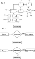
- the side marker lights 11 are illuminated by means of an in 3 Regulated and/or controlled by the regulating and/or control device 13 shown.
- the regulation and/or control device 13 can be switched here, for example, to a basic mode in which the side marker lights 11 are controlled by the regulation and/or control device 13 in such a way that they display a permanent light signal.
- the regulation and/or control device 13 can also be switched to a hazard warning mode, in which the side marker lights 11 are controlled by the regulation and/or control device 13 in such a way that they display a flashing warning signal.
- the hazard warning mode is only switched on when the truck is 1 is in a warning situation. If the truck 1 is not in a warning situation, the closed-loop and/or open-loop control device 13 automatically switches to the basic mode, for example. Warning situations are formed here, for example, by a loading process and an unloading process of the truck 1 .
- the flashing of the side marker lights 11 ensures that people in the vicinity of the truck 1 stay away from the danger zones 14 during a loading or unloading process of the truck 1 .
- the regulating and/or control device 13 is also connected to the pump 7 in terms of signals. As a result, the regulating and/or control device 13 is signaled or notified of an activation and a deactivation of the pump 7 . If the pump 7 is activated by the driver of the truck 1, this is a clear indication of the beginning of a loading or unloading process of the truck 1. Conversely, the deactivation of the pump 7 is a clear indication of the end of a loading or unloading process of the truck 1 When the pump 7 is activated, the regulating and/or control device 13 then automatically or automatically switches to the hazard warning mode. When the pump 7 is deactivated, the regulating and/or control device 13 automatically switches off the hazard warning mode and switches on the basic mode.
- the regulating and/or control device 13 In an initial situation, the regulating and/or control device 13 is in the basic mode, in which the side marker lights 11 display a permanent light signal. The pump 7 is deactivated. If the regulation and/or control device 13 is then not signaled that the pump 7 has been activated by means of a signal S pump of the pump 7, the regulation and/or control device 13 remains in the basic mode. If an activation of the pump 7 is signaled to the regulating and/or control device 13 by means of the signal S pump , the regulating and/or control device 13 automatically or automatically switches to the hazard warning mode.
- the regulation and/or control device 13 If the regulation and/or control device 13 has switched to the hazard warning mode, it remains in the hazard warning mode if the regulation and/or control device 13 is not signaled to deactivate the pump 7 by means of the signal S pump of the pump 7 . If the closed-loop and/or open-loop control device 13 switched to the hazard warning mode is signaled that the pump 7 has been deactivated by means of the signal S pump of the pump 7, the open-loop and/or control device 13 switches back to the basic mode.
- the truck 1 also has an actuation device 17, for example a button or a switch, which can be actuated by the driver of the truck 1 and which can be used to activate and deactivate a conventional hazard warning system of the truck 1.
- an actuation device 17 for example a button or a switch, which can be actuated by the driver of the truck 1 and which can be used to activate and deactivate a conventional hazard warning system of the truck 1.
- all direction indicators 19 of the truck 1, four in this case by way of example are switched on so that they display a flashing warning signal.
- the actuating device 17 is also connected here in terms of signals to the regulating and/or control device 13 in such a way that the regulating and/or control device 13 is informed or signaled when the hazard warning lights of the truck 1 are activated and deactivated.
- the regulating and/or control device 13 When the hazard warning system is activated, the regulating and/or control device 13 then automatically or automatically switches to the hazard warning mode. When the hazard warning system is deactivated, the regulating and/or control device 13 automatically switches off the hazard warning mode and switches to the basic mode.
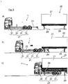
- FIG 5 a second embodiment of the truck 1 is shown.
- the truck 1 is here, in comparison to the first embodiment of the truck 1, not designed as a roll-off tipper. Instead, the in figure 5 Truck 1 shown has a level control device 21, by means of which, for loading and unloading the truck 1, the vehicle level of the truck 1, starting from an in Figure 5c shown basic position or driving position is adjusted in a defined manner.
- FIG. 5a to 5c a loading process of the truck 1 by means of the level control device 21 is shown here as an example.
- the truck 1 according to Figure 5a first lowered the vehicle level of the truck 1 starting from the basic position by means of the level control device 21.
- the truck 1 according to Figure 5b driven with its loading area 23 under an interchangeable container 27 parked in a parking area 25 .
- the vehicle level of the truck 1 according to Figure 5c raised again to the basic position with the inclusion of the interchangeable container 27 .
- the supports 29 fixed to the interchangeable container 27 are dismantled.
- the truck 1 is unloaded in reverse order.
- the level control device 21 here only by way of example, for adjusting the vehicle level several, here by way of example eight, designed as air bellows 31 lifting devices.
- the vehicle level of the truck 1 is therefore controlled or regulated here via the air pressure in the air bellows 31 .
- the second embodiment of the truck 1 has a loading and unloading detection device 15, by means of which a loading or unloading process of the truck 1 can be detected or detected.
- the loading and unloading detection device 15 includes here, for example, an evaluation unit 32 and several measuring devices 33 connected to the evaluation unit 32 by means of which the air pressure in the air bellows 31 is measured.
- a measuring device 33 is assigned to each air bellows 31 .
- the air pressures measured by the measuring devices 33 are transmitted to the evaluation unit 32, by means of which the current vehicle level of the truck 1 can then be determined from the measured air pressures.
- the evaluation unit 21 can then use the current vehicle level of the truck 1 to recognize or record whether the truck 1 is currently in a loading or unloading process or not.
- the evaluation unit 32 is also connected to the regulating and/or control device 13 in terms of signals. If the loading and unloading detection device 15 recognizes or detects a loading or unloading process of the truck 1, this is signaled or communicated to the regulating and/or control device 13. When a loading process is recognized or recorded, the regulating and/or control device 13 automatically switches to the hazard warning mode immediately after the vehicle level of the truck 1 has been lowered. When the unloading process of the truck 1 is recognized or recorded, the regulating and/or control device 13 automatically switches to the hazard warning mode while the vehicle level is being lowered.
- the truck 1 also has an actuating device 35, for example a button or a switch, which can be actuated by the driver of the truck 1 and which can be actuated to bring the adjusted vehicle level of the truck 1 back into the basic position.
- the actuating device 35 is connected to the regulating and/or control device 13 in terms of signals in such a way that the regulating and/or control device 13 is informed or signaled that the actuating device 35 has been actuated.
- the regulating and/or control device 13 here automatically switches off the hazard warning mode and switches on the basic mode.
Landscapes
- Engineering & Computer Science (AREA)
- Mechanical Engineering (AREA)
- Transportation (AREA)
- Lighting Device Outwards From Vehicle And Optical Signal (AREA)
Claims (14)
- Procédé d'assistance au conducteur d'un véhicule utilitaire, le véhicule utilitaire (1) comportant au moins un feu de position latéral (11) de chaque côté (12) du véhicule latéralement à l'extérieur par référence à la direction transversale (y) du véhicule, et une unité de régulation et/ou de commande (13) étant prévue pour réguler et/ou commander l'allumage des feux de position latéraux (11), l'unité de régulation et/ou de commande (13) étant commutée en cas de situation de détresse du véhicule utilitaire (1) dans un mode de détresse dans lequel les feux de position latéraux (11) sont activés de façon à afficher un signal de détresse clignotant et, si le mode de détresse est désactivé et qu'un feu de croisement du véhicule utilitaire est allumé, l'unité de régulation et/ou de commande (13) commutant automatiquement dans un mode de base dans lequel les feux de position latéraux (11) sont activés de façon à afficher un signal lumineux permanent,le véhicule utilitaire (1) comportant un dispositif de charge et/ou de décharge (3) permettant de charger et/ou décharger le véhicule utilitaire (1), etun processus de charge et/ou de décharge du véhicule utilitaire (1) formant une situation de détresse,une unité de reconnaissance de charge et/ou de décharge (15) étant prévue qui permet de reconnaître et/ou détecter un processus de charge et/ou de décharge du véhicule utilitaire (1),l'unité de régulation et/ou de commande (13) commutant automatiquement dans le mode de détresse lorsqu'un processus de charge et/ou de décharge est reconnu et/ou détecté, etle dispositif de charge et/ ou de décharge (3) comportant une unité de régulation de niveau (21) qui permet de régler le niveau du véhicule utilitaire d'une manière définie à partir d'une position de base afin de charger et/ou décharger le véhicule utilitaire (1).
- Procédé selon la revendication 1, caractérisé en ce que le niveau actuel du véhicule utilitaire peut être déterminé au moyen de l'unité de reconnaissance de charge et/ou de décharge (15).
- Procédé selon la revendication 2, caractérisé en ce que le niveau actuel du véhicule utilitaire peut être déterminé au moyen de l'unité de reconnaissance de charge et /ou de décharge (15) par le biais d'au moins une valeur de pression hydraulique et/ou pneumatique actuelle de l'unité de régulation de niveau à actionnement hydraulique et/ou pneumatique (21), l'unité de reconnaissance de charge et/ou de décharge (15) étant de préférence prévue pour comporter une unité de mesure (33) permettant de mesurer au moins une valeur de pression hydraulique et/ou pneumatique actuelle.
- Procédé selon l'une des revendications précédentes, caractérisé en ce que, afin de charger le véhicule utilitaire (1), au moins une unité de transport (5, 27), notamment un conteneur, placée au niveau d'une aire de placement (25) disposée à l'extérieur du véhicule utilitaire (1) est placée et/ou disposée sur une surface de charge (23) du véhicule utilitaire (1) au moyen du dispositif de charge et/ou de décharge (3).
- Procédé selon la revendication 4, caractérisé en ce que, afin de charger le véhicule utilitaire (1), le niveau du véhicule utilitaire, à partir de la position de base, est d'abord abaissé au moyen de l'unité de régulation de niveau (21) de façon à amener ensuite le véhicule utilitaire (1) avec sa surface de charge (23) au-dessous de l'unité de transport (27) placée dans la zone de placement (25) et à élever enfin à nouveau le niveau du véhicule utilitaire jusqu'à la position de base par réception de l'unité de transport (27) au moyen de l'unité de régulation de niveau (21), l'unité de régulation et/ou de commande (13) étant de préférence prévue pour commuter automatiquement dans le mode de détresse immédiatement après ou pendant l'abaissement du niveau du véhicule utilitaire et repasser dans la position de base du mode de détresse au plus tard après relèvement du niveau du véhicule utilitaire.
- Procédé selon la revendication 4 ou 5, caractérisé en ce que, afin de décharger le véhicule utilitaire (1), le niveau du véhicule utilitaire est d'abord abaissé à partir de la position de base par placement d'une unité de transport (27), disposée sur la surface de charge (23) du véhicule utilitaire (1), au niveau de la zone de placement (25) au moyen de l'unité de régulation de niveau (21), en ce que le véhicule utilitaire (1) est ensuite éloigné de la zone de placement (25) et en ce que le niveau du véhicule utilitaire est enfin à nouveau relevé jusqu'à la position de base au moyen de l'unité de régulation de niveau (21), l'unité de régulation et/ou de commande (13) étant de préférence prévue pour commuter automatiquement dans le mode de détresse au plus tard lorsque le niveau du véhicule utilitaire est abaissé et repasser dans la position de base au plus tard après relèvement du niveau du véhicule utilitaire.
- Procédé selon l'une des revendications 2 à 6, caractérisé en ce qu'une unité d'actionnement (35), notamment un bouton et/ou un commutateur, actionnable par le conducteur du véhicule utilitaire (1), est prévu qui permet, lorsqu'il est actionné, de ramener le niveau réglé du véhicule utilitaire dans la position de base, l'unité de régulation et/ou de commande (13) désactivant automatiquement le mode de détresse lorsque l'unité d'actionnement (35) est actionnée.
- Procédé d'assistance au conducteur d'un véhicule utilitaire, le véhicule utilitaire (1) comportant au moins un feu de position latéral (11) de chaque côté (12) du véhicule latéralement à l'extérieur par référence à la direction transversale (y) du véhicule, et une unité de régulation et/ou de commande (13) étant prévue pour réguler et/ou commander l'allumage des feux de position latéraux (11), l'unité de régulation et/ou de commande (13) étant commutée en cas de situation de détresse du véhicule utilitaire (1) dans un mode de détresse dans lequel les feux de position latéraux (11) sont activés de façon à afficher un signal de détresse clignotant et, si le mode de détresse est désactivé et qu'un feu de croisement du véhicule utilitaire est allumé, l'unité de régulation et/ou de commande (13) commutant automatiquement dans un mode de base dans lequel les feux de position latéraux (11) sont activés de façon à afficher un signal lumineux permanent,le véhicule utilitaire (1) comportant un dispositif de charge et/ou de décharge (3) permettant de charger et/ou décharger le véhicule utilitaire (1), etun processus de charge et/ou de décharge du véhicule utilitaire (1) formant une situation de détresse,une unité de reconnaissance de charge et/ou de décharge (15) étant prévue qui permet de reconnaître et/ou détecter un processus de charge et/ou de décharge du véhicule utilitaire (1),l'unité de régulation et/ou de commande (13) commutant automatiquement dans le mode de détresse lorsqu'un processus de charge et/ou de décharge est reconnu et/ou détecté, etle dispositif de charge et/ ou de décharge (3) comportant une unité de régulation de niveau (21) qui permet de régler le niveau du véhicule utilitaire d'une manière définie à partir d'une position de base afin de charger et/ou décharger le véhicule utilitaire (1),une unité d'actionnement (9), actionnable par le conducteur du véhicule utilitaire, étant prévu qui permet, lorsqu'elle est actionnée, d'activer une unité de génération de pression (7) du dispositif de charge et/ou de décharge actionnable hydrauliquement et/ou pneumatiquement (3) pour générer une pression hydraulique et/ou pneumatique.
- Procédé selon la revendication 8, caractérisé en ce que, lorsque l'unité de génération de pression (7) est activée, l'unité de régulation et/ou de commande (13) commute automatiquement dans le mode de détresse et/ou en ce que, lorsque l'unité de génération de pression (7) est désactivée, l'unité de régulation et/ou de commande (13) désactive automatiquement le mode de détresse.
- Procédé selon l'une des revendications précédentes, caractérisé en ce que, pour décharger le véhicule utilitaire (1), au moins une unité de transport (5, 27), en particulier un conteneur, disposée sur une surface de charge (23) du véhicule utilitaire (1), est placée au niveau d'une zone de placement (25) disposée à l'extérieur du véhicule utilitaire (1) au moyen de l'unité de charge et/ou de décharge (3).
- Procédé selon l'une des revendications précédentes, caractérisé en ce qu'une unité d'actionnement (17), en particulier un bouton et/ou un commutateur, actionnable par le conducteur du véhicule utilitaire, est prévue qui permet, lorsqu'elle est actionnée, d'activer et de désactiver un système de détresse (19) du véhicule utilitaire (1).
- Procédé selon la revendication 11, caractérisé en ce que, lorsque le système de détresse (19) est activé, l'unité de régulation et/ou de commande (13) commute automatiquement dans le mode de détresse et/ou en ce que l'unité de régulation et/ou de commande (13) désactive automatiquement le mode de détresse lorsque le système de détresse (19) est désactivé.
- Procédé selon l'une des revendications précédentes, caractérisé en ce qu'une unité d'actionnement (17), en particulier un bouton et/ou un commutateur, actionnable par le conducteur du véhicule utilitaire (1), est prévue qui permet, lorsqu'elle est actionnée, de commuter l'unité de régulation et/ou de commande (13) dans le mode de détresse et/ou de désactiver le mode de détresse.
- Véhicule utilitaire destiné à mettre en oeuvre un procédé selon l'une des revendications 1 ou 8,le véhicule utilitaire (1) comportant au moins un feu de position latéral (11) de chaque côté (12) du véhicule latéralement à l'extérieur par référence à la direction transversale (y) du véhicule, et une unité de régulation et/ou de commande (13) étant prévue pour réguler et/ou commander l'allumage des feux de position latéraux (11), l'unité de régulation et/ou de commande (13) étant commutée en cas de situation de détresse du véhicule utilitaire (1) dans un mode de détresse dans lequel les feux de position latéraux (11) sont activés de façon à afficher un signal de détresse clignotant et, si le mode de détresse est désactivé et qu'un feu de croisement du véhicule utilitaire est allumé, l'unité de régulation et/ou de commande (13) commutant automatiquement dans un mode de base dans lequel les feux de position latéraux (11) sont activés de façon à afficher un signal lumineux permanent,le véhicule utilitaire (1) comportant un dispositif de charge et/ou de décharge (3) permettant de charger et/ou décharger le véhicule utilitaire (1), etun processus de charge et/ou de décharge du véhicule utilitaire (1) formant une situation de détresse,une unité de reconnaissance de charge et/ou de décharge (15) étant prévue qui permet de reconnaître et/ou détecter un processus de charge et/ou de décharge du véhicule utilitaire (1),l'unité de régulation et/ou de commande (13) commutant automatiquement dans le mode de détresse lorsqu'un processus de charge et/ou de décharge est reconnu et/ou détecté, etle dispositif de charge et/ ou de décharge (3) comportant une unité de régulation de niveau (21) qui permet de régler le niveau du véhicule utilitaire d'une manière définie à partir d'une position de base afin de charger et/ou décharger le véhicule utilitaire (1),une unité d'actionnement (9), actionnable par le conducteur du véhicule utilitaire, étant prévu qui permet, lorsqu'elle est actionnée, d'activer une unité de génération de pression (7) du dispositif de charge et/ou de décharge actionnable hydrauliquement et/ou pneumatiquement (3) pour générer une pression hydraulique et/ou pneumatique.
Applications Claiming Priority (1)
| Application Number | Priority Date | Filing Date | Title |
|---|---|---|---|
| DE102015001051.4A DE102015001051A1 (de) | 2015-01-29 | 2015-01-29 | Verfahren und Vorrichtung zur Unterstützung eines Fahrers eines Fahrzeugs, insbesondere eines Nutzfahrzeugs |
Publications (3)
| Publication Number | Publication Date |
|---|---|
| EP3050751A2 EP3050751A2 (fr) | 2016-08-03 |
| EP3050751A3 EP3050751A3 (fr) | 2016-12-28 |
| EP3050751B1 true EP3050751B1 (fr) | 2022-08-24 |
Family
ID=55310615
Family Applications (1)
| Application Number | Title | Priority Date | Filing Date |
|---|---|---|---|
| EP16000177.2A Active EP3050751B1 (fr) | 2015-01-29 | 2016-01-26 | Procédé et dispositif d'assistance d'un conducteur de véhicule automobile, en particulier d'un véhicule utilitaire |
Country Status (2)
| Country | Link |
|---|---|
| EP (1) | EP3050751B1 (fr) |
| DE (1) | DE102015001051A1 (fr) |
Families Citing this family (1)
| Publication number | Priority date | Publication date | Assignee | Title |
|---|---|---|---|---|
| FR3084637B1 (fr) * | 2018-07-31 | 2022-05-20 | Milestone Factory Sa | Chassis de vehicule de transport d'au moins un conteneur |
Citations (2)
| Publication number | Priority date | Publication date | Assignee | Title |
|---|---|---|---|---|
| DE10237669A1 (de) * | 2002-08-16 | 2004-02-26 | Wilfried Stephan | SBVfL (Seitenblinkvorrichtung für Lastzüge) |
| DE102005037710A1 (de) * | 2005-08-10 | 2007-02-22 | Daimlerchrysler Ag | Nutzfahrzeug mit Fahrerhaus und Seitenleuchte |
Family Cites Families (8)
| Publication number | Priority date | Publication date | Assignee | Title |
|---|---|---|---|---|
| DE1804791C3 (de) * | 1968-10-24 | 1975-05-28 | Robert Bosch Gmbh, 7000 Stuttgart | Transporteinrichtung für die selbsttätige Beförderung von Lasten |
| US4964022A (en) * | 1989-04-10 | 1990-10-16 | Robert Lane | Bus side light system |
| DE19543632C2 (de) * | 1995-10-09 | 1998-04-23 | Erich Mueller | Einrichtung zum Transport von Stückgütern durch ein leichtes Fahrzeug |
| US8552852B1 (en) * | 2005-11-22 | 2013-10-08 | Allen D Hertz | Trailer hitch receiver safety light system |
| DE102007006263A1 (de) | 2007-02-08 | 2008-08-14 | Daimler Ag | Seitenbeleuchtung für einen Lastkraftwagen |
| US9132770B2 (en) * | 2012-04-05 | 2015-09-15 | Oshkosh Corporation | Vehicle illumination system |
| DE102012020441A1 (de) * | 2012-10-18 | 2014-04-24 | Man Truck & Bus Ag | Beleuchtungs- und Signaleinrichtung eines mehrspurigen Kraftfahrzeugs |
| US20140297173A1 (en) * | 2014-06-18 | 2014-10-02 | Ming-Chih Li | System for alerting automobile driver when opening door |
-
2015
- 2015-01-29 DE DE102015001051.4A patent/DE102015001051A1/de not_active Withdrawn
-
2016
- 2016-01-26 EP EP16000177.2A patent/EP3050751B1/fr active Active
Patent Citations (2)
| Publication number | Priority date | Publication date | Assignee | Title |
|---|---|---|---|---|
| DE10237669A1 (de) * | 2002-08-16 | 2004-02-26 | Wilfried Stephan | SBVfL (Seitenblinkvorrichtung für Lastzüge) |
| DE102005037710A1 (de) * | 2005-08-10 | 2007-02-22 | Daimlerchrysler Ag | Nutzfahrzeug mit Fahrerhaus und Seitenleuchte |
Also Published As
| Publication number | Publication date |
|---|---|
| EP3050751A3 (fr) | 2016-12-28 |
| EP3050751A2 (fr) | 2016-08-03 |
| DE102015001051A1 (de) | 2016-08-04 |
Similar Documents
| Publication | Publication Date | Title |
|---|---|---|
| EP0482298B1 (fr) | Procédure et dispositif pour effectuer une opération de nivellement d'un corps, en particulier une pièce de véhicule | |
| DE102011000668C5 (de) | Verfahren zur Fahrerunterstützung bei einem Andock-Vorgang eines Nutzfahrzeugs an einer Rampe | |
| EP2113482B1 (fr) | Dispositif de levage | |
| DE112005003713T5 (de) | Aufzugsystemsteuerung, die auf Schachtzugangsdetektion anspricht | |
| DE102013225033A1 (de) | Fahrzeug mit einem Fahrerassistenzsystem und Verfahren zum Betreiben eines solchen Fahrzeugs | |
| DE10149090A1 (de) | Geschwindigkeitsregler mit Anzeigeeinrichtung | |
| EP3511472A2 (fr) | Machine de construction, en particulier engin de terrassement doté d'un pupitre de commande | |
| DE10339245A1 (de) | Bremssteuersystem für ein Fahrzeug | |
| EP3645356B1 (fr) | Méthode pour opérer un frein de stationnement électro-pneumatique d'un véhicule | |
| DE102013017213A1 (de) | Fahrzeug und Verfahren zum Ausleuchten eines Bereichs hinter einem Fahrzeug | |
| DE102007020124B4 (de) | Vorrichtung und Symbole zur Bedienung von Funktionen eines Fahrzeugs | |
| EP0773136B2 (fr) | Plate-forme de hayon et procédé pour sa commande | |
| EP3050751A2 (fr) | Procédé et dispositif d'assistance d'un conducteur de véhicule automobile, en particulier d'un véhicule utilitaire | |
| DE102012014761A1 (de) | Bedienstelle und Verfahren zur Betätigung von Lichtfunktionen | |
| DE202018105112U1 (de) | Automatischer Anhängevorgangsspiegel | |
| EP3204260A1 (fr) | Procédé de commande d'un véhicule à moteur doté d'un capteur optique et véhicule à moteur | |
| DE102011101714A1 (de) | Verfahren einer elektrohydraulischen Hubwerksregelung und Bedieneinheit für eine elektrohydraulische Hubwerksregelung | |
| EP1622443B1 (fr) | Dispositif et procede de commande du systeme de levage d'un vehicule agricole | |
| DE102011114803A1 (de) | Verfahren zum Betrieb einer Kraftfahrzeugbremse mit automatischer Haltefunktion | |
| DE102017213031B4 (de) | Verfahren zum Betreiben eines Fahrerassistenzsystems zum Rangieren eines Kraftwagens, Fahrerassistenzsystem sowie Steuerungseinrichtung | |
| DE102016215245B4 (de) | Verfahren zur Durchführung eines automatischen oder semi-automatischen Parkvorgangs eines Kraftfahrzeugs und Kraftfahrzeug | |
| DE102024120689A1 (de) | Verfahren und System zur Unterstützung des Fahrers eines Fahrzeugs mit Anhänger bei der Rückwärtsfahrt | |
| DE19882967B3 (de) | Vorrichtung die anzeigt, wann das Gewicht einer Ladung während des Beladens eines Nutzfahrzeuges einen maximalen Wert erreicht | |
| DE202004004805U1 (de) | Mobilkran mit Scheinwerfer und/oder Kamera | |
| EP2573038A1 (fr) | Système de commande automatique pour un camion pour la charge et / ou déchargé |
Legal Events
| Date | Code | Title | Description |
|---|---|---|---|
| PUAI | Public reference made under article 153(3) epc to a published international application that has entered the european phase |
Free format text: ORIGINAL CODE: 0009012 |
|
| AK | Designated contracting states |
Kind code of ref document: A2 Designated state(s): AL AT BE BG CH CY CZ DE DK EE ES FI FR GB GR HR HU IE IS IT LI LT LU LV MC MK MT NL NO PL PT RO RS SE SI SK SM TR |
|
| AX | Request for extension of the european patent |
Extension state: BA ME |
|
| PUAL | Search report despatched |
Free format text: ORIGINAL CODE: 0009013 |
|
| AK | Designated contracting states |
Kind code of ref document: A3 Designated state(s): AL AT BE BG CH CY CZ DE DK EE ES FI FR GB GR HR HU IE IS IT LI LT LU LV MC MK MT NL NO PL PT RO RS SE SI SK SM TR |
|
| AX | Request for extension of the european patent |
Extension state: BA ME |
|
| RIC1 | Information provided on ipc code assigned before grant |
Ipc: B60Q 1/46 20060101ALI20161124BHEP Ipc: B60P 1/64 20060101ALI20161124BHEP Ipc: B60Q 1/32 20060101AFI20161124BHEP |
|
| STAA | Information on the status of an ep patent application or granted ep patent |
Free format text: STATUS: REQUEST FOR EXAMINATION WAS MADE |
|
| 17P | Request for examination filed |
Effective date: 20170628 |
|
| RBV | Designated contracting states (corrected) |
Designated state(s): AL AT BE BG CH CY CZ DE DK EE ES FI FR GB GR HR HU IE IS IT LI LT LU LV MC MK MT NL NO PL PT RO RS SE SI SK SM TR |
|
| RAP1 | Party data changed (applicant data changed or rights of an application transferred) |
Owner name: MAN TRUCK & BUS SE |
|
| R17P | Request for examination filed (corrected) |
Effective date: 20170628 |
|
| STAA | Information on the status of an ep patent application or granted ep patent |
Free format text: STATUS: EXAMINATION IS IN PROGRESS |
|
| 17Q | First examination report despatched |
Effective date: 20200707 |
|
| GRAP | Despatch of communication of intention to grant a patent |
Free format text: ORIGINAL CODE: EPIDOSNIGR1 |
|
| STAA | Information on the status of an ep patent application or granted ep patent |
Free format text: STATUS: GRANT OF PATENT IS INTENDED |
|
| INTG | Intention to grant announced |
Effective date: 20220316 |
|
| GRAS | Grant fee paid |
Free format text: ORIGINAL CODE: EPIDOSNIGR3 |
|
| GRAA | (expected) grant |
Free format text: ORIGINAL CODE: 0009210 |
|
| STAA | Information on the status of an ep patent application or granted ep patent |
Free format text: STATUS: THE PATENT HAS BEEN GRANTED |
|
| AK | Designated contracting states |
Kind code of ref document: B1 Designated state(s): AL AT BE BG CH CY CZ DE DK EE ES FI FR GB GR HR HU IE IS IT LI LT LU LV MC MK MT NL NO PL PT RO RS SE SI SK SM TR |
|
| REG | Reference to a national code |
Ref country code: CH Ref legal event code: EP |
|
| REG | Reference to a national code |
Ref country code: DE Ref legal event code: R096 Ref document number: 502016015197 Country of ref document: DE |
|
| REG | Reference to a national code |
Ref country code: IE Ref legal event code: FG4D Free format text: LANGUAGE OF EP DOCUMENT: GERMAN |
|
| REG | Reference to a national code |
Ref country code: AT Ref legal event code: REF Ref document number: 1513434 Country of ref document: AT Kind code of ref document: T Effective date: 20220915 |
|
| REG | Reference to a national code |
Ref country code: NL Ref legal event code: FP |
|
| REG | Reference to a national code |
Ref country code: SE Ref legal event code: TRGR |
|
| REG | Reference to a national code |
Ref country code: LT Ref legal event code: MG9D |
|
| PG25 | Lapsed in a contracting state [announced via postgrant information from national office to epo] |
Ref country code: RS Free format text: LAPSE BECAUSE OF FAILURE TO SUBMIT A TRANSLATION OF THE DESCRIPTION OR TO PAY THE FEE WITHIN THE PRESCRIBED TIME-LIMIT Effective date: 20220824 Ref country code: PT Free format text: LAPSE BECAUSE OF FAILURE TO SUBMIT A TRANSLATION OF THE DESCRIPTION OR TO PAY THE FEE WITHIN THE PRESCRIBED TIME-LIMIT Effective date: 20221226 Ref country code: NO Free format text: LAPSE BECAUSE OF FAILURE TO SUBMIT A TRANSLATION OF THE DESCRIPTION OR TO PAY THE FEE WITHIN THE PRESCRIBED TIME-LIMIT Effective date: 20221124 Ref country code: LV Free format text: LAPSE BECAUSE OF FAILURE TO SUBMIT A TRANSLATION OF THE DESCRIPTION OR TO PAY THE FEE WITHIN THE PRESCRIBED TIME-LIMIT Effective date: 20220824 Ref country code: LT Free format text: LAPSE BECAUSE OF FAILURE TO SUBMIT A TRANSLATION OF THE DESCRIPTION OR TO PAY THE FEE WITHIN THE PRESCRIBED TIME-LIMIT Effective date: 20220824 Ref country code: FI Free format text: LAPSE BECAUSE OF FAILURE TO SUBMIT A TRANSLATION OF THE DESCRIPTION OR TO PAY THE FEE WITHIN THE PRESCRIBED TIME-LIMIT Effective date: 20220824 Ref country code: ES Free format text: LAPSE BECAUSE OF FAILURE TO SUBMIT A TRANSLATION OF THE DESCRIPTION OR TO PAY THE FEE WITHIN THE PRESCRIBED TIME-LIMIT Effective date: 20220824 |
|
| PG25 | Lapsed in a contracting state [announced via postgrant information from national office to epo] |
Ref country code: PL Free format text: LAPSE BECAUSE OF FAILURE TO SUBMIT A TRANSLATION OF THE DESCRIPTION OR TO PAY THE FEE WITHIN THE PRESCRIBED TIME-LIMIT Effective date: 20220824 Ref country code: IS Free format text: LAPSE BECAUSE OF FAILURE TO SUBMIT A TRANSLATION OF THE DESCRIPTION OR TO PAY THE FEE WITHIN THE PRESCRIBED TIME-LIMIT Effective date: 20221224 Ref country code: HR Free format text: LAPSE BECAUSE OF FAILURE TO SUBMIT A TRANSLATION OF THE DESCRIPTION OR TO PAY THE FEE WITHIN THE PRESCRIBED TIME-LIMIT Effective date: 20220824 Ref country code: GR Free format text: LAPSE BECAUSE OF FAILURE TO SUBMIT A TRANSLATION OF THE DESCRIPTION OR TO PAY THE FEE WITHIN THE PRESCRIBED TIME-LIMIT Effective date: 20221125 |
|
| PG25 | Lapsed in a contracting state [announced via postgrant information from national office to epo] |
Ref country code: SM Free format text: LAPSE BECAUSE OF FAILURE TO SUBMIT A TRANSLATION OF THE DESCRIPTION OR TO PAY THE FEE WITHIN THE PRESCRIBED TIME-LIMIT Effective date: 20220824 Ref country code: RO Free format text: LAPSE BECAUSE OF FAILURE TO SUBMIT A TRANSLATION OF THE DESCRIPTION OR TO PAY THE FEE WITHIN THE PRESCRIBED TIME-LIMIT Effective date: 20220824 Ref country code: DK Free format text: LAPSE BECAUSE OF FAILURE TO SUBMIT A TRANSLATION OF THE DESCRIPTION OR TO PAY THE FEE WITHIN THE PRESCRIBED TIME-LIMIT Effective date: 20220824 Ref country code: CZ Free format text: LAPSE BECAUSE OF FAILURE TO SUBMIT A TRANSLATION OF THE DESCRIPTION OR TO PAY THE FEE WITHIN THE PRESCRIBED TIME-LIMIT Effective date: 20220824 |
|
| REG | Reference to a national code |
Ref country code: DE Ref legal event code: R097 Ref document number: 502016015197 Country of ref document: DE |
|
| PG25 | Lapsed in a contracting state [announced via postgrant information from national office to epo] |
Ref country code: SK Free format text: LAPSE BECAUSE OF FAILURE TO SUBMIT A TRANSLATION OF THE DESCRIPTION OR TO PAY THE FEE WITHIN THE PRESCRIBED TIME-LIMIT Effective date: 20220824 Ref country code: EE Free format text: LAPSE BECAUSE OF FAILURE TO SUBMIT A TRANSLATION OF THE DESCRIPTION OR TO PAY THE FEE WITHIN THE PRESCRIBED TIME-LIMIT Effective date: 20220824 |
|
| PG25 | Lapsed in a contracting state [announced via postgrant information from national office to epo] |
Ref country code: AL Free format text: LAPSE BECAUSE OF FAILURE TO SUBMIT A TRANSLATION OF THE DESCRIPTION OR TO PAY THE FEE WITHIN THE PRESCRIBED TIME-LIMIT Effective date: 20220824 |
|
| PLBE | No opposition filed within time limit |
Free format text: ORIGINAL CODE: 0009261 |
|
| STAA | Information on the status of an ep patent application or granted ep patent |
Free format text: STATUS: NO OPPOSITION FILED WITHIN TIME LIMIT |
|
| 26N | No opposition filed |
Effective date: 20230525 |
|
| PG25 | Lapsed in a contracting state [announced via postgrant information from national office to epo] |
Ref country code: SI Free format text: LAPSE BECAUSE OF FAILURE TO SUBMIT A TRANSLATION OF THE DESCRIPTION OR TO PAY THE FEE WITHIN THE PRESCRIBED TIME-LIMIT Effective date: 20220824 |
|
| REG | Reference to a national code |
Ref country code: CH Ref legal event code: PL |
|
| GBPC | Gb: european patent ceased through non-payment of renewal fee |
Effective date: 20230126 |
|
| PG25 | Lapsed in a contracting state [announced via postgrant information from national office to epo] |
Ref country code: LU Free format text: LAPSE BECAUSE OF NON-PAYMENT OF DUE FEES Effective date: 20230126 |
|
| REG | Reference to a national code |
Ref country code: BE Ref legal event code: MM Effective date: 20230131 |
|
| PG25 | Lapsed in a contracting state [announced via postgrant information from national office to epo] |
Ref country code: LI Free format text: LAPSE BECAUSE OF NON-PAYMENT OF DUE FEES Effective date: 20230131 Ref country code: GB Free format text: LAPSE BECAUSE OF NON-PAYMENT OF DUE FEES Effective date: 20230126 Ref country code: CH Free format text: LAPSE BECAUSE OF NON-PAYMENT OF DUE FEES Effective date: 20230131 |
|
| PG25 | Lapsed in a contracting state [announced via postgrant information from national office to epo] |
Ref country code: BE Free format text: LAPSE BECAUSE OF NON-PAYMENT OF DUE FEES Effective date: 20230131 |
|
| PG25 | Lapsed in a contracting state [announced via postgrant information from national office to epo] |
Ref country code: IE Free format text: LAPSE BECAUSE OF NON-PAYMENT OF DUE FEES Effective date: 20230126 |
|
| REG | Reference to a national code |
Ref country code: AT Ref legal event code: MM01 Ref document number: 1513434 Country of ref document: AT Kind code of ref document: T Effective date: 20230126 |
|
| PG25 | Lapsed in a contracting state [announced via postgrant information from national office to epo] |
Ref country code: AT Free format text: LAPSE BECAUSE OF NON-PAYMENT OF DUE FEES Effective date: 20230126 |
|
| PG25 | Lapsed in a contracting state [announced via postgrant information from national office to epo] |
Ref country code: AT Free format text: LAPSE BECAUSE OF NON-PAYMENT OF DUE FEES Effective date: 20230126 |
|
| PG25 | Lapsed in a contracting state [announced via postgrant information from national office to epo] |
Ref country code: MC Free format text: LAPSE BECAUSE OF FAILURE TO SUBMIT A TRANSLATION OF THE DESCRIPTION OR TO PAY THE FEE WITHIN THE PRESCRIBED TIME-LIMIT Effective date: 20220824 |
|
| PG25 | Lapsed in a contracting state [announced via postgrant information from national office to epo] |
Ref country code: MC Free format text: LAPSE BECAUSE OF FAILURE TO SUBMIT A TRANSLATION OF THE DESCRIPTION OR TO PAY THE FEE WITHIN THE PRESCRIBED TIME-LIMIT Effective date: 20220824 |
|
| PG25 | Lapsed in a contracting state [announced via postgrant information from national office to epo] |
Ref country code: BG Free format text: LAPSE BECAUSE OF FAILURE TO SUBMIT A TRANSLATION OF THE DESCRIPTION OR TO PAY THE FEE WITHIN THE PRESCRIBED TIME-LIMIT Effective date: 20220824 |
|
| PG25 | Lapsed in a contracting state [announced via postgrant information from national office to epo] |
Ref country code: BG Free format text: LAPSE BECAUSE OF FAILURE TO SUBMIT A TRANSLATION OF THE DESCRIPTION OR TO PAY THE FEE WITHIN THE PRESCRIBED TIME-LIMIT Effective date: 20220824 |
|
| PG25 | Lapsed in a contracting state [announced via postgrant information from national office to epo] |
Ref country code: CY Free format text: LAPSE BECAUSE OF FAILURE TO SUBMIT A TRANSLATION OF THE DESCRIPTION OR TO PAY THE FEE WITHIN THE PRESCRIBED TIME-LIMIT; INVALID AB INITIO Effective date: 20160126 |
|
| PG25 | Lapsed in a contracting state [announced via postgrant information from national office to epo] |
Ref country code: HU Free format text: LAPSE BECAUSE OF FAILURE TO SUBMIT A TRANSLATION OF THE DESCRIPTION OR TO PAY THE FEE WITHIN THE PRESCRIBED TIME-LIMIT; INVALID AB INITIO Effective date: 20160126 |
|
| PG25 | Lapsed in a contracting state [announced via postgrant information from national office to epo] |
Ref country code: TR Free format text: LAPSE BECAUSE OF FAILURE TO SUBMIT A TRANSLATION OF THE DESCRIPTION OR TO PAY THE FEE WITHIN THE PRESCRIBED TIME-LIMIT Effective date: 20220824 |
|
| PGFP | Annual fee paid to national office [announced via postgrant information from national office to epo] |
Ref country code: NL Payment date: 20260122 Year of fee payment: 11 |
|
| PGFP | Annual fee paid to national office [announced via postgrant information from national office to epo] |
Ref country code: SE Payment date: 20260126 Year of fee payment: 11 |
|
| PGFP | Annual fee paid to national office [announced via postgrant information from national office to epo] |
Ref country code: DE Payment date: 20260127 Year of fee payment: 11 |
|
| PGFP | Annual fee paid to national office [announced via postgrant information from national office to epo] |
Ref country code: IT Payment date: 20260123 Year of fee payment: 11 |
|
| PGFP | Annual fee paid to national office [announced via postgrant information from national office to epo] |
Ref country code: FR Payment date: 20260127 Year of fee payment: 11 |