EP0773136B2 - Plate-forme de hayon et procédé pour sa commande - Google Patents
Plate-forme de hayon et procédé pour sa commande Download PDFInfo
- Publication number
- EP0773136B2 EP0773136B2 EP96116394A EP96116394A EP0773136B2 EP 0773136 B2 EP0773136 B2 EP 0773136B2 EP 96116394 A EP96116394 A EP 96116394A EP 96116394 A EP96116394 A EP 96116394A EP 0773136 B2 EP0773136 B2 EP 0773136B2
- Authority
- EP
- European Patent Office
- Prior art keywords
- loading platform
- pivoting
- stored
- sensor
- tail lift
- Prior art date
- Legal status (The legal status is an assumption and is not a legal conclusion. Google has not performed a legal analysis and makes no representation as to the accuracy of the status listed.)
- Expired - Lifetime
Links
- 238000000034 method Methods 0.000 title claims abstract description 19
- 230000006870 function Effects 0.000 claims description 10
- 230000001960 triggered effect Effects 0.000 claims description 3
- 230000000977 initiatory effect Effects 0.000 claims 1
- 230000001419 dependent effect Effects 0.000 description 2
- QSHDDOUJBYECFT-UHFFFAOYSA-N mercury Chemical compound [Hg] QSHDDOUJBYECFT-UHFFFAOYSA-N 0.000 description 2
- 229910052753 mercury Inorganic materials 0.000 description 2
- 239000002689 soil Substances 0.000 description 2
- 238000006243 chemical reaction Methods 0.000 description 1
- 239000010720 hydraulic oil Substances 0.000 description 1
- 230000003446 memory effect Effects 0.000 description 1
- 238000012544 monitoring process Methods 0.000 description 1
- 238000004091 panning Methods 0.000 description 1
- 238000003825 pressing Methods 0.000 description 1
- 230000002265 prevention Effects 0.000 description 1
- 230000004044 response Effects 0.000 description 1
- 230000000284 resting effect Effects 0.000 description 1
Images

Classifications
-
- B—PERFORMING OPERATIONS; TRANSPORTING
- B60—VEHICLES IN GENERAL
- B60P—VEHICLES ADAPTED FOR LOAD TRANSPORTATION OR TO TRANSPORT, TO CARRY, OR TO COMPRISE SPECIAL LOADS OR OBJECTS
- B60P1/00—Vehicles predominantly for transporting loads and modified to facilitate loading, consolidating the load, or unloading
- B60P1/44—Vehicles predominantly for transporting loads and modified to facilitate loading, consolidating the load, or unloading having a loading platform thereon raising the load to the level of the load-transporting element
- B60P1/4471—General means for controlling movements of the loading platform, e.g. hydraulic systems
Definitions
- the invention relates to a method for controlling a tail lift according to the preamble of claim 1. Furthermore, the invention relates to a tail lift according to the preamble of claim. 7
- Tail lifts of the type discussed here serve to facilitate the loading and unloading of vehicles, in particular heavy objects.
- the tail lifts have a preferably hinged at the rear of a vehicle body, raised and lowered hinged loading platform.
- the loading platform In a rest position, in particular during the moving vehicle, the loading platform is raised and swung up into a vertical plane. The loading platform is then behind the rear wall of the vehicle body. In a loading position for loading and unloading the vehicle, the loading platform is swung down in a horizontal or almost horizontal position. By lowering the loading platform folded down in this way, the objects to be unloaded can be brought from the level of the vehicle bodywork to a lower level, in particular a ground level, on the other hand. Conversely, the loading platform is lifted to load the vehicle. When lowered to, for example, the ground loading platform usually deviates from the slope of the soil course.
- the loading platform is again pivoted in such a way that it rests essentially on the entire surface of the ground (tilt compensation). Therefore, before re-lifting the loading platform must first be swung up a bit again.
- Hubladebühen are already known in which the loading platform on level switch, in particular mercury switch has.
- the loading platform can be pivoted automatically in particular a horizontal pivot position.
- this inclination changes depending on the load of the loading platform. Because of this, it is necessary to change the inclination individually, namely, depending on the weight of each loaded or unloaded objects.
- the tilt switch would have to be changed on the loading platform in its position, which requires a disproportionate effort.
- a tail lift is known in which a collision of a trailing edge of the vehicle body is to be avoided with an adjacent edge of the loading platform.
- the loading platform is lowered slightly before pivoting. This lowered position can be stored in a control in the known tail lift and is automatically controlled when swinging back the loading platform.
- this tail lift there is also the problem that the placed in a completely resting on the ground position loading platform for lifting again manually must be placed in an approximately horizontal position so that objects located on the loading platform can not slip off this.
- the invention is based on the problem to provide a tail lift and a method for controlling the same, whereby a simpler and safer operation is guaranteed.
- a method for solving the problem underlying the invention comprises the measure of claim 1. Characterized in that according to the invention stored at least one pivot position of the loading platform and then automatically approached again, the operator needs only pretend this (only) pivot position. This swivel position is automatically approached in the following.
- the loading platform "remembers" quasi the predetermined, for example, when giving away from the rest position pivotal position, for example, it is automatically set again when swinging back from the adapted to the course of the floor inclination of the loading platform in the slope required for lifting.
- the position of the loading platform reached by a first, manually controlled pivoting remains stored until, due to the actuation of corresponding actuators, this inclination is changed.
- the respective desired inclination can be adjusted individually, without the need for any mechanical changes, such as conversion of a mercury switch, are required.
- This circuit stores the respective preset position and controls the automatic start of the same.
- the preset value of the pan position is stored until a new setting is made.
- the newly set value is then saved by overwriting the old value.
- the electronic control is used according to a development of the method according to the invention for carrying out additional functions, such as the extension and retraction of supports, the Switching on and off of warning lights, switching on and off of drive motors and / or for overload protection.
- additional functions such as the extension and retraction of supports, the Switching on and off of warning lights, switching on and off of drive motors and / or for overload protection.
- the signals of the sensors can be used to trigger corresponding additional functions to stop or control in any other way.
- This control of the additional function can thus take place as a function of certain pivoting positions of the loading platform, wherein it is not necessary to use the pivoted, approximately horizontal pivot position of the loading platform for controlling additional functions. Rather, any position of the loading platform can be used to control additional functions.
- a tail lift to solve the problem underlying the invention has the features of claim 7.
- the sensor By at least one sensor on the loading platform or a handlebar or possibly both, it is possible to generate depending on certain positions of the tail lift changing electrical signals.
- the sensor generates continuously, in particular proportionally, signals which change with the change in the inclination of the loading platform and which correspond to the respective pivoting position of the loading platform.
- the controller stores and evaluates these signals. It can be so certain signals, especially those that correspond to preset, characteristic positions of the tail lift, store in the circuit and use to control subsequent movements of various kinds.
- the storage of a certain pivot position of the loading platform corresponding signal of the sensor causes this position is automatically restarted.
- a preferably second sensor is associated with a handlebar of the loading platform.
- This sensor is used to detect the end of the lowering process, which is done by the fact that when the lowering is completed because the loading platform rests on the ground, the signal does not change over time. Then the pivoting of the loading platform can be started to the slope of the soil.
- This sensor mounted on the handlebar may be one which generates a continuous signal in any position of the handlebar. It is also conceivable, however, to use a sensor which generates only one signal, preferably an on signal, which is generated when the lowering operation has ended.
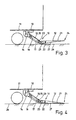
- the tail lift 10 shown here is mounted on the rear side of a vehicle body 11 of a partially illustrated vehicle.
- the tail lift 10 has a flat loading platform 12, which is articulated via two Parallelogrammlenkercrue 13 and pivotally mounted on a rigid cross member 14 of the vehicle body 11.
- Each Parallelogrammlenkercru 13 has two links, of which in Figs. 1 to 4, an upper arm 15 of the front Parallelogrammlenkerpoves 13 can be seen.
- Each pair of parallelogram links 13 are associated with two pressure medium cylinders 16 and 17, of which the (upper) pressure medium cylinder 16 serves for pivoting the loading platform 12, while the lower pressure medium cylinder 17 is provided for raising and lowering the loading platform 12.
- pressure medium cylinders 16 and 17 can be supplied with a pressure medium, in particular hydraulic oil, from a pressure medium system.
- This pressure medium system preferably has a pressure medium pump which can be driven by an electric motor.
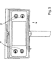
- a control panel 18 is provided, which in the embodiment shown (FIG. 5) has four operating switches 19 and 20, which are designed here as rotary switches.
- the control switches 19 and 20 may also be pressure switches or the like. Two control switches each perform the same function. They must be operated together due to appropriate accident prevention regulations to bring about the desired function, namely the pivoting, lifting or lowering of the loading platform 12.
- control switches 19 and 20 By means of the control switches 19 and 20, the hydraulic system is to be actuated such that the pressure medium cylinder 16 for pivoting the loading platform 12 on or extends or the pressure cylinder 17 for raising or lowering the loading platform 12 or extend. Additional control switches, namely foot switches, can be arranged on the upper side 21 of the loading platform 12.
- the tail lift 10 has a sensor 22 on the loading platform 12 and a further sensor 23 on a handlebar of the In the embodiment shown here, the upper link 15 of the front Parallelogrammlenker lies 13 via a sensor 23.
- the sensors 22 and 23 are preferably equally trained micro-sensors, due to their small size at any point of the upper arm 15 or the loading platform 12 are attachable.
- the sensors 22, 23 provide an electrical signal that is tilt dependent. If the inclination of the upper link 15 and / or the loading platform 12 changes, the inclination of the associated sensors 22 and / or 23 simultaneously changes, as a result of which the signal thereof changes.
- the electrical signal continuously emitted by the sensors 22 and / or 23, which preferably changes proportionally with the inclination, thus allows conclusions to be drawn about the respective inclination of the loading platform 12 and / or the upper link 15.
- the sensors 22 and 23 are connected via suitable electrical lines or possibly also wirelessly connected to a circuit, not shown.
- a circuit which is preferably a microprocessor (CPU).
- CPU central processing unit
- This serves to store and evaluate the electrical signals. For example, at least one electrical signal is output, which is output by the sensor 22 and / or 23 at the moment to the controller in which certain control switches 19 or 20 are actuated or released.
- the or each signal thus stored is used by the circuit as a setpoint for restarting the position of the loading platform 12 corresponding to the stored value.
- the loading platform 12 then automatically pivots to a position that was previously approached and stored.
- the sensor 23 on the upper arm 15 may be formed as a two-point sensor. This does not provide continuously to each pivot position associated measured values; Rather, only a signal when reaching a predeterminable position of the loading platform 12, in particular a fully lowered position of the same.
- the loading platform 12 By actuating the two control switches 19, the loading platform 12 is pivoted from the folded to the rear of the vehicle body 11 vertical position of FIG. 1 in the position of Fig. 2.
- the control switch 19 are operated for safety reasons at the same time. Where other fuses are provided, it may be sufficient to actuate only one operating switch 19 for pivoting the loading platform 12.
- the attached to the loading platform 12 sensor 22 is at the time when both control switches 19 are released or the inclination of the loading platform 12 has not changed over a certain period of time, a signal to the controller.
- This signal is an electrical signal that corresponds to the set inclination of the loading platform 12 shown in FIG. 2. This is a tilt-proportional, electrical signal that is stored in the circuit.
- the loading platform 12 After the loading platform 12 has pivoted into the position shown in FIG. 2, the loading platform 12 is lowered, for which purpose both operating switches 20 are actuated, and again for safety reasons at the same time.
- both operating switches 20 are actuated, and again for safety reasons at the same time.
- the loading platform 12 When the loading platform 12 is lowered so far that a part of the same, in particular a pivot point 25 of the vehicle body 11 facing front side of the loading platform 12 on the Parallelogrammlenkercruen 13 and the pressure cylinder 16 and 17, rests on the floor 26 (FIG the arranged on the upper arm 15 sensor 23 a constant signal to the controller. This signals the controller that the lowering is completed.
- the method of the tail lift 10 from the loading position is as follows:
- the loading platform 12 By pressing the to lift the Loading platform 12 serving control switches 20, the loading platform 12 is first pivoted, so the trailing edge 24 of the loading platform 12 lifted from the ground 26.
- this pivoting process is monitored by the controller and automatically terminated, namely, when the loading platform 12 is a pivoting position. has reached, which corresponds to the set and stored before lowering the loading platform 12 pivot position (Fig. 2).
- the stored prior to lowering of the loading platform 12 pivot position is used by the this pivot position corresponding stored signal of the sensor 22 is used by the controller as the setpoint, during the pivoting of the loading platform 12 from the position shown in FIG in the position shown in FIG. 3 is constantly compared with thereby supplied by the sensor 22 to the controller actual signals.
- the loading platform 12 has taken the inclination that has been set before lowering the loading platform 12. Consequently, the inclination of the upper side 21 of the loading platform 12 of FIG. 2 coincides with the inclination of FIG. 3.
- the circuit thereby exerts a kind of "memory effect".
- the control initiates the lifting operation while the operating switches 20 for lifting the loading platform 12 are still pressed.
- This can be interrupted by the operator at any time by releasing at least one control switch 20. If, however, both control switches 20 are actuated, the loading platform 12 moves up into the stroke end position shown in FIG. 2, the lifting drive being automatically switched off when this stroke end position is reached.
- This can be done by mechanical limit switches of a known type; but also by the sensor 23 on the upper arm 15 of the Parallelogrammlenkerpove 13.
- the sensor 23 provides an electrical signal to the circuit, which signals the circuit upon reaching a certain signal in which the upper link 15 has taken a corresponding inclination, that the loading platform has reached its stroke end position (Fig. 2).
- the loading platform 12 is swung up into the (vertical) rest position (FIG. 1) by actuating the operating switch 19.
- the inclination of the loading platform 12 should be variable, this is done by operating both for pivoting the loading platform 12 serving control switch 19. These are only operated until the loading platform 12 their desired new oblique position has reached.
- the new measured value corresponding to this new panning position is transmitted from the sensor 22 to the circuit and stored there, the previous (old) measured value being overwritten. In the following, when swinging back the loading platform 12 the new measured value corresponding pivot position (which may also lie in the horizontal) approached.
- the circuit required for the sensors 22 and 23 is used in a preferred development of the invention for monitoring tasks and for controlling additional components.
- the circuit is used to turn on and off drives, in particular electric motors or the like, for operating the tail lifts, possibly in response to signals coming from one or more sensors 22, 23.
- pressure or force sensors in particular piezoelectric sensors or strain gauges, can be provided which determine the load on the tail lift 10 and shut off its drive in the event of an overload.
- position-dependent signal delivered by the sensor 22 in order to signal that the tail lift 10 is not in the rest position. This avoids that the vehicle gets into the traffic at not fully closed tail lift 10.
- warning lights on and off of the circuit.
- the switching on of these warning lights is preferably carried out when the sensor 22 provides a specific signal to the controller, which corresponds to the folded-down position of the loading platform 12. Conversely, when the loading platform 12 is raised, the warning lights are automatically switched off again.
Landscapes
- Engineering & Computer Science (AREA)
- Transportation (AREA)
- Mechanical Engineering (AREA)
- Vehicle Step Arrangements And Article Storage (AREA)
- Auxiliary Methods And Devices For Loading And Unloading (AREA)
- Control And Other Processes For Unpacking Of Materials (AREA)
- Container Filling Or Packaging Operations (AREA)
- Supplying Of Containers To The Packaging Station (AREA)
- Load-Engaging Elements For Cranes (AREA)
- Forklifts And Lifting Vehicles (AREA)
- Jib Cranes (AREA)
Claims (10)
- Procédé pour commander un hayon élévateur (10) présentant une plate-forme de chargement (12), la plate-forme de chargement (12) étant aussi bien basculée qu'abaissée ou élevée, caractérisé en ce qu'au moins un signal électrique, qui correspond au moins à une position de basculement de la plate-forme de chargement (12) amorcée manuellement et individuellement, est mise en mémoire et cette position de basculement est réamorcée automatiquement lors d'un basculement ultérieur de la plate-forme de chargement (12), la position de basculement de la plate-forme de chargement (12) étant mise en mémoire avant l'abaissement de celle-ci
- Procédé selon la revendication 1, caractérisé en ce que la position de basculement mise en mémoire est prise automatiquement lors du basculement de retour de la plate-forme de chargement (12).
- Procédé selon la revendication 1 ou 2, caractérisé en ce qu'une position terminale est mise en mémoire lors du basculement de la plate-forme de chargement (12) d'une position de repos relevée dans une position rabattue et, après un basculement ultérieur renouvelé de la plate-forme de chargement (12), la position mise en mémoire est automatiquement réamorcée lors du basculement de retour de la plate-forme de chargement (12).
- Procédé selon une ou plusieurs des revendications 1 à 3 caractérisé en ce qu'après l'abaissement complet de la plate-forme de chargement (12) et un basculement de celle-ci pour l'adaptation à l'allure d'un sol sur lequel la plate-forme de chargement (12) s'appuie, un basculement de retour de la plate-forme de chargement (12) dans la position précédemment mise en mémoire a lieu.
- Procédé selon une ou plusieurs des revendications 1 à 4, caractérisé en ce que lors du déclenchement du processus de levage, avant l'élévation de la plate-forme de chargement (12), un basculement de celle-ci dans la position de basculement mise en mémoire a lieu, en particulier pendant l'actionnement d'au moins un commutateur de commande (20) pour le levage de la plate-forme de chargement (12).
- Procédé selon une ou plusieurs des revendications 1 à 5, caractérisé en ce qu'avec la mise en mémoire de la position de basculement de la plate-forme de chargement (12), au moins une fonction supplémentaire est déclenchée et/ou stoppée, en particulier des fonctions supplémentaires sont assurées, de préférence commandées, par une commande pour mettre en mémoire et prendre la position de basculement de la plate-forme de chargement mise en mémoire.
- Hayon élévateur pour véhicule comprenant une plate-forme de chargement, des bras oscillants pour monter la plate-forme de chargement sur le véhicule et un organe d'actionnement pour le basculement, l'élévation et l'abaissement de la plate-forme de chargement, caractérisé en ce qu'au moins un capteur est disposé au moins sur la plate-forme de chargement (12) ou un bras oscillant (15) pour l'émission d'un signal électrique changeant continuellement lors du basculement de la plate-forme de chargement, lequel correspond à la position de basculement du moment de la plate-forme de chargement (12) et en ce qu'une commande est prévue, laquelle met en mémoire le signal provenant du capteur (22, 23) concerné pour une position de basculement déterminée de la plate-forme de chargement (12) et ramène par la suite la plate-forme de chargement (12) dans la position de basculement mise en mémoire.
- Hayon élévateur selon la revendication 7, caractérisé en ce qu'au moins un capteur (22, 23) est chaque fois disposé sur au moins un bras oscillant (15) et sur la plate-forme de chargement (12).
- Hayon élévateur selon la revendication 7 ou 8, caractérisé en ce que le capteur concerné (22 et / ou 23) est configuré comme un microcapteur.
- Hayon élévateur selon une ou plusieurs des revendications 7 à 9 , caractérisé en ce que la commande est configurée pour comparer le signal électrique mis en mémoire avec un signal provenant du capteur (22) et correspondant à la position de basculement du moment de la plate-forme de chargement (12), cette comparaison étant effectuée de telle manière qu'en cas de coïncidence des signaux, la commande arrête le basculement de la plate-forme de chargement (12).
Applications Claiming Priority (2)
| Application Number | Priority Date | Filing Date | Title |
|---|---|---|---|
| DE19541791 | 1995-11-09 | ||
| DE19541791A DE19541791A1 (de) | 1995-11-09 | 1995-11-09 | Hubladebühne und Verfahren zur Steuerung derselben |
Publications (3)
| Publication Number | Publication Date |
|---|---|
| EP0773136A1 EP0773136A1 (fr) | 1997-05-14 |
| EP0773136B1 EP0773136B1 (fr) | 2001-12-05 |
| EP0773136B2 true EP0773136B2 (fr) | 2007-11-14 |
Family
ID=7777027
Family Applications (1)
| Application Number | Title | Priority Date | Filing Date |
|---|---|---|---|
| EP96116394A Expired - Lifetime EP0773136B2 (fr) | 1995-11-09 | 1996-10-12 | Plate-forme de hayon et procédé pour sa commande |
Country Status (4)
| Country | Link |
|---|---|
| EP (1) | EP0773136B2 (fr) |
| AT (1) | ATE210032T1 (fr) |
| DE (2) | DE19541791A1 (fr) |
| DK (1) | DK0773136T3 (fr) |
Cited By (1)
| Publication number | Priority date | Publication date | Assignee | Title |
|---|---|---|---|---|
| TWI728679B (zh) * | 2020-02-04 | 2021-05-21 | 國立虎尾科技大學 | 曲柄搖臂驅動之貨車尾門升降裝置 |
Families Citing this family (9)
| Publication number | Priority date | Publication date | Assignee | Title |
|---|---|---|---|---|
| DE50002661D1 (de) * | 2000-09-21 | 2003-07-31 | Gerd Baer | Steuerung für eine Hubladebühne |
| DE10254035B4 (de) * | 2002-11-20 | 2004-12-09 | Kurt Scharfenberger | Lastkraftwagen |
| DE20317896U1 (de) * | 2003-11-19 | 2004-04-01 | Mbb Liftsystems Ag | Bedieneinrichtung für insbesondere eine Hubladebühne |
| DE102005021352A1 (de) | 2005-05-04 | 2006-11-16 | Mbb Liftsystems Ag | Hubladebühne und Verfahren zum Ein- und Ausfahren derselben |
| DE102006062231B4 (de) * | 2006-12-22 | 2020-02-27 | Wüllhorst GmbH & Co. Kommanditgesellschaft | Ladebordwand für ein Transportfahrzeug |
| DE102011011085A1 (de) * | 2011-02-11 | 2012-08-16 | Mbb Palfinger Gmbh | Verfahren zum Steuern einer Hubladebühne |
| DE102011100643A1 (de) * | 2011-05-05 | 2012-11-08 | Bär Management- und Beteiligungsgesellschaft mbH | Verfahren zum Betreiben einer Überwachungsanordnung für eine Hubladebühne, Überwachungsanordnung und Hubladebühne |
| EP2620322B1 (fr) * | 2012-01-24 | 2016-04-13 | Bär Management- und Beteiligungsgesellschaft mbH | Procédé destiné au fonctionnement d'une plateforme de chargement |
| DE102018003577A1 (de) * | 2018-05-04 | 2019-11-07 | Palfinger Tail Lifts Gmbh | Bedieneinrichtung für eine Hubladebühne |
Family Cites Families (8)
| Publication number | Priority date | Publication date | Assignee | Title |
|---|---|---|---|---|
| AT318408B (de) * | 1971-11-15 | 1974-10-25 | Weber Walter Ing | Ladeplattform für Lastkraftwagen |
| DE2654286A1 (de) * | 1976-11-30 | 1978-06-01 | Dautel Emil Kipperbau | Ladevorrichtung fuer lastfahrzeugaufbauten |
| DE2824889A1 (de) * | 1978-06-07 | 1979-12-20 | Dautel Emil Kipperbau | Ladevorrichtung an lastfahrzeugaufbauten |
| DE3345589A1 (de) * | 1983-12-16 | 1985-06-27 | Emil Dautel GmbH, 7105 Leingarten | Hubladebuehne mit ansteuerschaltung |
| AT387208B (de) * | 1986-04-04 | 1988-12-27 | Voest Alpine Ag | Transportfahrzeug sowie einrichtung zum ueberwachen der kippsicherheit der last auf einem derartigen transportfahrzeug |
| DE4012604C1 (en) * | 1990-04-20 | 1991-07-25 | Binz Gmbh & Co, 7073 Lorch, De | Stretcher support for ambulance - has actuator adjusted using scanner to set load level |
| DE4108551A1 (de) * | 1991-03-15 | 1992-11-05 | Mbb Foerder & Hebesysteme | Vorrichtung zum steuern von hubvorrichtungen |
| DE29508800U1 (de) * | 1995-05-27 | 1995-08-17 | Lödige Fördertechnik GmbH, 34414 Warburg | Maschinelle Handhabungsvorrichtung mit einer Gabel |
-
1995
- 1995-11-09 DE DE19541791A patent/DE19541791A1/de not_active Withdrawn
-
1996
- 1996-10-12 DK DK96116394T patent/DK0773136T3/da active
- 1996-10-12 DE DE59608363T patent/DE59608363D1/de not_active Expired - Lifetime
- 1996-10-12 EP EP96116394A patent/EP0773136B2/fr not_active Expired - Lifetime
- 1996-10-12 AT AT96116394T patent/ATE210032T1/de active
Cited By (1)
| Publication number | Priority date | Publication date | Assignee | Title |
|---|---|---|---|---|
| TWI728679B (zh) * | 2020-02-04 | 2021-05-21 | 國立虎尾科技大學 | 曲柄搖臂驅動之貨車尾門升降裝置 |
Also Published As
| Publication number | Publication date |
|---|---|
| EP0773136A1 (fr) | 1997-05-14 |
| EP0773136B1 (fr) | 2001-12-05 |
| DE19541791A1 (de) | 1997-05-15 |
| DK0773136T3 (da) | 2002-03-04 |
| DE59608363D1 (de) | 2002-01-17 |
| ATE210032T1 (de) | 2001-12-15 |
Similar Documents
| Publication | Publication Date | Title |
|---|---|---|
| DE19747949C2 (de) | Vorrichtung zur Längeneinstellung eines Oberlenkers einer Anbaueinrichtung eines Traktors | |
| DE69604315T2 (de) | Höhenregelungssystem für Kraftfahrzeuge | |
| EP3091125B1 (fr) | Engin équipé d'un dispositif de levage pour un processus de chargement et procédé de réglage d'un hayon | |
| EP0773136B2 (fr) | Plate-forme de hayon et procédé pour sa commande | |
| DE3910660A1 (de) | Sicherheitsschaltanordnung fuer hubkipp- oder kippvorrichtungen | |
| DE69708427T2 (de) | Verbessertes Höhenregelungssystem für Kraftfahrzeuge | |
| DE19520166C2 (de) | Maststeuerung für nicht-schwingungsfreie Vielgelenkgeräte, insbesondere für vielgliedrige Betonpumpen-Verteilausleger | |
| WO1993009014A1 (fr) | Wagon basculant | |
| EP1762535B1 (fr) | Engin roulant du type muni d'un bras et procédé pour celui-ci | |
| EP1250832A1 (fr) | Dispositif pour contrôler la position d'un dispositif de déchargement d'une machine agricole de récolte | |
| DE2240552A1 (de) | Vorrichtung zum handhaben von lasten | |
| DE2950852C2 (fr) | ||
| DE1941940C3 (de) | Fahrzeug mit Hebevorrichtung für großvolumige Kästen, vorzugsweise aus Beton, mit Ausnehmungen im Boden für teleskopisch längenveränderliche Beine der Hebevorrichtung | |
| EP2832585B1 (fr) | Hayon élévateur et son procédé de commande | |
| EP1179466B1 (fr) | Chariot de manutention avec un dispositif de ramassage de charges | |
| EP3266732B1 (fr) | Niveleur de quai à lèvre télescopique ainsi que procédé de raccordement d'une soute d'un véhicule de transport à un niveau de quai à lèvre télescopique | |
| DE4331613C2 (de) | Kurzkupplungssystem | |
| DE102006062231B4 (de) | Ladebordwand für ein Transportfahrzeug | |
| EP4190973A1 (fr) | Machine à fraiser le sol, en particulier machine à fraiser ou à recycler, et procédé de fonctionnement d'une machine à fraiser le sol | |
| EP2499022B1 (fr) | Hayon élévateur et procédé de faire fonctionner la meme | |
| EP3456584B1 (fr) | Véhicule de transport de charges et son procédé de fonctionnement | |
| DE2357839C3 (de) | Hebebühne | |
| EP1719661A1 (fr) | Plate-forme de hayon et procédé pour faire sortir et rentrer la même | |
| DE1634804B2 (de) | Hydraulische steuervorrichtung fuer die antriebsmotoren eines loeffelbaggers | |
| EP4613941A1 (fr) | Véhicule de chargement avec fonction de ramassage automatique et procédé associé |
Legal Events
| Date | Code | Title | Description |
|---|---|---|---|
| PUAI | Public reference made under article 153(3) epc to a published international application that has entered the european phase |
Free format text: ORIGINAL CODE: 0009012 |
|
| AK | Designated contracting states |
Kind code of ref document: A1 Designated state(s): AT BE CH DE DK FR GB IT LI NL |
|
| 17P | Request for examination filed |
Effective date: 19971103 |
|
| RAP1 | Party data changed (applicant data changed or rights of an application transferred) |
Owner name: MBB LIFTSYSTEMS AG |
|
| 17Q | First examination report despatched |
Effective date: 19990803 |
|
| GRAG | Despatch of communication of intention to grant |
Free format text: ORIGINAL CODE: EPIDOS AGRA |
|
| GRAG | Despatch of communication of intention to grant |
Free format text: ORIGINAL CODE: EPIDOS AGRA |
|
| GRAH | Despatch of communication of intention to grant a patent |
Free format text: ORIGINAL CODE: EPIDOS IGRA |
|
| GRAH | Despatch of communication of intention to grant a patent |
Free format text: ORIGINAL CODE: EPIDOS IGRA |
|
| GRAA | (expected) grant |
Free format text: ORIGINAL CODE: 0009210 |
|
| AK | Designated contracting states |
Kind code of ref document: B1 Designated state(s): AT BE CH DE DK FR GB IT LI NL |
|
| PG25 | Lapsed in a contracting state [announced via postgrant information from national office to epo] |
Ref country code: IT Free format text: LAPSE BECAUSE OF FAILURE TO SUBMIT A TRANSLATION OF THE DESCRIPTION OR TO PAY THE FEE WITHIN THE PRE;WARNING: LAPSES OF ITALIAN PATENTS WITH EFFECTIVE DATE BEFORE 2007 MAY HAVE OCCURRED AT ANY TIME BEFORE 2007. THE CORRECT EFFECTIVE DATE MAY BE DIFFERENT FROM THE ONE RECORDED.SCRIBED TIME-LIMIT Effective date: 20011205 |
|
| REF | Corresponds to: |
Ref document number: 210032 Country of ref document: AT Date of ref document: 20011215 Kind code of ref document: T |
|
| REG | Reference to a national code |
Ref country code: CH Ref legal event code: NV Representative=s name: DIPL.-ING. ETH H. R. WERFFELI PATENTANWALT Ref country code: CH Ref legal event code: EP |
|
| REG | Reference to a national code |
Ref country code: GB Ref legal event code: IF02 |
|
| GBT | Gb: translation of ep patent filed (gb section 77(6)(a)/1977) |
Effective date: 20011206 |
|
| REF | Corresponds to: |
Ref document number: 59608363 Country of ref document: DE Date of ref document: 20020117 |
|
| REG | Reference to a national code |
Ref country code: DK Ref legal event code: T3 |
|
| ET | Fr: translation filed | ||
| PLBQ | Unpublished change to opponent data |
Free format text: ORIGINAL CODE: EPIDOS OPPO |
|
| PLBI | Opposition filed |
Free format text: ORIGINAL CODE: 0009260 |
|
| PLBF | Reply of patent proprietor to notice(s) of opposition |
Free format text: ORIGINAL CODE: EPIDOS OBSO |
|
| 26 | Opposition filed |
Opponent name: DAUTEL GMBH Effective date: 20020905 |
|
| NLR1 | Nl: opposition has been filed with the epo |
Opponent name: DAUTEL GMBH |
|
| PLBF | Reply of patent proprietor to notice(s) of opposition |
Free format text: ORIGINAL CODE: EPIDOS OBSO |
|
| PLBF | Reply of patent proprietor to notice(s) of opposition |
Free format text: ORIGINAL CODE: EPIDOS OBSO |
|
| PGFP | Annual fee paid to national office [announced via postgrant information from national office to epo] |
Ref country code: DK Payment date: 20031015 Year of fee payment: 8 |
|
| PGFP | Annual fee paid to national office [announced via postgrant information from national office to epo] |
Ref country code: CH Payment date: 20031017 Year of fee payment: 8 |
|
| PG25 | Lapsed in a contracting state [announced via postgrant information from national office to epo] |
Ref country code: LI Free format text: LAPSE BECAUSE OF NON-PAYMENT OF DUE FEES Effective date: 20041031 Ref country code: CH Free format text: LAPSE BECAUSE OF NON-PAYMENT OF DUE FEES Effective date: 20041031 |
|
| PG25 | Lapsed in a contracting state [announced via postgrant information from national office to epo] |
Ref country code: DK Free format text: LAPSE BECAUSE OF NON-PAYMENT OF DUE FEES Effective date: 20041101 |
|
| REG | Reference to a national code |
Ref country code: DK Ref legal event code: EBP |
|
| REG | Reference to a national code |
Ref country code: CH Ref legal event code: PL |
|
| PUAH | Patent maintained in amended form |
Free format text: ORIGINAL CODE: 0009272 |
|
| STAA | Information on the status of an ep patent application or granted ep patent |
Free format text: STATUS: PATENT MAINTAINED AS AMENDED |
|
| 27A | Patent maintained in amended form |
Effective date: 20071114 |
|
| AK | Designated contracting states |
Kind code of ref document: B2 Designated state(s): AT BE CH DE DK FR GB IT LI NL |
|
| NLR2 | Nl: decision of opposition |
Effective date: 20071114 |
|
| GBTA | Gb: translation of amended ep patent filed (gb section 77(6)(b)/1977) | ||
| NLR3 | Nl: receipt of modified translations in the netherlands language after an opposition procedure | ||
| ET3 | Fr: translation filed ** decision concerning opposition | ||
| PGFP | Annual fee paid to national office [announced via postgrant information from national office to epo] |
Ref country code: NL Payment date: 20121010 Year of fee payment: 17 |
|
| PGFP | Annual fee paid to national office [announced via postgrant information from national office to epo] |
Ref country code: FR Payment date: 20131023 Year of fee payment: 18 Ref country code: DE Payment date: 20131029 Year of fee payment: 18 Ref country code: GB Payment date: 20131023 Year of fee payment: 18 Ref country code: AT Payment date: 20131028 Year of fee payment: 18 Ref country code: BE Payment date: 20131023 Year of fee payment: 18 |
|
| REG | Reference to a national code |
Ref country code: NL Ref legal event code: V1 Effective date: 20140501 |
|
| PG25 | Lapsed in a contracting state [announced via postgrant information from national office to epo] |
Ref country code: NL Free format text: LAPSE BECAUSE OF NON-PAYMENT OF DUE FEES Effective date: 20140501 |
|
| REG | Reference to a national code |
Ref country code: DE Ref legal event code: R119 Ref document number: 59608363 Country of ref document: DE |
|
| REG | Reference to a national code |
Ref country code: AT Ref legal event code: MM01 Ref document number: 210032 Country of ref document: AT Kind code of ref document: T Effective date: 20141012 |
|
| GBPC | Gb: european patent ceased through non-payment of renewal fee |
Effective date: 20141012 |
|
| PG25 | Lapsed in a contracting state [announced via postgrant information from national office to epo] |
Ref country code: BE Free format text: LAPSE BECAUSE OF NON-PAYMENT OF DUE FEES Effective date: 20141031 |
|
| PG25 | Lapsed in a contracting state [announced via postgrant information from national office to epo] |
Ref country code: DE Free format text: LAPSE BECAUSE OF NON-PAYMENT OF DUE FEES Effective date: 20150501 Ref country code: GB Free format text: LAPSE BECAUSE OF NON-PAYMENT OF DUE FEES Effective date: 20141012 |
|
| REG | Reference to a national code |
Ref country code: FR Ref legal event code: ST Effective date: 20150630 |
|
| PG25 | Lapsed in a contracting state [announced via postgrant information from national office to epo] |
Ref country code: FR Free format text: LAPSE BECAUSE OF NON-PAYMENT OF DUE FEES Effective date: 20141031 Ref country code: AT Free format text: LAPSE BECAUSE OF NON-PAYMENT OF DUE FEES Effective date: 20141012 |