EP3050163B1 - Method for establishing an electrically conductive connection between an electrical line and an electrically conductive component - Google Patents
Method for establishing an electrically conductive connection between an electrical line and an electrically conductive component Download PDFInfo
- Publication number
- EP3050163B1 EP3050163B1 EP14771901.7A EP14771901A EP3050163B1 EP 3050163 B1 EP3050163 B1 EP 3050163B1 EP 14771901 A EP14771901 A EP 14771901A EP 3050163 B1 EP3050163 B1 EP 3050163B1
- Authority
- EP
- European Patent Office
- Prior art keywords
- individual conductors
- crimping element
- crimping
- electrically conductive
- conductive component
- Prior art date
- Legal status (The legal status is an assumption and is not a legal conclusion. Google has not performed a legal analysis and makes no representation as to the accuracy of the status listed.)
- Active
Links
- 238000000034 method Methods 0.000 title claims description 79
- 238000002788 crimping Methods 0.000 claims description 246
- 239000004020 conductor Substances 0.000 claims description 151
- 238000003466 welding Methods 0.000 claims description 84
- 239000000463 material Substances 0.000 claims description 36
- 239000007769 metal material Substances 0.000 claims description 5
- 238000005452 bending Methods 0.000 claims description 2
- 239000010949 copper Substances 0.000 description 14
- RYGMFSIKBFXOCR-UHFFFAOYSA-N Copper Chemical compound [Cu] RYGMFSIKBFXOCR-UHFFFAOYSA-N 0.000 description 13
- 229910052802 copper Inorganic materials 0.000 description 13
- 229910052782 aluminium Inorganic materials 0.000 description 11
- XAGFODPZIPBFFR-UHFFFAOYSA-N aluminium Chemical compound [Al] XAGFODPZIPBFFR-UHFFFAOYSA-N 0.000 description 11
- 230000007797 corrosion Effects 0.000 description 9
- 238000005260 corrosion Methods 0.000 description 9
- 238000004519 manufacturing process Methods 0.000 description 6
- 238000003825 pressing Methods 0.000 description 6
- 239000007858 starting material Substances 0.000 description 6
- 229910000838 Al alloy Inorganic materials 0.000 description 5
- 238000005056 compaction Methods 0.000 description 5
- 229910000881 Cu alloy Inorganic materials 0.000 description 4
- PXHVJJICTQNCMI-UHFFFAOYSA-N Nickel Chemical compound [Ni] PXHVJJICTQNCMI-UHFFFAOYSA-N 0.000 description 4
- 230000001154 acute effect Effects 0.000 description 3
- 239000011248 coating agent Substances 0.000 description 3
- 238000000576 coating method Methods 0.000 description 3
- 230000002349 favourable effect Effects 0.000 description 3
- 229910052751 metal Inorganic materials 0.000 description 3
- 239000002184 metal Substances 0.000 description 3
- 239000002994 raw material Substances 0.000 description 3
- FAPWRFPIFSIZLT-UHFFFAOYSA-M Sodium chloride Chemical compound [Na+].[Cl-] FAPWRFPIFSIZLT-UHFFFAOYSA-M 0.000 description 2
- 230000000295 complement effect Effects 0.000 description 2
- 230000005284 excitation Effects 0.000 description 2
- 229910052759 nickel Inorganic materials 0.000 description 2
- 238000002360 preparation method Methods 0.000 description 2
- 229910052709 silver Inorganic materials 0.000 description 2
- 239000004332 silver Substances 0.000 description 2
- HBBGRARXTFLTSG-UHFFFAOYSA-N Lithium ion Chemical compound [Li+] HBBGRARXTFLTSG-UHFFFAOYSA-N 0.000 description 1
- 230000009286 beneficial effect Effects 0.000 description 1
- 230000006835 compression Effects 0.000 description 1
- 238000007906 compression Methods 0.000 description 1
- 230000007423 decrease Effects 0.000 description 1
- 238000009826 distribution Methods 0.000 description 1
- 229910001416 lithium ion Inorganic materials 0.000 description 1
- 239000011780 sodium chloride Substances 0.000 description 1
- 239000011343 solid material Substances 0.000 description 1
- 238000002604 ultrasonography Methods 0.000 description 1
Images


Classifications
-
- H—ELECTRICITY
- H01—ELECTRIC ELEMENTS
- H01R—ELECTRICALLY-CONDUCTIVE CONNECTIONS; STRUCTURAL ASSOCIATIONS OF A PLURALITY OF MUTUALLY-INSULATED ELECTRICAL CONNECTING ELEMENTS; COUPLING DEVICES; CURRENT COLLECTORS
- H01R43/00—Apparatus or processes specially adapted for manufacturing, assembling, maintaining, or repairing of line connectors or current collectors or for joining electric conductors
- H01R43/02—Apparatus or processes specially adapted for manufacturing, assembling, maintaining, or repairing of line connectors or current collectors or for joining electric conductors for soldered or welded connections
- H01R43/0207—Ultrasonic-, H.F.-, cold- or impact welding
-
- B—PERFORMING OPERATIONS; TRANSPORTING
- B23—MACHINE TOOLS; METAL-WORKING NOT OTHERWISE PROVIDED FOR
- B23K—SOLDERING OR UNSOLDERING; WELDING; CLADDING OR PLATING BY SOLDERING OR WELDING; CUTTING BY APPLYING HEAT LOCALLY, e.g. FLAME CUTTING; WORKING BY LASER BEAM
- B23K20/00—Non-electric welding by applying impact or other pressure, with or without the application of heat, e.g. cladding or plating
- B23K20/10—Non-electric welding by applying impact or other pressure, with or without the application of heat, e.g. cladding or plating making use of vibrations, e.g. ultrasonic welding
-
- H—ELECTRICITY
- H01—ELECTRIC ELEMENTS
- H01R—ELECTRICALLY-CONDUCTIVE CONNECTIONS; STRUCTURAL ASSOCIATIONS OF A PLURALITY OF MUTUALLY-INSULATED ELECTRICAL CONNECTING ELEMENTS; COUPLING DEVICES; CURRENT COLLECTORS
- H01R4/00—Electrically-conductive connections between two or more conductive members in direct contact, i.e. touching one another; Means for effecting or maintaining such contact; Electrically-conductive connections having two or more spaced connecting locations for conductors and using contact members penetrating insulation
- H01R4/10—Electrically-conductive connections between two or more conductive members in direct contact, i.e. touching one another; Means for effecting or maintaining such contact; Electrically-conductive connections having two or more spaced connecting locations for conductors and using contact members penetrating insulation effected solely by twisting, wrapping, bending, crimping, or other permanent deformation
- H01R4/18—Electrically-conductive connections between two or more conductive members in direct contact, i.e. touching one another; Means for effecting or maintaining such contact; Electrically-conductive connections having two or more spaced connecting locations for conductors and using contact members penetrating insulation effected solely by twisting, wrapping, bending, crimping, or other permanent deformation by crimping
- H01R4/187—Electrically-conductive connections between two or more conductive members in direct contact, i.e. touching one another; Means for effecting or maintaining such contact; Electrically-conductive connections having two or more spaced connecting locations for conductors and using contact members penetrating insulation effected solely by twisting, wrapping, bending, crimping, or other permanent deformation by crimping combined with soldering or welding
-
- H—ELECTRICITY
- H01—ELECTRIC ELEMENTS
- H01R—ELECTRICALLY-CONDUCTIVE CONNECTIONS; STRUCTURAL ASSOCIATIONS OF A PLURALITY OF MUTUALLY-INSULATED ELECTRICAL CONNECTING ELEMENTS; COUPLING DEVICES; CURRENT COLLECTORS
- H01R4/00—Electrically-conductive connections between two or more conductive members in direct contact, i.e. touching one another; Means for effecting or maintaining such contact; Electrically-conductive connections having two or more spaced connecting locations for conductors and using contact members penetrating insulation
- H01R4/58—Electrically-conductive connections between two or more conductive members in direct contact, i.e. touching one another; Means for effecting or maintaining such contact; Electrically-conductive connections having two or more spaced connecting locations for conductors and using contact members penetrating insulation characterised by the form or material of the contacting members
- H01R4/62—Connections between conductors of different materials; Connections between or with aluminium or steel-core aluminium conductors
- H01R4/625—Soldered or welded connections
-
- H—ELECTRICITY
- H01—ELECTRIC ELEMENTS
- H01R—ELECTRICALLY-CONDUCTIVE CONNECTIONS; STRUCTURAL ASSOCIATIONS OF A PLURALITY OF MUTUALLY-INSULATED ELECTRICAL CONNECTING ELEMENTS; COUPLING DEVICES; CURRENT COLLECTORS
- H01R43/00—Apparatus or processes specially adapted for manufacturing, assembling, maintaining, or repairing of line connectors or current collectors or for joining electric conductors
- H01R43/04—Apparatus or processes specially adapted for manufacturing, assembling, maintaining, or repairing of line connectors or current collectors or for joining electric conductors for forming connections by deformation, e.g. crimping tool
- H01R43/048—Crimping apparatus or processes
- H01R43/0484—Crimping apparatus or processes for eyelet contact members
-
- B—PERFORMING OPERATIONS; TRANSPORTING
- B23—MACHINE TOOLS; METAL-WORKING NOT OTHERWISE PROVIDED FOR
- B23K—SOLDERING OR UNSOLDERING; WELDING; CLADDING OR PLATING BY SOLDERING OR WELDING; CUTTING BY APPLYING HEAT LOCALLY, e.g. FLAME CUTTING; WORKING BY LASER BEAM
- B23K2101/00—Articles made by soldering, welding or cutting
- B23K2101/36—Electric or electronic devices
- B23K2101/38—Conductors
-
- H—ELECTRICITY
- H01—ELECTRIC ELEMENTS
- H01R—ELECTRICALLY-CONDUCTIVE CONNECTIONS; STRUCTURAL ASSOCIATIONS OF A PLURALITY OF MUTUALLY-INSULATED ELECTRICAL CONNECTING ELEMENTS; COUPLING DEVICES; CURRENT COLLECTORS
- H01R4/00—Electrically-conductive connections between two or more conductive members in direct contact, i.e. touching one another; Means for effecting or maintaining such contact; Electrically-conductive connections having two or more spaced connecting locations for conductors and using contact members penetrating insulation
- H01R4/10—Electrically-conductive connections between two or more conductive members in direct contact, i.e. touching one another; Means for effecting or maintaining such contact; Electrically-conductive connections having two or more spaced connecting locations for conductors and using contact members penetrating insulation effected solely by twisting, wrapping, bending, crimping, or other permanent deformation
- H01R4/18—Electrically-conductive connections between two or more conductive members in direct contact, i.e. touching one another; Means for effecting or maintaining such contact; Electrically-conductive connections having two or more spaced connecting locations for conductors and using contact members penetrating insulation effected solely by twisting, wrapping, bending, crimping, or other permanent deformation by crimping
- H01R4/183—Electrically-conductive connections between two or more conductive members in direct contact, i.e. touching one another; Means for effecting or maintaining such contact; Electrically-conductive connections having two or more spaced connecting locations for conductors and using contact members penetrating insulation effected solely by twisting, wrapping, bending, crimping, or other permanent deformation by crimping for cylindrical elongated bodies, e.g. cables having circular cross-section
- H01R4/184—Electrically-conductive connections between two or more conductive members in direct contact, i.e. touching one another; Means for effecting or maintaining such contact; Electrically-conductive connections having two or more spaced connecting locations for conductors and using contact members penetrating insulation effected solely by twisting, wrapping, bending, crimping, or other permanent deformation by crimping for cylindrical elongated bodies, e.g. cables having circular cross-section comprising a U-shaped wire-receiving portion
Definitions
- the present invention relates to a method for producing an electrically conductive connection between an electrical line, which comprises a plurality of individual conductors, and an electrically conductive component.
- connection between the aluminum strands and the copper sword corrodes under the influence of atmospheric humidity and / or NaCl solution, so that the tensile strength of the connection drops sharply due to corrosion.
- the U.S. 3,717,842 A discloses a method according to the preamble of claim 1.
- the present invention is based on the object of creating a method for producing an electrically conductive connection between an electrical line comprising several individual conductors and an electrically conductive component which can be carried out easily and preferably without the use of additional corrosion protection and yet becomes corrosion-resistant Connection between the individual conductors of the electrical line and the electrically conductive component leads.
- the present invention is based on the concept of combining mechanical fixation of the individual conductors by crimping with improved compacting of the individual conductors during crimping and during the ultrasonic welding process.
- the individual conductors are compacted to such an extent that the entirety of the individual conductors comes close to being a solid material.
- the corrosion does not find enough attack surface on the compacted individual conductors to damage the connection point decisively.
- the additional mechanical securing and / or fixing of the individual conductors by means of the crimping additionally prevents the individual conductors from being able to detach from the connection with the electrically conductive component, even if a corrosive event nevertheless occurs.
- the individual conductors are preferably completely enclosed by the crimping element before the ultrasonic welding process.
- the crimping which is preferably carried out before the ultrasonic welding process, brings the individual conductors into a defined shape, which leads to greater process reliability in the subsequent ultrasonic welding process.
- connection between the electrical line and the electrically conductive component has a higher strength and not through a loosening of the ultrasonic welded connection, but at best through a material failure of the individual conductors is interrupted. It is more likely that the individual conductors behind the weld tear off before the connection loosens at the weld point itself.
- the initial values for the tensile strength of the connection between the electrical line and the electrically conductive component are already significantly higher immediately after the electrically conductive connection has been established than with known connection methods. Since the tensile strength of the connection is no longer determined by the failure of the weld, but by the material failure of the individual conductors, the process capability is significantly increased, since the individual conductors always tear at similar tensile loads.
- the individual conductors are protected by enclosing with the crimping element and welding at least a part of the individual conductors to the crimping element. Furthermore, a constriction of the individual conductors during the ultrasonic welding process is avoided, which could lead to an easier tearing of the individual conductors. In the method according to the invention, no predetermined breaking points are thus generated on the individual conductors.
- connection point produced by the method according to the invention between the electrical line and the electrically conductive component can be used without applying corrosion protection media to the connection point.
- the sonotrode is different from the crimping tool.
- the crimping process and the ultrasonic welding process are therefore preferably carried out one after the other in different tools.
- the ultrasonic welding process is preferably only started after the crimping element has been produced.
- the individual conductors are compacted both by means of the crimping tool and by means of the sonotrode of the ultrasonic welding tool.
- the space volume remaining between the individual conductors of the electrical line in the area of the crimping element thus decreases during the crimping process and is further reduced during the ultrasonic welding process.
- Good compaction of the individual conductors is achieved in particular when the welding pressure of the sonotrode is at least temporarily at least approximately 3 bar, in particular at least approximately 4 bar, for example at least approximately 5 bar.
- a welding pressure of approximately 5 bar has proven to be particularly favorable in tests.
- the welding time of the ultrasonic welding process is at least approximately 1.0 seconds, preferably at least approximately 1.5 seconds, in particular at least approximately 3 seconds.
- the welding time of the ultrasonic welding process is in particular the time that is required to open the crimping element which surrounds the individual conductors to deform a specified final height (so-called final node height) (for example to a final node height of 7.5 mm).
- the crimping element preform is a component produced separately from the electrically conductive component.
- the crimping element preform is formed in one piece with the electrically conductive component.
- the crimping element preform and / or the crimping element formed therefrom preferably have a material thickness of at least approximately 1 mm, in particular at least approximately 1.5 mm, for example at least approximately 1.8 mm.
- the crimping element preform and / or the crimping element formed therefrom can comprise a, preferably coated, copper material with a material thickness of approximately 1.8 mm.
- the crimping element preform and / or the electrically conductive component is a metallic material with a tensile strength R m of more than 250 N / mm 2 , preferably more than 300 N / mm 2 , in particular of more than 350 N / mm 2 .
- the crimping element preform and / or the electrically conductive component can comprise a copper material with a tensile strength of at least approximately 360 N / mm 2 .
- the crimping element preform and / or the electrically conductive component comprises copper, preferably as the main component.
- the main component of a material is that component which has the highest percentage by weight of the material.
- the crimping element preform and / or the electrically conductive component are formed from copper or a copper alloy.
- the crimping element preform and / or the electrically conductive component has a coating which comprises nickel and / or silver.
- the individual conductors can in principle be formed from any material that has sufficient electrical conductivity.
- the individual conductors comprise aluminum, in particular as a main component.
- the individual conductors are formed from aluminum or from an aluminum alloy.
- the crimping element preform is formed from a material which has a higher mechanical strength than the material from which at least some of the individual conductors crimped by means of the crimping element are formed. In this way, it can be achieved in particular that a sufficiently high welding energy can be introduced into the material of the individual conductors during the ultrasonic welding process.
- the material from which the crimping element preform is formed has a higher tensile strength, a higher yield point and / or a higher modulus of elasticity than the material from which at least a part of the individual conductors is formed.
- the tensile strength of the material from which the crimping element preform is formed is at least twice, in particular at least three times, the tensile strength of the material from which at least some of the individual conductors are formed.
- the yield point of the material from which the crimping element preform is formed is at least twice, in particular at least five times, particularly preferably at least ten times, the yield point of the material from which at least some of the individual conductors are formed.
- the material from which the crimping element preform is formed can be, for example, the copper material with the designation Cu R360 according to EN 13599, which has a tensile strength of 360 MPa and a yield point of 320 MPa.
- the material from which at least some of the individual conductors crimped by means of the crimping element, in particular all of the individual conductors crimped by means of the crimping element, is formed can be, for example, the aluminum material with the designation AW-AI 99.5 according to EN 573/485, which has tensile strength from 65 to 95 MPa and a yield strength of 20 MPa.
- the method according to the invention is particularly suitable for producing an electrically conductive connection between an electrical line with a relatively large line cross-section and an electrically conductive component.
- the total cross-sectional area of the individual conductors of the electrical line in the area of the crimping element, in particular after the electrically conductive connection has been made is more than 50 mm 2 , in particular more than 55 mm 2 , for example approximately 59 mm 2 .
- the sonotrode has a contact surface with a longitudinal direction, the longitudinal direction of the contact surface during the ultrasonic welding process with free edges of the crimping element at an angle of more than 45 °, preferably an angle of more than 60 °, in particular an angle of approximately 90 °.
- the electrically conductive component comprises a welding area, on which at least a part of the individual conductors of the electrical line is fixed, and a contact area, the contact area being connected to the welding area via a beveled area.
- the contact area is connected to the welding area via a fold at an angle of more than 45 °, preferably at an angle of more than 60 °, for example at an angle of approximately 90 °.
- the folded region can extend along a folded line which is directed essentially parallel to a transverse direction of the crimping element.
- the folded area extends along a folded line which is directed transversely to the transverse direction of the crimping element.
- the folding line encloses an angle of at least approximately 10 °, in particular of at least approximately 20 °, with the transverse direction of the crimping element.
- the folding line encloses an angle of at most approximately 60 °, in particular of at most approximately 45 °, with the transverse direction of the crimping element.
- the electrically conductive component to which one or more electrical lines are connected in an electrically conductive manner comprises an electrical line element which in turn comprises a plurality of individual conductors or strands.
- the crimping element encloses the individual conductors of the electrical line element in sections.
- the crimping element thus encloses both the individual conductors of the one electrical line or of the multiple electrical lines and the individual conductors of the electrical line element.
- the individual conductors of the electrical line element are formed from a material that is different from the material of the individual conductors of the one electrical line or of the multiple electrical lines.
- the individual conductors of the electrical conduction element comprise aluminum and the individual conductors of the one electrical line or of the plurality of electrical lines comprise copper.
- the contact area merges into the welding area without a bevel.
- the electrically conductive component can in particular be designed as a module connector of an electrochemical device.
- the electrochemical device can in particular be designed as an accumulator, in particular as a lithium-ion accumulator.
- the present invention further relates to an assembly which comprises an electrical line, which comprises a plurality of individual conductors, and an electrically conductive component connected to the electrical line.
- the present invention is based on the further object of designing such an assembly in such a way that it is easy to assemble and yet has a high level of corrosion resistance.
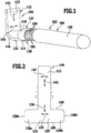
- the assembly shown designated as a whole by 100, comprises an electrical line 102 in the form of a cable 104, which comprises a plurality of stranded wires or individual conductors 106 and an electrically insulating sheath 108, as well as an electrically conductive component 110, which has a substantially plate-shaped contact area 112 and comprises a welding area 114, which are connected to one another via a bent or angled area 116, preferably in one piece.
- At least some of the individual conductors 106 of the electrical line 102 are electrically conductively connected to the electrically conductive component 110 by ultrasonic welding.
- the welding area 114 comprises a crimping element 118 which surrounds the individual conductors 106 in sections.
- the crimping element 118 encloses end sections 196 of the individual conductors 106 that are not provided with the sheathing 108.
- the crimping element 118 has a closed side 120 with a continuous, essentially flat contact surface 122 and a side lying opposite the closed side 120, hereinafter referred to as the open side 124, on which curved edge regions 126a and 126b of the crimping element 118 are opposite one another.
- free edges 128a and 128b of edge regions 126a and 126b of crimping element 118 end at a small distance from one another or touch one another (see FIG Fig. 9 until 11 , in which the electrically conductive component 110 is shown with the crimping element 118, but without the individual conductors 106 of the electrical line 102 enclosed by the crimping element 118).
- the tips 130a, 130b facing away from the closed side 120 of the crimping element 118 (see Fig. 11 )
- the edge regions 126a and 126b are spaced apart from one another in a transverse direction 132 of the crimping element 118 by an intervening depression 134.
- the base of the depression 134 is formed, for example, by the free edges 128a, 128b of the edge regions 126a and 126b of the crimping element 118, respectively.
- the transverse direction 132 of the crimping element 118 is oriented perpendicular to a longitudinal direction 136 of the crimping element 118, which runs essentially parallel to the longitudinal direction of the electrical line 102 and essentially parallel to the free edges 128a and 128b of the crimping element 118.
- the lateral free edges 128a, 128b of the crimping element 118 connect a front edge 138 to a rear edge 140 of the crimping element 118.
- the electrically conductive component 110 including the crimping element 118 is formed from an electrically conductive metallic material.
- the electrically conductive component 110 including the crimping element 118 preferably comprises a metallic material with a tensile strength R m of more than 250 N / mm 2 , in particular of more than 300 N / mm 2 , for example of more than 350 N / mm 2 .
- the electrically conductive component 110 including the crimping element 118 comprises copper, preferably as a main component.
- the main component of a component is the material that has the greatest weight proportion of the component in question.
- the electrically conductive component 110 including the crimping element 118 can comprise a copper material with a tensile strength of at least approximately 360 N / mm 2 .
- the electrically conductive component 110 including the crimping element 118 preferably has a coating.
- Such a coating can in particular comprise nickel and / or silver.
- the individual conductors 106 of the electrical line 102 can in principle be formed from any material that has sufficient electrical conductivity.
- the individual conductors 106 comprise aluminum, in particular are formed from aluminum or an aluminum alloy.
- the electrically conductive component 110 can be designed, for example, as a contact shoe of a module connector of an electrochemical device.
- the contact region 112 of the electrically conductive component 110 preferably extends in a longitudinal direction 142, which in particular is oriented essentially perpendicular to the longitudinal direction 136 of the crimping element 118 and / or essentially perpendicular to the transverse direction 132 of the crimping element 118.
- a preferably essentially flat contact surface 144 of the contact region 112 closes with the flat contact surface 122 of the crimping element 118 preferably an angle ⁇ of more than 45 °, in particular of more than 60 °, for example of approximately 90 °.
- the contact surface 144 of the contact region 112 could also be oriented essentially parallel to the contact surface 122 of the crimping element 118 and in particular be formed essentially flush with the contact surface 122 of the crimping element 118.
- a transverse direction 143 of the contact region 112 running perpendicular to the longitudinal direction 142 of the contact region 112 and parallel to the contact surface 144 of the contact region 112 is oriented essentially parallel to the transverse direction 132 of the crimping element 118.
- an intermediate area is arranged between the contact area 112 and the welding area 114 of the electrically conductive component 110, which adjoins the welding area 114 on a first edge and the contact area 112 on a second edge, the first The edge and the second edge do not run parallel to one another, but rather enclose a preferably acute angle with one another.
- the transverse direction 143 of the contact area 112 is rotated by this angle with respect to the transverse direction 132 of the crimping element 118.
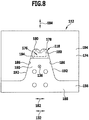
- the component preform 146 shown is cut out, for example, preferably by means of a laser, cut out or punched out from a suitable starting material, which is preferably flat, for example from a metal sheet.
- the closed side 120 and the edge areas 126a and 126b of the later crimping element 118 lie essentially in the same plane, the two edge areas 126a and 126b extending in opposite directions along the transverse direction 132 of the crimping element 118 from the closed side 120 stretch away.
- the substantially planar component preform 146 shown in FIG Figs. 3 to 5 The illustrated electrically conductive component 110 with crimping element preform 148 is generated in that the edge regions 126a and 126b and the contact region 112 are bent out of the plane of the closed side 120 in such a way that they are essentially parallel to the longitudinal direction 142 of the contact region 112 and essentially extend perpendicular to the contact surface 122 of the closed side 120.
- the edge regions 126a and 126b are connected to the closed side 120 of the crimping element preform 148 via curved regions 150a and 150b, respectively.
- the contact area 112 is already connected to the closed side 120 of the crimping element preform 148 via the beveled area 116.
- Crimping tool 152 To connect the individual conductors 106 of the electrical line 102 to the electrically conductive component 110 by crimping, for example, the in Fig. 6 Crimping tool 152 shown is used.
- This crimping tool 152 comprises an upper tool part 154, a lower tool part 156 and a positioning element 158.
- the positioning element 158 comprises a base 160 with an upper side 162 from which a rear support element 164 and two side support elements 166 extend upwards.
- the rear support element 164 has a front contact surface 168 facing the lateral support elements 166, against which the contact surface 144 of the contact area 112 of the electrically conductive component 110 can be applied, preferably essentially flat, for the crimping process.
- the lateral support elements 166 each have a lateral contact surface 170 on the mutually facing sides, on which the contact area 112 of the electrically conductive component 110 is laterally supported during the crimping process.
- the remainder of the top side 162 of the base 160 of the positioning element 158 which remains next to the rear support element 164 and the side support elements 166, forms a support surface 172 on which the electrically conductive component 110, during the crimping process, is preferably connected to part of the contact surface 122 of the crimping element preform 148 essentially flat.
- the upper tool part 154 of the crimping tool 152 comprises a, for example, essentially cuboid-shaped block 174 which, on its side facing the lower tool part 156 during the crimping process, has a recess 176 which is bordered on its upper edge by a crimp profile 178 , which is formed complementary to the open side 124 of the finished crimping element 118.
- the crimping profile 178 can thus comprise two essentially semicircular or semicircular segment-shaped profile sections 180 which are arranged next to one another in a transverse direction 182 of the crimping tool 152, which corresponds to the transverse direction 132 of the crimping element 118 to be produced.
- the upper tool part 154 is movable relative to the lower tool part 156 along a pressing direction 184 which is essentially perpendicular to the Transverse direction 182 and essentially perpendicular to the longitudinal direction 142 of the crimping element 118 to be produced.
- inclined boundary surfaces 186 of the recess 176 in the upper tool part 154 extend in the direction of the lower tool part 156.
- the inclined boundary surfaces 186 are inclined at an acute angle with respect to the pressing direction 184 of the crimping tool 152.
- the lower tool part 156 comprises a base 188, from which an anvil 190 extends in the direction of the upper tool part 154.
- the anvil has two lateral inclined boundary surfaces 192, which are preferably inclined at essentially the same acute angle with respect to the pressing direction 184 of the crimping tool 152 as the inclined boundary surfaces 186 of the recess 176 of the upper tool part 154, and one to the crimping profile 178 of the upper tool part 154 facing support surface 194, which is adapted to the shape of the contact surface 122 of the finished crimping element 118.
- the support surface 194 can therefore be designed to be essentially flat.
- the electrically conductive component 110 is connected to the in FIG Figs. 3 to 5
- the crimping element preform 148 shown is inserted into the crimping tool 152 in such a way that the contact surface 144 of the contact area 112 is in contact with the front contact surface 168 of the positioning element 158 and the contact surface 122 of the crimping element preform 148 is in contact with the contact surface 172 of the positioning element 158 and on the contact surface 194 of the lower tool part 156 is applied.
- the crimping element preform comes in 148 to lie in the space between the lower tool part 156 and the upper tool part 154, in the region of the recess 176 of the upper tool part 154 (see Fig. 7 ).
- the end sections 196 of the individual conductors 106 of the electrical line 102 that are not provided with the sheathing 108 are inserted into the crimping element preform 148 between the erected edge regions 126a and 126b (the individual conductors 106 are shown in FIGS Fig. 7 and 8th not shown).
- the upper tool part 154 which was initially at a distance from the lower tool part 156 in the pressing direction 184 (see FIG Fig. 7 ), moved along the pressing direction 184 towards the lower tool part 156, with a deformation pressure being transmitted to the crimping element preform 148 through the inclined boundary surfaces 186 of the recess 176 and the crimp profile 178.
- the crimping element preform 148 is plastically deformed in such a way that the crimping element preform 148 in Fig. 8
- the edge regions 126a, 126b of the crimping element 118 are bent around the end sections 196 of the individual conductors 106 not provided with the sheath 108 and pressed against the individual conductors 106 in such a way that the end sections enclosed by the crimping element 118 196 of the individual conductors 106 are compacted and frictionally pressed together.
- the interspace volume of the electrical line 102 remaining between the individual conductors 106 in the region of the crimping element 118 is reduced.
- the crimping tool 152 is now opened by moving the upper tool part 154 away from the lower tool part 156 relative to the lower tool part 156 along the pressing direction 184, and the assembly 100 with the electrically conductive component 110 and the electrical line 102, their individual conductors 106 through the crimping element 118 are connected to the electrically conductive component 110 is removed from the crimping tool 152 and inserted in the schematic in FIG Fig. 12 Ultrasonic welding tool 198 shown is introduced.
- the ultrasonic welding tool 198 comprises a sonotrode 200 and an anvil 202 opposite the sonotrode 200.
- the assembly 100 is placed on the anvil 202 in such a way that the contact surface 122 of the crimping element 118 comes to rest on a contact surface 204 of the anvil 202.
- the sonotrode 200 is then brought up to the assembly 100 in such a way that a contact surface 208 of the sonotrode 200 extending in a longitudinal direction 206 of the sonotrode 200 comes into contact with the open side 124 of the crimping element 118.
- the longitudinal direction 206 of the contact surface 208 of the sonotrode 200 is preferably aligned essentially parallel to the transverse direction 132 of the crimping element 118, so that the sonotrode 200 extends transversely over the recess 134 between the edge regions 126a and 126b of the crimping element 118.
- the sonotrode 200 is used to carry out the ultrasonic welding process on the assembly 100, by means of which the individual conductors 106 of the electrical line 102 are welded to one another and to the inside of the crimping element 118 on the electrically conductive component 110 by friction welding and are thus firmly bonded.
- the direction of excitation of the sonotrode 200 is preferably aligned essentially parallel to the transverse direction 132 of the crimping element 118 and / or essentially parallel to the longitudinal direction 206 of the sonotrode 200.
- the crimping element 118 and the individual conductors 106 are subjected to welding pressure by the sonotrode 200.
- the welding pressure is preferably at least temporarily at least approximately 3 bar, in particular at least approximately 4 bar, for example at least approximately 5 bar.
- a welding pressure of approximately 5 bar has proven to be particularly favorable in tests.
- the welding time during which the ultrasonic welding process takes place is preferably at least approximately 1.0 seconds, in particular at least approximately 1.5 seconds, for example at least approximately 3 seconds.
- the target variable of the ultrasonic welding process is preferably the end node height, that is to say in the present case the end height of the crimping element 118.
- the sonotrode 200 penetrates the crimping element 118 and deforms it.
- the ultrasonic welding process is continued until a predetermined final height of the crimping element 118 (For example, a final height of 7.5 mm with an initial height of 9.8 mm) is reached.
- the welding energy transmitted into assembly 100 via sonotrode 200 during the ultrasonic welding process is preferably at least approximately 3,000 Ws, in particular at least approximately 4,000 Ws, for example at least approximately 5,000 Ws, and for example at most approximately 7,000 Ws.
- the energy introduced is a resultant.
- the individual conductors 106 are further compacted in the region of the crimping element 118, that is to say the space volume of the electrical line 102 remaining between the individual conductors 106 is further reduced by the ultrasonic welding process.
- the ultrasonic welding tool 198 is opened, and the completed assembly 100, in which the individual conductors 106 of the electrical line 102 are connected to the electrically conductive component 110 both by crimping using the crimping element 118 and by ultrasonic welding, becomes the ultrasonic welding tool 198 taken.
- the illustrated second embodiment of an assembly 100 differs from that described above and in Figs. 1 to 12 illustrated embodiment in that the beveled area 116, via which the contact area 112 of the electrically conductive component 110 is connected to the welding area 114, extends along a folding line 210, which is not directed essentially parallel to the transverse direction 132 of the crimping element 118, as in the first embodiment, but transversely to it the transverse direction 132 of the crimping element 118 is directed.
- the folding line 210 and the transverse direction 132 of the crimping element 118 preferably form an angle of more than approximately 10 °, in particular of more than approximately 20 °, with one another.
- the folding line 210 and the transverse direction 132 of the crimping element 118 preferably enclose an angle of less than approximately 60 °, in particular of less than approximately 45 °, with one another.
- the angle enclosed by the folding line 210 and the transverse direction 132 of the crimping element 118 can be approximately 25 °.
- the welding area 114 of the electrically conductive component 110 is thus asymmetrical with respect to a longitudinal center plane 212 of the crimping element 118, which runs essentially perpendicular to the contact surface 122 of the crimping element 118 and essentially parallel to the longitudinal direction 136 of the crimping element 118 (see FIG Fig. 16 ).
- the procedure for producing the second embodiment of the assembly 100 is as follows: One in Fig. 14
- the component preform 146 shown is made from a suitable starting material, which is preferably flat, for example from a metal sheet, cut out, for example, preferably by means of a laser, cut out or punched out.
- the substantially planar component preform 146 shown in FIG Figures 15 and 16 The illustrated electrically conductive component 110 with crimping element preform 148 is produced in that the edge areas 126a and 126b and the contact area 112 are bent out of the plane of the closed side 120 in such a way that they are essentially parallel to the longitudinal direction 136 of the later crimping element 118 and in the Extend essentially perpendicular to the contact surface 122 of the closed side 120.
- the contact area 112 is connected to the asymmetrically formed weld area 114 via the bent area 116, which extends along the bent line 210.
- connection of the individual conductors 106 of the electrical line 102 to the electrically conductive component 110 by crimping and the connection of the individual conductors 106 of the electrical line 102 to one another and to the inside of the crimping element 118 on the electrically conductive component 110 by means of an ultrasonic welding process can be carried out like this has been described above in connection with the first embodiment of the assembly 100.
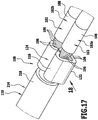
- the illustrated third embodiment of an assembly 100 differs from that in FIGS Figs. 1 to 12 illustrated first Embodiment in that not just one, but several, in particular two, electrical lines 102, namely a first electrical line 102a and a second electrical line 102b, are electrically conductively connected to the electrically conductive component 110 by means of the crimping element 118.
- the electrical lines 102a and 102b can, for example, be designed like the single electrical line 102 in the first embodiment of the assembly 100 described above.
- the electrical lines 102a and 102b can each comprise a multiplicity of stranded wires or individual conductors 106 and an electrically insulating sheath 108.
- the electrically conductive component 110 to which the electrical lines 102a and 102b are electrically conductively connected, could, as in the first embodiment, be formed in one piece with the crimping element 118 and be configured essentially as it was in connection with the first embodiment of assembly 100 has been described above.
- the electrically conductive component 110 is produced separately from the crimping element 118 and in particular designed as an electrical conductor element 214, which comprises several strands or individual conductors 216 and an electrically insulating sheath 218 (see in particular Fig. 18 ).
- the crimping element 118 surrounds both the individual conductors 106 of the electrical lines 102a and 102b and the individual conductors 216 of the electrical line element 214.
- the crimping element 118 can essentially be designed as described above in connection with the first embodiment of the assembly 100, but without being designed in one piece with the electrically conductive component 110.
- the individual conductors 106 of the electrical lines 102a, 102b on the one hand and the individual conductors 216 of the electrical line element 214 on the other hand can basically be formed from essentially the same electrically conductive material, in particular from a metallic material, for example from aluminum, an aluminum alloy, copper or a copper alloy.
- the individual conductors 216 of the electrical line element 214 are formed from a material that is different from the material of the individual conductors 106 of the electrical lines 102a, 102b.
- the individual conductors 106 of the electrical lines 102a, 102b are formed from copper or a copper alloy, while the individual conductors 216 of the electrical line element 214 are formed from aluminum or an aluminum alloy.
- the individual conductors 106 of the electrical lines 102a, 102b could also be formed from aluminum or an aluminum alloy and the individual conductors 216 of the electrical line element 214 from copper or a copper alloy.
- the individual conductors 106 of the two electrical lines 102a and 102b are not formed from the same electrically conductive material, but from mutually different electrically conductive materials.
- the assembly 100 shown is proceeded as follows: One in Fig. 20
- the crimping element starting form 220 shown is cut out of a suitable starting material, which is preferably flat, for example from a metal sheet, for example, preferably by means of a laser, cut out or punched out.
- the closed side 120 and the edge regions 126a and 126b of the later crimping element 118 are essentially in the same plane, the two edge regions 126a and 126b extending in opposite directions along the transverse direction 132 of the crimping element 118 from the closed side 120 stretch away.
- the substantially planar initial crimping element shape 220 shown in FIG Figures 21 and 22 The crimping element preform 148 shown here is generated in that the edge regions 126a and 126b are bent out of the plane of the closed side 120 in such a way that they extend essentially parallel to the longitudinal direction 136 and essentially perpendicular to the contact surface 122 of the closed side 120 of the crimping element 118 .
- the edge regions 126a and 126b are connected to the closed side 120 of the crimping element preform 148 via curved regions 150a, 150b.
- Crimping tool 152 To connect the individual conductors 106 of the electrical lines 102a, 102b and the individual conductors 216 of the electrical line element 214 by crimping, for example, the in Fig. 6 Crimping tool 152 shown is used.
- the end sections 196 of the individual conductors 106 of the electrical lines 102a, 102b, which are not provided with the sheath 108, from the one side of the crimping element preform 148 and the end sections 222 of the individual conductors 216 of the electrical conduction element 214 not provided with the sheathing 218 are inserted from the other side of the crimping element preform 148 into the crimping element preform 148, between the raised edge regions 126a and 126b.
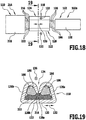
- the individual conductors 106 of the electrical lines 102a and 102b are arranged on the side of the individual conductors 216 of the electrical line element 214 facing away from the closed side 120 of the crimping element 118, as shown in the cross section of FIG Fig. 19 can be seen.
- the crimping element preform 148 is plastically deformed in such a way that the crimping element preform 148 is converted into the Figures 17 to 19
- the edge regions 126a, 126b of the crimping element 118 are bent around the end sections 196 of the individual conductors 106 of the electrical lines 102a, 102b that are not provided with the sheath 108 and are pressed against the individual conductors 106 in such a way that the end sections 196 of the individual conductors 106 enclosed by the crimping element 118 are compacted and pressed together with a force fit.
- the end sections 222 of the individual conductors 216 of the electrical line element 214 which are not provided with the sheath 218, are pressed against the individual conductors 106 of the electrical lines 102a, 102b in such a way that the End sections 222 of the individual conductors 216 enclosed by the crimping element 118 are compacted and pressed with one another in a non-positive manner and with the individual conductors 106 of the electrical lines 102a, 102b.
- the space volume of the electrical lines 102a, 102b remaining between the individual conductors 106 and the space volume of the electrical line element 214 remaining between the individual conductors 216 in the region of the crimping element 118 is reduced.
- the assembly 100 comprising the electrical lines 102a and 102b, the crimping element 118 and the electrical line element 214 is removed from the crimping tool 152 and inserted into an ultrasonic welding tool 198, as shown for example in FIG Fig. 12 is shown, introduced.
- the assembly 100 is placed on the anvil 202 in such a way that the contact surface 122 of the crimping element 118 comes to rest on the contact surface 204 of the anvil 202.
- the sonotrode 200 is then brought up to the assembly 100 in such a way that the contact surface 208 of the sonotrode 200 extending in the longitudinal direction 206 of the sonotrode 200 comes into contact with the open side 124 of the crimping element 118.
- the ultrasonic welding process is carried out on the assembly 100 by means of the sonotrode 200, through which the individual conductors 106 of the electrical lines 102a, 102b with one another and with the individual conductors 216 of the electrical line element 214 and with the inside of the crimping element 118 and the individual conductors 216 of the electrical line element 214 with one another , are welded to the individual conductors 106 of the electrical lines 102a, 102b and to the inside of the crimping element 118 by friction welding and are thus firmly connected.
- the ultrasonic welding tool 198 is opened and the completed assembly 100, in which the individual conductors 106 of the electrical lines 102a, 102b are connected to the individual conductors 216 of the electrical line element 214 both by crimping using the crimping element 118 and by ultrasonic welding taken from the ultrasonic welding tool 198.
Description
Die vorliegende Erfindung betrifft ein Verfahren zum Herstellen einer elektrisch leitenden Verbindung zwischen einer elektrischen Leitung, die mehrere Einzelleiter umfasst, und einem elektrisch leitenden Bauteil.The present invention relates to a method for producing an electrically conductive connection between an electrical line, which comprises a plurality of individual conductors, and an electrically conductive component.
Bei einem bekannten Verfahren dieser Art werden Aluminiumlitzen einer elektrischen Leitung mit einem vernickelten und versilberten Kupferschwert durch Ultraschallschweißung verbunden.In a known method of this type, aluminum strands of an electrical line are connected to a nickel-plated and silver-plated copper sword by ultrasonic welding.
Hierbei besteht das Problem, dass die Verbindung zwischen den Aluminiumlitzen und dem Kupferschwert unter dem Einfluss von Luftfeuchtigkeit und/oder NaCI-Lösung korrodiert, so dass die Zugfestigkeit der Verbindung durch Korrosion stark absinkt.The problem here is that the connection between the aluminum strands and the copper sword corrodes under the influence of atmospheric humidity and / or NaCl solution, so that the tensile strength of the connection drops sharply due to corrosion.
Die
Der vorliegenden Erfindung liegt die Aufgabe zugrunde, ein Verfahren zum Herstellen einer elektrisch leitenden Verbindung zwischen einer elektrischen Leitung, die mehrere Einzelleiter umfasst, und einem elektrisch leitenden Bauteil zu schaffen, welches einfach und vorzugsweise ohne Verwendung eines zusätzlichen Korrosionsschutzes durchführbar ist und dennoch zu einer korrosionsbeständigen Verbindung zwischen den Einzelleitern der elektrischen Leitung und dem elektrisch leitenden Bauteil führt.The present invention is based on the object of creating a method for producing an electrically conductive connection between an electrical line comprising several individual conductors and an electrically conductive component which can be carried out easily and preferably without the use of additional corrosion protection and yet becomes corrosion-resistant Connection between the individual conductors of the electrical line and the electrically conductive component leads.
Diese Aufgabe wird durch ein Verfahren nach Anspruch 1 gelöst.This object is achieved by a method according to
Der vorliegenden Erfindung liegt das Konzept zugrunde, eine mechanische Fixierung der Einzelleiter durch das Vercrimpen mit einer verbesserten Kompaktierung der Einzelleiter beim Crimpen und beim Ultraschallschweißvorgang zu kombinieren.The present invention is based on the concept of combining mechanical fixation of the individual conductors by crimping with improved compacting of the individual conductors during crimping and during the ultrasonic welding process.
Durch die Crimpung und den anschließenden Ultraschallschweißvorgang werden die Einzelleiter so stark kompaktiert, dass die Gesamtheit der Einzelleiter einem Vollmaterial nahekommt. Die Korrosion findet an den so kompaktierten Einzelleitern nicht genügend Angriffsfläche, um die Verbindungsstelle entscheidend zu schädigen.By crimping and the subsequent ultrasonic welding process, the individual conductors are compacted to such an extent that the entirety of the individual conductors comes close to being a solid material. The corrosion does not find enough attack surface on the compacted individual conductors to damage the connection point decisively.
Die zusätzliche mechanische Sicherung und/oder Fixierung der Einzelleiter durch die Crimpung verhindert zusätzlich, dass die Einzelleiter sich aus der Verbindung mit dem elektrisch leitenden Bauteil lösen können, selbst wenn dennoch ein korrosives Geschehen stattfindet.The additional mechanical securing and / or fixing of the individual conductors by means of the crimping additionally prevents the individual conductors from being able to detach from the connection with the electrically conductive component, even if a corrosive event nevertheless occurs.
Bei der Crimpung, das heißt beim Erzeugen des die Einzelleiter abschnittsweise umschließenden Crimpelements, werden die Einzelleiter vorzugsweise vor dem Ultraschallschweißvorgang vollständig durch das Crimpelement umschlossen.During crimping, that is to say when producing the crimping element which partially encloses the individual conductors, the individual conductors are preferably completely enclosed by the crimping element before the ultrasonic welding process.
Hierdurch wird eine ungleichmäßige Verteilung der Einzelleiter und somit eine ungleichmäßige Verpressung beim Ultraschallschweißvorgang vermieden.This avoids an uneven distribution of the individual conductors and thus an uneven compression during the ultrasonic welding process.
Die vorzugsweise vor dem Ultraschallschweißvorgang durchgeführte Crimpung bringt die Einzelleiter in eine definierte Form, was zu höherer Prozesssicherheit beim anschließenden Ultraschallschweißvorgang führt.The crimping, which is preferably carried out before the ultrasonic welding process, brings the individual conductors into a defined shape, which leads to greater process reliability in the subsequent ultrasonic welding process.
Durch die bessere Kompaktierung der Einzelleiter und die deutlich verbesserte mechanische Fixierung durch das Crimpen kann erreicht werden, dass die Verbindung zwischen der elektrischen Leitung und dem elektrisch leitenden Bauteil eine höhere Festigkeit aufweist und nicht durch ein Lösen der Ultraschallschweißverbindung, sondern allenfalls durch ein Materialversagen der Einzelleiter unterbrochen wird. Es reißen also eher die Einzelleiter hinter der Schweißung ab, bevor die Verbindung sich an der Schweißstelle selbst löst.Due to the better compacting of the individual conductors and the significantly improved mechanical fixation through crimping, it can be achieved that the connection between the electrical line and the electrically conductive component has a higher strength and not through a loosening of the ultrasonic welded connection, but at best through a material failure of the individual conductors is interrupted. It is more likely that the individual conductors behind the weld tear off before the connection loosens at the weld point itself.
Die Ausgangswerte für die Zugfestigkeit der Verbindung zwischen der elektrischen Leitung und dem elektrisch leitenden Bauteil sind schon unmittelbar nach der Herstellung der elektrisch leitenden Verbindung deutlich höher als bei bekannten Verbindungsverfahren. Da die Zugfestigkeit der Verbindung nicht mehr durch das Versagen der Schweißstelle, sondern durch das Materialversagen der Einzelleiter bestimmt wird, wird die Prozessfähigkeit deutlich erhöht, da die Einzelleiter stets bei ähnlichen Werten der Zugbelastung reißen.The initial values for the tensile strength of the connection between the electrical line and the electrically conductive component are already significantly higher immediately after the electrically conductive connection has been established than with known connection methods. Since the tensile strength of the connection is no longer determined by the failure of the weld, but by the material failure of the individual conductors, the process capability is significantly increased, since the individual conductors always tear at similar tensile loads.
Durch das Umschließen mit dem Crimpelement und die Verschweißung zumindest eines Teils der Einzelleiter mit dem Crimpelement werden die Einzelleiter geschützt. Ferner wird ein Einschnüren der Einzelleiter während des Ultraschallschweißvorgangs vermieden, welches zu einem leichteren Abreißen der Einzelleiter führen könnte. Bei dem erfindungsgemäßen Verfahren werden somit an den Einzelleitern keine Sollbruchstellen erzeugt.The individual conductors are protected by enclosing with the crimping element and welding at least a part of the individual conductors to the crimping element. Furthermore, a constriction of the individual conductors during the ultrasonic welding process is avoided, which could lead to an easier tearing of the individual conductors. In the method according to the invention, no predetermined breaking points are thus generated on the individual conductors.
Durch den höheren Kompaktierungsgrad und das vollständige Umschließen der Schweißstelle mit dem Material des Crimpelements wird die Angriffsfläche für die Korrosion deutlich reduziert, was die Korrosionsbeständigkeit der so hergestellten Verbindung deutlich erhöht.Due to the higher degree of compaction and the complete enclosure of the welding point with the material of the crimping element, the attack surface for the corrosion is significantly reduced, which significantly increases the corrosion resistance of the connection thus produced.
Insbesondere kann eine nach dem erfindungsgemäßen Verfahren hergestellte Verbindungsstelle zwischen der elektrischen Leitung und dem elektrisch leitenden Bauteil ohne Aufbringen von Korrosionsschutzmedien auf die Verbindungsstelle eingesetzt werden.In particular, a connection point produced by the method according to the invention between the electrical line and the electrically conductive component can be used without applying corrosion protection media to the connection point.
Bei einer bevorzugten Ausgestaltung des erfindungsgemäßen Verfahrens ist vorgesehen, dass die Sonotrode von dem Crimp-Werkzeug verschieden ist.In a preferred embodiment of the method according to the invention, it is provided that the sonotrode is different from the crimping tool.
Der Crimpvorgang und der Ultraschallschweißvorgang werden also vorzugsweise nacheinander, in verschiedenen Werkzeugen, durchgeführt.The crimping process and the ultrasonic welding process are therefore preferably carried out one after the other in different tools.
Vorzugsweise wird der Ultraschallschweißvorgang erst nach der Erzeugung des Crimpelements begonnen.The ultrasonic welding process is preferably only started after the crimping element has been produced.
Bei einer bevorzugten Ausgestaltung der Erfindung ist vorgesehen, dass die Einzelleiter sowohl mittels des Crimp-Werkzeugs als auch mittels der Sonotrode des Ultraschallschweißwerkzeugs kompaktiert werden.In a preferred embodiment of the invention it is provided that the individual conductors are compacted both by means of the crimping tool and by means of the sonotrode of the ultrasonic welding tool.
Das zwischen den Einzelleitern der elektrischen Leitung im Bereich des Crimpelements verbleibende Zwischenraumvolumen nimmt also beim Crimpvorgang ab und wird beim Ultraschallschweißvorgang weiter reduziert.The space volume remaining between the individual conductors of the electrical line in the area of the crimping element thus decreases during the crimping process and is further reduced during the ultrasonic welding process.
Eine gute Kompaktierung der Einzelleiter wird insbesondere erzielt, wenn der Schweißdruck der Sonotrode zumindest zeitweise mindestens ungefähr 3 bar, insbesondere mindestens ungefähr 4 bar, beispielsweise mindestens ungefähr 5 bar, beträgt.Good compaction of the individual conductors is achieved in particular when the welding pressure of the sonotrode is at least temporarily at least approximately 3 bar, in particular at least approximately 4 bar, for example at least approximately 5 bar.
Als besonders günstig hat sich in Versuchen ein Schweißdruck von ungefähr 5 bar erwiesen.A welding pressure of approximately 5 bar has proven to be particularly favorable in tests.
Ferner hat es sich für die Kompaktierung der Einzelleiter als günstig erwiesen, wenn die Schweißzeit des Ultraschallschweißvorgangs mindestens ungefähr 1,0 Sekunden, vorzugsweise mindestens ungefähr 1,5 Sekunden, insbesondere mindestens ungefähr 3 Sekunden, beträgt.Furthermore, it has proven to be beneficial for compacting the individual conductors if the welding time of the ultrasonic welding process is at least approximately 1.0 seconds, preferably at least approximately 1.5 seconds, in particular at least approximately 3 seconds.
Die Schweißzeit des Ultraschallschweißvorgangs ist insbesondere die Zeit, die benötigt wird, um das Crimpelement, welches die Einzelleiter umschließt, auf eine vorgegebene Endhöhe (sogenannte Endknotenhöhe) zu verformen (beispielsweise auf eine Endknotenhöhe von 7,5 mm).The welding time of the ultrasonic welding process is in particular the time that is required to open the crimping element which surrounds the individual conductors to deform a specified final height (so-called final node height) (for example to a final node height of 7.5 mm).
Grundsätzlich könnte vorgesehen sein, dass die Crimpelement-Vorform ein von dem elektrisch leitenden Bauteil separat hergestelltes Bauelement ist.In principle, it could be provided that the crimping element preform is a component produced separately from the electrically conductive component.
Bei einer bevorzugten Ausgestaltung der Erfindung ist jedoch vorgesehen, dass die Crimpelement-Vorform einstückig mit dem elektrisch leitenden Bauteil ausgebildet ist.In a preferred embodiment of the invention, however, it is provided that the crimping element preform is formed in one piece with the electrically conductive component.
Die Crimpelement-Vorform und/oder das daraus gebildete Crimpelement weisen vorzugsweise eine Materialstärke von mindestens ungefähr 1 mm, insbesondere mindestens ungefähr 1,5 mm, beispielsweise mindestens ungefähr 1,8 mm, auf.The crimping element preform and / or the crimping element formed therefrom preferably have a material thickness of at least approximately 1 mm, in particular at least approximately 1.5 mm, for example at least approximately 1.8 mm.
Beispielsweise kann die Crimpelement-Vorform und/oder das daraus gebildete Crimpelement ein, vorzugsweise beschichtetes, Kupfermaterial mit einer Materialstärke von ungefähr 1,8 mm umfassen.For example, the crimping element preform and / or the crimping element formed therefrom can comprise a, preferably coated, copper material with a material thickness of approximately 1.8 mm.
Um ein unerwünschtes Aufbiegen des Crimpelements zu verhindern, ist es günstig, wenn die Crimpelement-Vorform und/oder das elektrisch leitende Bauteil ein metallisches Material mit einer Zugfestigkeit Rm von mehr als 250 N/mm2, vorzugsweise von mehr als 300 N/mm2, insbesondere von mehr als 350 N/mm2, umfasst.In order to prevent undesired bending of the crimping element, it is advantageous if the crimping element preform and / or the electrically conductive component is a metallic material with a tensile strength R m of more than 250 N / mm 2 , preferably more than 300 N / mm 2 , in particular of more than 350 N / mm 2 .
Beispielsweise kann die Crimpelement-Vorform und/oder das elektrisch leitende Bauteil ein Kupfermaterial mit einer Zugfestigkeit von mindestens ungefähr 360 N/mm2 umfassen.For example, the crimping element preform and / or the electrically conductive component can comprise a copper material with a tensile strength of at least approximately 360 N / mm 2 .
Bei einer bevorzugten Ausgestaltung der Erfindung ist vorgesehen, dass die Crimpelement-Vorform und/oder das elektrisch leitende Bauteil Kupfer umfasst, vorzugsweise als Hauptbestandteil.In a preferred embodiment of the invention it is provided that the crimping element preform and / or the electrically conductive component comprises copper, preferably as the main component.
Als Hauptbestandteil eines Materials gilt dabei derjenige Bestandteil, welcher den höchsten Gewichtsanteil an dem Material aufweist.The main component of a material is that component which has the highest percentage by weight of the material.
Insbesondere kann vorgesehen sein, dass die Crimpelement-Vorform und/oder das elektrisch leitende Bauteil aus Kupfer oder einer Kupferlegierung gebildet sind.In particular, it can be provided that the crimping element preform and / or the electrically conductive component are formed from copper or a copper alloy.
Ferner hat es sich als günstig erwiesen, wenn die Crimpelement-Vorform und/oder das elektrisch leitende Bauteil eine Beschichtung aufweist, welche Nickel und/oder Silber umfasst.Furthermore, it has proven to be advantageous if the crimping element preform and / or the electrically conductive component has a coating which comprises nickel and / or silver.
Die Einzelleiter können grundsätzlich aus jedem Material gebildet sein, welches eine ausreichende elektrische Leitfähigkeit aufweist.The individual conductors can in principle be formed from any material that has sufficient electrical conductivity.
Bei einer bevorzugten Ausgestaltung der Erfindung ist vorgesehen, dass die Einzelleiter Aluminium umfassen, insbesondere als Hauptbestandteil.In a preferred embodiment of the invention it is provided that the individual conductors comprise aluminum, in particular as a main component.
Beispielsweise kann vorgesehen sein, dass die Einzelleiter aus Aluminium oder aus einer Aluminiumlegierung gebildet sind.For example, it can be provided that the individual conductors are formed from aluminum or from an aluminum alloy.
Günstig ist es, wenn die Crimpelement-Vorform aus einem Material gebildet ist, welches eine höhere mechanische Festigkeit aufweist als das Material, aus dem zumindest ein Teil der mittels des Crimpelements gecrimpten Einzelleiter gebildet ist. Hierdurch kann insbesondere erreicht werden, dass eine ausreichend hohe Schweißenergie beim Ultraschallschweißvorgang in das Material der Einzelleiter einbringbar ist.It is favorable if the crimping element preform is formed from a material which has a higher mechanical strength than the material from which at least some of the individual conductors crimped by means of the crimping element are formed. In this way, it can be achieved in particular that a sufficiently high welding energy can be introduced into the material of the individual conductors during the ultrasonic welding process.
Beispielsweise kann vorgesehen sein, dass das Material, aus dem die Crimpelement-Vorform gebildet ist, eine höhere Zugfestigkeit, eine höhere Streckgrenze und/oder einen höheren Elastizitätsmodul aufweist als das Material, aus dem zumindest ein Teil der Einzelleiter gebildet ist.For example, it can be provided that the material from which the crimping element preform is formed has a higher tensile strength, a higher yield point and / or a higher modulus of elasticity than the material from which at least a part of the individual conductors is formed.
Vorzugsweise beträgt die Zugfestigkeit des Materials, aus dem die Crimpelement-Vorform gebildet ist, mindestens das Doppelte, insbesondere mindestens das Dreifache, der Zugfestigkeit des Materials, aus dem zumindest ein Teil der Einzelleiter gebildet ist.The tensile strength of the material from which the crimping element preform is formed is at least twice, in particular at least three times, the tensile strength of the material from which at least some of the individual conductors are formed.
Ferner beträgt vorzugsweise die Streckgrenze des Materials, aus dem die Crimpelement-Vorform gebildet ist, mindestens das Doppelte, insbesondere mindestens das Fünffache, besonders bevorzugt mindestens das Zehnfache, der Streckgrenze des Materials, aus dem zumindest ein Teil der Einzelleiter gebildet ist.Furthermore, the yield point of the material from which the crimping element preform is formed is at least twice, in particular at least five times, particularly preferably at least ten times, the yield point of the material from which at least some of the individual conductors are formed.
Das Material, aus dem die Crimpelement-Vorform gebildet ist, kann beispielsweise das Kupfermaterial mit der Bezeichnung Cu R360 nach EN 13599 sein, welches eine Zugfestigkeit von 360 MPa und eine Streckgrenze von 320 MPa aufweist.The material from which the crimping element preform is formed can be, for example, the copper material with the designation Cu R360 according to EN 13599, which has a tensile strength of 360 MPa and a yield point of 320 MPa.
Das Material, aus dem zumindest ein Teil der mittels des Crimpelements gecrimpten Einzelleiter, insbesondere alle der mittels des Crimpelements gecrimpten Einzelleiter, gebildet ist, kann beispielsweise das Aluminiummaterial mit der Bezeichnung AW-AI 99,5 nach EN 573/485 sein, welches eine Zugfestigkeit von 65 bis 95 MPa und eine Streckgrenze von 20 MPa aufweist.The material from which at least some of the individual conductors crimped by means of the crimping element, in particular all of the individual conductors crimped by means of the crimping element, is formed can be, for example, the aluminum material with the designation AW-AI 99.5 according to EN 573/485, which has tensile strength from 65 to 95 MPa and a yield strength of 20 MPa.
Das erfindungsgemäße Verfahren eignet sich insbesondere zur Herstellung einer elektrisch leitenden Verbindung zwischen einer elektrischen Leitung mit einem relativ großen Leitungsquerschnitt und einem elektrisch leitenden Bauteil.The method according to the invention is particularly suitable for producing an electrically conductive connection between an electrical line with a relatively large line cross-section and an electrically conductive component.
Es ist vorgesehen, dass die gesamte Querschnittsfläche der Einzelleiter der elektrischen Leitung im Bereich des Crimpelements, insbesondere nach der Herstellung der elektrisch leitenden Verbindung, mehr als 50 mm2, insbesondere mehr als 55 mm2, beispielsweise ungefähr 59 mm2, beträgt.It is provided that the total cross-sectional area of the individual conductors of the electrical line in the area of the crimping element, in particular after the electrically conductive connection has been made, is more than 50 mm 2 , in particular more than 55 mm 2 , for example approximately 59 mm 2 .
Für eine besonders gute Kompaktierung der Einzelleiter beim Ultraschallschweißvorgang hat es sich als günstig erwiesen, wenn die Sonotrode eine Kontaktfläche mit einer Längsrichtung aufweist, wobei die Längsrichtung der Kontaktfläche während des Ultraschallschweißvorgangs mit freien Rändern des Crimpelements einen Winkel von mehr als 45°, vorzugsweise einen Winkel von mehr als 60°, insbesondere einen Winkel von ungefähr 90°, einschließt.For particularly good compaction of the individual conductors during the ultrasonic welding process, it has proven to be advantageous if the sonotrode has a contact surface with a longitudinal direction, the longitudinal direction of the contact surface during the ultrasonic welding process with free edges of the crimping element at an angle of more than 45 °, preferably an angle of more than 60 °, in particular an angle of approximately 90 °.
Ferner ist es günstig, wenn das elektrisch leitende Bauteil einen Schweißbereich, an dem zumindest ein Teil der Einzelleiter der elektrischen Leitung festgelegt wird, und einen Kontaktbereich umfasst, wobei der Kontaktbereich über einen abgekanteten Bereich mit dem Schweißbereich verbunden ist.It is also advantageous if the electrically conductive component comprises a welding area, on which at least a part of the individual conductors of the electrical line is fixed, and a contact area, the contact area being connected to the welding area via a beveled area.
Insbesondere kann vorgesehen sein, dass der Kontaktbereich über eine Abkantung um einen Winkel von mehr als 45°, vorzugsweise um einen Winkel von mehr als 60°, beispielsweise um einen Winkel von ungefähr 90°, mit dem Schweißbereich verbunden ist.In particular, it can be provided that the contact area is connected to the welding area via a fold at an angle of more than 45 °, preferably at an angle of more than 60 °, for example at an angle of approximately 90 °.
Der abgekantete Bereich kann sich längs einer Abkantlinie erstrecken, welche im Wesentlichen parallel zu einer Querrichtung des Crimpelements gerichtet ist.The folded region can extend along a folded line which is directed essentially parallel to a transverse direction of the crimping element.
Alternativ hierzu kann auch vorgesehen sein, dass der abgekantete Bereich sich längs einer Abkantlinie erstreckt, welche quer zu der Querrichtung des Crimpelements gerichtet ist.As an alternative to this, it can also be provided that the folded area extends along a folded line which is directed transversely to the transverse direction of the crimping element.
Insbesondere kann vorgesehen sein, dass die Abkantlinie mit der Querrichtung des Crimpelements einen Winkel von mindestens ungefähr 10°, insbesondere von mindestens ungefähr 20°, einschließt.In particular, it can be provided that the folding line encloses an angle of at least approximately 10 °, in particular of at least approximately 20 °, with the transverse direction of the crimping element.
Ferner ist vorzugsweise vorgesehen, dass die Abkantlinie mit der Querrichtung des Crimpelements einen Winkel von höchstens ungefähr 60°, insbesondere von höchstens ungefähr 45°, einschließt.Furthermore, it is preferably provided that the folding line encloses an angle of at most approximately 60 °, in particular of at most approximately 45 °, with the transverse direction of the crimping element.
Bei einer besonderen Ausgestaltung der Erfindung ist vorgesehen, dass nicht nur eine elektrische Leitung, sondern mehrere elektrische Leitungen, insbesondere zwei elektrische Leitungen, mit dem elektrisch leitenden Bauteil elektrisch leitend verbunden werden, wobei ein die Einzelleiter mehrerer elektrischer Leitungen abschnittsweise umschließendes Crimpelement aus einer Crimpelement-Vorform erzeugt wird.In a particular embodiment of the invention, it is provided that not only one electrical line, but several electrical lines, in particular two electrical lines, are electrically conductively connected to the electrically conductive component, with a crimping element that partially encloses the individual conductors of several electrical lines and consists of a crimping element Preform is generated.
Ferner kann vorgesehen sein, dass das elektrisch leitende Bauteil, mit dem eine oder mehrere elektrische Leitungen elektrisch leitend verbunden werden, ein elektrisches Leitungselement umfasst, welches seinerseits mehrere Einzelleiter oder Litzen umfasst.Furthermore, it can be provided that the electrically conductive component to which one or more electrical lines are connected in an electrically conductive manner comprises an electrical line element which in turn comprises a plurality of individual conductors or strands.
Dabei ist vorzugsweise vorgesehen, dass das Crimpelement die Einzelleiter des elektrischen Leitungselements abschnittsweise umschließt.It is preferably provided here that the crimping element encloses the individual conductors of the electrical line element in sections.
Insbesondere umschließt das Crimpelement in diesem Fall also sowohl die Einzelleiter der einen elektrischen Leitung oder der mehreren elektrischen Leitungen als auch die Einzelleiter des elektrischen Leitungselements.In particular, in this case the crimping element thus encloses both the individual conductors of the one electrical line or of the multiple electrical lines and the individual conductors of the electrical line element.
Vorzugsweise ist dabei vorgesehen, dass die Einzelleiter der einen elektrischen Leitung oder der mehreren elektrischen Leitungen einerseits und die Einzelleiter des elektrischen Leitungselements andererseits einander in der Längsrichtung des Crimpelements überlappen.It is preferably provided here that the individual conductors of the one electrical line or of the plurality of electrical lines on the one hand and the individual conductors of the electrical line element on the other hand overlap one another in the longitudinal direction of the crimping element.
Bei einer besonderen Ausgestaltung der Erfindung kann vorgesehen sein, dass die Einzelleiter des elektrischen Leitungselements aus einem Material gebildet sind, das von dem Material der Einzelleiter der einen elektrischen Leitung oder der mehreren elektrischen Leitungen verschieden ist.In a particular embodiment of the invention it can be provided that the individual conductors of the electrical line element are formed from a material that is different from the material of the individual conductors of the one electrical line or of the multiple electrical lines.
So kann beispielsweise vorgesehen sein, dass die Einzelleiter des elektrischen Leitungselements Aluminium umfassen und die Einzelleiter der einen elektrischen Leitung oder der mehreren elektrischen Leitungen Kupfer umfassen.For example, it can be provided that the individual conductors of the electrical conduction element comprise aluminum and the individual conductors of the one electrical line or of the plurality of electrical lines comprise copper.
Alternativ hierzu kann auch vorgesehen sein, dass der Kontaktbereich ohne Abkantung in den Schweißbereich übergeht.As an alternative to this, it can also be provided that the contact area merges into the welding area without a bevel.
Das elektrisch leitende Bauteil kann insbesondere als ein Modulverbinder einer elektrochemischen Vorrichtung ausgebildet sein.The electrically conductive component can in particular be designed as a module connector of an electrochemical device.
Die elektrochemische Vorrichtung kann insbesondere als ein Akkumulator, insbesondere als ein Lithium-Ionen-Akkumulator, ausgebildet sein.The electrochemical device can in particular be designed as an accumulator, in particular as a lithium-ion accumulator.
Die vorliegende Erfindung betrifft ferner eine Baugruppe, welche eine elektrische Leitung, die mehrere Einzelleiter umfasst, und ein mit der elektrischen Leitung verbundenes elektrisch leitendes Bauteil umfasst.The present invention further relates to an assembly which comprises an electrical line, which comprises a plurality of individual conductors, and an electrically conductive component connected to the electrical line.
Der vorliegenden Erfindung liegt die weitere Aufgabe zugrunde, eine solche Baugruppe so auszubilden, dass sie einfach montierbar ist und dennoch eine hohe Korrosionsbeständigkeit aufweist.The present invention is based on the further object of designing such an assembly in such a way that it is easy to assemble and yet has a high level of corrosion resistance.
Diese Aufgabe wird durch eine Baugruppe nach Anspruch 15 gelöst.This object is achieved by an assembly according to claim 15.
Eine solche Baugruppe ist durch das vorstehend beschriebene erfindungsgemäße Verfahren hergestellt. Weitere Merkmale und Vorteile der Erfindung sind Gegenstand der nachfolgenden Beschreibung und der zeichnerischen Darstellung eines Ausführungsbeispiels.Such an assembly is produced by the method according to the invention described above. Further features and advantages of the invention are the subject of the following description and the drawing of an exemplary embodiment.
In den Zeichnungen zeigen:
- Fig. 1
- eine schematische perspektivische Darstellung einer Baugruppe, welche eine elektrische Leitung mit mehreren Einzelleitern, ein die Einzelleiter abschnittsweise umschließendes Crimpelement und ein durch Ultraschallschweißen mit zumindest einem Teil der Einzelleiter verbundenes elektrisch leitendes Bauteil umfasst;
- Fig. 2
- eine aus einem ebenen Ausgangsmaterial herausgetrennte Bauelement-Vorform;
- Fig. 3
- eine perspektivische Darstellung des elektrisch leitenden Bauteils mit einer Crimpelement-Vorform;
- Fig. 4
- eine Seitenansicht des elektrisch leitenden Bauteils mit der Crimpelement-Vorform;
- Fig. 5
- eine Vorderansicht des elektrisch leitenden Bauteils mit der Crimpelement-Vorform, mit der Blickrichtung in
Richtung des Pfeiles 5 inFig. 4 ; - Fig. 6
- eine perspektivische Darstellung eines Crimp-Werkzeugs, welches ein Werkzeugoberteil, ein Werkzeugunterteil und ein Positionierelement umfasst;
- Fig. 7
- eine Darstellung des Crimp-Werkzeugs und der Crimpelement-Vorform des elektrisch leitenden Bauteils vor einem Crimpvorgang zum Erzeugen eines Crimpelements aus der Crimpelement-Vorform;
- Fig. 8
- eine der
Fig. 7 entsprechende Darstellung des Crimp-Werkzeugs und des Crimpelements nach dem Crimpvorgang, durch welchen das Crimpelement aus der Crimpelement-Vorform erzeugt worden ist; - Fig. 9
- eine perspektivische Darstellung des elektrisch leitenden Bauteils mit dem Crimpelement;
- Fig. 10
- eine Seitenansicht des elektrisch leitenden Bauteils mit dem Crimpelement;
- Fig. 11
- eine Vorderansicht des elektrisch leitenden Bauteils mit dem Crimpelement, mit der Blickrichtung in
Richtung des Pfeiles 11 inFig. 10 ; - Fig. 12
- eine perspektivische Darstellung einer Sonotrode, eines Ambosses und der elektrischen Leitung mit mehreren Einzelleitern, die abschnittsweise von dem Crimpelement des elektrisch leitenden Bauteils umschlossen sind;
- Fig. 13
- eine schematische perspektivische Darstellung einer zweiten Ausführungsform einer Baugruppe, welche eine elektrische Leitung mit mehreren Einzelleitern, ein die Einzelleiter abschnittsweise umschließendes Crimpelement und ein durch Ultraschallschweißen mit zumindest einem Teil der Einzelleiter verbundenes elektrisch leitendes Bauteil umfasst, wobei das elektrisch leitende Bauteil einen Schweißbereich, an dem zumindest ein Teil der Einzelleiter der elektrischen Leitungen festgelegt ist, und einen Kontaktbereich umfasst, der über einen abgekanteten Bereich mit dem Schweißbereich verbunden ist, und wobei der abgekantete Bereich sich längs einer Abkantlinie erstreckt, welche quer zu einer Querrichtung des Crimpelements gerichtet ist;
- Fig. 14
- eine aus einem ebenen Ausgangsmaterial herausgetrennte Bauelement-Vorform der zweiten Ausführungsform der Baugruppe;
- Fig. 15
- eine perspektivische Darstellung des elektrisch leitenden Bauteils mit einer Crimpelement-Vorform bei der zweiten Ausführungsform der Baugruppe;
- Fig. 16
- eine Draufsicht von oben auf das elektrisch leitende Bauteil mit der Crimpelement-Vorform bei der zweiten Ausführungsform der Baugruppe;
- Fig. 17
- eine schematische perspektivische Darstellung einer dritten Ausführungsform einer Baugruppe, welche zwei elektrische Leitungen mit jeweils mehreren Einzelleitern, ein elektrisches Leitungselement mit mehreren Einzelleitern als elektrisch leitendes Bauteil und ein sowohl die Einzelleiter der elektrischen Leitungen als auch die Einzelleiter des elektrischen Leitungselements abschnittsweise umschließendes Crimpelement umfasst, wobei zumindest ein Teil der Einzelleiter der elektrischen Leitungen mit zumindest einem Teil der Einzelleiter des elektrischen Leitungselements durch Ultraschallschweißen verbunden ist;
- Fig. 18
- eine Seitenansicht der Baugruppe aus
Fig. 17 , mit der Blickrichtung inRichtung des Pfeiles 18 inFig. 17 ; - Fig. 19
- einen Querschnitt durch das Crimpelement der Baugruppe aus
Fig. 18 und die abschnittsweise von dem Crimpelement umschlossenen Einzelleiter der elektrischen Leitungen und des elektrischen Leitungselements, längs der Linie 19 - 19 inFig. 18 ; - Fig. 20
- eine aus einem ebenen Ausgangsmaterial herausgetrennte Crimpelement-Ausgangsform;
- Fig. 21
- eine perspektivische Darstellung einer Crimpelement-Vorform der dritten Ausführungsform der Baugruppe, welche aus der in
Fig. 20 dargestellten, im Wesentlichen ebenen Crimpelement-Ausgangsform dadurch erzeugt worden ist, dass Randbereiche des späteren Crimpelements aus der Ebene der geschlossenen Seite des Crimpelements herausgebogen worden sind; und - Fig. 22
- eine Vorderansicht der Crimpelement-Vorform aus
Fig. 21 , mit der Blickrichtung inRichtung des Pfeiles 22 inFig. 21 .
- Fig. 1
- a schematic perspective illustration of an assembly which comprises an electrical line with several individual conductors, a crimping element that partially encloses the individual conductors and an electrically conductive component connected to at least a part of the individual conductors by ultrasonic welding;
- Fig. 2
- a component preform separated from a flat starting material;
- Fig. 3
- a perspective view of the electrically conductive component with a crimping element preform;
- Fig. 4
- a side view of the electrically conductive component with the crimping element preform;
- Fig. 5
- a front view of the electrically conductive component with the crimping element preform, looking in the direction of
arrow 5 in FIGFig. 4 ; - Fig. 6
- a perspective view of a crimping tool comprising an upper tool part, a lower tool part and a positioning element;
- Fig. 7
- a representation of the crimping tool and the crimping element preform of the electrically conductive component before a crimping process for producing a crimping element from the crimping element preform;
- Fig. 8
- one of the
Fig. 7 corresponding representation of the crimping tool and the crimping element after the crimping process, by which the crimping element has been produced from the crimping element preform; - Fig. 9
- a perspective view of the electrically conductive component with the crimping element;
- Fig. 10
- a side view of the electrically conductive component with the crimping element;
- Fig. 11
- a front view of the electrically conductive component with the crimping element, looking in the direction of
arrow 11 in FIGFig. 10 ; - Fig. 12
- a perspective view of a sonotrode, an anvil and the electrical line with several individual conductors, which are enclosed in sections by the crimping element of the electrically conductive component;
- Fig. 13
- a schematic perspective illustration of a second embodiment of an assembly which comprises an electrical line with several individual conductors, a crimping element which partially encloses the individual conductors and an electrically conductive component connected by ultrasonic welding to at least a part of the individual conductors, the electrically conductive component having a welding area on which at least a part of the individual conductors of the electrical lines is fixed, and comprises a contact area which is connected to the welding area via a bent area, and wherein the bent area extends along a bent line which is directed transversely to a transverse direction of the crimping element;
- Fig. 14
- a component preform of the second embodiment of the assembly that has been separated from a flat starting material;
- Fig. 15
- a perspective view of the electrically conductive component with a crimping element preform in the second embodiment of the assembly;
- Fig. 16
- a plan view from above of the electrically conductive component with the crimping element preform in the second embodiment of the assembly;
- Fig. 17
- a schematic perspective view of a third embodiment of an assembly, which comprises two electrical lines each with several individual conductors, an electrical line element with several individual conductors as an electrically conductive component and a crimping element which partially encloses both the individual conductors of the electrical lines and the individual conductors of the electrical line element, wherein at least some of the individual conductors of the electrical lines are connected to at least some of the individual conductors of the electrical line element by ultrasonic welding;
- Fig. 18
- a side view of the assembly
Fig. 17 , looking in the direction ofarrow 18 inFig. 17 ; - Fig. 19
- a cross section through the crimping element of the assembly
Fig. 18 and the individual conductors of the electrical lines and of the electrical line element enclosed in sections by the crimping element, along the line 19-19 in FIGFig. 18 ; - Fig. 20
- a crimping element starting form separated from a flat starting material;
- Fig. 21
- a perspective view of a crimping element preform of the third embodiment of the assembly, which is from the in
Fig. 20 The illustrated, essentially flat crimping element initial shape has been produced in that edge areas of the later crimping element have been bent out of the plane of the closed side of the crimping element; and - Fig. 22
- Figure 3 is a front view of the crimp element preform
Fig. 21 , looking in the direction ofarrow 22 inFig. 21 .
Gleiche oder funktional äquivalente Elemente sind in allen Figuren mit denselben Bezugszeichen bezeichnet.Identical or functionally equivalent elements are denoted by the same reference symbols in all figures.
Eine in
In dem Schweißbereich 114 ist zumindest ein Teil der Einzelleiter 106 der elektrischen Leitung 102 durch Ultraschallschweißung mit dem elektrisch leitenden Bauteil 110 elektrisch leitend verbunden.In the
Der Schweißbereich 114 umfasst ein Crimpelement 118, welches die Einzelleiter 106 abschnittsweise umschließt. Insbesondere umschließt das Crimpelement 118 nicht mit der Umhüllung 108 versehene Endabschnitte 196 der Einzelleiter 106.The
Das Crimpelement 118 weist eine geschlossene Seite 120 mit einer durchgehenden, im Wesentlichen ebenen Anlagefläche 122 und eine der geschlossenen Seite 120 gegenüberliegende, im Folgenden als offene Seite 124 bezeichnete Seite auf, an welcher gekrümmte Randbereiche 126a und 126b des Crimpelements 118 einander gegenüberliegen.The crimping
Vorzugsweise ist dabei vorgesehen, dass freie Ränder 128a und 128b der Randbereiche 126a beziehungsweise 126b des Crimpelements 118 in einem kleinen Abstand voneinander enden oder einander berühren (siehe die
Die der geschlossenen Seite 120 des Crimpelements 118 abgewandten Kuppen 130a, 130b (siehe
Den Grund der Vertiefung 134 bilden beispielsweise die freien Ränder 128a, 128b der Randbereiche 126a beziehungsweise 126b des Crimpelements 118.The base of the
Die Querrichtung 132 des Crimpelements 118 ist senkrecht zu einer Längsrichtung 136 des Crimpelements 118 ausgerichtet, welche im Wesentlichen parallel zur Längsrichtung der elektrischen Leitung 102 und im Wesentlichen parallel zu den freien Rändern 128a und 128b des Crimpelements 118 verläuft.The
Die seitlichen freien Ränder 128a, 128b des Crimpelements 118 verbinden einen vorderen Rand 138 mit einem hinteren Rand 140 des Crimpelements 118.The lateral
Das elektrisch leitende Bauteil 110 einschließlich des Crimpelements 118 ist aus einem elektrisch leitenden metallischen Material gebildet.The electrically
Vorzugsweise umfasst das elektrisch leitende Bauteil 110 einschließlich des Crimpelements 118 ein metallisches Material mit einer Zugfestigkeit Rm von mehr als 250 N/mm2, insbesondere von mehr als 300 N/mm2, beispielsweise von mehr als 350 N/mm2.The electrically
Ferner ist vorzugsweise vorgesehen, dass das elektrisch leitende Bauteil 110 einschließlich des Crimpelements 118 Kupfer umfasst, vorzugsweise als Hauptbestandteil.Furthermore, it is preferably provided that the electrically
Als Hauptbestandteil eines Bauteils gilt dabei dasjenige Material, welches den größten Gewichtsanteil an dem betreffenden Bauteil aufweist.The main component of a component is the material that has the greatest weight proportion of the component in question.
Insbesondere kann das elektrisch leitende Bauteil 110 einschließlich des Crimpelements 118 ein Kupfermaterial mit einer Zugfestigkeit von mindestens ungefähr 360 N/mm2 umfassen.In particular, the electrically
Das elektrisch leitende Bauteil 110 einschließlich des Crimpelements 118 weist vorzugsweise eine Beschichtung auf.The electrically
Eine solche Beschichtung kann insbesondere Nickel und/oder Silber umfassen.Such a coating can in particular comprise nickel and / or silver.
Die Einzelleiter 106 der elektrischen Leitung 102 können grundsätzlich aus jedem Material gebildet sein, das eine ausreichende elektrische Leitfähigkeit aufweist.The
Insbesondere kann vorgesehen sein, dass die Einzelleiter 106 Aluminium umfassen, insbesondere aus Aluminium oder einer Aluminiumlegierung gebildet sind.In particular, it can be provided that the
Das elektrisch leitende Bauteil 110 kann beispielsweise als ein Kontaktschuh eines Modulverbinders einer elektrochemischen Vorrichtung ausgebildet sein.The electrically
Der Kontaktbereich 112 des elektrisch leitenden Bauteils 110 erstreckt sich vorzugsweise in einer Längsrichtung 142, welche insbesondere im Wesentlichen senkrecht zu der Längsrichtung 136 des Crimpelements 118 und/oder im Wesentlichen senkrecht zu der Querrichtung 132 des Crimpelements 118 ausgerichtet ist.The
Eine vorzugsweise im Wesentlichen ebene Anlagefläche 144 des Kontaktbereichs 112 schließt mit der ebenen Anlagefläche 122 des Crimpelements 118 vorzugsweise einen Winkel α von mehr als 45°, insbesondere von mehr als 60°, beispielsweise von ungefähr 90°, ein.A preferably essentially
Alternativ hierzu könnte die Anlagefläche 144 des Kontaktbereichs 112 auch im Wesentlichen parallel zu der Anlagefläche 122 des Crimpelements 118 ausgerichtet sein und insbesondere im Wesentlichen bündig mit der Anlagefläche 122 des Crimpelements 118 ausgebildet sein.As an alternative to this, the
Bei der zeichnerisch dargestellten Ausführungsform des elektrisch leitenden Bauteils 110 ist eine senkrecht zur Längsrichtung 142 des Kontaktbereichs 112 und parallel zur Anlagefläche 144 des Kontaktbereichs 112 verlaufende Querrichtung 143 des Kontaktbereichs 112 im Wesentlichen parallel zu der Querrichtung 132 des Crimpelements 118 ausgerichtet.In the embodiment of the electrically
Alternativ hierzu könnte aber auch vorgesehen sein, dass zwischen dem Kontaktbereich 112 und dem Schweißbereich 114 des elektrisch leitenden Bauteils 110 ein Zwischenbereich angeordnet ist, der an einem ersten Rand an den Schweißbereich 114 und an einem zweiten Rand an den Kontaktbereich 112 angrenzt, wobei der erste Rand und der zweite Rand nicht parallel zueinander verlaufen, sondern miteinander einen, vorzugsweise spitzen, Winkel einschließen. In diesem Fall ist dann auch die Querrichtung 143 des Kontaktbereichs 112 um diesen Winkel gegenüber der Querrichtung 132 des Crimpelements 118 verdreht.As an alternative to this, however, it could also be provided that an intermediate area is arranged between the
Zur Herstellung der vorstehend beschriebenen und in den
Eine in
One in
In dieser Bauelement-Vorform 146 liegen die geschlossene Seite 120 sowie die Randbereiche 126a und 126b des späteren Crimpelements 118 im Wesentlichen in derselben Ebene, wobei sich die beiden Randbereiche 126a und 126b in einander entgegengesetzten Richtungen längs der Querrichtung 132 des Crimpelements 118 von der geschlossenen Seite 120 weg erstrecken.In this
Aus der in
In dieser Crimpelement-Vorform 148 sind die Randbereiche 126a und 126b über gekrümmte Bereiche 150a bzw. 150b mit der geschlossenen Seite 120 der Crimpelement-Vorform 148 verbunden.In this crimping
Der Kontaktbereich 112 ist bereits in diesem Zustand über den abgekanteten Bereich 116 mit der geschlossenen Seite 120 der Crimpelement-Vorform 148 verbunden.In this state, the
Zum Verbinden der Einzelleiter 106 der elektrischen Leitung 102 mit dem elektrisch leitenden Bauteil 110 durch Vercrimpung wird beispielsweise das in
Dieses Crimp-Werkzeug 152 umfasst ein Werkzeugoberteil 154, ein Werkzeugunterteil 156 und ein Positionierelement 158.This crimping
Das Positionierelement 158 umfasst einen Sockel 160 mit einer Oberseite 162, von welcher aus sich ein hinteres Stützelement 164 und zwei seitliche Stützelemente 166 nach oben erstrecken.The
Das hintere Stützelement 164 weist eine den seitlichen Stützelementen 166 zugewandte vordere Anlegefläche 168 auf, an welche die Anlagefläche 144 des Kontaktbereichs 112 des elektrisch leitenden Bauteils 110 für den Crimpvorgang, vorzugsweise im Wesentlichen flächig, anlegbar ist.The
Die seitlichen Stützelemente 166 weisen an den einander zugewandten Seiten jeweils eine seitliche Anlegefläche 170 auf, an welcher sich der Kontaktbereich 112 des elektrisch leitenden Bauelements 110 während des Crimpvorgangs seitlich abstützt.The
Der neben dem hinteren Stützelement 164 und den seitlichen Stützelementen 166 verbleibende Rest der Oberseite 162 des Sockels 160 des Positionierelements 158 bildet eine Auflagefläche 172, an welcher das elektrisch leitende Bauteil 110 während des Crimpvorgangs mit einem Teil der Anlagefläche 122 der Crimpelement-Vorform 148, vorzugsweise im Wesentlichen flächig, anliegt.The remainder of the
Das Werkzeugoberteil 154 des Crimp-Werkzeugs 152 umfasst einen, beispielsweise im Wesentlichen quaderförmigen, Block 174, welcher an seiner während des Crimpvorgangs dem Werkzeug-Unterteil 156 zugewandten Seite eine Ausnehmung 176 aufweist, die an ihrem oberen Rand durch ein Crimp-Profil 178 berandet ist, welches komplementär zu der offenen Seite 124 des fertig hergestellten Crimpelements 118 ausgebildet ist.The
Insbesondere kann das Crimp-Profil 178 somit zwei im Wesentlichen halbkreis- oder halbkreisabschnittsförmige Profilabschnitte 180 umfassen, welche in einer Querrichtung 182 des Crimp-Werkzeugs 152, die mit der Querrichtung 132 des herzustellenden Crimpelements 118 übereinstimmt, nebeneinander angeordnet sind.In particular, the crimping
Das Werkzeugoberteil 154 ist relativ zu dem Werkzeugunterteil 156 längs einer Pressrichtung 184 beweglich, welche im Wesentlichen senkrecht zur Querrichtung 182 und im Wesentlichen senkrecht zur Längsrichtung 142 des herzustellenden Crimpelements 118 verläuft.The
Von den einander abgewandten Rändern der Profilabschnitte 180 aus erstrecken sich geneigte Begrenzungsflächen 186 der Ausnehmung 176 in dem Werkzeugoberteil 154 in Richtung auf das Werkzeugunterteil 156.From the edges of the
Die geneigten Begrenzungsflächen 186 sind gegenüber der Pressrichtung 184 des Crimp-Werkzeugs 152 unter einem spitzen Winkel geneigt.The inclined boundary surfaces 186 are inclined at an acute angle with respect to the
Das Werkzeugunterteil 156 umfasst einen Sockel 188, von welchem aus sich ein Amboss 190 in Richtung auf das Werkzeugoberteil 154 zu erstreckt.The
Der Amboss weist zwei seitliche geneigte Begrenzungsflächen 192 auf, welche vorzugsweise unter im Wesentlichen demselben spitzen Winkel gegenüber der Pressrichtung 184 des Crimp-Werkzeugs 152 geneigt sind wie die geneigten Begrenzungsflächen 186 der Ausnehmung 176 des Werkzeugoberteils 154, und eine dem Crimp-Profil 178 des Werkzeugoberteils 154 zugewandte Auflagefläche 194, welche an die Form der Anlagefläche 122 des fertig hergestellten Crimpelements 118 angepasst ist.The anvil has two lateral inclined boundary surfaces 192, which are preferably inclined at essentially the same acute angle with respect to the
Insbesondere kann also die Auflagefläche 194 im Wesentlichen eben ausgebildet sein.In particular, the
Für den Crimpvorgang, durch welchen die Einzelleiter 106 der elektrischen Leitung 102 durch Vercrimpung unter Bildung des Crimpelements 118 mit dem elektrisch leitenden Bauteil 110 verbunden werden, wird das elektrisch leitende Bauteil 110 mit der in den
Die nicht mit der Umhüllung 108 versehenen Endabschnitte 196 der Einzelleiter 106 der elektrischen Leitung 102 werden in die Crimpelement-Vorform 148, zwischen die aufgestellten Randbereiche 126a und 126b, eingelegt (die Einzelleiter 106 sind aus Gründen der Übersichtlichkeit in den
Anschließend wird das Werkzeugoberteil 154, welches zunächst in der Pressrichtung 184 von dem Werkzeugunterteil 156 beabstandet war (siehe
Durch diesen Verformungsdruck wird die Crimpelement-Vorform 148 plastisch so verformt, dass aus der Crimpelement-Vorform 148 das in
Während der Erzeugung des Crimpelements 118 aus der Crimpelement-Vorform 148 werden die Randbereiche 126a, 126b des Crimpelements 118 um die nicht mit der Umhüllung 108 versehenen Endabschnitte 196 der Einzelleiter 106 herumgebogen und so gegen die Einzelleiter 106 verpresst, dass die vom Crimpelement 118 umschlossenen Endabschnitte 196 der Einzelleiter 106 kompaktiert und kraftschlüssig miteinander verpresst werden.During the production of the crimping
Durch die Kompaktierung während des Crimpvorgangs wird das zwischen den Einzelleitern 106 verbleibende Zwischenraumvolumen der elektrischen Leitung 102 im Bereich des Crimpelements 118 verringert.As a result of the compaction during the crimping process, the interspace volume of the
Wenn der in
Nun wird das Crimp-Werkzeug 152 geöffnet, indem das Werkzeugoberteil 154 relativ zu dem Werkzeugunterteil 156 längs der Pressrichtung 184 von dem Werkzeugunterteil 156 weg bewegt wird, und die Baugruppe 100 mit dem elektrisch leitenden Bauteil 110 und der elektrischen Leitung 102, deren Einzelleiter 106 durch das Crimpelement 118 mit dem elektrisch leitenden Bauteil 110 verbunden sind, wird aus dem Crimp-Werkzeug 152 entnommen und in das schematisch in
Das Ultraschallschweißwerkzeug 198 umfasst eine Sonotrode 200 und einen der Sonotrode 200 gegenüberliegenden Amboss 202.The
Die Baugruppe 100 wird so auf den Amboss 202 aufgelegt, dass die Anlagefläche 122 des Crimpelements 118 auf einer Auflagefläche 204 des Ambosses 202 zu liegen kommt.The
Anschließend wird die Sonotrode 200 so an die Baugruppe 100 herangeführt, dass eine sich in einer Längsrichtung 206 der Sonotrode 200 erstreckende Kontaktfläche 208 der Sonotrode 200 in Kontakt mit der offenen Seite 124 des Crimpelements 118 kommt.The
Dabei ist vorzugsweise die Längsrichtung 206 der Kontaktfläche 208 der Sonotrode 200 im Wesentlichen parallel zur Querrichtung 132 des Crimpelements 118 ausgerichtet, so dass sich die Sonotrode 200 quer über die Vertiefung 134 zwischen den Randbereichen 126a und 126b des Crimpelements 118 hinweg erstreckt.The
Mittels der Sonotrode 200 wird der Ultraschallschweißvorgang an der Baugruppe 100 durchgeführt, durch welchen die Einzelleiter 106 der elektrischen Leitung 102 untereinander und mit der Innenseite des Crimpelements 118 an dem elektrisch leitenden Bauteil 110 durch Reibschweißung verschweißt und somit stoffschlüssig verbunden werden.The
Während des Ultraschallschweißvorgangs ist die Anregerichtung der Sonotrode 200 vorzugsweise im Wesentlichen parallel zu der Querrichtung 132 des Crimpelements 118 und/oder im Wesentlichen parallel zu der Längsrichtung 206 der Sonotrode 200 ausgerichtet.During the ultrasonic welding process, the direction of excitation of the
Während des Ultraschallschweißvorgangs werden das Crimpelement 118 und die Einzelleiter 106 durch die Sonotrode 200 mit einem Schweißdruck beaufschlagt.During the ultrasonic welding process, the crimping
Der Schweißdruck beträgt vorzugsweise zumindest zeitweise mindestens ungefähr 3 bar, insbesondere mindestens ungefähr 4 bar, beispielsweise mindestens ungefähr 5 bar.The welding pressure is preferably at least temporarily at least approximately 3 bar, in particular at least approximately 4 bar, for example at least approximately 5 bar.
Als besonders günstig hat sich in Versuchen ein Schweißdruck von ungefähr 5 bar erwiesen.A welding pressure of approximately 5 bar has proven to be particularly favorable in tests.
Die Schweißzeit, während welcher der Ultraschallschweißvorgang stattfindet, beträgt vorzugsweise mindestens ungefähr 1,0 Sekunden, insbesondere mindestens ungefähr 1,5 Sekunden, beispielsweise mindestens ungefähr 3 Sekunden.The welding time during which the ultrasonic welding process takes place is preferably at least approximately 1.0 seconds, in particular at least approximately 1.5 seconds, for example at least approximately 3 seconds.
Vorzugsweise ist die Zielgröße des Ultraschallschweißvorgangs die Endknotenhöhe, das heißt im vorliegenden Fall die Endhöhe des Crimpelements 118.The target variable of the ultrasonic welding process is preferably the end node height, that is to say in the present case the end height of the crimping
Die Sonotrode 200 dringt beim Ultraschallschweißvorgang in das Crimpelement 118 ein und verformt dieses. Der Ultraschallschweißvorgang wird so lange fortgesetzt, bis eine vorgegebene Endhöhe des Crimpelements 118 (beispielsweise eine Endhöhe von 7,5 mm bei einer Ausgangshöhe von 9,8 mm) erreicht ist.During the ultrasonic welding process, the
Hierdurch ist sichergestellt, dass die Kompaktierung der Einzelleiter 106 und somit auch die Korrosionsbeständigkeit immer gleich gut sind.This ensures that the compacting of the
Die während des Ultraschallschweißvorgangs über die Sonotrode 200 in die Baugruppe 100 übertragene Schweißenergie beträgt vorzugsweise mindestens ungefähr 3.000 Ws, insbesondere mindestens ungefähr 4.000 Ws, beispielsweise mindestens ungefähr 5.000 Ws, und beispielsweise höchstens ungefähr 7.000 Ws.The welding energy transmitted into
Wenn die Zielgröße des Ultraschallschweißvorgangs die Endknotenhöhe ist, ist die eingebrachte Energie eine Resultierende.If the target value of the ultrasonic welding process is the end node height, the energy introduced is a resultant.
Ein Teil der Anregung durch Ultraschall kann verloren gehen, da die Baugruppe 100 mitschwingt.Some of the excitation by ultrasound can be lost since the
Durch den Ultraschallschweißvorgang werden die Einzelleiter 106 im Bereich des Crimpelements 118 weiter kompaktiert, das heißt das zwischen den Einzelleitern 106 verbleibende Zwischenraumvolumen der elektrischen Leitung 102 wird durch den Ultraschallschweißvorgang weiter verringert.As a result of the ultrasonic welding process, the
Nach Abschluss des Ultraschallschweißvorgangs wird das Ultraschallschweißwerkzeug 198 geöffnet, und die fertiggestellte Baugruppe 100, in welcher die Einzelleiter 106 der elektrischen Leitung 102 sowohl durch Vercrimpung mittels des Crimpelements 118 als auch durch Ultraschallschweißung mit dem elektrisch leitenden Bauteil 110 verbunden sind, wird aus dem Ultraschallschweißwerkzeug 198 entnommen.After completion of the ultrasonic welding process, the
Eine in den
Dabei schließen die Abkantlinie 210 und die Querrichtung 132 des Crimpelements 118 miteinander vorzugsweise einen Winkel von mehr als ungefähr 10°, insbesondere von mehr als ungefähr 20°, ein.The
Ferner schließen die Abkantlinie 210 und die Querrichtung 132 des Crimpelements 118 vorzugsweise miteinander einen Winkel von weniger als ungefähr 60°, insbesondere von weniger als ungefähr 45°, ein.Furthermore, the
Beispielsweise kann der von der Abkantlinie 210 und der Querrichtung 132 des Crimpelements 118 eingeschlossene Winkel ungefähr 25° betragen.For example, the angle enclosed by the
Der Schweißbereich 114 des elektrisch leitenden Bauteils 110 ist bei dieser Ausführungsform somit unsymmetrisch bezüglich einer Längsmittelebene 212 des Crimpelements 118 ausgebildet, welche im Wesentlichen senkrecht zu der Anlagefläche 122 des Crimpelements 118 und im Wesentlichen parallel zu der Längsrichtung 136 des Crimpelements 118 verläuft (siehe
Hierdurch ist es möglich, die Ausrichtung des Kontaktbereichs 112 des elektrisch leitenden Bauteils 110 unabhängig von der Ausrichtung des Crimpelements 118 zu wählen.This makes it possible to select the alignment of the
Zur Herstellung der zweiten Ausführungsform der Baugruppe 100 wird wie folgt vorgegangen:
Eine in
One in
Aus der in
Der Kontaktbereich 112 ist in diesem Zustand über den abgekanteten Bereich 116, der sich längs der Abkantlinie 210 erstreckt, mit dem asymmetrisch ausgebildeten Schweißbereich 114 verbunden.In this state, the
Das Verbinden der Einzelleiter 106 der elektrischen Leitung 102 mit dem elektrisch leitenden Bauteil 110 durch Vercrimpung und das Verbinden der Einzelleiter 106 der elektrischen Leitung 102 untereinander und mit der Innenseite des Crimpelements 118 an dem elektrisch leitenden Bauteil 110 durch einen Ultraschallschweißvorgang können so erfolgen, wie dies vorstehend im Zusammenhang mit der ersten Ausführungsform der Baugruppe 100 beschrieben worden ist.The connection of the
Als Ergebnis der Vercrimpung und des anschließenden Ultraschallschweißvorgangs entsteht die in
Im Übrigen stimmt die in den
Eine in den
Die elektrischen Leitungen 102a und 102b können dabei beispielsweise so ausgebildet sein wie die einzige elektrische Leitung 102 bei der vorstehend beschriebenen ersten Ausführungsform der Baugruppe 100.The
Insbesondere können die elektrischen Leitungen 102a und 102b jeweils eine Vielzahl von Litzen oder Einzelleitern 106 und eine elektrisch isolierende Umhüllung 108 umfassen.In particular, the
Das elektrisch leitende Bauteil 110, mit welchem die elektrischen Leitungen 102a und 102b elektrisch leitend verbunden werden, könnte, ebenso wie bei der ersten Ausführungsform, einstückig mit dem Crimpelement 118 ausgebildet sein und im Wesentlichen so gestaltet sein, wie dies im Zusammenhang mit der ersten Ausführungsform der Baugruppe 100 vorstehend beschrieben worden ist.The electrically
Bei dem in den
Wie aus dem Querschnitt der
Dabei überlappen sich abisolierte Endbereiche der Einzelleiter 106 der elektrischen Leitungen 102a und 102b einerseits und der Einzelleiter 216 des elektrischen Leitungselements 214 andererseits in Richtung der Längsrichtung 136 des Crimpelements 118.In this case, the stripped end regions of the
Das Crimpelement 118 kann im Wesentlichen so ausgebildet sein wie vorstehend im Zusammenhang mit der ersten Ausführungsform der Baugruppe 100 beschrieben, jedoch ohne mit dem elektrisch leitenden Bauteil 110 einstückig ausgebildet zu sein.The crimping
Die Einzelleiter 106 der elektrischen Leitungen 102a, 102b einerseits und die Einzelleiter 216 des elektrischen Leitungselements 214 andererseits können grundsätzlich aus im Wesentlichen demselben elektrisch leitfähigen Material, insbesondere aus einem metallischen Material, beispielsweise aus Aluminium, einer Aluminiumlegierung, Kupfer oder einer Kupferlegierung, gebildet sein.The
Bei einer besonderen Ausgestaltung dieser Ausführungsform der Baugruppe 100 ist jedoch vorgesehen, dass die Einzelleiter 216 des elektrischen Leitungselements 214 aus einem Material gebildet sind, das von dem Material der Einzelleiter 106 der elektrischen Leitungen 102a, 102b verschieden ist.In a special configuration of this embodiment of the
Beispielsweise kann vorgesehen sein, dass die Einzelleiter 106 der elektrischen Leitungen 102a, 102b aus Kupfer oder einer Kupferlegierung gebildet sind, während die Einzelleiter 216 des elektrischen Leitungselements 214 aus Aluminium oder einer Aluminiumlegierung gebildet sind.For example, it can be provided that the
Umgekehrt könnten auch die Einzelleiter 106 der elektrischen Leitungen 102a, 102b aus Aluminium oder einer Aluminiumlegierung und die Einzelleiter 216 des elektrischen Leitungselements 214 aus Kupfer oder einer Kupferlegierung gebildet sein.Conversely, the
Ferner könnte auch vorgesehen sein, dass die Einzelleiter 106 der beiden elektrischen Leitungen 102a und 102b nicht aus demselben elektrisch leitfähigen Material, sondern aus voneinander verschiedenen elektrisch leitfähigen Materialien gebildet sind.Furthermore, it could also be provided that the
Zur Herstellung der vorstehend beschriebenen und in den
Eine in
One in
In dieser Crimpelement-Ausgangsform 220 liegen die geschlossene Seite 120 sowie die Randbereiche 126a und 126b des späteren Crimpelements 118 im Wesentlichen in derselben Ebene, wobei sich die beiden Randbereiche 126a und 126b in einander entgegengesetzten Richtungen längs der Querrichtung 132 des Crimpelements 118 von der geschlossenen Seite 120 weg erstrecken.In this crimping element
Aus der in
In dieser Crimpelement-Vorform 148 sind die Randbereiche 126a und 126b über gekrümmte Bereiche 150a, 150b mit der geschlossenen Seite 120 der Crimpelement-Vorform 148 verbunden.In this crimping
Zum Verbinden der Einzelleiter 106 der elektrischen Leitungen 102a, 102b und der Einzelleiter 216 des elektrischen Leitungselements 214 durch Vercrimpung wird beispielsweise das in
Für den Crimpvorgang, durch welchen die Einzelleiter 106 der elektrischen Leitungen 102a, 102b durch Vercrimpung unter Bildung des Crimpelements 118 mit den Einzelleitern 216 des elektrischen Leitungselements 214, die einen Bestandteil des elektrisch leitenden Bauteils 110 bilden, verbunden werden, werden die nicht mit der Umhüllung 108 versehenen Endabschnitte 196 der Einzelleiter 106 der elektrischen Leitungen 102a, 102b von der einen Seite der Crimpelement-Vorform 148 und die nicht mit der Umhüllung 218 versehenen Endabschnitte 222 der Einzelleiter 216 des elektrischen Leitungselements 214 von der anderen Seite der Crimpelement-Vorform 148 her in die Crimpelement-Vorform 148, zwischen die aufgestellten Randbereiche 126a und 126b, eingelegt.For the crimping process, through which the
Dabei kann beispielsweise vorgesehen sein, dass die Einzelleiter 106 der elektrischen Leitungen 102a und 102b auf der der geschlossenen Seite 120 des Crimpelements 118 abgewandten Seite der Einzelleiter 216 des elektrischen Leitungselements 214 angeordnet sind, wie dies aus dem Querschnitt der
Mittels des Crimp-Werkzeugs 152 wird die Crimpelement-Vorform 148 plastisch so verformt, dass aus der Crimpelement-Vorform 148 das in den
Während der Erzeugung des Crimpelements 118 aus der Crimpelement-Vorform 148 werden die Randbereiche 126a, 126b des Crimpelements 118 um die nicht mit der Umhüllung 108 versehenen Endabschnitte 196 der Einzelleiter 106 der elektrischen Leitungen 102a, 102b herumgebogen und so gegen die Einzelleiter 106 verpresst, dass die vom Crimpelement 118 umschlossenen Endabschnitte 196 der Einzelleiter 106 kompaktiert und kraftschlüssig miteinander verpresst werden.During the production of the crimping
Zugleich werden bei der Erzeugung des Crimpelements 118 aus der Crimpelement-Vorform 148 die nicht mit der Umhüllung 218 versehenen Endabschnitte 222 der Einzelleiter 216 des elektrischen Leitungselements 214 so gegen die Einzelleiter 106 der elektrischen Leitungen 102a, 102b verpresst, dass die vom Crimpelement 118 umschlossenen Endabschnitte 222 der Einzelleiter 216 kompaktiert und kraftschlüssig miteinander und mit den Einzelleitern 106 der elektrischen Leitungen 102a, 102b verpresst werden.At the same time, when the crimping
Durch die Kompaktierung während des Crimpvorgangs wird das zwischen den Einzelleitern 106 verbleibende Zwischenraumvolumen der elektrischen Leitungen 102a, 102b und das zwischen den Einzelleitern 216 verbleibende Zwischenraumvolumen des elektrischen Leitungselements 214 im Bereich des Crimpelements 118 verringert.As a result of the compaction during the crimping process, the space volume of the
Anschließend wird die Baugruppe 100 aus den elektrischen Leitungen 102a und 102b, dem Crimpelement 118 und dem elektrischen Leitungselement 214 aus dem Crimp-Werkzeug 152 entnommen und in ein Ultraschallschweißwerkzeug 198, wie es beispielsweise in
Die Baugruppe 100 wird so auf den Amboss 202 aufgelegt, dass die Anlagefläche 122 des Crimpelements 118 auf der Auflagefläche 204 des Ambosses 202 zu liegen kommt.The
Anschließend wird die Sonotrode 200 so an die Baugruppe 100 herangeführt, dass die sich in der Längsrichtung 206 der Sonotrode 200 erstreckende Kontaktfläche 208 der Sonotrode 200 in Kontakt mit der offenen Seite 124 des Crimpelements 118 kommt.The
Mittels der Sonotrode 200 wird der Ultraschallschweißvorgang an der Baugruppe 100 durchgeführt, durch welchen die Einzelleiter 106 der elektrischen Leitungen 102a, 102b untereinander und mit den Einzelleitern 216 des elektrischen Leitungselements 214 sowie mit der Innenseite des Crimpelements 118 und die Einzelleiter 216 des elektrischen Leitungselements 214 untereinander, mit den Einzelleitern 106 der elektrischen Leitungen 102a, 102b und mit der Innenseite des Crimpelements 118 durch Reibschweißung verschweißt und somit stoffschlüssig verbunden werden.The ultrasonic welding process is carried out on the
Nach Abschluss des Ultraschallschweißvorgangs wird das Ultraschallschweißwerkzeug 198 geöffnet, und die fertiggestellte Baugruppe 100, in welcher die Einzelleiter 106 der elektrischen Leitungen 102a, 102b sowohl durch Vercrimpung mittels des Crimpelements 118 als auch durch Ultraschallschweißung mit den Einzelleitern 216 des elektrischen Leitungselements 214 verbunden sind, wird aus dem Ultraschallschweißwerkzeug 198 entnommen.After the ultrasonic welding process has been completed, the
Im Übrigen stimmt die in den
Claims (15)
- Method for establishing an electrically conductive connection between an electrical line (102) which comprises a plurality of individual conductors (106) and an electrically conductive component (110), comprising the following:- producing a crimping element (118) that surrounds the individual conductors (106) sectionally from a crimping element preform (148) by means of a crimping tool (152);- connecting at least a portion of the individual conductors (106) to the electrically conductive component (110) by an ultrasonic welding process;characterized in that
the ultrasonic welding process is carried out by means of a sonotrode (200), wherein the sonotrode (200) is advanced towards an assembly (100), comprising the crimping element (118), the electrically conductive component (110) and the electrical line (102), in such a way that a contact area (208) of the sonotrode (200) extending in a longitudinal direction (206) of the sonotrode (200) comes into contact with an open side (124) of the crimping element (118), and
in that the entire cross-sectional area of the individual conductors (106) of the electrical line (102) amounts to more than 50 mm2 in the region of the crimping element (118). - Method in accordance with Claim 1, characterized in that the individual conductors (106) are compacted by means of the crimping tool (152) and also by means of the sonotrode (200).
- Method in accordance with either of the Claims 1 or 2, characterized in that the welding pressure of the sonotrode (200) amounts to at least approximately 3 bar at least intermittently.
- Method in accordance with any one of the Claims 1 to 3, characterized in that the welding time of the ultrasonic welding process amounts to at least approximately 1.0 seconds.
- Method in accordance with any one of the Claims 1 to 4, characterized in that the welding energy transmitted by the sonotrode into the assembly during the ultrasonic welding process amounts to at least approximately 3,000 Ws.
- Method in accordance with any one of the Claims 1 to 5, characterized in that the crimping element preform (148) is formed in one piece with the electrically conductive component (110).
- Method in accordance with any one of the Claims 1 to 6, characterized in that the crimping element preform (148) and/or the electrically conductive component (110) comprises a metallic material having a tensile strength (Rm) of more than 250 N/mm2.
- Method in accordance with any one of the Claims 1 to 7, characterized in that the crimping element preform (148) is formed from a material which has a higher tensile strength, a higher yield point and/or a higher modulus of elasticity than the material from which at least a portion of the individual conductors (106, 216) surrounded by the crimping element (118) sectionally is formed.
- Method in accordance with any one of the Claims 1 to 8, characterized in that the electrically conductive component (110) comprises a welding region (114), to which at least a portion of the individual conductors (106) of the electrical line (102) is fixed, and a contact region (112), wherein the contact region (112) is connected to the welding region (114) by a bent region (116).
- Method in accordance with Claim 9, characterized in that the bent region (116) extends along a bending line (210) which is directed transverse to a transverse direction (132) of the crimping element (118).
- Method in accordance with any one of the Claims 1 to 10, characterized in that a plurality of electrical lines (102a, 102b) are connected in electrically conductive manner to the electrically conductive component (110), wherein a crimping element (118) surrounding the individual conductors (106) of the plurality of electrical lines (102a, 102b) sectionally is produced from a crimping element preform (148).
- Method in accordance with any one of the Claims 1 to 11, characterized in that the electrically conductive component (110) comprises an electrical line element (214) which comprises a plurality of individual conductors (216).
- Method in accordance with Claim 12, characterized in that the crimping element (118) surrounds the individual conductors (216) of the electrical line element (214) sectionally.
- Method in accordance with either of the Claims 12 or 13, characterized in that the individual conductors (216) of the electrical line element (214) are formed from a material which is different from the material of the individual conductors (106) of the electrical line (102a, 102b).
- Assembly (100) comprising
an electrical line (102) that comprises a plurality of individual conductors (106),
a crimping element (118) that surrounds the individual conductors (106) sectionally and
an electrically conductive component (110) that is connected by ultrasonic welding to at least a portion of the individual conductors (106), wherein the crimping element (118) is produced from a crimping element preform (148) by means of a crimping tool (152),
wherein the ultrasonic welding process is carried out by means of a sonotrode (200), which is advanced towards the assembly (100) in such a way that a contact area (208) of the sonotrode (200) extending in a longitudinal direction (206) of the sonotrode (200) comes into contact with an open side (124) of the crimping element (118), and
wherein the entire cross-sectional area of the individual conductors (106) of the electrical line (102) amounts to more than 50 mm2 in the region of the crimping element (118).
Priority Applications (1)
| Application Number | Priority Date | Filing Date | Title |
|---|---|---|---|
| EP20186033.5A EP3745537A1 (en) | 2013-09-24 | 2014-09-23 | Method of making an electrically conductive connection between an electrical lead and an electrically conductive component |
Applications Claiming Priority (2)
| Application Number | Priority Date | Filing Date | Title |
|---|---|---|---|
| DE102013219150.2A DE102013219150A1 (en) | 2013-09-24 | 2013-09-24 | Method for producing an electrically conductive connection between an electrical line and an electrically conductive component |
| PCT/EP2014/070256 WO2015044140A1 (en) | 2013-09-24 | 2014-09-23 | Method for establishing an electrically conductive connection between an electrical line and an electrically conductive component |
Related Child Applications (2)
| Application Number | Title | Priority Date | Filing Date |
|---|---|---|---|
| EP20186033.5A Division EP3745537A1 (en) | 2013-09-24 | 2014-09-23 | Method of making an electrically conductive connection between an electrical lead and an electrically conductive component |
| EP20186033.5A Division-Into EP3745537A1 (en) | 2013-09-24 | 2014-09-23 | Method of making an electrically conductive connection between an electrical lead and an electrically conductive component |
Publications (2)
| Publication Number | Publication Date |
|---|---|
| EP3050163A1 EP3050163A1 (en) | 2016-08-03 |
| EP3050163B1 true EP3050163B1 (en) | 2020-08-26 |
Family
ID=51589321
Family Applications (2)
| Application Number | Title | Priority Date | Filing Date |
|---|---|---|---|
| EP14771901.7A Active EP3050163B1 (en) | 2013-09-24 | 2014-09-23 | Method for establishing an electrically conductive connection between an electrical line and an electrically conductive component |
| EP20186033.5A Withdrawn EP3745537A1 (en) | 2013-09-24 | 2014-09-23 | Method of making an electrically conductive connection between an electrical lead and an electrically conductive component |
Family Applications After (1)
| Application Number | Title | Priority Date | Filing Date |
|---|---|---|---|
| EP20186033.5A Withdrawn EP3745537A1 (en) | 2013-09-24 | 2014-09-23 | Method of making an electrically conductive connection between an electrical lead and an electrically conductive component |
Country Status (5)
| Country | Link |
|---|---|
| US (1) | US9812835B2 (en) |
| EP (2) | EP3050163B1 (en) |
| CN (1) | CN105580202B (en) |
| DE (1) | DE102013219150A1 (en) |
| WO (1) | WO2015044140A1 (en) |
Families Citing this family (17)
| Publication number | Priority date | Publication date | Assignee | Title |
|---|---|---|---|---|
| DE102013201167A1 (en) * | 2013-01-24 | 2014-08-07 | Elringklinger Ag | A method of making an electrically conductive connection between an electrical lead and an electrically conductive member and assembly manufactured by the method |
| US20170334016A1 (en) * | 2016-05-20 | 2017-11-23 | GM Global Technology Operations LLC | Method and apparatus to form a workpiece employing vibration welding |
| EP3258550A1 (en) | 2016-06-14 | 2017-12-20 | Telsonic Holding AG | Device and method for crimping of fastener elements and crimped connection |
| EP3260229A1 (en) * | 2016-06-22 | 2017-12-27 | Delphi Technologies, Inc. | Clamping system for an ultrasonic welding apparatus and the use thereof |
| AT519175B1 (en) * | 2016-08-03 | 2019-01-15 | Gebauer & Griller Kabelwerke Ges M B H | ULTRASONIC WELDING OF A LADDER WITH A CONTACT PART |
| DE102016123472C5 (en) * | 2016-12-05 | 2021-07-01 | Lisa Dräxlmaier GmbH | METHOD AND DEVICE FOR WELDING A CONTACT PART TO A LINE |
| EP3379651B1 (en) * | 2017-03-24 | 2024-05-01 | Nexans | Cable lug |
| JP6974135B2 (en) * | 2017-11-24 | 2021-12-01 | 矢崎総業株式会社 | Terminal connection method |
| JP6927909B2 (en) * | 2018-03-01 | 2021-09-01 | 矢崎総業株式会社 | How to join conductors of electric wires and electric wires |
| DE102018111853A1 (en) * | 2018-03-21 | 2019-09-26 | Auto-Kabel Management Gmbh | Method for producing a connection between an electrical connection element for a motor vehicle electrical system and a cable of the motor vehicle electrical system |
| EP3771042B1 (en) * | 2019-07-26 | 2023-10-04 | Nexans | Production of a flat connection between an electrical conductor and a contact piece |
| CN112448203A (en) | 2019-08-30 | 2021-03-05 | 爱沛股份有限公司 | Electrical connector and method of manufacturing an electrical connector |
| CN210985000U (en) * | 2019-11-28 | 2020-07-10 | 比亚迪股份有限公司 | Connection structure of aluminium cable and terminal and have its vehicle |
| US11611159B2 (en) * | 2020-03-18 | 2023-03-21 | Yazaki Corporation | Method of manufacturing terminal-equipped electrical wire and terminal-equipped electrical wire |
| EP3984682A1 (en) * | 2020-10-19 | 2022-04-20 | TE Connectivity Germany GmbH | Device and method for compact embedded wire welding using a shape-forming electrode |
| LU500419B1 (en) * | 2021-07-12 | 2023-01-13 | Phoenix Contact E Mobility Gmbh | Crimped connector assembly and method of making a crimped connector assembly |
| WO2024048719A1 (en) * | 2022-08-31 | 2024-03-07 | 古河電気工業株式会社 | Conductor-bonded structure and method for ultrasonically bonding conductors |
Citations (11)
| Publication number | Priority date | Publication date | Assignee | Title |
|---|---|---|---|---|
| US3314582A (en) * | 1964-02-21 | 1967-04-18 | Kulicke And Soffa Mfg Company | Ultrasonic scissors bonding instrument |
| US3717842A (en) | 1971-02-26 | 1973-02-20 | Perfection Electrical Prod Inc | Method of connecting aluminum wire to electrical terminals |
| DE3017364A1 (en) * | 1980-05-07 | 1981-11-19 | Niebuhr Mikroschweißtechnik GmbH, 8752 Goldbach | Crimping and welding of cables to spade socket connectors - where ultrasonic welding appts. crimps socket tags and welds them to bared end of electric cable |
| FR2501923A1 (en) * | 1981-03-13 | 1982-09-17 | Pechiney Aluminium | Ultrasonic vibration assisted crimp cable connector for stranded wires - compresses lug wings onto bared wire and onto wired insulation during or before application ultrasonic waves |
| DE10336408A1 (en) | 2002-08-07 | 2004-04-15 | Yazaki Corp. | Method for connecting a contact element with a cable |
| DE102006021422A1 (en) | 2006-05-05 | 2007-11-15 | Schunk Ultraschalltechnik Gmbh | Method of making a passage or end node, and passage or end nodes |
| DE102010035424A1 (en) | 2010-08-26 | 2012-03-01 | Audi Ag | Method for connecting an electrical conductor to an electrical contact part |
| US8448836B2 (en) * | 2008-11-28 | 2013-05-28 | Auto Kabel Managementgesellschaft Mbh | Torsional ultrasonic welding |
| DE102011089206A1 (en) * | 2011-12-20 | 2013-06-20 | Lisa Dräxlmaier GmbH | Method for bonding strand e.g. aluminum strand for supplying electric power to electrical system in motor car, involves deforming contact-crimp and strand during and/or after melting of individual wires in aluminum strand |
| EP1960151B1 (en) | 2005-10-10 | 2013-07-24 | Schunk Sonosystems GmbH | Method for production of a welded connection between electrical conductors by means of an ultrasound welding method |
| EP3022007B1 (en) | 2013-07-18 | 2018-08-29 | Schunk Sonosystems Gmbh | Method for producing a node by welding with the same width for two welds |
Family Cites Families (9)
| Publication number | Priority date | Publication date | Assignee | Title |
|---|---|---|---|---|
| DE4335108C1 (en) * | 1993-10-14 | 1995-01-05 | Schunk Ultraschalltechnik Gmbh | Method and device for compacting and subsequent welding of electrical conductors |
| DE10007258A1 (en) * | 2000-02-17 | 2001-08-30 | Welcker F | Mobile cable connector for electrical accumulators, has cylindrical sleeve chamfered at wire insertion opening, and partly exposed wire end is ultrasonically welded to sleeve bottom after pressing |
| DE10210075B4 (en) * | 2002-03-08 | 2008-04-30 | Stapla Ultraschall-Technik Gmbh | Device for sealing and separating a pipe section |
| DE102004022509A1 (en) * | 2004-01-07 | 2005-08-25 | Stapla Ultraschall-Technik Gmbh | Consolidating and sealing a tube between a sonotrode and the anvil of an ultrasonic welder where the sonotrode is activated and displaced relative to a counter electrode useful for automatic consolidation and sealing of tubes |
| DE102007053913A1 (en) * | 2007-11-09 | 2009-05-20 | Schunk Sonosystems Gmbh | Method for reducing aluminum alloying and ultrasonic welding device |
| DE102008045751B4 (en) * | 2008-09-04 | 2020-01-30 | Te Connectivity Germany Gmbh | Device and method for compacting welding |
| JP5428789B2 (en) * | 2008-11-19 | 2014-02-26 | 株式会社オートネットワーク技術研究所 | Electric wire with terminal fitting and method of manufacturing electric wire with terminal fitting |
| DE102009059307A1 (en) * | 2009-12-23 | 2011-06-30 | Schunk Sonosystems GmbH, 35435 | Method for the electrically conductive connection of wires |
| EP2362491B1 (en) * | 2010-02-26 | 2017-10-04 | Delphi Technologies, Inc. | Method for connecting an electrical conduit with an electrical connection element |
-
2013
- 2013-09-24 DE DE102013219150.2A patent/DE102013219150A1/en active Pending
-
2014
- 2014-09-23 EP EP14771901.7A patent/EP3050163B1/en active Active
- 2014-09-23 WO PCT/EP2014/070256 patent/WO2015044140A1/en active Application Filing
- 2014-09-23 CN CN201480052548.9A patent/CN105580202B/en active Active
- 2014-09-23 EP EP20186033.5A patent/EP3745537A1/en not_active Withdrawn
-
2016
- 2016-03-23 US US15/078,687 patent/US9812835B2/en active Active
Patent Citations (12)
| Publication number | Priority date | Publication date | Assignee | Title |
|---|---|---|---|---|
| US3314582A (en) * | 1964-02-21 | 1967-04-18 | Kulicke And Soffa Mfg Company | Ultrasonic scissors bonding instrument |
| US3717842A (en) | 1971-02-26 | 1973-02-20 | Perfection Electrical Prod Inc | Method of connecting aluminum wire to electrical terminals |
| DE3017364A1 (en) * | 1980-05-07 | 1981-11-19 | Niebuhr Mikroschweißtechnik GmbH, 8752 Goldbach | Crimping and welding of cables to spade socket connectors - where ultrasonic welding appts. crimps socket tags and welds them to bared end of electric cable |
| FR2501923A1 (en) * | 1981-03-13 | 1982-09-17 | Pechiney Aluminium | Ultrasonic vibration assisted crimp cable connector for stranded wires - compresses lug wings onto bared wire and onto wired insulation during or before application ultrasonic waves |
| DE10336408A1 (en) | 2002-08-07 | 2004-04-15 | Yazaki Corp. | Method for connecting a contact element with a cable |
| DE10336408B4 (en) * | 2002-08-07 | 2013-11-07 | Yazaki Corporation | Method for connecting a contact element to a cable |
| EP1960151B1 (en) | 2005-10-10 | 2013-07-24 | Schunk Sonosystems GmbH | Method for production of a welded connection between electrical conductors by means of an ultrasound welding method |
| DE102006021422A1 (en) | 2006-05-05 | 2007-11-15 | Schunk Ultraschalltechnik Gmbh | Method of making a passage or end node, and passage or end nodes |
| US8448836B2 (en) * | 2008-11-28 | 2013-05-28 | Auto Kabel Managementgesellschaft Mbh | Torsional ultrasonic welding |
| DE102010035424A1 (en) | 2010-08-26 | 2012-03-01 | Audi Ag | Method for connecting an electrical conductor to an electrical contact part |
| DE102011089206A1 (en) * | 2011-12-20 | 2013-06-20 | Lisa Dräxlmaier GmbH | Method for bonding strand e.g. aluminum strand for supplying electric power to electrical system in motor car, involves deforming contact-crimp and strand during and/or after melting of individual wires in aluminum strand |
| EP3022007B1 (en) | 2013-07-18 | 2018-08-29 | Schunk Sonosystems Gmbh | Method for producing a node by welding with the same width for two welds |
Non-Patent Citations (6)
| Title |
|---|
| ANONYMOUS: "Aluminium (Batterie) Leitungen", LEONI, June 2017 (2017-06-01), pages 1, XP055811971 |
| ANONYMOUS: "DS-20-II Ultraschall-Metallschweißanlage", SCHUNK SONOSYSTEMS, 15 April 2013 (2013-04-15), pages 1 - 2, XP055811975 |
| ANONYMOUS: "Produkt-Katalog", LEAR CORPORATION, 1 October 2008 (2008-10-01), pages 1 - 3, 331, 360, 402, XP055811950 |
| ANONYMOUS: "Ultraschall- Metallschweißen", DIE BIBLIOTHEK DER TECHNIK, vol. 108, 1995, XP055811945 |
| ANONYMOUS: "We keep on moving, Business Unit Automotive Cables", LEONI, October 2008 (2008-10-01), pages 1 - 13, XP055811977 |
| ANONYMOUS: "WIELAND-M37, Walzprodukte", WIELAND, October 2015 (2015-10-01), pages 1 - 2, XP055811963 |
Also Published As
| Publication number | Publication date |
|---|---|
| DE102013219150A1 (en) | 2015-04-09 |
| US20160199932A1 (en) | 2016-07-14 |
| EP3745537A1 (en) | 2020-12-02 |
| WO2015044140A1 (en) | 2015-04-02 |
| CN105580202A (en) | 2016-05-11 |
| EP3050163A1 (en) | 2016-08-03 |
| US9812835B2 (en) | 2017-11-07 |
| CN105580202B (en) | 2020-06-16 |
Similar Documents
| Publication | Publication Date | Title |
|---|---|---|
| EP3050163B1 (en) | Method for establishing an electrically conductive connection between an electrical line and an electrically conductive component | |
| EP1960151B1 (en) | Method for production of a welded connection between electrical conductors by means of an ultrasound welding method | |
| EP2978085B1 (en) | Method to electrical connection of wires | |
| DE10330270B4 (en) | Connection method for a flexible, flat cable and arm construction of an ultrasonic welding machine | |
| EP2362491B1 (en) | Method for connecting an electrical conduit with an electrical connection element | |
| DE102018119844B4 (en) | Electrical connection and method of making an electrical connection | |
| DE10218400B4 (en) | Shielding arrangement on a shield flat cable and method for its production | |
| DE112014002304B4 (en) | Connection and method for producing an electrical wire equipped with a terminal | |
| DE102019213845B4 (en) | CONNECTION WIRE CONNECTION METHOD AND CONNECTED CONNECTION WIRE | |
| DE112012003097T5 (en) | ELECTRIC WIRE WITH CONNECTION AND MANUFACTURING METHOD THEREFOR | |
| DE112011101263T5 (en) | Wire connection method and wiring harness | |
| DE19727314B4 (en) | crimp | |
| DE102018200456A1 (en) | A method of making a single-ended electrical lead | |
| DE202007013957U1 (en) | Ladder with contact part | |
| EP2596552A1 (en) | Crimping sleeve for crimped connections | |
| EP3609023A1 (en) | Method and device for making an electrical connection and an electrical line | |
| DE102010027033A1 (en) | Conductor for electrical cable in car, has contact part connected with connector having crimping connections, where conductor and contact part are connected are joined by laser welding | |
| EP2949004B1 (en) | Method for producing an electrically conductive connection between an electrical line and an electrically conductive component, and module produced according to the method | |
| DE102014004127B4 (en) | Method for connecting an electrical line to a metallic contact element, connecting element and sonotrode | |
| WO2006067166A2 (en) | Battery connector and method for the production thereof | |
| EP4147305A1 (en) | Connection arrangement and method for producing a connection arrangement | |
| DE10254161B4 (en) | Gas generator earthing device and method for its manufacture | |
| EP3076483B1 (en) | Electrical contact system and method for producing such electrical contact system | |
| DE102009056799A1 (en) | Thin electrical conductor i.e. aluminum cable, for motor vehicle, has three crimp connections enclosing conductor partial areas, where conductor and contact part are connected with each other by weld joint in areas by areas | |
| DE102022117760B3 (en) | Electrical contact element |
Legal Events
| Date | Code | Title | Description |
|---|---|---|---|
| PUAI | Public reference made under article 153(3) epc to a published international application that has entered the european phase |
Free format text: ORIGINAL CODE: 0009012 |
|
| 17P | Request for examination filed |
Effective date: 20160322 |
|
| AK | Designated contracting states |
Kind code of ref document: A1 Designated state(s): AL AT BE BG CH CY CZ DE DK EE ES FI FR GB GR HR HU IE IS IT LI LT LU LV MC MK MT NL NO PL PT RO RS SE SI SK SM TR |
|
| AX | Request for extension of the european patent |
Extension state: BA ME |
|
| DAX | Request for extension of the european patent (deleted) | ||
| STAA | Information on the status of an ep patent application or granted ep patent |
Free format text: STATUS: EXAMINATION IS IN PROGRESS |
|
| 17Q | First examination report despatched |
Effective date: 20180406 |
|
| REG | Reference to a national code |
Ref country code: DE Ref legal event code: R079 Ref document number: 502014014678 Country of ref document: DE Free format text: PREVIOUS MAIN CLASS: H01R0004180000 Ipc: B23K0020100000 |
|
| GRAP | Despatch of communication of intention to grant a patent |
Free format text: ORIGINAL CODE: EPIDOSNIGR1 |
|
| STAA | Information on the status of an ep patent application or granted ep patent |
Free format text: STATUS: GRANT OF PATENT IS INTENDED |
|
| RIC1 | Information provided on ipc code assigned before grant |
Ipc: H01R 4/62 20060101ALI20200217BHEP Ipc: H01R 43/02 20060101ALI20200217BHEP Ipc: H01R 43/048 20060101ALI20200217BHEP Ipc: B23K 101/38 20060101ALI20200217BHEP Ipc: H01R 4/18 20060101ALI20200217BHEP Ipc: B23K 20/10 20060101AFI20200217BHEP |
|
| INTG | Intention to grant announced |
Effective date: 20200309 |
|
| GRAS | Grant fee paid |
Free format text: ORIGINAL CODE: EPIDOSNIGR3 |
|
| GRAA | (expected) grant |
Free format text: ORIGINAL CODE: 0009210 |
|
| STAA | Information on the status of an ep patent application or granted ep patent |
Free format text: STATUS: THE PATENT HAS BEEN GRANTED |
|
| AK | Designated contracting states |
Kind code of ref document: B1 Designated state(s): AL AT BE BG CH CY CZ DE DK EE ES FI FR GB GR HR HU IE IS IT LI LT LU LV MC MK MT NL NO PL PT RO RS SE SI SK SM TR |
|
| REG | Reference to a national code |
Ref country code: GB Ref legal event code: FG4D Free format text: NOT ENGLISH |
|
| REG | Reference to a national code |
Ref country code: CH Ref legal event code: EP |
|
| REG | Reference to a national code |
Ref country code: DE Ref legal event code: R096 Ref document number: 502014014678 Country of ref document: DE |
|
| REG | Reference to a national code |
Ref country code: AT Ref legal event code: REF Ref document number: 1305904 Country of ref document: AT Kind code of ref document: T Effective date: 20200915 |
|
| REG | Reference to a national code |
Ref country code: IE Ref legal event code: FG4D Free format text: LANGUAGE OF EP DOCUMENT: GERMAN |
|
| REG | Reference to a national code |
Ref country code: LT Ref legal event code: MG4D |
|
| PG25 | Lapsed in a contracting state [announced via postgrant information from national office to epo] |
Ref country code: BG Free format text: LAPSE BECAUSE OF FAILURE TO SUBMIT A TRANSLATION OF THE DESCRIPTION OR TO PAY THE FEE WITHIN THE PRESCRIBED TIME-LIMIT Effective date: 20201126 Ref country code: HR Free format text: LAPSE BECAUSE OF FAILURE TO SUBMIT A TRANSLATION OF THE DESCRIPTION OR TO PAY THE FEE WITHIN THE PRESCRIBED TIME-LIMIT Effective date: 20200826 Ref country code: NO Free format text: LAPSE BECAUSE OF FAILURE TO SUBMIT A TRANSLATION OF THE DESCRIPTION OR TO PAY THE FEE WITHIN THE PRESCRIBED TIME-LIMIT Effective date: 20201126 Ref country code: LT Free format text: LAPSE BECAUSE OF FAILURE TO SUBMIT A TRANSLATION OF THE DESCRIPTION OR TO PAY THE FEE WITHIN THE PRESCRIBED TIME-LIMIT Effective date: 20200826 Ref country code: GR Free format text: LAPSE BECAUSE OF FAILURE TO SUBMIT A TRANSLATION OF THE DESCRIPTION OR TO PAY THE FEE WITHIN THE PRESCRIBED TIME-LIMIT Effective date: 20201127 Ref country code: PT Free format text: LAPSE BECAUSE OF FAILURE TO SUBMIT A TRANSLATION OF THE DESCRIPTION OR TO PAY THE FEE WITHIN THE PRESCRIBED TIME-LIMIT Effective date: 20201228 Ref country code: FI Free format text: LAPSE BECAUSE OF FAILURE TO SUBMIT A TRANSLATION OF THE DESCRIPTION OR TO PAY THE FEE WITHIN THE PRESCRIBED TIME-LIMIT Effective date: 20200826 Ref country code: SE Free format text: LAPSE BECAUSE OF FAILURE TO SUBMIT A TRANSLATION OF THE DESCRIPTION OR TO PAY THE FEE WITHIN THE PRESCRIBED TIME-LIMIT Effective date: 20200826 |
|
| REG | Reference to a national code |
Ref country code: NL Ref legal event code: MP Effective date: 20200826 |
|
| PG25 | Lapsed in a contracting state [announced via postgrant information from national office to epo] |
Ref country code: RS Free format text: LAPSE BECAUSE OF FAILURE TO SUBMIT A TRANSLATION OF THE DESCRIPTION OR TO PAY THE FEE WITHIN THE PRESCRIBED TIME-LIMIT Effective date: 20200826 Ref country code: LV Free format text: LAPSE BECAUSE OF FAILURE TO SUBMIT A TRANSLATION OF THE DESCRIPTION OR TO PAY THE FEE WITHIN THE PRESCRIBED TIME-LIMIT Effective date: 20200826 Ref country code: PL Free format text: LAPSE BECAUSE OF FAILURE TO SUBMIT A TRANSLATION OF THE DESCRIPTION OR TO PAY THE FEE WITHIN THE PRESCRIBED TIME-LIMIT Effective date: 20200826 Ref country code: NL Free format text: LAPSE BECAUSE OF FAILURE TO SUBMIT A TRANSLATION OF THE DESCRIPTION OR TO PAY THE FEE WITHIN THE PRESCRIBED TIME-LIMIT Effective date: 20200826 Ref country code: IS Free format text: LAPSE BECAUSE OF FAILURE TO SUBMIT A TRANSLATION OF THE DESCRIPTION OR TO PAY THE FEE WITHIN THE PRESCRIBED TIME-LIMIT Effective date: 20201226 |
|
| PG25 | Lapsed in a contracting state [announced via postgrant information from national office to epo] |
Ref country code: RO Free format text: LAPSE BECAUSE OF FAILURE TO SUBMIT A TRANSLATION OF THE DESCRIPTION OR TO PAY THE FEE WITHIN THE PRESCRIBED TIME-LIMIT Effective date: 20200826 Ref country code: SM Free format text: LAPSE BECAUSE OF FAILURE TO SUBMIT A TRANSLATION OF THE DESCRIPTION OR TO PAY THE FEE WITHIN THE PRESCRIBED TIME-LIMIT Effective date: 20200826 Ref country code: EE Free format text: LAPSE BECAUSE OF FAILURE TO SUBMIT A TRANSLATION OF THE DESCRIPTION OR TO PAY THE FEE WITHIN THE PRESCRIBED TIME-LIMIT Effective date: 20200826 Ref country code: DK Free format text: LAPSE BECAUSE OF FAILURE TO SUBMIT A TRANSLATION OF THE DESCRIPTION OR TO PAY THE FEE WITHIN THE PRESCRIBED TIME-LIMIT Effective date: 20200826 Ref country code: CZ Free format text: LAPSE BECAUSE OF FAILURE TO SUBMIT A TRANSLATION OF THE DESCRIPTION OR TO PAY THE FEE WITHIN THE PRESCRIBED TIME-LIMIT Effective date: 20200826 |
|
| REG | Reference to a national code |
Ref country code: CH Ref legal event code: PL |
|
| REG | Reference to a national code |
Ref country code: DE Ref legal event code: R026 Ref document number: 502014014678 Country of ref document: DE |
|
| PLBI | Opposition filed |
Free format text: ORIGINAL CODE: 0009260 |
|
| PG25 | Lapsed in a contracting state [announced via postgrant information from national office to epo] |
Ref country code: MC Free format text: LAPSE BECAUSE OF FAILURE TO SUBMIT A TRANSLATION OF THE DESCRIPTION OR TO PAY THE FEE WITHIN THE PRESCRIBED TIME-LIMIT Effective date: 20200826 Ref country code: AL Free format text: LAPSE BECAUSE OF FAILURE TO SUBMIT A TRANSLATION OF THE DESCRIPTION OR TO PAY THE FEE WITHIN THE PRESCRIBED TIME-LIMIT Effective date: 20200826 Ref country code: ES Free format text: LAPSE BECAUSE OF FAILURE TO SUBMIT A TRANSLATION OF THE DESCRIPTION OR TO PAY THE FEE WITHIN THE PRESCRIBED TIME-LIMIT Effective date: 20200826 |
|
| PLAX | Notice of opposition and request to file observation + time limit sent |
Free format text: ORIGINAL CODE: EPIDOSNOBS2 |
|
| REG | Reference to a national code |
Ref country code: BE Ref legal event code: MM Effective date: 20200930 |
|
| 26 | Opposition filed |
Opponent name: SCHUNK SONOSYSTEMS GMBH Effective date: 20210525 |
|
| PG25 | Lapsed in a contracting state [announced via postgrant information from national office to epo] |
Ref country code: LU Free format text: LAPSE BECAUSE OF NON-PAYMENT OF DUE FEES Effective date: 20200923 Ref country code: SK Free format text: LAPSE BECAUSE OF FAILURE TO SUBMIT A TRANSLATION OF THE DESCRIPTION OR TO PAY THE FEE WITHIN THE PRESCRIBED TIME-LIMIT Effective date: 20200826 |
|
| PG25 | Lapsed in a contracting state [announced via postgrant information from national office to epo] |
Ref country code: IT Free format text: LAPSE BECAUSE OF FAILURE TO SUBMIT A TRANSLATION OF THE DESCRIPTION OR TO PAY THE FEE WITHIN THE PRESCRIBED TIME-LIMIT Effective date: 20200826 |
|
| PG25 | Lapsed in a contracting state [announced via postgrant information from national office to epo] |
Ref country code: SI Free format text: LAPSE BECAUSE OF FAILURE TO SUBMIT A TRANSLATION OF THE DESCRIPTION OR TO PAY THE FEE WITHIN THE PRESCRIBED TIME-LIMIT Effective date: 20200826 Ref country code: IE Free format text: LAPSE BECAUSE OF NON-PAYMENT OF DUE FEES Effective date: 20200923 Ref country code: LI Free format text: LAPSE BECAUSE OF NON-PAYMENT OF DUE FEES Effective date: 20200930 Ref country code: BE Free format text: LAPSE BECAUSE OF NON-PAYMENT OF DUE FEES Effective date: 20200930 Ref country code: CH Free format text: LAPSE BECAUSE OF NON-PAYMENT OF DUE FEES Effective date: 20200930 |
|
| PLBB | Reply of patent proprietor to notice(s) of opposition received |
Free format text: ORIGINAL CODE: EPIDOSNOBS3 |
|
| REG | Reference to a national code |
Ref country code: AT Ref legal event code: MM01 Ref document number: 1305904 Country of ref document: AT Kind code of ref document: T Effective date: 20200923 |
|
| PG25 | Lapsed in a contracting state [announced via postgrant information from national office to epo] |
Ref country code: AT Free format text: LAPSE BECAUSE OF NON-PAYMENT OF DUE FEES Effective date: 20200923 |
|
| PLBD | Termination of opposition procedure: decision despatched |
Free format text: ORIGINAL CODE: EPIDOSNOPC1 |
|
| PLBP | Opposition withdrawn |
Free format text: ORIGINAL CODE: 0009264 |
|
| REG | Reference to a national code |
Ref country code: DE Ref legal event code: R100 Ref document number: 502014014678 Country of ref document: DE |
|
| PG25 | Lapsed in a contracting state [announced via postgrant information from national office to epo] |
Ref country code: TR Free format text: LAPSE BECAUSE OF FAILURE TO SUBMIT A TRANSLATION OF THE DESCRIPTION OR TO PAY THE FEE WITHIN THE PRESCRIBED TIME-LIMIT Effective date: 20200826 Ref country code: MT Free format text: LAPSE BECAUSE OF FAILURE TO SUBMIT A TRANSLATION OF THE DESCRIPTION OR TO PAY THE FEE WITHIN THE PRESCRIBED TIME-LIMIT Effective date: 20200826 Ref country code: CY Free format text: LAPSE BECAUSE OF FAILURE TO SUBMIT A TRANSLATION OF THE DESCRIPTION OR TO PAY THE FEE WITHIN THE PRESCRIBED TIME-LIMIT Effective date: 20200826 |
|
| PG25 | Lapsed in a contracting state [announced via postgrant information from national office to epo] |
Ref country code: MK Free format text: LAPSE BECAUSE OF FAILURE TO SUBMIT A TRANSLATION OF THE DESCRIPTION OR TO PAY THE FEE WITHIN THE PRESCRIBED TIME-LIMIT Effective date: 20200826 |
|
| PLBM | Termination of opposition procedure: date of legal effect published |
Free format text: ORIGINAL CODE: 0009276 |
|
| 27C | Opposition proceedings terminated |
Effective date: 20220327 |
|
| P01 | Opt-out of the competence of the unified patent court (upc) registered |
Effective date: 20230519 |
|
| PGFP | Annual fee paid to national office [announced via postgrant information from national office to epo] |
Ref country code: GB Payment date: 20230921 Year of fee payment: 10 |
|
| PGFP | Annual fee paid to national office [announced via postgrant information from national office to epo] |
Ref country code: FR Payment date: 20230918 Year of fee payment: 10 Ref country code: DE Payment date: 20230919 Year of fee payment: 10 |