EP1960151B1 - Method for production of a welded connection between electrical conductors by means of an ultrasound welding method - Google Patents
Method for production of a welded connection between electrical conductors by means of an ultrasound welding method Download PDFInfo
- Publication number
- EP1960151B1 EP1960151B1 EP06818252.6A EP06818252A EP1960151B1 EP 1960151 B1 EP1960151 B1 EP 1960151B1 EP 06818252 A EP06818252 A EP 06818252A EP 1960151 B1 EP1960151 B1 EP 1960151B1
- Authority
- EP
- European Patent Office
- Prior art keywords
- conductor
- conductors
- welded
- another
- welding
- Prior art date
- Legal status (The legal status is an assumption and is not a legal conclusion. Google has not performed a legal analysis and makes no representation as to the accuracy of the status listed.)
- Not-in-force
Links
Images


Classifications
-
- H—ELECTRICITY
- H01—ELECTRIC ELEMENTS
- H01R—ELECTRICALLY-CONDUCTIVE CONNECTIONS; STRUCTURAL ASSOCIATIONS OF A PLURALITY OF MUTUALLY-INSULATED ELECTRICAL CONNECTING ELEMENTS; COUPLING DEVICES; CURRENT COLLECTORS
- H01R43/00—Apparatus or processes specially adapted for manufacturing, assembling, maintaining, or repairing of line connectors or current collectors or for joining electric conductors
- H01R43/02—Apparatus or processes specially adapted for manufacturing, assembling, maintaining, or repairing of line connectors or current collectors or for joining electric conductors for soldered or welded connections
- H01R43/0207—Ultrasonic-, H.F.-, cold- or impact welding
-
- B—PERFORMING OPERATIONS; TRANSPORTING
- B23—MACHINE TOOLS; METAL-WORKING NOT OTHERWISE PROVIDED FOR
- B23K—SOLDERING OR UNSOLDERING; WELDING; CLADDING OR PLATING BY SOLDERING OR WELDING; CUTTING BY APPLYING HEAT LOCALLY, e.g. FLAME CUTTING; WORKING BY LASER BEAM
- B23K20/00—Non-electric welding by applying impact or other pressure, with or without the application of heat, e.g. cladding or plating
- B23K20/10—Non-electric welding by applying impact or other pressure, with or without the application of heat, e.g. cladding or plating making use of vibrations, e.g. ultrasonic welding
-
- H—ELECTRICITY
- H01—ELECTRIC ELEMENTS
- H01R—ELECTRICALLY-CONDUCTIVE CONNECTIONS; STRUCTURAL ASSOCIATIONS OF A PLURALITY OF MUTUALLY-INSULATED ELECTRICAL CONNECTING ELEMENTS; COUPLING DEVICES; CURRENT COLLECTORS
- H01R4/00—Electrically-conductive connections between two or more conductive members in direct contact, i.e. touching one another; Means for effecting or maintaining such contact; Electrically-conductive connections having two or more spaced connecting locations for conductors and using contact members penetrating insulation
- H01R4/58—Electrically-conductive connections between two or more conductive members in direct contact, i.e. touching one another; Means for effecting or maintaining such contact; Electrically-conductive connections having two or more spaced connecting locations for conductors and using contact members penetrating insulation characterised by the form or material of the contacting members
- H01R4/62—Connections between conductors of different materials; Connections between or with aluminium or steel-core aluminium conductors
- H01R4/625—Soldered or welded connections
-
- B—PERFORMING OPERATIONS; TRANSPORTING
- B23—MACHINE TOOLS; METAL-WORKING NOT OTHERWISE PROVIDED FOR
- B23K—SOLDERING OR UNSOLDERING; WELDING; CLADDING OR PLATING BY SOLDERING OR WELDING; CUTTING BY APPLYING HEAT LOCALLY, e.g. FLAME CUTTING; WORKING BY LASER BEAM
- B23K2101/00—Articles made by soldering, welding or cutting
- B23K2101/32—Wires
Definitions
- the invention relates to a method for producing at least one welded joint between at least one intrinsically rigid sheet carrier as the first electrical conductor and at least one second electrical conductor, such as stranded wire, wherein the conductors are introduced into a compression space surrounded by relatively adjustable boundary elements and in this by ultrasonically displaced one of the boundary elements forming sonotrode an ultrasonic welding device to be welded.
- Ultrasonic welding devices are used for this purpose, in which the conductors to be welded are introduced into a compression space, which is bounded in a known manner by sections of a sonotrode and an anvil and laterally to these adjustable jaws.
- a battery terminal cable which comprises one strand of a plurality of fine wires, wherein at the respective end of the strand a contact piece is welded.
- the respective end and one of the contact pieces are introduced into a compression space of an ultrasonic welding device which is adjustable in cross-section.
- the compression chamber is independent of the cross section of the conductor to be welded to a predetermined height-width ratio adjustable.
- each used reaching ultrasonic welding devices are designed for the maximum cross sections of the conductors to be welded. Should usually z. B. control lines with a connector - also called terminal - are connected, so the used reaching ultrasonic welding device is designed in terms of performance on the cross section of the control lines to be welded. If a ground line is also to be connected, it is connected to the terminal in conventional technology by screwing or plugging. A disadvantage of a corresponding connection is that contact resistances can occur which can disturb the signals on the control lines.
- the present invention is based on the object, a method of the type mentioned in such a way that the desired extent, a first conductor with second conductors can be connected by means of ultrasonic welding, wherein the total cross-section the second electrical conductor to be connected to the first electrical conductor should optionally be larger than the conductor which can usually be welded to the ultrasonic welding apparatus used. It should also be possible to reliably connect a first conductor with second conductors of large and small cross-sections so that, in particular, undesirable contact resistances do not occur.
- the object is essentially achieved in that the first conductor in the compression space is welded successively to two or more second conductors.
- the possibility is opened up to weld a first conductor to second conductors of an overall cross-section, which is larger than is usually possible to weld conductor cross-sections in a welding operation with the ultrasonic welding device used. Furthermore, it is ensured on the basis of the teaching according to the invention that second conductors of large and small cross-sections can be reliably welded to a first conductor, since the second conductors of large cross-sections are not simultaneously welded to the conductors of smaller cross-sections, so that good process monitoring can take place. By these measures, the possibility is given to weld to the desired extent second conductor to the first conductor, without having to change the ultrasonic welding device. It is possible to use ultrasonic welding devices which, according to their performance, are designed for the individual second conductors of maximum cross-section to be connected to the first conductor, with individual process monitoring taking into account the respective conductor cross-sections.
- the method is particularly advantageous if, in addition to existing connections between first and second conductors, a further second conductor is to be connected, without having to resort to the conventional types of connection such as screws or connectors.
- a secure and well-conductive connection is guaranteed, so that undesirable contact resistance, which could lead to interference, do not occur. It can therefore easily connect control lines and ground cable or battery with a connector, as is done in the wiring especially in automotive technology.
- the first conductor is adjusted relative to the compression space.
- the first conductor is adjusted to the compression space.
- the ultrasonic welding device, d. H. to adjust the compression space along the first conductor to then successively weld the second conductor to the first conductor.
- the compression space is adjustable in cross section to the required extent, there is the possibility that second conductors are welded one above the other on the first conductor. Also in this respect, a successive welding takes place by first welding a second conductor to the first conductor and then welding a second conductor onto the second conductor welded to the first conductor, and so on. But also a simultaneous welding of several second conductors with a first conductor is possible, wherein at least one further second conductor is welded in a separate welding process with the first conductor.
- the second conductors are welded to the first conductor and / or groups of second conductors in spaced-apart regions.
- the first conductor consists of sections which are spaced apart from one another by steps, the second conductors being welded on the sections running along the longitudinal direction of the first conductor.
- the welding of the second conductors on the first conductor is preferably carried out in regions spaced apart from one another in the longitudinal direction, it is also possible for two second conductors to be welded to one another next to one another in a region extending transversely to the longitudinal axis of the first conductor.
- a ground wire or battery cable and, as a second second conductor, a control wire can be welded to the first wire.
- the ultrasonic welding device can be designed in terms of performance such that the second conductors to be welded to the first conductor would be totally weldable in one welding operation.
- the invention provides that when using a first conductor with this outgoing holding sections such as crimping during or after welding the last second conductor to the first conductor, the holding sections are bent in ultrasonic excitation of the sonotrode in the direction of the second conductor for fixing this.
- the invention it is possible to weld a first conductor to a plurality of second conductors without undesirable contact resistances occurring, wherein the total cross section of the second conductor is larger than is usually weldable with the ultrasonic welding apparatus used. It is easy to process large and small cross sections through stepped welding areas with optimal welding parameters.
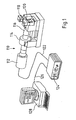
- Fig. 1 In principle, an arrangement is shown in which, according to the following explanations, an intrinsically rigid, planar carrier as the first conductor with strands such as cables or lines as an electrical second conductor are welded by means of ultrasound.
- the arrangement comprises an ultrasonic welding apparatus or machine 110, which conventionally comprises a converter 112, optionally a booster 114 and a sonotrode 116.
- the sonotrode 116 or a surface thereof are a multi-part counter electrode 118 - also called anvil - and a slider 120 associated with, as the DE-C-37 19 083 or the WO 95/10866 can be seen.
- the sonotrode 116 or their Surface, the counter electrode 118 and the slider 120 define a variable in cross-section compression space into which the first and second conductors to be welded are introduced.
- the converter 112 is connected via a line 122 to a generator 124, which in turn leads via a line 126 to a PC 128, via which a control of the welding processes takes place and entered into the welding parameters or cross-section or width of the first and second electrical conductors or can be retrieved from the corresponding stored values.
- a corresponding ultrasonic welding device whose power is designed for a cross-section of conductors which is smaller than the total cross-section of the second conductor to be welded onto the first conductor according to the invention.
- several second conductors are welded one after the other according to the invention with a first conductor. Characterized in that the second conductors are welded sequentially to the first conductor, each second conductor in each case, however, has a maximum cross-section, which is welded by the ultrasonic welding device in terms of performance, results in a total weld joint, which ensures a secure connection between the first and second conductors Minimization of contact resistance guaranteed.
- Fig. 2 is a section of the Fig. 1 to be taken ultrasonic welding device, wherein the compression chamber 10 is surrounded by a portion of the sonotrode 116, the two-part counter electrode 118 and the side shifter 120.
- the two-part anvil 118 consists of a carrier 12 displaceable along the sonotrode 116 and a crosshead 14 which is displaceable parallel to the boundary surface formed by the sonotrode 116.
- a first conductor 16 with an outer portion 18 is first introduced.
- the first conductor 16 is hereinafter referred to as a carrier or contact piece for reasons of simplicity.
- On the portion 18 of the carrier 16 is then stripped end of a strand 20 as a second electrical conductor placed.
- the compression chamber 10 is closed and the anvil 118 in the direction of the sonotrode 116 (arrow 22) adjusted to exert the required pressure on the parts to be welded, so the carrier 16 and the strand 20.
- the sonotrode 116 is excited in ultrasonic vibrations to perform the required welding operation.
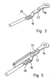
- the compression space 10 is opened and a connection is obtained between the carrier 16 and the strand 20, in the portion 18 of the carrier 16, as the Fig.
- the carrier 16 is adjusted to the compression space 10 such that the over a step from the portion 18 spaced portion 22 is located in the compression space 10.
- the section 22 extends parallel to the outer portion 18.
- a group of strands 24 is placed as a second electrical conductor in the compression space on the portion 22 in the embodiment, in the manner previously described a Perform welding.
- the result is a welded part, which is the Fig. 5 can be seen.
- the carrier 16 is welded in its sections 18, 22 each with a second electrical conductor or a group of second electrical conductors, namely with the strand 20 and the strand group 24.
- the total cross section of the second electrical conductor may be larger than usually electrical conductors can be welded to the ultrasonic welding device.
- Another advantage of the method according to the invention is that second conductors of different cross sections are welded successively to the first conductor so that optimal process monitoring can be carried out for the conductor cross sections to be welded in each case.
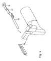
- the carrier or the contact piece 16 is again in Fig. 6 shown in perspective view. It can be seen that formed as an eyelet to be connected to a terminal front portion 26 and extending to this in parallel planes extending portions 18, 22. The same is clear from the illustrations of FIGS. 7 and 8 , In this case, in addition to the formed as an eyelet section 26, a further second electrical conductor to be welded.
- a variant of a corresponding contact piece is shown and provided with the reference numeral 28.
- the carrier or the contact piece 28 differs from the carrier 16 in that the sections 34, 36 to be welded together with strands 30, 32 are not only spaced apart from one another by steps, but also have different widths.
- the outer portion 36 is narrower than the middle portion 38, which in turn is narrower than the front or eyelet portion 40.
- contact piece 42 as a first electrical conductor has end so-called holding or Crimpfahnen 44, 46 which are bent after welding of second electrical conductors to the support 42 in the direction of the welded second electrical conductor by means of ultrasound, to an additional mechanical fixation enable. Furthermore, there is a possibility that a shrink tube is pushed over the weld to achieve an insulation that provides additional mechanical strength.
- first electrical conductor such as a contact piece, support or terminal
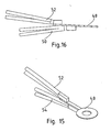
- second electrical conductors it is also possible for second electrical conductors to be welded on opposite sides of the first electrical conductor, wherein the second electrical conductor have been successively welded to the first electrical conductor according to the teaching of the invention. So you can see from the FIGS. 15 and 16 in that a contact piece 48 as the first electrical conductor is provided on its opposite sides, each with a second electrical conductor 50, 52 is connected, which in turn may consist of two or more strands welded together.
Description
Die Erfindung bezieht sich auf ein Verfahren zum Herstellen von zumindest einer Schweißverbindung zwischen zumindest einem eigensteifen flächigen Träger als ersten elektrischen Leiter und zumindest einem zweiten elektrischen Leiter, wie Litze, wobei die Leiter in einen von relativ zueinander verstellbaren Begrenzungselementen umgebenen Verdichtungsraum eingebracht und in diesem durch in Ultraschallschwingung versetzter eines der Begrenzungselemente bildender Sonotrode einer Ultraschall schweißvorrichtung verschweißt werden.The invention relates to a method for producing at least one welded joint between at least one intrinsically rigid sheet carrier as the first electrical conductor and at least one second electrical conductor, such as stranded wire, wherein the conductors are introduced into a compression space surrounded by relatively adjustable boundary elements and in this by ultrasonically displaced one of the boundary elements forming sonotrode an ultrasonic welding device to be welded.
Um auf einen Träger Litzen mittels Ultraschall aufzuschweißen, ist nach der
Der
Aus der
Aus der
Ebenfalls in Höhe und Breite verstellbare Verdichtungsräume von Ultraschallschweißvorrichtungen sind der
Die Leistungen der jeweils zum Einsatz gelangenden Ultraschalischweißvorrichtungen sind auf die maximalen Querschnitte der zu verschweißenden Leiter ausgelegt. Sollen üblicherweise z. B. Steuerleitungen mit einem Anschlussstück - auch Terminal genannt - verbunden werden, so ist die zum Einsatz gelangende Ultraschallschweißvorrichtung leistungsmäßig auf den Querschnitt der zu verschweißenden Steuerleitungen ausgelegt. Soll zusätzlich eine Masseleitung angeschlossen werden, so wird diese mit dem Terminal in konventioneller Technik durch Schrauben oder Stecken verbunden. Nachteilig einer entsprechenden Verbindung ist es, dass Übergangswiderstände auftreten können, die die Signale auf den Steuerleitungen stören können.The performance of each used reaching ultrasonic welding devices are designed for the maximum cross sections of the conductors to be welded. Should usually z. B. control lines with a connector - also called terminal - are connected, so the used reaching ultrasonic welding device is designed in terms of performance on the cross section of the control lines to be welded. If a ground line is also to be connected, it is connected to the terminal in conventional technology by screwing or plugging. A disadvantage of a corresponding connection is that contact resistances can occur which can disturb the signals on the control lines.
Aber auch dann, wenn die Leistung der Ultraschallschweißvorrichtung ausreichen sollte, auf einem Anschlussstück z. B. eine Masseleitung oder eine Batterieleitung zusammen mit einer Steuerleitung zu verschweißen, ergeben sich Nachteile dahingehend, dass eine hinreichend gute Prozessüberwachung nicht möglich ist; denn die Toleranzen, die beim Verschweißen von Leitern großer Querschnitte zulässig sind, sind häufig größer als die Querschnitte der Steuerleitungen, so dass in Folge dessen Kombinationsfehler auftreten können, die im Rahmen der Prozessüberwachung nicht feststellbar sind.But even if the power of the ultrasonic welding device should be sufficient on a connector z. B. to weld a ground line or a battery line together with a control line, there are disadvantages in that a sufficiently good process monitoring is not possible; because the tolerances that are allowed when welding conductors of large cross-sections are often greater than the cross sections of the control lines, so that as a result, combination errors can occur that are not detectable in the context of process monitoring.
Der vorliegenden Erfindung liegt die Aufgabe zu Grunde, ein Verfahren der eingangs genannten Art so weiterzubilden, dass im gewünschten Umfang ein erster Leiter mit zweiten Leitern mittels Ultraschallschweißens verbunden werden kann, wobei der Gesamtquerschnitt der mit dem ersten elektrischen Leiter zu verbindenden zweiten elektrischen Leiter gegebenenfalls größer sein soll als der üblicherweise mit der zum Einsatz gelangenden Ultraschallschweißvorrichtung Leiter verschweißt werden können. Auch soll die Möglichkeit bestehen, einen ersten Leiter mit zweiten Leitern großer und kleiner Querschnitte prozesssicher zu verbinden, so dass insbesondere unerwünschte Übergangswiderstände nicht auftreten.The present invention is based on the object, a method of the type mentioned in such a way that the desired extent, a first conductor with second conductors can be connected by means of ultrasonic welding, wherein the total cross-section the second electrical conductor to be connected to the first electrical conductor should optionally be larger than the conductor which can usually be welded to the ultrasonic welding apparatus used. It should also be possible to reliably connect a first conductor with second conductors of large and small cross-sections so that, in particular, undesirable contact resistances do not occur.
Erfindungsgemäß wird die Aufgabe im Wesentlichen dadurch gelöst, dass der erste Leiter in dem Verdichtungsraum nacheinander mit zwei oder mehreren zweiten Leitern verschweißt wird.According to the invention, the object is essentially achieved in that the first conductor in the compression space is welded successively to two or more second conductors.
Erfindungsgemäß wird die Möglichkeit eröffnet, einen ersten Leiter mit zweiten Leitern eines Gesamtquerschnitts zu verschweißen, der größer ist als üblicherweise mit der verwendeten Ultraschallschweißvorrichtung Leiterquerschnitte in einem Schweißvorgang verschweißt werden können. Ferner ist aufgrund der erfindungsgemäßen Lehre sichergestellt, dass mit einem ersten Leiter zweite Leiter großer und kleiner Querschnitte prozesssicher verschweißt werden können, da die zweiten Leiter großer Querschnitte nicht gleichzeitig mit den Leitern kleiner Querschnitte verschweißt werden, so dass eine gute Prozessüberwachung erfolgen kann. Durch diese Maßnahmen ist die Möglichkeit gegeben, im gewünschten Umfang zweite Leiter mit dem ersten Leiter zu verschweißen, ohne dass ein Wechsel der Ultraschallschweißvorrichtung erfolgen muss. Es können Ultraschallschweißvorrichtungen verwendet werden, die leistungsgemäß auf den jeweiligen mit dem ersten Leiter zu verbindenden einzelnen zweiten Leiter maximalen Querschnitts ausgelegt sind, wobei eine individuelle Prozessüberwachung unter Berücksichtigung der jeweiligen Leiterquerschnitte erfolgen kann.According to the invention, the possibility is opened up to weld a first conductor to second conductors of an overall cross-section, which is larger than is usually possible to weld conductor cross-sections in a welding operation with the ultrasonic welding device used. Furthermore, it is ensured on the basis of the teaching according to the invention that second conductors of large and small cross-sections can be reliably welded to a first conductor, since the second conductors of large cross-sections are not simultaneously welded to the conductors of smaller cross-sections, so that good process monitoring can take place. By these measures, the possibility is given to weld to the desired extent second conductor to the first conductor, without having to change the ultrasonic welding device. It is possible to use ultrasonic welding devices which, according to their performance, are designed for the individual second conductors of maximum cross-section to be connected to the first conductor, with individual process monitoring taking into account the respective conductor cross-sections.
Von Vorteil ist das Verfahren insbesondere dann, wenn zusätzlich zu bestehenden Verbindungen zwischen ersten und zweiten Leitern ein weiterer zweiter Leiter angeschlossen werden soll, ohne dass auf die herkömmlichen Verbindungsarten wie Schrauben oder Stecken zurückgegriffen werden muss. Somit ist eine sichere und gut leitende Verbindung gewährleistet, so dass unerwünschte Übergangswiderstände, die zu Störungen führen könnten, nicht auftreten. Es kann folglich ein problemloses Verbinden von Steuerleitungen und Massekabel bzw. Batterie mit einem Anschlussstück erfolgen, wie dies bei der Verkabelung insbesondere in der Kraftfahrzeugtechnik erfolgt.The method is particularly advantageous if, in addition to existing connections between first and second conductors, a further second conductor is to be connected, without having to resort to the conventional types of connection such as screws or connectors. Thus, a secure and well-conductive connection is guaranteed, so that undesirable contact resistance, which could lead to interference, do not occur. It can therefore easily connect control lines and ground cable or battery with a connector, as is done in the wiring especially in automotive technology.
Vorzugsweise ist vorgesehen, dass bei den aufeinander folgenden Schweißvorgängen der erste Leiter relativ zu dem Verdichtungsraum verstellt wird. Vorzugsweise wird der erste Leiter zu dem Verdichtungsraum verstellt. Es besteht aber auch die Möglichkeit, die Ultraschallschweißvorrichtung, d. h. den Verdichtungsraum entlang des ersten Leiters zu verstellen, um sodann sukzessiv die zweiten Leiter mit dem ersten Leiter zu verschweißen.It is preferably provided that in the successive welding operations, the first conductor is adjusted relative to the compression space. Preferably, the first conductor is adjusted to the compression space. But it is also possible, the ultrasonic welding device, d. H. to adjust the compression space along the first conductor to then successively weld the second conductor to the first conductor.
Sofern der Verdichtungsraum querschnittsmäßig im erforderlichen Umfang einstellbar ist, besteht die Möglichkeit, dass zweite Leiter übereinander auf dem ersten Leiter verschweißt werden. Auch insoweit erfolgt ein sukzessives Verschweißen, indem zunächst ein zweiter Leiter mit dem ersten Leiter verschweißt und sodann ein weiterer zweiter Leiter auf den mit dem ersten Leiter verschweißten zweiten Leiter verschweißt wird und so fort. Aber auch ein gleichzeitiges Verschweißen mehrerer zweiter Leiter mit einem ersten Leiter ist möglich, wobei zumindest ein weiterer zweiter Leiter in einem gesonderten Schweißprozess mit dem ersten Leiter verschweißt wird.If the compression space is adjustable in cross section to the required extent, there is the possibility that second conductors are welded one above the other on the first conductor. Also in this respect, a successive welding takes place by first welding a second conductor to the first conductor and then welding a second conductor onto the second conductor welded to the first conductor, and so on. But also a simultaneous welding of several second conductors with a first conductor is possible, wherein at least one further second conductor is welded in a separate welding process with the first conductor.
Bevorzugterweise sind die zweiten Leiter mit dem ersten Leiter und/oder Gruppen von zweiten Leitern in zueinander beabstandeten Bereichen verschweißt. Dabei besteht die Möglichkeit, dass der erste Leiter aus über Stufen zueinander beabstandeten Abschnitten besteht, wobei auf den entlang der Längsrichtung des ersten Leiters verlaufenden Abschnitten die zweiten Leiter verschweißt werden.Preferably, the second conductors are welded to the first conductor and / or groups of second conductors in spaced-apart regions. In this case, there is the possibility that the first conductor consists of sections which are spaced apart from one another by steps, the second conductors being welded on the sections running along the longitudinal direction of the first conductor.
Erfolgt das Verschweißen der zweiten Leiter auf dem ersten Leiter vorzugsweise in in dessen Längsrichtung zueinander beabstandeten Bereichen, so besteht auch die Möglichkeit, dass zwei zweite Leiter nebeneinander in einem quer zur Längsachse des ersten Leiters verlaufenden Bereich auf diesem verschweißt werden.If the welding of the second conductors on the first conductor is preferably carried out in regions spaced apart from one another in the longitudinal direction, it is also possible for two second conductors to be welded to one another next to one another in a region extending transversely to the longitudinal axis of the first conductor.
Das Schweißen von zweiten Leitern auf dem ersten Leiter auf gegenüberliegenden Seiten von diesem ist gleichfalls möglich.Welding of second conductors on the first conductor on opposite sides thereof is also possible.
Als ein erster zweiter Leiter können ein Massekabel oder Batteriekabel und als ein zweiter zweiter Leiter eine Steuerleitung mit dem ersten Leiter verschweißt werden.As a first second conductor, a ground wire or battery cable and, as a second second conductor, a control wire can be welded to the first wire.
Folglich kann die Ultraschallschweißvorrichtung leistungsmäßig derart ausgelegt werden, dass die mit dem ersten Leiter zu verschweißenden zweiten Leiter in einem Schweißvorgang insgesamt unverschweißbar wären.Consequently, the ultrasonic welding device can be designed in terms of performance such that the second conductors to be welded to the first conductor would be totally weldable in one welding operation.
Durch das nacheinander Verschweißen von zweiten Leitern mit dem ersten Leiter ergibt sich des Weiteren der Vorteil, dass die jeweils in einem Schweißvorgang zu verschweißenden zweiten Leiter mit dem ersten Leiter prozesssicher verbunden werden; denn würden z. B. Masse- bzw. Batterieleitungen, die einen Querschnitt zwischen 6 bis 35 mm2 bzw. 16 bis 70 mm2 aufweisen können, gleichzeitig mit Steuerleitungen, die einen Querschnitt zwischen 0,22 und 6 mm2 aufweisen können, verschweißt, würden die bezüglich der Masse- bzw. Batterieleitungen berücksichtigenden Toleranzen ein fehlerhaftes Verschweißen mit den Steuerleitungen überdecken, so dass fehlerhafte Verschweißungen auftreten könnten, ohne dass diese feststellbar sind.By successively welding second conductors to the first conductor, there is also the advantage that the second conductors to be welded in each case in a welding process are reliably connected to the first conductor; because z. As mass or battery lines, which may have a cross section between 6 to 35 mm 2 or 16 to 70 mm 2 , at the same time with control lines, which may have a cross section between 0.22 and 6 mm 2 , welded, the respect The tolerances taking into account the grounding or battery lines can mask faulty welding with the control lines, so that faulty welding could occur without them being detectable.
Des Weiteren sieht die Erfindung vor, dass bei Nutzung eines ersten Leiters mit von diesem ausgehenden Halteabschnitten wie Crimpfahnen während oder nach Verschweißen des letzten zweiten Leiters mit dem ersten Leiter die Halteabschnitte bei Ultraschallerregung der Sonotrode in Richtung der zweiten Leiter zum Fixieren dieser gebogen werden.Furthermore, the invention provides that when using a first conductor with this outgoing holding sections such as crimping during or after welding the last second conductor to the first conductor, the holding sections are bent in ultrasonic excitation of the sonotrode in the direction of the second conductor for fixing this.
Es besteht auch die Möglichkeit, den Schweißbereich nach Abschluss des Schweißens mit einem Schrumpfschlauch als Isolation bzw. als Isolation und mechanische Stabilisierung zu umgeben.It is also possible to surround the welding area after completion of welding with a shrink tube as insulation or as insulation and mechanical stabilization.
Erfindungsgemäß wird die Möglichkeit geschaffen, einen ersten Leiter mit mehreren zweiten Leitern zu verschweißen, ohne dass unerwünschte Übergangswiderstände auftreten, wobei der Gesamtquerschnitt der zweiten Leiter größer ist als üblicherweise mit der verwendeten Ultraschallschweißvorrichtung verschweißbar sind. Es sind problemlos große und kleine Querschnitte durch gestufte Schweißbereiche mit optimalen Schweißparametern zu verarbeiten.According to the invention, it is possible to weld a first conductor to a plurality of second conductors without undesirable contact resistances occurring, wherein the total cross section of the second conductor is larger than is usually weldable with the ultrasonic welding apparatus used. It is easy to process large and small cross sections through stepped welding areas with optimal welding parameters.
Weitere Einzelheiten, Vorteile und Merkmale der Erfindung ergeben sich nicht nur aus den Ansprüchen, den diesen zu entnehmenden Merkmalen - für sich und/oder in Kombination -, sondern auch aus der nachfolgenden Beschreibung von der Zeichnung zu entnehmenden bevorzugten Ausführungsbeispielen.For more details, advantages and features of the invention will become apparent not only from the claims, the features to be taken these features - alone and / or in combination - but also from the following description of the drawing to be taken preferred embodiments.
Es zeigen:
- Fig. 1
- eine Prinzipdarstellung einer Ultraschallschweißanordnung,
- Fig. 2
- einen Ausschnitt einer Ultraschallschweißvorrichtung mit zu verschweißenden ersten und zweiten Leitern,
- Fig. 3
- der mit dem zweiten Leiter verschweißte erste Leiter,
- Fig. 4
- einen Ausschnitt der Ultraschallschweißvorrichtung nach
Fig. 2 vor dem Verschweißen des ersten Leiters mit einem weiteren zweiten Leiter, - Fig. 5
- der mit zwei zweiten Leitern verschweißte erste Leiter,
- Fig. 6
- eine perspektivische Darstellung des den
Fig. 2 bis 4 zu entnehmenden ersten Leiters, - Fig. 7
- eine Draufsicht des zweiten Leiters gemäß
Fig. 6 , - Fig. 8
- eine Seitenansicht des zweiten Leiters gemäß
Fig. 6 und 7 , - Fig. 9
- eine Draufsicht auf eine weitere Ausführungsform eines zweiten Leiters,
- Fig. 10
- der erste Leiter gemäß
Fig. 9 , der mit zwei zweiten Leitern verschweißt ist, - Fig. 11
- die ersten und zweiten Leiter gemäß
Fig. 10 in Seitenansicht, - Fig. 12
- eine weitere Ausführungsform eines ersten Leiters,
- Fig. 13
- der erste Leiter gemäß
Fig. 12 in Seitenansicht, - Fig. 14
- der erste Leiter gemäß
Fig. 12 und 13 in Draufsicht, - Fig. 15
- eine weitere Ausfühnngsform eines ersten Leiters, der mit zwei zweiten Leitern verschweißt ist, und
- Fig. 16
- der mit den zweiten Leitern verschweißte erste Leiter gemäß
Fig. 15 in Seitenansicht.
- Fig. 1
- a schematic diagram of an ultrasonic welding arrangement,
- Fig. 2
- a detail of an ultrasonic welding device to be welded with first and second conductors,
- Fig. 3
- the first conductor welded to the second conductor,
- Fig. 4
- a section of the ultrasonic welding device according to
Fig. 2 before welding the first conductor to another second conductor, - Fig. 5
- the first conductor welded to two second conductors,
- Fig. 6
- a perspective view of the
Fig. 2 to 4 to be removed first conductor, - Fig. 7
- a plan view of the second conductor according to
Fig. 6 . - Fig. 8
- a side view of the second conductor according to
6 and 7 . - Fig. 9
- a top view of another embodiment of a second conductor,
- Fig. 10
- the first conductor according to
Fig. 9 which is welded to two second conductors, - Fig. 11
- the first and second conductors according to
Fig. 10 in side view, - Fig. 12
- another embodiment of a first conductor,
- Fig. 13
- the first conductor according to
Fig. 12 in side view, - Fig. 14
- the first conductor according to
FIGS. 12 and 13 in plan view, - Fig. 15
- another Ausfühnngsform a first conductor, which is welded to two second conductors, and
- Fig. 16
- the first conductor welded to the second conductors according to
Fig. 15 in side view.
In
Der Konverter 112 ist über eine Leitung 122 mit einem Generator 124 verbunden, der seinerseits über eine Leitung 126 zu einem PC 128 führt, über den eine Steuerung der Schweißprozesse erfolgt und in die Schweißparameter bzw. Querschnitt bzw. Breite der ersten und zweiten elektrischen Leiter eingegeben bzw. von der entsprechend abgespeicherte Werte abgerufen werden können.The
Erfindungsgemäß wird eine entsprechende Ultraschallschweißvorrichtung benutzt, deren Leistung auf einen Querschnitt von Leitern ausgelegt ist, der kleiner als der Gesamtquerschnitt der gemäß der erfindungsgemäßen Lehre auf den ersten Leiter zu verschweißenden zweiten Leiter ist. Hierzu werden nach der Erfindung mit einem ersten Leiter mehrere zweite Leiter nacheinander verschweißt. Dadurch, dass die zweiten Leiter nacheinander mit dem ersten Leiter verschweißt werden, jeder zweite Leiter jeweils für sich jedoch einen maximalen Querschnitt aufweist, der leistungsmäßig von der Ultraschallschweißvorrichtung verschweißbar ist, ergibt sich eine Gesamtschweißverbindung, die eine sichere Verbindung zwischen den ersten und zweiten Leitern bei Minimierung des Übergangswiderstandes gewährleistet.According to the invention, a corresponding ultrasonic welding device is used whose power is designed for a cross-section of conductors which is smaller than the total cross-section of the second conductor to be welded onto the first conductor according to the invention. For this purpose, several second conductors are welded one after the other according to the invention with a first conductor. Characterized in that the second conductors are welded sequentially to the first conductor, each second conductor in each case, however, has a maximum cross-section, which is welded by the ultrasonic welding device in terms of performance, results in a total weld joint, which ensures a secure connection between the first and second conductors Minimization of contact resistance guaranteed.
In
In den geöffneten Verdichtungsraum 10 wird zunächst ein erster Leiter 16 mit einem äußeren Abschnitt 18 eingebracht. Der erste Leiter 16 wird nachstehend aus Gründen der Vereinfachung als Träger oder Kontaktstück bezeichnet. Auf den Abschnitt 18 des Trägers 16 wird sodann abisoliertes Ende einer Litze 20 als zweiter elektrischer Leiter gelegt. Sodann wird der Verdichtungsraum 10 geschlossen und der Amboss 118 in Richtung der Sonotrode 116 (Pfeil 22) verstellt, um den erforderlichen Druck auf die zu verschweißenden Teile, also den Träger 16 und die Litze 20 auszuüben. Gleichzeitig ist die Sonotrode 116 in Ultraschallschwingungen erregt, um den erforderlichen Schweißvorgang durchzuführen. Nach dem Schweißen wird der Verdichtungsraum 10 geöffnet und man erhält eine Verbindung zwischen dem Träger 16 und der Litze 20, und zwar in dem Abschnitt 18 des Trägers 16, wie der
Ultraschallschweißvorrichtungen mit einer Leistung bis 3 kW ermöglichen z. B. das Verschweißen von Litzen mit einem Gesamtquerschnitt von 35 mm2. Aufgrund der erfindungsgemäßen Lehre können mit dem ersten Leiter zweite Leiter verschweißt werden, die insgesamt einen größeren Querschnitt aufweisen. Voraussetzung hiefür ist jedoch, dass in jedem Schweißvorgang mit dem ersten Leiter zweite Leiter mit einem maximalen Gesamtquerschnitt verschweißt werden, der gleich oder kleiner als 35 mm2 ist, sofern man die zuvor angegebenen Werte zugrunde legt.Ultrasonic welding devices with a power up to 3 kW allow z. B. the welding of strands with a total cross section of 35 mm 2 . Due to the teaching of the invention, second conductors can be welded to the first conductor, which overall have a larger cross-section. The prerequisite for this, however, is that, in each welding operation, second conductors are welded to the first conductor with a maximum total cross-section which is equal to or less than 35 mm 2 , if the values given above are used as a basis.
Vorteil des erfindungsgemäßen Verfahrens ist auch, dass mit dem ersten Leiter zweite Leiter unterschiedlicher Querschnitte nacheinander verschweißt werden, so dass für die jeweils zu verschweißenden Leiterquerschnitte eine optimale Prozessüberwachung erfolgen kann.Another advantage of the method according to the invention is that second conductors of different cross sections are welded successively to the first conductor so that optimal process monitoring can be carried out for the conductor cross sections to be welded in each case.
Der Träger bzw. das Kontaktstück 16 ist noch einmal in
In den
Ein den
Ist in den zuvor erläuterten Ausführungsbeispielen ein erster elektrischer Leiter wie Kontaktstück, Träger oder Terminal jeweils nur auf einer Seite mit mehreren elektrischen zweiten Leitern verbunden, so besteht auch die Möglichkeit, dass zweite elektrische Leiter auf gegenüberliegenden Seiten des ersten elektrischen Leiters angeschweißt werden, wobei die zweiten elektrischen Leiter nacheinander mit dem ersten elektrischen Leiter entsprechend der erfindungsgemäßen Lehre verschweißt worden sind. So erkennt man aus den
Claims (13)
- A method for producing at least one welded joint between at least one inherently rigid flat support as first electrical conductor (16, 28, 42, 48) and at least a second electrical conductor (20, 24, 30, 32, 50, 52), such as strand, said conductors are inserted into a compaction space (10) surrounded by delimiting elements (116, 118, 120) which are displaceable relative to each another, and are welded in said compaction space by a sonotrode (116) of an ultrasonic welding device (110) excitable to ultrasonic oscillation, said sonotrode forming one of the delimiting elements,
characterized in
that the first conductor (16, 28, 42, 48) is welded in the compaction space (10) successively to two or several second conductors (20, 24, 30, 32, 50, 52). - The method according to claim 1,
characterized in
that during the successive welding processes, the first conductor (16, 28, 42, 48) is displaced relative to the compaction space (10). - A method according to claim 1 or 2,
characterized in
that the first conductor (16, 28, 42, 48) is displaced to the compaction space (10). - A method according to one of the preceding claims,
characterized in
that to the first conductor (16, 28, 42, 48) are welded second conductors (20, 24, 30, 32, 50, 52) having equal and/or different cross sections. - A method according to one of the preceding claims,
characterized in
that second conductors (30, 32) are welded on top of one another onto the first conductor (28). - A method according to one of the preceding claims,
characterized in
that the second conductors (30, 32) are welded to the first conductor (28) in areas (36, 38) that are spaced apart from one another. - A method according to one of the preceding claims,
characterized in
that the second conductors (30, 32) are welded on areas (36, 38) of the first conductor (28) that run in different planes from one another. - A method according to one of the preceding claims,
characterized in
that the second conductors (30, 32) are welded in areas (36, 38) of the first conductor (28) that extend over levels that are spaced apart from one another and parallel to one another. - A method according to one of the preceding claims,
characterized in
that welded to the first conductor (16, 28, 42, 48) are a grounding cable or battery cable as a first second conductor, and a control cable as a second second conductor. - A method according to one of the preceding claims,
characterized in
that at least two second conductors are welded in parallel to the first conductor (16, 28, 42, 48) in an area that runs crosswise to its longitudinal axis. - A method according to one of the preceding claims,
characterized in
that to the first conductor (16, 28, 42, 48) are welded successively a group of second conductors and a second conductor or a group of second conductors. - A method according to one of the preceding claims, whereby from the first conductor (42) extend holding sections such as crimp lugs (44, 46),
characterized in
that during or after welding of the last second conductor to the first conductor (40) the holding sections (44, 46) are bend towards the second conductors by ultrasonic excitation of the sonotrode, in order to secure them. - A method according to one of the preceding claims,
characterized in
that the ultrasonic welding device (110) has such a power output that second conductors (20, 24, 30, 32, 50, 52) to be welded to the first conductor (16, 28, 42, 48) are not weldable altogether or are not process reliable weldable.
Priority Applications (1)
| Application Number | Priority Date | Filing Date | Title |
|---|---|---|---|
| PL06818252T PL1960151T3 (en) | 2005-10-10 | 2006-10-07 | Method for production of a welded connection between electrical conductors by means of an ultrasound welding method |
Applications Claiming Priority (2)
| Application Number | Priority Date | Filing Date | Title |
|---|---|---|---|
| DE102005048368A DE102005048368B3 (en) | 2005-10-10 | 2005-10-10 | Method for producing a welded connection between electrical conductors |
| PCT/EP2006/009715 WO2007042235A1 (en) | 2005-10-10 | 2006-10-07 | Method for production of a welded connection between electrical conductors by means of an ultrasound welding method |
Publications (2)
| Publication Number | Publication Date |
|---|---|
| EP1960151A1 EP1960151A1 (en) | 2008-08-27 |
| EP1960151B1 true EP1960151B1 (en) | 2013-07-24 |
Family
ID=37622319
Family Applications (1)
| Application Number | Title | Priority Date | Filing Date |
|---|---|---|---|
| EP06818252.6A Not-in-force EP1960151B1 (en) | 2005-10-10 | 2006-10-07 | Method for production of a welded connection between electrical conductors by means of an ultrasound welding method |
Country Status (9)
| Country | Link |
|---|---|
| US (1) | US8047420B2 (en) |
| EP (1) | EP1960151B1 (en) |
| JP (1) | JP5291465B2 (en) |
| KR (1) | KR101394099B1 (en) |
| CN (1) | CN101282815B (en) |
| BR (1) | BRPI0617201B1 (en) |
| DE (1) | DE102005048368B3 (en) |
| PL (1) | PL1960151T3 (en) |
| WO (1) | WO2007042235A1 (en) |
Cited By (2)
| Publication number | Priority date | Publication date | Assignee | Title |
|---|---|---|---|---|
| DE102019003141B3 (en) | 2019-05-03 | 2020-06-10 | NovaTec GmbH lnnovative Technologie | Device and method for connecting strands to contact plates by ultrasonic welding |
| EP3050163B1 (en) | 2013-09-24 | 2020-08-26 | ElringKlinger AG | Method for establishing an electrically conductive connection between an electrical line and an electrically conductive component |
Families Citing this family (32)
| Publication number | Priority date | Publication date | Assignee | Title |
|---|---|---|---|---|
| DE102008049377B4 (en) * | 2008-09-27 | 2023-10-12 | Kromberg & Schubert Gmbg & Co. Kg | Ground contact assembly for placement on a ground bolt |
| JP5654242B2 (en) * | 2010-01-18 | 2015-01-14 | 矢崎総業株式会社 | Electrical wire terminal treatment method |
| DE102011014801B4 (en) | 2011-03-23 | 2019-08-08 | Audi Ag | Method for welding conductors |
| JP5913851B2 (en) * | 2011-07-20 | 2016-04-27 | 矢崎総業株式会社 | Wire connection method |
| FR2981214B1 (en) * | 2011-10-07 | 2014-09-12 | Leoni Wiring Systems France | CONNECTING TWO ELECTRICAL CONDUCTORS TO AN ELECTRICAL BODY ELEMENT |
| DE102013212331A1 (en) | 2013-04-04 | 2014-10-09 | Telsonic Holding Ag | Method of connecting a tubular cable lug to a strand made of aluminum |
| JP6056639B2 (en) * | 2013-05-07 | 2017-01-11 | 株式会社オートネットワーク技術研究所 | Terminal, electric wire with terminal, and manufacturing method of electric wire with terminal |
| DE102013106349A1 (en) * | 2013-05-13 | 2014-11-13 | Schunk Sonosystems Gmbh | Method for determining the degree of compaction of a node |
| DE102013107637A1 (en) | 2013-07-18 | 2015-01-22 | Schunk Sonosystems Gmbh | Method for producing a knot by welding |
| US10189118B2 (en) * | 2016-06-06 | 2019-01-29 | GM Global Technology Operations LLC | Method and apparatus for evaluating an ultrasonic weld junction |
| EP3260229A1 (en) * | 2016-06-22 | 2017-12-27 | Delphi Technologies, Inc. | Clamping system for an ultrasonic welding apparatus and the use thereof |
| DE102016214227B3 (en) * | 2016-08-02 | 2017-12-07 | Schunk Sonosystems Gmbh | Apparatus and method for producing a tested welded joint |
| JP6607405B2 (en) * | 2016-10-11 | 2019-11-20 | 住友電装株式会社 | Conductive path |
| JP6852784B2 (en) * | 2017-03-16 | 2021-03-31 | 三菱電機株式会社 | Plate-shaped solder manufacturing equipment and its manufacturing method |
| CN110891726B (en) * | 2017-04-04 | 2021-08-24 | 库利克和索夫工业公司 | Ultrasonic welding system and method of use |
| DE102017114182B3 (en) * | 2017-06-27 | 2018-09-13 | Schunk Sonosystems Gmbh | Method and arrangement for the electrically conductive connection of conductors |
| DE102017119809A1 (en) * | 2017-08-29 | 2019-02-28 | Schunk Sonosystems Gmbh | Method for welding electrical conductors and ultrasonic metal welding device |
| US11322866B2 (en) | 2017-11-03 | 2022-05-03 | Elco Enterprises, Inc. | Ultrasonic welded cable for a welding system |
| DE102017131371A1 (en) * | 2017-12-28 | 2019-07-04 | Te Connectivity Germany Gmbh | Mechanical connection element, electrical contact device and electrical connector |
| DE102018108979A1 (en) | 2018-04-16 | 2019-10-17 | Branson Ultraschall Niederlassung Der Emerson Technologies Gmbh & Co. Ohg | A vibration welding apparatus, method of joining at least two elongate members by vibration welding, and a method of manufacturing the vibration welding apparatus |
| DE102018109837B4 (en) * | 2018-04-24 | 2019-11-07 | Te Connectivity Germany Gmbh | A conduit arrangement and method for producing a conduit arrangement |
| DE102018119844B4 (en) * | 2018-07-26 | 2022-10-06 | Auto-Kabel Management Gmbh | Electrical connection and method of making an electrical connection |
| DE102018127729A1 (en) * | 2018-11-07 | 2020-05-07 | Auto-Kabel Management Gmbh | Process for producing a connector for electrical systems, connector and connection of a connector with a cable |
| JP2022510882A (en) | 2018-11-28 | 2022-01-28 | クリック アンド ソッファ インダストリーズ、インク. | Ultrasonic welding system and how to use the system |
| EP3663008B1 (en) | 2018-12-06 | 2023-10-25 | Telsonic Holding AG | Ultrasonic oscillator, ultrasonic oscillation system and method for operating the same |
| WO2021089123A1 (en) * | 2019-11-05 | 2021-05-14 | Schunk Sonosystems Gmbh | Ultrasonic welding device having movable stop element |
| KR20220051267A (en) * | 2019-11-07 | 2022-04-26 | 슈운크 소노시스템스 게엠바하 | Ultrasonic Welding Apparatus with Cooling for Oscillator Apparatus |
| US11515678B2 (en) * | 2020-01-09 | 2022-11-29 | Aptiv Technologies Limited | Splice connector |
| US11827372B2 (en) | 2020-05-15 | 2023-11-28 | Pratt & Whitney Canada Corp. | Engine characteristics matching |
| US11958622B2 (en) | 2020-05-15 | 2024-04-16 | Pratt & Whitney Canada Corp. | Protection functions |
| US11794917B2 (en) | 2020-05-15 | 2023-10-24 | Pratt & Whitney Canada Corp. | Parallel control loops for hybrid electric aircraft |
| WO2023006210A1 (en) | 2021-07-29 | 2023-02-02 | Schunk Sonosystems Gmbh | Ultrasonic welding method and ultrasonic welding part |
Citations (2)
| Publication number | Priority date | Publication date | Assignee | Title |
|---|---|---|---|---|
| US5827081A (en) * | 1995-05-18 | 1998-10-27 | Niles Parts Co., Ltd. | Rotary connector apparatus |
| US20050095887A1 (en) * | 1998-05-12 | 2005-05-05 | Yazaki Corporation | Method of manufacturing connector for flat cable, connector for flat cable, and applying member for applying ultrasonic vibrations to be used for the same method |
Family Cites Families (19)
| Publication number | Priority date | Publication date | Assignee | Title |
|---|---|---|---|---|
| JPS5385389A (en) * | 1977-01-05 | 1978-07-27 | Hitachi Ltd | Connecting conductor |
| JPS5847833B2 (en) * | 1979-07-18 | 1983-10-25 | 三菱電機株式会社 | Connection wire manufacturing equipment |
| DE3017364C2 (en) * | 1980-05-07 | 1982-12-02 | Niebuhr Mikroschweißtechnik GmbH, 8752 Goldbach | Method and device for connecting an electrical conductor to a plug |
| DE3338757A1 (en) | 1983-10-25 | 1985-05-02 | Siemens AG, 1000 Berlin und 8000 München | Method for producing non-detachable electrical connections of wires and/or braided cables to one another, and wires and/or braided cables to connecting elements, by means of ultrasound welding, and ultrasound welding device used for this purpose, and associated ultrasound connectors |
| DE3335254A1 (en) | 1983-09-29 | 1985-04-18 | Schunk Ultraschalltechnik Gmbh, 8750 Aschaffenburg | CONNECTING DEVICE COMPRESS ELECTRICAL LADDER |
| DE3437749A1 (en) * | 1984-10-15 | 1986-04-17 | Schunk Ultraschalltechnik GmbH, 6301 Wettenberg | Method and device for compressing electrical conductors, and mechanical and electrically conductive connection of these conductors on a support |
| JPS62201462U (en) * | 1986-06-14 | 1987-12-22 | ||
| JPS63129973U (en) * | 1987-02-17 | 1988-08-25 | ||
| DE3719083C2 (en) * | 1987-06-06 | 1994-04-28 | Stapla Ultraschalltechnik Gmbh | Method for connecting electrical conductors and device for carrying out the method |
| DE4335108C1 (en) * | 1993-10-14 | 1995-01-05 | Schunk Ultraschalltechnik Gmbh | Method and device for compacting and subsequent welding of electrical conductors |
| JPH09139238A (en) * | 1995-11-13 | 1997-05-27 | Sumitomo Wiring Syst Ltd | Electric wire connecting method |
| DE19906088A1 (en) * | 1998-08-01 | 2000-02-03 | Welcker F | Battery pole connection cable |
| JP5008787B2 (en) * | 2000-04-10 | 2012-08-22 | パナソニック株式会社 | Battery electrode and manufacturing method thereof |
| US6299052B1 (en) * | 2000-06-28 | 2001-10-09 | American Technology, Inc. | Anti-slide splice welder |
| JP4013691B2 (en) * | 2002-07-31 | 2007-11-28 | 住友電装株式会社 | Flexible flat cable connection method and ultrasonic welding machine |
| JP2005085560A (en) * | 2003-09-08 | 2005-03-31 | Showa Electric Wire & Cable Co Ltd | Litz wire coil |
| MXPA06004855A (en) * | 2003-10-29 | 2006-07-06 | Schunk Ultraschalltechnik Gmbh | Method for welding conductors. |
| BRPI0513737B1 (en) * | 2004-07-23 | 2015-01-13 | Schunk Ultraschalltechnik Gmbh | PROCESS FOR PRODUCTION OF A WELDING UNION BETWEEN ELECTRICAL CONDUCTORS |
| DE102004044480A1 (en) * | 2004-07-23 | 2006-02-16 | Schunk Ultraschalltechnik Gmbh | Method for welding ultrasonic litz wire involving a preferably cuboid carrier inserted in a compression space which on welding is decreased in diameter useful for useful for ultrasonic and resistance welding of joints |
-
2005
- 2005-10-10 DE DE102005048368A patent/DE102005048368B3/en not_active Expired - Fee Related
-
2006
- 2006-10-07 KR KR1020087008613A patent/KR101394099B1/en active IP Right Grant
- 2006-10-07 BR BRPI0617201-6A patent/BRPI0617201B1/en not_active IP Right Cessation
- 2006-10-07 JP JP2008533949A patent/JP5291465B2/en not_active Expired - Fee Related
- 2006-10-07 CN CN2006800377073A patent/CN101282815B/en not_active Expired - Fee Related
- 2006-10-07 WO PCT/EP2006/009715 patent/WO2007042235A1/en active Application Filing
- 2006-10-07 EP EP06818252.6A patent/EP1960151B1/en not_active Not-in-force
- 2006-10-07 PL PL06818252T patent/PL1960151T3/en unknown
- 2006-10-07 US US12/088,016 patent/US8047420B2/en not_active Expired - Fee Related
Patent Citations (2)
| Publication number | Priority date | Publication date | Assignee | Title |
|---|---|---|---|---|
| US5827081A (en) * | 1995-05-18 | 1998-10-27 | Niles Parts Co., Ltd. | Rotary connector apparatus |
| US20050095887A1 (en) * | 1998-05-12 | 2005-05-05 | Yazaki Corporation | Method of manufacturing connector for flat cable, connector for flat cable, and applying member for applying ultrasonic vibrations to be used for the same method |
Cited By (2)
| Publication number | Priority date | Publication date | Assignee | Title |
|---|---|---|---|---|
| EP3050163B1 (en) | 2013-09-24 | 2020-08-26 | ElringKlinger AG | Method for establishing an electrically conductive connection between an electrical line and an electrically conductive component |
| DE102019003141B3 (en) | 2019-05-03 | 2020-06-10 | NovaTec GmbH lnnovative Technologie | Device and method for connecting strands to contact plates by ultrasonic welding |
Also Published As
| Publication number | Publication date |
|---|---|
| BRPI0617201A2 (en) | 2011-07-19 |
| WO2007042235A1 (en) | 2007-04-19 |
| BRPI0617201B1 (en) | 2015-04-14 |
| US8047420B2 (en) | 2011-11-01 |
| DE102005048368B3 (en) | 2007-05-03 |
| CN101282815B (en) | 2013-03-27 |
| EP1960151A1 (en) | 2008-08-27 |
| KR101394099B1 (en) | 2014-05-27 |
| JP2009512124A (en) | 2009-03-19 |
| KR20080072821A (en) | 2008-08-07 |
| CN101282815A (en) | 2008-10-08 |
| JP5291465B2 (en) | 2013-09-18 |
| PL1960151T3 (en) | 2013-12-31 |
| US20080265004A1 (en) | 2008-10-30 |
Similar Documents
| Publication | Publication Date | Title |
|---|---|---|
| EP1960151B1 (en) | Method for production of a welded connection between electrical conductors by means of an ultrasound welding method | |
| EP1771274B1 (en) | Method for producing a welded joint between electrical wires with a support | |
| EP3050163B1 (en) | Method for establishing an electrically conductive connection between an electrical line and an electrically conductive component | |
| EP2978085B1 (en) | Method to electrical connection of wires | |
| EP2609655B1 (en) | Method and device for connecting an electrical conductor to an electrical contact part | |
| DE102008003961B4 (en) | Apparatus and method for crimping a fitting | |
| EP3069419B1 (en) | Device for welding electric conductors | |
| DE102008045751A1 (en) | Apparatus and method for compacting welding | |
| EP2605881A2 (en) | Method and arrangement for welding electrical conductors | |
| WO2019042909A1 (en) | Method for welding electrical conductors by means of ultrasound and ultrasonic metal welding device | |
| WO2021094224A1 (en) | Battery with a plurality of battery cells and method for producing a battery | |
| EP3698441B1 (en) | Device and method for ultrasound connection of electrical conductors | |
| DE102004044480A1 (en) | Method for welding ultrasonic litz wire involving a preferably cuboid carrier inserted in a compression space which on welding is decreased in diameter useful for useful for ultrasonic and resistance welding of joints | |
| DE202004010775U1 (en) | Device for welding electric conductors using ultrasound welding arrangement has sonotrode body having welding surfaces with a concave progression with respect to a counter electrode | |
| EP1530271B1 (en) | Apparatus for welding the strands of wires | |
| EP3631912B1 (en) | Contacting-making method for enamel-insulated conductors | |
| EP3258550A1 (en) | Device and method for crimping of fastener elements and crimped connection | |
| EP3474391B1 (en) | Method for joining at least two multi-strand leads by means of ultrasound | |
| DE102022117760B3 (en) | Electrical contact element | |
| WO2018060198A1 (en) | Method and apparatus for electrically connecting two metal conductors | |
| EP3076483B1 (en) | Electrical contact system and method for producing such electrical contact system | |
| WO2005123322A1 (en) | Ultrasound welding device | |
| WO2023006210A1 (en) | Ultrasonic welding method and ultrasonic welding part | |
| DE102021130526A1 (en) | Method and use of a device for welding a stranded wire to a contact element | |
| WO2022022833A1 (en) | Method for multi-stage welding of nodes by means of an ultrasonic welding device, and corresponding conductor bundle |
Legal Events
| Date | Code | Title | Description |
|---|---|---|---|
| PUAI | Public reference made under article 153(3) epc to a published international application that has entered the european phase |
Free format text: ORIGINAL CODE: 0009012 |
|
| 17P | Request for examination filed |
Effective date: 20080509 |
|
| AK | Designated contracting states |
Kind code of ref document: A1 Designated state(s): AT BE BG CH CY CZ DE DK EE ES FI FR GB GR HU IE IS IT LI LT LU LV MC NL PL PT RO SE SI SK TR |
|
| 17Q | First examination report despatched |
Effective date: 20090623 |
|
| DAX | Request for extension of the european patent (deleted) | ||
| GRAP | Despatch of communication of intention to grant a patent |
Free format text: ORIGINAL CODE: EPIDOSNIGR1 |
|
| GRAS | Grant fee paid |
Free format text: ORIGINAL CODE: EPIDOSNIGR3 |
|
| GRAP | Despatch of communication of intention to grant a patent |
Free format text: ORIGINAL CODE: EPIDOSNIGR1 |
|
| GRAA | (expected) grant |
Free format text: ORIGINAL CODE: 0009210 |
|
| INTG | Intention to grant announced |
Effective date: 20130606 |
|
| AK | Designated contracting states |
Kind code of ref document: B1 Designated state(s): AT BE BG CH CY CZ DE DK EE ES FI FR GB GR HU IE IS IT LI LT LU LV MC NL PL PT RO SE SI SK TR |
|
| REG | Reference to a national code |
Ref country code: GB Ref legal event code: FG4D Free format text: NOT ENGLISH |
|
| REG | Reference to a national code |
Ref country code: CH Ref legal event code: EP |
|
| REG | Reference to a national code |
Ref country code: AT Ref legal event code: REF Ref document number: 623106 Country of ref document: AT Kind code of ref document: T Effective date: 20130815 |
|
| REG | Reference to a national code |
Ref country code: IE Ref legal event code: FG4D Free format text: LANGUAGE OF EP DOCUMENT: GERMAN |
|
| REG | Reference to a national code |
Ref country code: DE Ref legal event code: R096 Ref document number: 502006013060 Country of ref document: DE Effective date: 20130919 |
|
| REG | Reference to a national code |
Ref country code: RO Ref legal event code: EPE Ref country code: CH Ref legal event code: NV Representative=s name: LUCHS AND PARTNER PATENTANWAELTE, CH |
|
| REG | Reference to a national code |
Ref country code: NL Ref legal event code: VDEP Effective date: 20130724 |
|
| REG | Reference to a national code |
Ref country code: LT Ref legal event code: MG4D |
|
| REG | Reference to a national code |
Ref country code: PL Ref legal event code: T3 |
|
| REG | Reference to a national code |
Ref country code: SK Ref legal event code: T3 Ref document number: E 15030 Country of ref document: SK |
|
| PG25 | Lapsed in a contracting state [announced via postgrant information from national office to epo] |
Ref country code: LT Free format text: LAPSE BECAUSE OF FAILURE TO SUBMIT A TRANSLATION OF THE DESCRIPTION OR TO PAY THE FEE WITHIN THE PRESCRIBED TIME-LIMIT Effective date: 20130724 Ref country code: IS Free format text: LAPSE BECAUSE OF FAILURE TO SUBMIT A TRANSLATION OF THE DESCRIPTION OR TO PAY THE FEE WITHIN THE PRESCRIBED TIME-LIMIT Effective date: 20131124 Ref country code: PT Free format text: LAPSE BECAUSE OF FAILURE TO SUBMIT A TRANSLATION OF THE DESCRIPTION OR TO PAY THE FEE WITHIN THE PRESCRIBED TIME-LIMIT Effective date: 20131125 Ref country code: CY Free format text: LAPSE BECAUSE OF FAILURE TO SUBMIT A TRANSLATION OF THE DESCRIPTION OR TO PAY THE FEE WITHIN THE PRESCRIBED TIME-LIMIT Effective date: 20130626 Ref country code: SE Free format text: LAPSE BECAUSE OF FAILURE TO SUBMIT A TRANSLATION OF THE DESCRIPTION OR TO PAY THE FEE WITHIN THE PRESCRIBED TIME-LIMIT Effective date: 20130724 |
|
| PG25 | Lapsed in a contracting state [announced via postgrant information from national office to epo] |
Ref country code: SI Free format text: LAPSE BECAUSE OF FAILURE TO SUBMIT A TRANSLATION OF THE DESCRIPTION OR TO PAY THE FEE WITHIN THE PRESCRIBED TIME-LIMIT Effective date: 20130724 Ref country code: FI Free format text: LAPSE BECAUSE OF FAILURE TO SUBMIT A TRANSLATION OF THE DESCRIPTION OR TO PAY THE FEE WITHIN THE PRESCRIBED TIME-LIMIT Effective date: 20130724 Ref country code: GR Free format text: LAPSE BECAUSE OF FAILURE TO SUBMIT A TRANSLATION OF THE DESCRIPTION OR TO PAY THE FEE WITHIN THE PRESCRIBED TIME-LIMIT Effective date: 20131025 Ref country code: NL Free format text: LAPSE BECAUSE OF FAILURE TO SUBMIT A TRANSLATION OF THE DESCRIPTION OR TO PAY THE FEE WITHIN THE PRESCRIBED TIME-LIMIT Effective date: 20130724 Ref country code: LV Free format text: LAPSE BECAUSE OF FAILURE TO SUBMIT A TRANSLATION OF THE DESCRIPTION OR TO PAY THE FEE WITHIN THE PRESCRIBED TIME-LIMIT Effective date: 20130724 |
|
| PG25 | Lapsed in a contracting state [announced via postgrant information from national office to epo] |
Ref country code: CY Free format text: LAPSE BECAUSE OF FAILURE TO SUBMIT A TRANSLATION OF THE DESCRIPTION OR TO PAY THE FEE WITHIN THE PRESCRIBED TIME-LIMIT Effective date: 20130724 |
|
| BERE | Be: lapsed |
Owner name: SCHUNK SONOSYSTEMS G.M.B.H. Effective date: 20131031 |
|
| PG25 | Lapsed in a contracting state [announced via postgrant information from national office to epo] |
Ref country code: DK Free format text: LAPSE BECAUSE OF FAILURE TO SUBMIT A TRANSLATION OF THE DESCRIPTION OR TO PAY THE FEE WITHIN THE PRESCRIBED TIME-LIMIT Effective date: 20130724 Ref country code: EE Free format text: LAPSE BECAUSE OF FAILURE TO SUBMIT A TRANSLATION OF THE DESCRIPTION OR TO PAY THE FEE WITHIN THE PRESCRIBED TIME-LIMIT Effective date: 20130724 |
|
| PG25 | Lapsed in a contracting state [announced via postgrant information from national office to epo] |
Ref country code: IT Free format text: LAPSE BECAUSE OF FAILURE TO SUBMIT A TRANSLATION OF THE DESCRIPTION OR TO PAY THE FEE WITHIN THE PRESCRIBED TIME-LIMIT Effective date: 20130724 Ref country code: ES Free format text: LAPSE BECAUSE OF FAILURE TO SUBMIT A TRANSLATION OF THE DESCRIPTION OR TO PAY THE FEE WITHIN THE PRESCRIBED TIME-LIMIT Effective date: 20130724 Ref country code: MC Free format text: LAPSE BECAUSE OF FAILURE TO SUBMIT A TRANSLATION OF THE DESCRIPTION OR TO PAY THE FEE WITHIN THE PRESCRIBED TIME-LIMIT Effective date: 20130724 |
|
| PLBE | No opposition filed within time limit |
Free format text: ORIGINAL CODE: 0009261 |
|
| STAA | Information on the status of an ep patent application or granted ep patent |
Free format text: STATUS: NO OPPOSITION FILED WITHIN TIME LIMIT |
|
| GBPC | Gb: european patent ceased through non-payment of renewal fee |
Effective date: 20131024 |
|
| 26N | No opposition filed |
Effective date: 20140425 |
|
| REG | Reference to a national code |
Ref country code: IE Ref legal event code: MM4A |
|
| PG25 | Lapsed in a contracting state [announced via postgrant information from national office to epo] |
Ref country code: GB Free format text: LAPSE BECAUSE OF NON-PAYMENT OF DUE FEES Effective date: 20131024 |
|
| REG | Reference to a national code |
Ref country code: FR Ref legal event code: ST Effective date: 20140630 |
|
| REG | Reference to a national code |
Ref country code: DE Ref legal event code: R097 Ref document number: 502006013060 Country of ref document: DE Effective date: 20140425 |
|
| PG25 | Lapsed in a contracting state [announced via postgrant information from national office to epo] |
Ref country code: FR Free format text: LAPSE BECAUSE OF NON-PAYMENT OF DUE FEES Effective date: 20131031 |
|
| PG25 | Lapsed in a contracting state [announced via postgrant information from national office to epo] |
Ref country code: BE Free format text: LAPSE BECAUSE OF NON-PAYMENT OF DUE FEES Effective date: 20131031 |
|
| PG25 | Lapsed in a contracting state [announced via postgrant information from national office to epo] |
Ref country code: IE Free format text: LAPSE BECAUSE OF NON-PAYMENT OF DUE FEES Effective date: 20131007 |
|
| REG | Reference to a national code |
Ref country code: AT Ref legal event code: MM01 Ref document number: 623106 Country of ref document: AT Kind code of ref document: T Effective date: 20131007 |
|
| PG25 | Lapsed in a contracting state [announced via postgrant information from national office to epo] |
Ref country code: AT Free format text: LAPSE BECAUSE OF NON-PAYMENT OF DUE FEES Effective date: 20131007 |
|
| PG25 | Lapsed in a contracting state [announced via postgrant information from national office to epo] |
Ref country code: LU Free format text: LAPSE BECAUSE OF NON-PAYMENT OF DUE FEES Effective date: 20131007 Ref country code: HU Free format text: LAPSE BECAUSE OF FAILURE TO SUBMIT A TRANSLATION OF THE DESCRIPTION OR TO PAY THE FEE WITHIN THE PRESCRIBED TIME-LIMIT; INVALID AB INITIO Effective date: 20061007 |
|
| PGFP | Annual fee paid to national office [announced via postgrant information from national office to epo] |
Ref country code: RO Payment date: 20190924 Year of fee payment: 14 Ref country code: SK Payment date: 20190925 Year of fee payment: 14 |
|
| PGFP | Annual fee paid to national office [announced via postgrant information from national office to epo] |
Ref country code: PL Payment date: 20190927 Year of fee payment: 14 |
|
| PGFP | Annual fee paid to national office [announced via postgrant information from national office to epo] |
Ref country code: CZ Payment date: 20191004 Year of fee payment: 14 Ref country code: BG Payment date: 20191023 Year of fee payment: 14 |
|
| PGFP | Annual fee paid to national office [announced via postgrant information from national office to epo] |
Ref country code: CH Payment date: 20191025 Year of fee payment: 14 Ref country code: TR Payment date: 20191003 Year of fee payment: 14 |
|
| PGFP | Annual fee paid to national office [announced via postgrant information from national office to epo] |
Ref country code: DE Payment date: 20191227 Year of fee payment: 14 |
|
| PG25 | Lapsed in a contracting state [announced via postgrant information from national office to epo] |
Ref country code: CZ Free format text: LAPSE BECAUSE OF NON-PAYMENT OF DUE FEES Effective date: 20201007 |
|
| REG | Reference to a national code |
Ref country code: DE Ref legal event code: R119 Ref document number: 502006013060 Country of ref document: DE |
|
| REG | Reference to a national code |
Ref country code: CH Ref legal event code: PL |
|
| REG | Reference to a national code |
Ref country code: SK Ref legal event code: MM4A Ref document number: E 15030 Country of ref document: SK Effective date: 20201007 |
|
| PG25 | Lapsed in a contracting state [announced via postgrant information from national office to epo] |
Ref country code: BG Free format text: LAPSE BECAUSE OF NON-PAYMENT OF DUE FEES Effective date: 20210430 Ref country code: DE Free format text: LAPSE BECAUSE OF NON-PAYMENT OF DUE FEES Effective date: 20210501 Ref country code: RO Free format text: LAPSE BECAUSE OF NON-PAYMENT OF DUE FEES Effective date: 20201007 Ref country code: SK Free format text: LAPSE BECAUSE OF NON-PAYMENT OF DUE FEES Effective date: 20201007 |
|
| PG25 | Lapsed in a contracting state [announced via postgrant information from national office to epo] |
Ref country code: CH Free format text: LAPSE BECAUSE OF NON-PAYMENT OF DUE FEES Effective date: 20201031 Ref country code: LI Free format text: LAPSE BECAUSE OF NON-PAYMENT OF DUE FEES Effective date: 20201031 |
|
| PG25 | Lapsed in a contracting state [announced via postgrant information from national office to epo] |
Ref country code: TR Free format text: LAPSE BECAUSE OF NON-PAYMENT OF DUE FEES Effective date: 20201007 |
|
| PG25 | Lapsed in a contracting state [announced via postgrant information from national office to epo] |
Ref country code: PL Free format text: LAPSE BECAUSE OF NON-PAYMENT OF DUE FEES Effective date: 20201007 |