EP3698441B1 - Device and method for ultrasound connection of electrical conductors - Google Patents
Device and method for ultrasound connection of electrical conductors Download PDFInfo
- Publication number
- EP3698441B1 EP3698441B1 EP17784638.3A EP17784638A EP3698441B1 EP 3698441 B1 EP3698441 B1 EP 3698441B1 EP 17784638 A EP17784638 A EP 17784638A EP 3698441 B1 EP3698441 B1 EP 3698441B1
- Authority
- EP
- European Patent Office
- Prior art keywords
- conductors
- compression space
- retaining element
- strand
- conductor strand
- Prior art date
- Legal status (The legal status is an assumption and is not a legal conclusion. Google has not performed a legal analysis and makes no representation as to the accuracy of the status listed.)
- Active
Links
- 239000004020 conductor Substances 0.000 title claims description 213
- 238000000034 method Methods 0.000 title claims description 45
- 238000002604 ultrasonography Methods 0.000 title 1
- 230000006835 compression Effects 0.000 claims description 163
- 238000007906 compression Methods 0.000 claims description 163
- 238000003466 welding Methods 0.000 claims description 56
- 230000001681 protective effect Effects 0.000 claims description 50
- 238000003780 insertion Methods 0.000 claims description 20
- 230000037431 insertion Effects 0.000 claims description 20
- 230000008569 process Effects 0.000 description 16
- 229910052751 metal Inorganic materials 0.000 description 7
- 239000002184 metal Substances 0.000 description 7
- 230000000717 retained effect Effects 0.000 description 7
- 208000026817 47,XYY syndrome Diseases 0.000 description 5
- 238000009413 insulation Methods 0.000 description 5
- 230000000452 restraining effect Effects 0.000 description 4
- 230000004888 barrier function Effects 0.000 description 2
- RYGMFSIKBFXOCR-UHFFFAOYSA-N Copper Chemical compound [Cu] RYGMFSIKBFXOCR-UHFFFAOYSA-N 0.000 description 1
- 230000004913 activation Effects 0.000 description 1
- 229910052782 aluminium Inorganic materials 0.000 description 1
- XAGFODPZIPBFFR-UHFFFAOYSA-N aluminium Chemical compound [Al] XAGFODPZIPBFFR-UHFFFAOYSA-N 0.000 description 1
- 230000000295 complement effect Effects 0.000 description 1
- 229910052802 copper Inorganic materials 0.000 description 1
- 239000010949 copper Substances 0.000 description 1
- 230000000670 limiting effect Effects 0.000 description 1
- 239000000463 material Substances 0.000 description 1
- 230000009467 reduction Effects 0.000 description 1
- 230000002829 reductive effect Effects 0.000 description 1
- 238000009420 retrofitting Methods 0.000 description 1
- 230000007704 transition Effects 0.000 description 1
- 230000000007 visual effect Effects 0.000 description 1
Images


Classifications
-
- H—ELECTRICITY
- H01—ELECTRIC ELEMENTS
- H01R—ELECTRICALLY-CONDUCTIVE CONNECTIONS; STRUCTURAL ASSOCIATIONS OF A PLURALITY OF MUTUALLY-INSULATED ELECTRICAL CONNECTING ELEMENTS; COUPLING DEVICES; CURRENT COLLECTORS
- H01R43/00—Apparatus or processes specially adapted for manufacturing, assembling, maintaining, or repairing of line connectors or current collectors or for joining electric conductors
- H01R43/02—Apparatus or processes specially adapted for manufacturing, assembling, maintaining, or repairing of line connectors or current collectors or for joining electric conductors for soldered or welded connections
- H01R43/0207—Ultrasonic-, H.F.-, cold- or impact welding
-
- B—PERFORMING OPERATIONS; TRANSPORTING
- B23—MACHINE TOOLS; METAL-WORKING NOT OTHERWISE PROVIDED FOR
- B23K—SOLDERING OR UNSOLDERING; WELDING; CLADDING OR PLATING BY SOLDERING OR WELDING; CUTTING BY APPLYING HEAT LOCALLY, e.g. FLAME CUTTING; WORKING BY LASER BEAM
- B23K20/00—Non-electric welding by applying impact or other pressure, with or without the application of heat, e.g. cladding or plating
- B23K20/10—Non-electric welding by applying impact or other pressure, with or without the application of heat, e.g. cladding or plating making use of vibrations, e.g. ultrasonic welding
- B23K20/106—Features related to sonotrodes
-
- H—ELECTRICITY
- H01—ELECTRIC ELEMENTS
- H01R—ELECTRICALLY-CONDUCTIVE CONNECTIONS; STRUCTURAL ASSOCIATIONS OF A PLURALITY OF MUTUALLY-INSULATED ELECTRICAL CONNECTING ELEMENTS; COUPLING DEVICES; CURRENT COLLECTORS
- H01R43/00—Apparatus or processes specially adapted for manufacturing, assembling, maintaining, or repairing of line connectors or current collectors or for joining electric conductors
- H01R43/02—Apparatus or processes specially adapted for manufacturing, assembling, maintaining, or repairing of line connectors or current collectors or for joining electric conductors for soldered or welded connections
- H01R43/0263—Apparatus or processes specially adapted for manufacturing, assembling, maintaining, or repairing of line connectors or current collectors or for joining electric conductors for soldered or welded connections for positioning or holding parts during soldering or welding process
-
- B—PERFORMING OPERATIONS; TRANSPORTING
- B23—MACHINE TOOLS; METAL-WORKING NOT OTHERWISE PROVIDED FOR
- B23K—SOLDERING OR UNSOLDERING; WELDING; CLADDING OR PLATING BY SOLDERING OR WELDING; CUTTING BY APPLYING HEAT LOCALLY, e.g. FLAME CUTTING; WORKING BY LASER BEAM
- B23K2101/00—Articles made by soldering, welding or cutting
- B23K2101/32—Wires
-
- B—PERFORMING OPERATIONS; TRANSPORTING
- B23—MACHINE TOOLS; METAL-WORKING NOT OTHERWISE PROVIDED FOR
- B23K—SOLDERING OR UNSOLDERING; WELDING; CLADDING OR PLATING BY SOLDERING OR WELDING; CUTTING BY APPLYING HEAT LOCALLY, e.g. FLAME CUTTING; WORKING BY LASER BEAM
- B23K2101/00—Articles made by soldering, welding or cutting
- B23K2101/36—Electric or electronic devices
- B23K2101/38—Conductors
-
- H—ELECTRICITY
- H01—ELECTRIC ELEMENTS
- H01R—ELECTRICALLY-CONDUCTIVE CONNECTIONS; STRUCTURAL ASSOCIATIONS OF A PLURALITY OF MUTUALLY-INSULATED ELECTRICAL CONNECTING ELEMENTS; COUPLING DEVICES; CURRENT COLLECTORS
- H01R4/00—Electrically-conductive connections between two or more conductive members in direct contact, i.e. touching one another; Means for effecting or maintaining such contact; Electrically-conductive connections having two or more spaced connecting locations for conductors and using contact members penetrating insulation
- H01R4/02—Soldered or welded connections
- H01R4/021—Soldered or welded connections between two or more cables or wires
Definitions
- the object is achieved by a device for ultrasonically connecting electrical conductors.
- the device is, in particular, a semi-automatic device in which the conductors have to be fed in and inserted manually.
- the device offers a parking position for strands, for example for existing connections or ends that are not to be welded, in which the strands assume a defined position and are kept away from the compression space.
- the boundary surfaces are largely flat, with e.g. profiling or other structuring of the surfaces being possible. In principle, however, it is also conceivable, depending on the requirement, for the boundary surfaces to be curved, for example.
- the slide element can, for example, have a retaining surface pointing away from the slide surface, which is arranged, for example, on an element protruding on the slide element, which acts as a retaining element.
- the protruding element can define a receiving space for the string to be kept away and push the string away from the compression space.
- the device comprises a slide element with a slide surface, the slide element having a recess in which an insert can be placed.
- the retaining element can be formed on the slide or on an insert that can be placed in the recess.
- an insert can be inserted into the recess, which offers a bearing surface for a strand.
- the insert can also have a recess whose contour corresponds to the outer contour of a contact part, so that the contact part can be inserted into the insert.
- the protective hood comprises at least one first opening for passing through the conductors to be connected and in particular at least one first contact edge for aligning the conductors.
- the landing edge can be arranged in the passage.
- the protective hood covers the compression space to prevent an operator from getting close to the compression space. An operator can therefore no longer hold the ladder in the vicinity of the compression space.
- the contact edge can press the ladder in the direction of a stop and thus assume a holding and/or alignment function which ensures that the ladder does not slip when the device is in the welding position.
- the further feed edge can be arranged in the same passage as a first feed edge, or a further passage can be provided through which the strand can be guided.
- the contact edges are parts of a holding device with which the conductor and/or the strand outside the compression space, in particular can be fixed during a welding process and, in particular, can be released again after a welding process.
- the object is further achieved by a system for ultrasonic bonding with at least two devices for ultrasonic bonding of electrical conductors, of which at least one device for ultrasonic bonding is a device as described above.
- the system is designed in such a way that two or more sonotrodes and corresponding anvils limit compression chambers arranged parallel to one another.
- the object is also achieved by a method for ultrasonically connecting electrical conductors in a compression space of a device for ultrasonically connecting, in particular as described above.
- an insertion position of the compression space is created, in which the compression space is at least partially open for insertion of the conductor at an insertion opening.
- the conductors to be connected are then placed in the compression space. Positioning takes place before, at the same time or afterwards the at least one strand on the retaining element.
- the strand is positioned on a side of an element protruding on a sliding element, which side faces away from a sliding surface.
- the strand may abut a retaining surface facing away from the pusher surface.
- a protruding element on the slide element can form a barrier between a bearing area and the compression space.
- the retaining element is moved from the insertion position into a welding position, and the relative arrangement of the conductors and the at least one strand is retained.
- a slider element with a slider surface and a protruding element can be pushed towards an opposite boundary surface.
- the conductors to be connected are arranged between the slide surface and the opposite boundary surface and the strand to be held away lies on the side of the protruding element facing away from the slide surface, preferably on a retaining surface facing away from the slide surface.
- the conductors can be brought to the compression space through at least one first opening in the protective hood, and the conductors can be aligned with at least one contact edge.
- the at least one strand can be aligned by at least one additional contact edge, which is preferably arranged in at least one additional passage of the protective hood.
- conductors are fed into the compression space from two opposite sides and connected to one another in the longitudinal direction.
- conductors can be fed into the compression space from the same side and connected.
- the strand to be held off may comprise at least one elongate conductor which is routed past the compression space during the connection of the conductors to be connected.
- the strand of conductors to be kept away can be connected to the conductors to be connected, for example, by common shielding, insulation and/or cable sheathing.
- a first group of conductors of at least two cables, which are routed to the compression space from opposite sides, are laid in the compression space.
- At least a second group of conductors can be positioned such that they are kept away from the compression space by the retaining element.
- a first welded connection of the first group of conductors is produced and forms a conductor strand.
- the conductors connected to the first weld joint are positioned such that they are kept away from the compression space by the retaining element, and the second group of conductors is deposited in the compression space.
- a second weld joint of the second group of conductors is made, which is arranged parallel to the first weld joint.
- a first Y-node can be made.
- the first Y-node can then be positioned so that it is kept clear of the compression space by the restraining member and further conductors of the three cables can be laid into the compression space so that another Y-node can be made.
- the Y-nodes produced are arranged parallel to each other.
- a first X-node can first be created between conductors of two cables that are routed to the compression space from a first side and conductors of two other cables that are routed to the compression space from the other side.
- the first X-node can then be positioned so that it is kept clear of the compression space by the restraining member and further conductors of the four cables can be inserted into the compression space so that another X-node can be made.
- the produced X-nodes are arranged parallel to each other.
- X-nodes or Y-nodes arranged in parallel can be produced from cables with twisted conductors, as described above.
- the retaining element ensures that the knot that has already been created can be brought close to the compression space without any risk.
- the conductors only have to be twisted around the connection point for a short distance.
- Cables connected in this way can be used for CAN buses in vehicles, where there is a requirement that the twisting may be untwisted over a length of, for example, a maximum of 15-30mm.
- a protective hood can be moved to a closed position, in which it covers the compression space.
- the object is also achieved by using a slide element, which has at least one projecting element, for keeping a strand away from a compression space in which conductors running parallel to the strand are to be connected. It is used in a device for ultrasonically connecting electrical conductors, in particular as described above.
- the strand held off may include a previously made joint.
- groups of conductors can be connected which, in the connected state, have connection points arranged parallel to one another.
- the conductors may have a stripped end prior to connection.
- a conductor to be connected may also have an intermediate lining placed in the compression space so that the same conductor runs in and out of the compression space.
- a further embodiment relates to a method for retrofitting a device for ultrasonically connecting weld metal, such as electrical conductors, with a compression space for receiving the weld metal.
- the compression space is delimited by sections of boundary surfaces that adjoin one another.
- the boundary surfaces include a working surface of an ultrasonically transmitting sonotrode, an anvil surface which is arranged on an anvil and a slide surface which is arranged on a slide element.
- the slide element is replaced by a slide element which has at least a retaining element, preferably a protruding element, for keeping at least one strand out of the compression space.
- a conductor structure with at least one first and one second strand of conductors, each of which has conductors, is disclosed.
- the conductor strands comprise joints at which longitudinal conductors are joined together by ultrasonic joining, in particular in a method as described above, so that the joints are arranged parallel to each other.
- the junctions can be X-nodes or Y-nodes.
- the nominal cross section is defined as the electrically effective cross section.
- the nominal cross-section is determined by measuring the electrical resistance at an ambient temperature of 20°C.
- the nominal cross-section is often used as a size specification for fine-wire conductors, power cables and lines.
- the dimensions of the nominal cross-section are smaller than the geometric cross-section.
- the conductors are twisted outside the connection point and untwisted around the parallel connection points over a maximum length of 30 mm, preferably a maximum of 15 mm.
- the twisted conductors preferably have a nominal cross section of 0.8mm 2 to 4mm 2 .
- the conductors run outside the connection point as cables in cable shields and/or insulation sleeves and over a maximum length of 70 mm, preferably 60 mm; there is no cable shielding and/or insulation sleeve around the connection points.
- the conductors of the shielded cables preferably have a cross-section of 4mm 2 -8mm 2 .
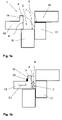
- Figures 1a to 1d show schematically different positions of a compression space 4 of a device 1 according to the invention with a compression space 4 for accommodating the conductors 2, 3 (see Figure 1b ) which can be taken in a connection process.
- Figure 1a a removal position in which the compression space 4 is open
- Figure 1b an insertion position in which there is an insertion opening 9
- Figures 1c and 1d each welding position.
- the compression chamber 4 is defined by an ultrasonically transmitting sonotrode 15, an anvil 16, a lateral delimitation element 17 and a slide element 18.
- the compression space 4 has a right-angled inner edge, which serves as a controlled contact surface when inserting the conductors 2, 3 and determines the shape of the connection point to be created, i.e. the compacting height A and the compacting width B (see Fig Figure 6c ) pretends.
- the compression space 4 is delimited by sections of boundary surfaces 5, 6, 7, 8 adjoining one another.
- the boundary surfaces include a working surface 5 of the ultrasound-transmitting sonotrode 15 and an anvil surface 6 which is arranged opposite the working surface 5 and which is arranged on the anvil 16 .
- the sliding element 18 includes a retaining element 14 which keeps a strand 20 away from the compression space 4 .
- the retaining element 14 is designed here as a protruding element.
- the strand 20 is connected to the conductors 2, 3, which is not explicitly shown in the sectional views 1b to 1d.
- the conductors 2, 3 are compacted by pushing the slide element 28, as shown in FIG figures 1b and 1c is indicated, is shifted towards the lateral delimiting element 17 in the direction S1.
- the compression space 4 is essentially delimited by the sonotrode 15 , the anvil 16 , the delimiting element 17 and the slide element 18 .
- the anvil 16 is first displaced in the direction S2 towards the slide element 18 and then, as in Figure 1d indicated, shifted together with the lateral delimiting element 17 in direction S3 towards the sonotrode 15.
- the strand 20 remains on the side of the retaining element 14 facing away from the slide surface 8 and is thus kept away from the compression space 4 .
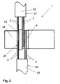
- figure 2 shows a device 1 according to the invention in plan view.
- a first group of conductors 2 of a first cable 32 and a first group of conductors 3 of a second cable 33 are brought up to the compression space 4 from opposite sides.
- a strand 20 runs on the side of the retaining element 14 which faces away from the compression space 4 and is arranged on a slide element 18 .
- the strand 20 is prevented from entering the compression space 4 by the retaining element 14 .
- the conductors 2, 3 can be compacted and welded undisturbed.
- the strand 20 comprises conductors 2', 3' belonging to the two opposite cables 32, 33.
- the conductors 2', 3' of the strand 20 are connected via cable sheaths 37, 38 to the conductors 2, 3 leading into the compression chamber 4.
- the strand 20 may have a previously made weld node.
- a support surface 23 for the at least one strand 20 (not shown explicitly) is arranged in the assembly area 21 adjacent to the retaining element 14 and is designed as a depression.
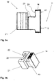
- figure 4 shows another example of a slide element 18 'in a sectional view.
- FIG 5 shows a protective hood 10 in a perspective view.
- the protective hood 10 can be moved over the compression chamber 4, which is not shown in this figure, so that it is covered in the welding position.
- the protective hood 10 is designed in such a way that the conductors 2, 3 and the strand 20, which are also not shown in this figure, can run from an outer area 25 of the protective hood 10 into the compression space 4 when the protective hood 10 covers the compression space 4 in the welding position covers.
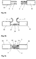
- FIGS 8a to 8c show schematically the method according to the invention.
- a first conductor 2' of the first cable 32 and a first conductor 3' of the second cable 33 are led from opposite sides to a compression chamber 4, which is not explicitly shown.
- a compression chamber 4 which is not explicitly shown.
- the still unconnected ends of the remaining conductors 2, 3 can easily be kept away from the compression space.
- This strand 20 is positioned so that it is kept away from the compression space 4 by the retaining element 14, in which the second conductors 2, 3 of the opposite cables are deposited.
- a second welded connection between the second conductors 2, 3 of the opposite cables 32, 33 can now be produced without any problems.
Description
Die Erfindung betrifft eine Vorrichtung und ein Verfahren zum Ultraschallverbinden von elektrischen Leitern, sowie eine Verwendung eines Schieberelements zum Ultraschallverbinden von Gruppen von Leitern.The invention relates to a device and a method for ultrasonically connecting electrical conductors, and to the use of a slide element for ultrasonically connecting groups of conductors.
Vorrichtungen zum Ultraschallverbinden sind z.B. als mobile Handgeräte sowie als stationäre Geräte bekannt und kommen bevorzugt zum Verschweissen von länglichem Schweissgut wie z.B. elektrischen Leitern wie Litzen zum Einsatz. Ein Leiter kann mehrere Einzeldrähte umfassen.Devices for ultrasonic joining are known, for example, as mobile hand-held devices and as stationary devices and are preferably used for welding elongated weld metal such as electrical conductors such as stranded wires. A conductor can contain several strands.
Die zu verschweissenden Leiter, insbesondere die abisolierten freien Enden der Leiter, werden typischerweise in einen Verdichtungsraum eingebracht, in welchem die Leiter in Kontakt miteinander gebracht werden und mit Ultraschallschwingungen beaufschlagt werden. Der Verdichtungsraum ist in der Regel in lateraler Richtung, d.h. in einer Richtung quer zu einem lichten Durchtrittsbereich für das Schweissgut, zumindest einseitig von einer Arbeitsfläche einer Sonotrode begrenzt. Typischerweise wird die Sonotrode mittels eines Ultraschall-Konverters z.B. zu longitudinalen oder torsionalen Ultraschallschwingungen angeregt. Über die im Allgemeinen profilierte Arbeitsfläche werden die Schwingungen der Sonotrode auf das Schweissgut, zum Beispiel die Leiterenden, übertragen. Der Arbeitsfläche der Sonotrode gegenüberliegend ist in der Regel eine Ambossfläche einer Gegenelektrode oder eines Ambosses angeordnet. Zudem kann der Verdichtungsraum durch Begrenzungsflächen seitlicher Begrenzungselemente und/oder Schieberelemente zusätzlich begrenzt sein, sodass der Verdichtungsraum zumindest beim Verschweissen weitgehend vollständig in lateraler Richtung umschlossen ist. Der Verdichtungsraum kann beispielsweise derart verstellbar ausgebildet sein, dass das Schweissgut durch Verringerung der Querschnittsfläche des lichten Durchtritts während des Schweissens verdichtet werden kann. Dies kann z.B. durch relative Verschiebung des Schieber- und/oder Begrenzungselements und/oder des Ambosses bezüglich der Schweissfläche erreicht werden.The conductors to be welded, in particular the stripped free ends of the conductors, are typically introduced into a compression space in which the conductors are brought into contact with one another and ultrasonic vibrations are applied to them. The compression space is generally delimited in the lateral direction, ie in a direction transverse to a clear passage area for the weld metal, at least on one side by a working surface of a sonotrode. Typically, the sonotrode is excited by means of an ultrasonic converter, for example to produce longitudinal or torsional ultrasonic vibrations. The vibrations of the sonotrode are transmitted to the weld metal, for example the conductor ends, via the generally profiled working surface. An anvil surface of a counter-electrode or an anvil is generally arranged opposite the working surface of the sonotrode. In addition, the compression space can be additionally delimited by boundary surfaces of lateral delimitation elements and/or slide elements, so that the compression space is largely completely enclosed in the lateral direction, at least during welding. The Compression Room can, for example, be adjustable in such a way that the weld metal can be compacted by reducing the cross-sectional area of the clear passage during welding. This can be achieved, for example, by moving the slide and/or limiting element and/or the anvil relative to the welding surface.
Der Amboss, das Begrenzungselement und/oder das Schieberelement können dabei derart beweglich gelagert sein, dass vor oder nach einem Schweissvorgang eine Einlege- bzw. Entnahmeöffnung erzeugt werden kann, an welcher der Verdichtungsraum in lateraler Richtung offen ist. Auf diese Weise kann das Schweissgut in den Verdichtungsraum eingelegt und wieder aus diesem entnommen werden.The anvil, the delimiting element and/or the slide element can be movably mounted in such a way that an insertion or removal opening can be produced before or after a welding process, at which the compression space is open in the lateral direction. In this way, the weld metal can be placed in the compression space and removed from it again.
Sollen Kabel, das heisst gebündelte Leiter, in Längsrichtung miteinander verbunden werden, die nicht nur jeweils freie Enden aufweisen, sondern die bereits miteinander verbunden sind, von denen zum Beispiel ein Teil der Leiter bereits eine Verbindung in Längsrichtung aufweist, so kann sich das Einlegen der Leiter in den Verdichtungsraum schwierig gestalten. Es muss sichergestellt werden, dass die Leiter mit der bereits bestehenden Verbindung nicht in den Verdichtungsraum gelangen.If cables, i.e. bundled conductors, are to be connected to one another in the longitudinal direction, which not only each have free ends, but which are already connected to one another, of which, for example, some of the conductors already have a connection in the longitudinal direction, the insertion of the Make the ladder into the compression space difficult. It must be ensured that the conductors with the existing connection do not enter the compression space.
Diese Schwierigkeit tritt beispielsweise auf, wenn drei Kabel mit je zwei Leitern derart verbunden werden sollen, dass die Leitungen von zwei Kabeln in einem Kabel weitergeführt werden und so zwei parallele Y-Verbindungsstellen oder Y-Knoten erstellt werden sollen. Für jede der zwei Y-Knoten müssen jeweils zwei Leiter von einer Seite und ein Leiter von der gegenüberliegenden Seite in den Verdichtungsraum geführt werden und alle anderen Leiter vom Verdichtungsraum ferngehalten werden.This difficulty occurs, for example, when three cables, each with two conductors, are to be connected in such a way that the lines from two cables are continued in one cable and so two parallel Y-junctions or Y-nodes are to be created. For each of the two Y-nodes, two conductors must be routed into the compression space from one side and one conductor from the opposite side, and all other conductors must be kept away from the compression space.
Diese Schwierigkeit tritt ebenfalls auf, wenn vier Kabel mit je zwei Leitern derart verbunden werden sollen, dass jeweils zwei Kabel von gegenüberliegenden Seiten an den Verdichtungsraum geführt werden und zwei parallele X-Verbindungsstellen oder X-Knoten zu erstellen sind. In jedem der X-Knoten laufen vier Leiter, die jeweils zu einem der Kabel gehören, zusammen. Die Leiter können jeweils Gruppen von Leitungsdrähten umfassen.This difficulty also occurs when four cables, each with two conductors, are to be connected in such a way that two cables are routed from opposite sides to the compression space and two parallel X-connection points or X-nodes are to be created. Four conductors, each belonging to one of the cables, converge in each of the X-nodes. The conductors may each comprise groups of conducting wires.
Derartige Verbindungen werden für geschirmte und/oder mehradrige Hochspannungskabel benötigt, zum Beispiel mit Kupferleitern oder Aluminiumleitern.Such connections are required for shielded and/or multi-core high-voltage cables, for example with copper conductors or aluminum conductors.
Derartige Verbindungen können für verdrillte Leitungen, abgeschirmte Leitungen, abgeschirmte und verdrillte Leitungen, sowie abgeschirmten Kabel gewünscht sein. Häufig ist es notwendig, die Abisolierlänge, die Länge der entfernten Abschirmung und/oder die Entdrilllänge kurz zu halten, um Störungen der elektromagnetischen Verträglichkeit (EVM) zu vermeiden oder verringern.Such connections may be desired for twisted pairs, shielded wires, shielded and twisted pairs, and shielded cables. It is often necessary to keep the stripping length, shield-removed length, and/or untwisting length short to avoid or reduce electromagnetic compatibility (EVM) interference.
Derartige Verbindungen können auch zum Tragen kommen, wenn einer der Leiter kein Leiterdraht ist, sondern ein Kontaktteil, das mit einem gegenüberliegenden Leiter verbunden werden soll.Such connections can also come into play when one of the conductors is not a conductor wire but a contact part which is to be connected to an opposite conductor.
Die bestehenden Verbindungen oder auch nicht zu verschweissende Enden müssen von dem Verdichtungsraum ferngehalten werden. Beim manuellen Einlegen kann dies gewährleistet werden, indem der Bediener die entsprechenden Leiter von dem Verdichtungsraum weghält. Gewöhnlich wird der Verdichtungsraum jedoch während der Verkleinerung des Verdichtungsraums und während der Ultraschallbeaufschlagung zum Schutz des Bedieners von einer Schutzhaube abgedeckt. Die nicht zu verschweissenden Enden und/oder die bestehenden Verbindungen können dann also nicht mehr ohne Weiteres festgehalten werden. Es kann daher nicht zuverlässig sichergestellt werden, dass die zusätzlichen Stränge nicht in den Verdichtungsraum geraten.The existing connections or ends that are not to be welded must be kept away from the compression space. In the case of manual loading, this can be ensured by the operator holding the relevant conductors away from the compression space. Usually, however, the compression space is covered by a protective hood during compression space reduction and ultrasonic impingement to protect the operator. The ends that are not to be welded and/or the existing connections can then no longer be easily held. It can therefore not be reliably ensured that the additional strands do not get into the compression space.
Der Strang wird daher in der Regel in grossem Abstand um den Verdichtungsraum herumgeführt und eine gemeinsame Abschirmung muss auf einer langen Strecke um die Verbindungsstelle entfernt werden und/oder eine Verdrillung muss auf einer langen Strecke um die Verbindungsstelle aufgehoben werden.The string is therefore typically routed a large distance around the compression space and a common shield must be removed a long distance around the joint and/or a twist must be broken a long distance around the joint.
Es ist daher die Aufgabe der Erfindung, die Nachteile des Standes der Technik zu überwinden. Insbesondere ist es eine Aufgabe der Erfindung, eine Vorrichtung, ein Verfahren zum Verschweissen sowie eine Leiteranordnung bereitzustellen, welche bei gleichzeitig komfortabler Handhabung ein einfaches und zuverlässiges Verbinden auch von Kabeln mit mehreren parallel verlaufenden Strängen ermöglichen, ohne dass die Abschirmung und/oder die Verdrillung auf einer grösseren Länge aufgehoben werden muss.It is therefore the object of the invention to overcome the disadvantages of the prior art. In particular, it is an object of the invention to provide a device, a method for welding and a conductor arrangement which, while at the same time being easy to handle, also enable cables with several strands running in parallel to be connected easily and reliably, without the shielding and/or twisting breaking up a greater length must be saved.
Diese Aufgaben werden insbesondere durch die Merkmalskombinationen der unabhängigen Ansprüche gelöst.These objects are achieved in particular by the feature combinations of the independent claims.
Die Aufgabe wird gelöst durch eine Vorrichtung zum Ultraschallverbinden von elektrischen Leitern. Bei der Vorrichtung handelt es sich insbesondere um eine halbautomatische Vorrichtung, bei welcher die Leiter manuell herangeführt und eingelegt werden müssen.The object is achieved by a device for ultrasonically connecting electrical conductors. The device is, in particular, a semi-automatic device in which the conductors have to be fed in and inserted manually.
Die Vorrichtung weist einen Verdichtungsraum zur Aufnahme der Leiter auf. Insbesondere können abisolierte Enden von Leitungsdrähten oder Litzen in den Verdichtungsraum eingebracht werden. Es können auch Leiter mit Zwischenausisolierungen in den Verdichtungsraum gebracht werden.The device has a compression space for accommodating the conductors. In particular, stripped ends of line wires or stranded wires can be introduced into the compression space. Conductors with intermediate insulation can also be brought into the compression space.
Der Verdichtungsraum ist in einer Schweissposition von Abschnitten aneinander angrenzender Begrenzungsflächen begrenzt. Diese Begrenzungsflächen umfassen zumindest eine Arbeitsfläche einer ultraschall-übertragenden Sonotrode und eine der Arbeitsfläche gegenüberliegend angeordneten Ambossfläche, welche an einem Amboss angeordnet ist.In a welding position, the compression space is delimited by sections of boundary surfaces that adjoin one another. These boundary surfaces comprise at least one working surface of an ultrasound-transmitting sonotrode and an anvil surface which is arranged opposite the working surface and which is arranged on an anvil.
Während des Schweissvorgangs werden Ultraschallschwingungen von der Arbeitsfläche auf die Leitungen übertragen.During the welding process, ultrasonic vibrations are transmitted from the work surface to the cables.
Die Vorrichtung weist insbesondere eine Schutzhaube auf, die über den Verdichtungsraum bewegt werden kann, so dass dieser in der Schweissposition abgedeckt ist. Die Schutzhaube ist derart ausgebildet ist, dass die Leiter von einem Aussenbereich der Vorrichtung in den Verdichtungsraum verlaufen können, wenn die Schutzhaube den Verdichtungsraum in der Schweissposition abdeckt.In particular, the device has a protective hood that can be moved over the compression space so that it is covered in the welding position. The protective hood is designed in such a way that the conductors can run from an outer region of the device into the compression space when the protective hood covers the compression space in the welding position.
Die Schutzhaube ist bevorzugt quer zur Durchtrittsrichtung der Leiter über den Verdichtungsraum in eine geschlossene Stellung verschiebbar.The protective hood can preferably be slid into a closed position transversely to the passage direction of the conductors over the compression space.
Die Schutzhaube kann ein Sichtfenster aufweisen, welches in der geschlossenen Stellung oberhalb des Verdichtungsraums angeordnet ist und welches eine visuelle Überprüfung des Schweissvorgangs erlaubt.The protective hood can have a viewing window, which is arranged above the compression space in the closed position and which allows a visual check of the welding process.
Erfindungsgemäss ist mindestens ein Rückhalteelement vorgesehen, zum Fernhalten mindestens eines Stranges vom Verdichtungsraum. Der Strang ist mit zumindest einem Teil der zu verbindenden Leiter verbunden. Bevorzugt handelt es sich um einen Leiterstrang. Die Vorrichtung ist derart ausgebildet, dass das Rückhalteelement den Strang zumindest während des Ultraschallverbindens vom Verdichtungsraum fernhält.According to the invention, at least one retaining element is provided for keeping at least one strand away from the compression space. The strand is connected to at least part of the conductors to be connected. It is preferably a strand of conductors. The device is designed in such a way that the retaining element keeps the strand away from the compression chamber at least during the ultrasonic joining.
Der zurückzuhaltende Leiterstrang und die zu verbindenden Leiter können jeweils zu gemeinsamen Kabeln gehören. Der zurückzuhaltende Strang kann insbesondere eine zuvor hergestellte Schweissverbindung umfassen oder auch freie Enden, die nicht zu verschweissen sind. Der Strang kann auch ein Kontaktteil oder mehrere Kontaktteile umfassen, die bereits mit einem oder mehreren Leitern eines Kabels verbunden sind.The strand of conductors to be retained and the conductors to be connected may each belong to common cables. The strand to be held back can, in particular, comprise a previously produced welded connection or also free ends which are not to be welded. The string may also include a contact portion or multiple contact portions already provided with one or more Conductors of a cable are connected.
Bei dem Rückhalteelement kann es sich um ein aktives oder passives Element handeln. Es kann sich beispielsweise um ein Klemmelement, eine Klammer oder einen Haken handeln, mit welchen der Strang von dem Verdichtungsraum weggezogen wird. Es kann sich auch um ein Stosselement handeln, welches den Strang von dem Verdichtungsraum wegdrückt.The restraining element can be an active or passive element. For example, it can be a clamping element, a clamp or a hook, with which the strand is pulled away from the compression space. It can also be a push element that pushes the strand away from the compression space.
Ein aktives Rückhaltelement kann ein bewegliches Fixierelement umfassen. Soll der Strang in einer bestimmten Parkposition gehalten werden, so kann das Fixierelement aktiviert werden. Das Fixierelement kann als Klammer, Klemme oder Riegel ausgeführt sein.An active restraint element may include a moveable fixation element. If the strand is to be held in a specific parking position, the fixing element can be activated. The fixing element can be designed as a bracket, clamp or bolt.
Die Aktivierung kann mechanisch geschehen, zum Beispiel durch das Verschieben oder Umlegen des Fixierelements. Alternativ kann das Rückhaltelement beispielsweise elektrisch oder elektronisch von einer Rückhaltesteuerung aktivierbar sein. Zusätzlich kann die Rückhaltesteuerung zum Erzeugen eines Signals ausgelegt sein, das an eine Steuerung des Ultraschallerzeugers weiterleitbar ist, so dass der Schweissprozess nicht beginnt, bevor das Rückhaltelement aktiviert ist.Activation can take place mechanically, for example by moving or turning over the fixing element. Alternatively, the restraining element can be activated, for example, electrically or electronically by a restraint control. In addition, the restraint control can be designed to generate a signal that can be forwarded to a controller of the ultrasonic generator, so that the welding process does not begin before the restraint element is activated.
Für ein Entnehmen des Stranges ist das Rückhaltelement insbesondere wieder deaktivierbar.The retaining element can in particular be deactivated again in order to remove the strand.
Bevorzugt weist die Vorrichtung eine Schutzhaube auf, die derart ausgebildet ist, dass der zurückzuhaltende Strang von einem Aussenbereich der Vorrichtung in die Vorrichtung verläuft, wenn die Schutzhaube den Verdichtungsraum in der Schweissposition abdeckt.The device preferably has a protective hood which is designed in such a way that the strand to be retained runs from an outer area of the device into the device when the protective hood covers the compression space in the welding position.
Der zurückzuhaltende Strang kann insbesondere von einer Seite der Vorrichtung auf die andere Seite der Vorrichtung führen und während des Schweissens, wenn die Schutzhaube den Verdichtungsraum in der Schweissposition abdeckt, von der einen Seite der Schutzhaube durch die Schutzhaube auf die andere Seite der Schutzhaube führen.In particular, the strand to be restrained can lead from one side of the device to the other side of the device and, during welding, when the protective hood covers the compression space in the welding position, from one side of the protective hood through the protective hood to the other side of the protective hood.
Die Vorrichtung bietet mit dem Rückhalteelement und insbesondere mit der Schutzhaube eine Parkposition für Stränge, zum Beispiel für bestehende Verbindungen oder auch nicht zu verschweissende Enden, in der die Stränge eine definierte Position einnehmen und von dem Verdichtungsraum ferngehalten werden.With the retaining element and in particular with the protective hood, the device offers a parking position for strands, for example for existing connections or ends that are not to be welded, in which the strands assume a defined position and are kept away from the compression space.
Die Schutzhaube erlaubt eine Aufnahme des Strangs. Der Strang muss also während des Schweissens nicht an der Schutzhaube vorbei geführt werden. Die Vorrichtung ermöglicht daher eine Positionierung des zurückzuhaltenden Strangs in der Nähe des Verdichtungsraums.The protective hood allows the strand to be accommodated. The strand therefore does not have to be guided past the protective hood during welding. The device therefore enables the string to be retained to be positioned close to the compression space.
Es können somit freie Enden von Kabeln verbunden werden, die bereits verbundene Enden parallel verlaufender Leiter aufweisen, da diese Leiter zuverlässig in einer Parkposition gehalten werden können.It is thus possible to connect free ends of cables which already have connected ends of parallel conductors, since these conductors can be reliably held in a parking position.
Der Verdichtungsraum weist einen lichten Durchtritt auf, durch welchen die Leiter z.B. in den Verdichtungsraum hineinragen oder durch den Verdichtungsraum hindurchragen können. Der lichte Durchtritt ist in der Regel zumindest in der Schweissposition in lateraler Richtung, d.h. im Wesentlichen quer zur Durchtrittsrichtung, von den Begrenzungsflächen begrenzt und weitgehend vollständig umschlossen.The compression space has a clear passage through which the conductors can protrude, for example, into the compression space or through the compression space. The clear passage is generally delimited by the boundary surfaces and largely completely enclosed at least in the welding position in the lateral direction, ie essentially transversely to the direction of passage.
Bevorzugt sind die Begrenzungsflächen in eine Anordnung bringbar, in welcher eine Einlegeöffnung gebildet ist. Die Einlegeöffnung der Einlegeposition versteht sich als laterale Zugangsöffnung zum Verdichtungsraum, durch welche die Leiter in der typischerweise weitgehend quer zur Durchtrittsrichtung gerichteten Einlegerichtung in den Verdichtungsraum eingelegt werden können.The boundary surfaces can preferably be brought into an arrangement in which an insertion opening is formed. The insertion opening of the insertion position is understood as a lateral access opening to the compression space, through which the conductors can be inserted into the compression space in the insertion direction, which is typically directed largely transversely to the direction of passage.
In der Regel wird die Einlegeöffnung durch Änderung der Anordnung wenigstens einer der Begrenzungsflächen, insbesondere der Ambossfläche, geschaffen.As a rule, the insertion opening is created by changing the arrangement of at least one of the boundary surfaces, in particular the anvil surface.
In der Schweissposition kann während des Schweissvorgangs der lichte Durchtritt des Verdichtungsraums im Querschnitt verringert werden.In the welding position, the clear passage of the compression space can be reduced in cross section during the welding process.
In der Regel sind die Begrenzungsflächen weitgehend eben, wobei z.B. Profilierungen oder andere Strukturierungen der Flächen vorhanden sein können. Grundsätzlich ist es je nach Erfordernis allerdings auch denkbar, dass die Begrenzungsflächen z.B. gekrümmt sein können.As a rule, the boundary surfaces are largely flat, with e.g. profiling or other structuring of the surfaces being possible. In principle, however, it is also conceivable, depending on the requirement, for the boundary surfaces to be curved, for example.
In einer vorteilhaften Ausführung der Vorrichtung umfassen die Begrenzungsflächen eine Schieberfläche, welche an einem Schieberelement angeordnet ist, und insbesondere eine der Schieberfläche gegenüberliegend angeordnete Seitenfläche, welche an einem seitlichen Begrenzungselement angeordnet ist.In an advantageous embodiment of the device, the boundary surfaces include a slide surface which is arranged on a slide element, and in particular a side surface which is arranged opposite the slide surface and which is arranged on a lateral boundary element.
Die Schieberfläche und die Seitenfläche können aufeinander zu bewegbar sein, um die Querschnittsfläche des Verdichtungsraums vor dem oder während des Schweissens zu verkleinern.The slide surface and the side surface can be moved towards one another in order to reduce the cross-sectional area of the compression space before or during welding.
Die Seitenfläche und/oder die Schieberfläche können weitgehend senkrecht zur Arbeitsfläche angeordnet sein.The side surface and/or the slide surface can be arranged largely perpendicularly to the work surface.
Das Rückhalteelement ist insbesondere an dem Schieberelement angeordnet.The retaining element is arranged in particular on the slide element.
Das Schieberelement kann zum Beispiel eine von der Schieberfläche wegweisenden Rückhaltefläche aufweisen, die zum Beispiel an einem auf dem Schieberelement vorstehenden Element angeordnet ist, welches als Rückhalteelement wirkt. Das vorstehende Element kann einen Aufnahmeraum für den wegzuhaltenden Strang definieren und den Strang von dem Verdichtungsraum wegdrücken.The slide element can, for example, have a retaining surface pointing away from the slide surface, which is arranged, for example, on an element protruding on the slide element, which acts as a retaining element. The protruding element can define a receiving space for the string to be kept away and push the string away from the compression space.
In einer vorteilhaften Ausführung umfasst die Vorrichtung ein Schieberelement mit Schieberfläche und Rückhaltelement. Das Rückhalteelement weist eine von dem Verdichtungsraum wegweisende Rückhaltefläche auf, die parallel zur Schieberfläche angeordnet ist, und bevorzugt nah an der Schieberfläche angeordnet ist. Das Rückhalteelement ist fest mit dem Schieberelement verbunden und kann mit dem Schieberelement mitbewegt werden. Der zurückzuhaltende Strang kann daher einen geringen Abstand zu dem Verdichtungsraum einnehmen. Es ist daher möglich, auch einen Strang zu positionieren, der durch kurze aus einem Kabel vorstehende Leiterenden gebildet wird.In an advantageous embodiment, the device comprises a slide element with a slide surface and a retaining element. The retaining element has a retaining surface facing away from the compression chamber, which is arranged parallel to the slide surface and is preferably arranged close to the slide surface. The retaining element is firmly connected to the slide element and can be moved with the slide element. The strand to be retained can therefore be at a small distance from the compression space. It is therefore possible to also position a strand that is formed by short conductor ends protruding from a cable.
Insbesondere weist das Schieberelement eine Auflagefläche für den abzulegenden Strang auf, die derartig ausgebildet ist, dass ein abgelegter Strang dort verbleibt, bis er wieder entnommen wird, auch wenn das Schieberelement bewegt wird. Es kann das Rückhalteelement entsprechend ausgebildet sein, zum Beispiel als aktives Element, welches den Strang fixiert. Alternativ oder zusätzlich kann die Auflagefläche als Vertiefung in dem Schieberelement ausgebildet sein, in welcher der Strang aufgenommen wird.In particular, the slide element has a support surface for the strand to be deposited, which is designed in such a way that a deposited strand remains there until it is removed again, even if the slide element is moved. The retaining element can be designed accordingly, for example as an active element which fixes the strand. Alternatively or additionally, the bearing surface can be designed as a depression in the slide element, in which the strand is received.
In einer vorteilhaften Ausbildung umfasst die Vorrichtung ein Schieberelement mit Schieberfläche, wobei das Schieberelement einen von der Schieberfläche wegweisenden Montagebereich aufweist. Der Montagebereich kann Verbindungsmittel umfassen, die zur Befestigung des Schieberelements an einer maschinenseitigen Aufnahme dienen, über welche das Schieberelement in eine Bewegung versetzt werden kann.In an advantageous embodiment, the device comprises a slide element with a slide surface, the slide element having a mounting area pointing away from the slide surface. The assembly area can include connecting means, which are used to fasten the slide element to a receptacle on the machine, via which the slide element can be set in motion.
Typischerweise erstreckt sich das Rückhalteelement, zum Beispiel ein vorstehendes Element, in eine Richtung, die senkrecht zu der Richtung steht, in welche die Schieberfläche weist.Typically, the retaining element, for example a protruding element, extends in a direction perpendicular to the direction in which the pusher surface faces.
Das Rückhalteelement kann unmittelbar an den Montagebereich anschliessen, so dass der wegzuhaltende Strang auf dem Montagebereich abgelegt werden kann.The retaining element can directly adjoin the assembly area, so that the strand to be kept away can be placed on the assembly area.
Bevorzugt umfasst das Schieberelement eine Auflagefläche für den mindestens einen wegzuhaltenden Strang, die als Absenkung im Montagebereich ausgebildet ist. Der wegzuhaltende Strang kann dann in der Regel näher an den Abschnitt der Schieberfläche herangebracht werden, welcher eine Begrenzungsfläche des Verdichtungsraums bildet. Der Abstand zwischen Verdichtungsraum und Auflagefläche ist also geringer als bei einer nicht abgesenkten Auflagefläche.The slide element preferably includes a support surface for the at least one strand to be kept away, which is designed as a depression in the assembly area. The strand to be kept away can then generally be brought closer to that section of the slide surface which forms a boundary surface of the compression space. The distance between the compression chamber and the bearing surface is therefore smaller than in the case of a bearing surface that is not lowered.
In einer vorteilhaften Ausbildung umfasst die Vorrichtung ein Schieberelement mit Schieberfläche, wobei das Schieberelement eine Ausnehmung aufweist, in welcher ein Einsatz platziert werden kann.In an advantageous embodiment, the device comprises a slide element with a slide surface, the slide element having a recess in which an insert can be placed.
Das Rückhaltelement kann an dem Schieber ausgebildet sein oder an einem Einsatz, der in der Ausnehmung platzierbar ist.The retaining element can be formed on the slide or on an insert that can be placed in the recess.
In die Ausnehmung kann zum Beispiel ein Einsatz eingelegt werden, der eine Auflagefläche für einen Strang bietet.For example, an insert can be inserted into the recess, which offers a bearing surface for a strand.
Der Einsatz kann beispielweise eine Nut aufweisen.The insert can have a groove, for example.
Die Nut kann so tief sein, dass ein Strang in der Nut zurückgehalten wird. Auf dem Einsatz oder dem Schieber kann alternativ oder zusätzlich ein vorstehenden Element angebracht sie, das als Barriere zum Verdichtungsraum wirkt.The groove can be so deep that a strand is retained in the groove. Alternatively or additionally, a protruding element can be attached to the insert or the slide, which acts as a barrier to the compression space.
Der Einsatz kann auch eine Ausnehmung aufweisen, deren Kontur mit der Aussenkontur eines Kontaktteils korrespondiert, so dass das Kontaktteil in den Einsatz einlegbar ist.The insert can also have a recess whose contour corresponds to the outer contour of a contact part, so that the contact part can be inserted into the insert.
Der Einsatz kann auswechselbar sein. Es kann ein Einsatz mit einer Nut eingelegt werden, deren Querschnittsfläche und/oder Durchmesser an die Querschnittsfläche und/oder den Durchmesser des zu verarbeitenden Strangs angepasst ist.The insert can be exchangeable. An insert with a groove can be inserted, the cross-sectional area and/or diameter of which is adapted to the cross-sectional area and/or the diameter of the strand to be processed.
Es können Befestigungsmittel zum Befestigen des Einsatzes in der Ausnehmung des Schieberelements vorgesehen sein, zum Beispiel für eine Schraubverbindung. Es kann auch ein Formschluss zwischen Einsatz und Ausnehmung herstellbar sein, wenn zum Beispiel die Ausnehmung als Schiebekulisse für eine am Einsatz ausgebildete komplementäre Struktur ausbildet ist.Fastening means can be provided for fastening the insert in the recess of the slide element, for example for a screw connection. It can also be possible to create a positive fit between the insert and the recess if, for example, the recess is designed as a sliding link for a complementary structure formed on the insert.
In einer vorteilhaften Ausführung der Vorrichtung umfasst die Schutzhaube mindestens einen ersten Durchlass zum Durchführen der zu verbindenden Leiter und insbesondere mindestens eine erste Anlegekante zum Ausrichten der Leiter.In an advantageous embodiment of the device, the protective hood comprises at least one first opening for passing through the conductors to be connected and in particular at least one first contact edge for aligning the conductors.
Der Durchlass kann in Form einer Öffnung, einer Ausnehmung, einer Klappe oder eines elastischen Elements vorliegen und ermöglicht das Heranführen der Leiter von einem Aussenbereich der Schutzhaube in den Verdichtungsraum, wenn dieser von der Schutzhaube abgedeckt ist.The passage can be in the form of an opening, a recess, a flap or an elastic element and allows leading the conductors from an outer area of the protective hood into the compression space when this is covered by the protective hood.
Die Anlegekante kann in dem Durchlass angeordnet sein. Die Schutzhaube deckt den Verdichtungsraum ab, damit ein Bediener nicht in die Nähe des Verdichtungsraums kommt. Ein Bediener kann daher auch die Leiter nicht mehr in der Nähe des Verdichtungsraums festhalten. Die Anlegekante kann die Leiter in Richtung eines Anschlags drücken und damit eine Halte- und/oder Ausrichtfunktion übernehmen, die gewährleistet, dass die Leiter nicht verrutschen, wenn die Vorrichtung in der Schweissposition ist.The landing edge can be arranged in the passage. The protective hood covers the compression space to prevent an operator from getting close to the compression space. An operator can therefore no longer hold the ladder in the vicinity of the compression space. The contact edge can press the ladder in the direction of a stop and thus assume a holding and/or alignment function which ensures that the ladder does not slip when the device is in the welding position.
Zusätzlich weist die Schutzhaube mindestens eine weitere Anlegekante zum Ausrichten des mindestens einen zurückzuhaltenden Stranges auf. Für den Strang gilt ebenfalls, dass er nicht mehr von einem Bediener festgehalten werden kann, wenn die Schutzhaube schliesst, also den Verdichtungsraum abdeckt. Die weitere Anlegekante kann den Strang in Richtung eines Anschlags drücken und damit den Strang halten und/oder ausrichten.In addition, the protective hood has at least one further contact edge for aligning the at least one strand to be held back. It also applies to the train that it can no longer be held by an operator when the protective hood closes, i.e. covers the compression space. The further contact edge can press the strand in the direction of a stop and thus hold and/or align the strand.
Die weitere Anlegekante kann in demselben Durchlass angeordnet sein, wie eine erste Anlegekante, oder es kann ein weiterer Durchlass vorgesehen ist, durch welchen der Strang führbar ist.The further feed edge can be arranged in the same passage as a first feed edge, or a further passage can be provided through which the strand can be guided.
Bevorzugt weist die Schutzhaube beidseitig einen Durchlass für Leiter auf, so dass Leiter von gegenüberliegenden Seiten in den Verdichtungsraum verlaufen können, und beidseitig erste und zweite Anlegekanten.The protective hood preferably has an opening for conductors on both sides, so that conductors can run into the compression chamber from opposite sides, and first and second contact edges on both sides.
In einer vorteilhaften Weiterbildung der Vorrichtung sind die Anlegekanten Teile einer Haltevorrichtung, mit welcher die Leiter und/oder der Strang ausserhalb des Verdichtungsraums, insbesondere während eines Schweissvorgangs festlegbar sind und, insbesondere nach einem Schweissvorgang wieder freigebbar sind.In an advantageous development of the device, the contact edges are parts of a holding device with which the conductor and/or the strand outside the compression space, in particular can be fixed during a welding process and, in particular, can be released again after a welding process.
Die Schutzhaube kann jeweils elastische Klemmlippen aufweisen, deren freie Enden die Anlegekanten bilden. Mittels der Klemmlippen können die Leiter und der Strang bei geschlossener Schutzhaube an einer Anschlagfläche festgeklemmt werden. Auf diese Weise ist eine Lage der Leiter und des Stranges ausserhalb des Verdichtungsraums weitgehend festgelegt.The protective hood can each have elastic clamping lips, the free ends of which form the contact edges. With the protective cover closed, the conductor and the strand can be clamped to a stop surface by means of the clamping lips. In this way, a position of the conductor and the strand outside of the compression space is largely fixed.
Vorteilhafterweise umfasst die Vorrichtung ein auswechselbares Schieberelement mit Rückhalteelement und die Vorrichtung umfasst insbesondere mindestens ein weiteres Schieberelement ohne Rückhalteelement. Das Schieberelement kann dann demontiert werden und durch ein anderes Schieberelement ersetzt werden. Auf diese Weise ist die Vorrichtung umrüstbar und kann für unterschiedliche elektrische Kabel oder Leiter verwendet werden, insbesondere für Kabel mit und ohne zurückzuhaltenden Strang oder für Kabel mit unterschiedlich dicken Strängen oder unterschiedlich vielen Leitern.Advantageously, the device includes an exchangeable slide element with a retaining element, and the device includes, in particular, at least one further slide element without a retaining element. The slide element can then be dismantled and replaced with another slide element. In this way, the device can be converted and used for different electrical cables or conductors, in particular for cables with and without strands to be retained or for cables with strands of different thicknesses or different numbers of conductors.
Die Vorrichtung kann auch ein Schieberelement mit auswechselbarem Einsatz aufweisen. Zum Beispiel kann ein Einsatz mit einer Nut demontiert werden und durch einen anderen Einsatz ohne Nut oder mit einer Nut, die eine andere Querschnittsfläche und/oder einen anderen Durchmesser aufweist, ersetzt werden.The device can also have a slide element with an exchangeable insert. For example, an insert with a groove can be disassembled and replaced with another insert without a groove or with a groove having a different cross-sectional area and/or diameter.
Die Aufgabe wird weiter gelöst durch eine Anlage zum Ultraschallverbinden mit mindestens zwei Vorrichtungen zum Ultraschallverbinden von elektrischen Leitern, wovon mindestens eine Vorrichtung zum Ultraschallverbinden eine Vorrichtung ist, wie sie oben beschrieben ist. Die Anlage ist insbesondere so ausgebildet, dass zwei oder mehr Sonotroden und korrespondierende Ambosse parallel zueinander angeordnete Verdichtungsräume begrenzen.The object is further achieved by a system for ultrasonic bonding with at least two devices for ultrasonic bonding of electrical conductors, of which at least one device for ultrasonic bonding is a device as described above. In particular, the system is designed in such a way that two or more sonotrodes and corresponding anvils limit compression chambers arranged parallel to one another.
Es können dann gleichzeitig zwei oder mehr ausisolierte Bereiche von denselben Leitern in die jeweilige Verdichtungsräume eingebracht werden und mit Leiterenden, Kontaktelementen oder zwischenausisolierten Bereichen weiterer Leiter verbunden werden, während ein Strang aus mindestens einem Verdichtungsraum ferngehalten wird.Two or more stripped areas of the same conductors can then be introduced into the respective compression chambers at the same time and connected to conductor ends, contact elements or intermediate stripped areas of other conductors, while one strand is kept away from at least one compression chamber.
Die Aufgabe wird ausserdem gelöst durch ein Verfahren zum Ultraschallverbinden von elektrischen Leitern in einem Verdichtungsraum einer Vorrichtung zum Ultraschallverbinden, insbesondere wie oben beschrieben.The object is also achieved by a method for ultrasonically connecting electrical conductors in a compression space of a device for ultrasonically connecting, in particular as described above.
Der Verdichtungsraum ist in einer Schweissposition zumindest von Abschnitten von Begrenzungsflächen begrenzt. Die Begrenzungsflächen umfassen eine Arbeitsfläche einer ultraschallübertragenden Sonotrode und eine Ambossfläche, welche an einem Amboss angeordnet ist.In a welding position, the compression space is limited at least by sections of boundary surfaces. The confining surfaces include a working surface of an ultrasonically transmitting sonotrode and an anvil surface, which is arranged on an anvil.
Ein Rückhalteelement ist an der Vorrichtung vorgesehen zum Fernhalten mindestens eines Stranges aus dem Verdichtungsraum, der mit zumindest einem Teil der zu verbindenden Leiter verbunden ist. Insbesondere dient das Rückhaltelement zum Fernhalten eines Leiterstranges.A retaining element is provided on the device for keeping out of the compression space at least one strand which is connected to at least part of the conductors to be connected. In particular, the retaining element is used to keep a strand of conductors away.
Zunächst erfolgt das Erstellen einer Einlegeposition des Verdichtungsraums, in welcher der Verdichtungsraum zum Einlegen der Leiter an einer Einlegeöffnung zumindest teilweise offen ist.First, an insertion position of the compression space is created, in which the compression space is at least partially open for insertion of the conductor at an insertion opening.
Die zu verbindenden Leiter werden dann in den Verdichtungsraum eingelegt. Vorher, gleichzeitig oder nachher erfolgt ein Positionieren des mindestens einen Stranges an dem Rückhalteelement. Insbesondere wird der Strang auf einer von einer Schieberfläche wegweisenden Seite eines an einem Schiebelement vorstehenden Elements positioniert. Der Strang kann an einer von der Schieberfläche wegweisenden Rückhaltefläche anliegen.The conductors to be connected are then placed in the compression space. Positioning takes place before, at the same time or afterwards the at least one strand on the retaining element. In particular, the strand is positioned on a side of an element protruding on a sliding element, which side faces away from a sliding surface. The strand may abut a retaining surface facing away from the pusher surface.
Es wird dann eine Schweissposition des Verdichtungsraums erstellt und der Strang wird durch das Rückhalteelement von dem Verdichtungsraum in der Schweissposition ferngehalten.A welding position of the compression space is then created and the strand is kept away from the compression space in the welding position by the retaining element.
Es kann dann der Schweissvorgang durch Beaufschlagen mit Ultraschallwellen erfolgen.The welding process can then take place by applying ultrasonic waves.
Das Rückhalteelement hindert den Strang während des Einlegevorgangs und während des Schweissens daran, in den Verdichtungsraum zu gelangen.The retaining element prevents the strand from entering the compression space during the insertion process and during the welding.
Zum Beispiel kann ein vorstehendes Element an dem Schieberelement eine Barriere bilden zwischen einem Auflagebereich und dem Verdichtungsraum.For example, a protruding element on the slide element can form a barrier between a bearing area and the compression space.
In einer vorteilhaften Ausbildung des Verfahrens wird das Rückhalteelement aus der Einlegeposition in eine Schweissposition bewegt und dabei bleibt die relative Anordnung von den Leitern und dem mindestens einen Strang erhalten. Zum Beispiel kann ein Schieberelement mit Schieberfläche und einem vorstehenden Element in Richtung einer gegenüberliegenden Begrenzungsfläche geschoben werden. Die zu verbindenden Leiter sind zwischen der Schieberfläche und der gegenüberliegenden Begrenzungsfläche angeordnet und der wegzuhaltende Strang liegt auf der von der Schieberfläche wegweisenden Seite des vorstehenden Elements, bevorzugt an einer von der Schieberfläche wegweisenden Rückhaltefläche.In an advantageous embodiment of the method, the retaining element is moved from the insertion position into a welding position, and the relative arrangement of the conductors and the at least one strand is retained. For example, a slider element with a slider surface and a protruding element can be pushed towards an opposite boundary surface. The conductors to be connected are arranged between the slide surface and the opposite boundary surface and the strand to be held away lies on the side of the protruding element facing away from the slide surface, preferably on a retaining surface facing away from the slide surface.
Wird der Schieber bewegt, werden die Leiter im Verdichtungsraum zusammengeschoben und gleichzeitig hat der Strang die Möglichkeit, der Bewegung zu folgen, so dass keine unnötige Spannung auf dem Strang und/oder einem Kabel, zum dem die Leiter und der Strang gehören, liegt.When the slide is moved, the conductors are pushed together in the compression space and at the same time the string has the opportunity to follow the movement, so that there is no unnecessary tension on the string and/or a cable to which the conductors and string belong.
In einer bevorzugten Weiterbildung des Verfahrens wird eine Schutzhaube über den Verdichtungsraum bewegt, so dass dieser in der Schweissposition abgedeckt ist. Die Leiter verlaufen von einem Aussenbereich in den Verdichtungsraum, und der Strang verläuft von einem Aussenbereich der Schutzhaube in die Schutzhaube hinein, und bevorzugt auf der gegenüberliegenden Seite wieder hinaus.In a preferred development of the method, a protective hood is moved over the compression space so that it is covered in the welding position. The conductors run from an outer area into the compression space, and the cord runs from an outer area of the protective hood into the protective hood and preferably out again on the opposite side.
Die Leiter können dabei durch mindestens einen ersten Durchlass in der Schutzhaube an den Verdichtungsraum herangeführt werden, und die Leiter können mit mindestens einer Anlegekante ausgerichtet werden.The conductors can be brought to the compression space through at least one first opening in the protective hood, and the conductors can be aligned with at least one contact edge.
Der mindestens eine Strang kann durch mindestens eine weitere Anlegekante ausgerichtet werden, die bevorzugt in mindestens einem weiteren Durchlass der Schutzhaube angeordnet ist.The at least one strand can be aligned by at least one additional contact edge, which is preferably arranged in at least one additional passage of the protective hood.
In einer Variante des Verfahrens werden Leiter von zwei gegenüberliegenden Seiten in den Verdichtungsraum geführt und in Längsrichtung miteinander verbunden. Alternativ oder zusätzlich können Leiter von derselben Seite in den Verdichtungsraum geführt und verbunden werden.In a variant of the method, conductors are fed into the compression space from two opposite sides and connected to one another in the longitudinal direction. Alternatively or additionally, conductors can be fed into the compression space from the same side and connected.
Der wegzuhaltende Strang kann mindestens einen länglichen Leiter umfassen, der während des Verbindens der zu verbindenden Leiter an dem Verdichtungsraum vorbeigeführt ist.The strand to be held off may comprise at least one elongate conductor which is routed past the compression space during the connection of the conductors to be connected.
Der wegzuhaltende Strang kann zu zwei oder mehr von gegenüberliegenden Seiten an den Verdichtungsraum geführten Kabeln gehören, die ausserdem Leiter umfassen, welche verbunden werden sollen.The string to be kept away may belong to two or more cables routed from opposite sides to the compression space, which also include conductors to be connected.
Der wegzuhaltende Leiterstrang kann zum Beispiel durch jeweils gemeinsame Abschirmungen, Isolierungen und/oder Kabelumhüllungen mit den zu verbindenden Leitern verbunden sein.The strand of conductors to be kept away can be connected to the conductors to be connected, for example, by common shielding, insulation and/or cable sheathing.
In einer bevorzugten Ausführung des Verfahrens wird eine erste Gruppe von Leitern mindestens zweier Kabel, die von gegenüberliegenden Seiten an den Verdichtungsraum herangeführt sind, in den Verdichtungsraum eingelegt.In a preferred embodiment of the method, a first group of conductors of at least two cables, which are routed to the compression space from opposite sides, are laid in the compression space.
Insbesondere kann mindestens eine zweite Gruppe von Leitern so positioniert werden, dass sie durch das Rückhalteelement von dem Verdichtungsraum ferngehalten werden.In particular, at least a second group of conductors can be positioned such that they are kept away from the compression space by the retaining element.
Eine erste Schweissverbindung der ersten Gruppe von Leitern wird hergestellt und bildet einen Leiterstrang.A first welded connection of the first group of conductors is produced and forms a conductor strand.
Anschliessend werden die mit der ersten Schweissverbindung verbundenen Leiter so positioniert, dass sie durch das Rückhalteelement von dem Verdichtungsraum ferngehalten werden, und die zweite Gruppe von Leitern wird in den Verdichtungsraum abgelegt. Eine zweite Schweissverbindung der zweiten Gruppe von Leitern wird hergestellt, die parallel zu der ersten Schweissverbindung angeordnet ist.Subsequently, the conductors connected to the first weld joint are positioned such that they are kept away from the compression space by the retaining element, and the second group of conductors is deposited in the compression space. A second weld joint of the second group of conductors is made, which is arranged parallel to the first weld joint.
In einer vorteilhaften Ausbildung des Verfahrens kann zunächst zwischen Leitern zweier Kabel, die von einer ersten Seite an den Verdichtungsraum herangeführt werden und Leitern eines dritten Kabels, das von der anderen Seite an den Verdichtungsraum herangeführt ist, ein erster Y-Knoten hergestellt werden. Der erste Y-Knoten kann dann so positioniert werden, dass er durch das Rückhalteelement von dem Verdichtungsraum ferngehalten wird und weitere Leiter der drei Kabel können in den Verdichtungsraum eingelegt werden, so dass ein weiterer Y-Knoten hergestellt werden kann. Die hergestellten Y-Knoten sind parallel zueinander angeordnet.In an advantageous embodiment of the method, initially between conductors of two cables that are brought up to the compression space from a first side and conductors of a third Cable, which is brought from the other side to the compression space, a first Y-node can be made. The first Y-node can then be positioned so that it is kept clear of the compression space by the restraining member and further conductors of the three cables can be laid into the compression space so that another Y-node can be made. The Y-nodes produced are arranged parallel to each other.
In einer weiteren vorteilhaften Ausbildung des Verfahrens kann zunächst zwischen Leitern zweier Kabel, die von einer ersten Seite an den Verdichtungsraum herangeführt werden und Leitern zweier weiterer Kabel, die von der anderen Seite an den Verdichtungsraum herangeführt werden, ein erster X-Knoten hergestellt werden. Der erste X-Knoten kann dann so positioniert werden, dass er durch das Rückhalteelement von dem Verdichtungsraum ferngehalten wird und weitere Leiter der vier Kabel können in den Verdichtungsraum eingelegt werden, so dass ein weiterer X-Knoten hergestellt werden kann. Die hergestellten X-Knoten sind parallel zueinander angeordnet.In a further advantageous embodiment of the method, a first X-node can first be created between conductors of two cables that are routed to the compression space from a first side and conductors of two other cables that are routed to the compression space from the other side. The first X-node can then be positioned so that it is kept clear of the compression space by the restraining member and further conductors of the four cables can be inserted into the compression space so that another X-node can be made. The produced X-nodes are arranged parallel to each other.
In einer weiteren vorteilhaften Ausbildung des Verfahrens können wie oben beschrieben parallel angeordnete X-Knoten oder Y-Knoten von Kabeln mit verdrillten Leitern hergestellt werden. Das Rückhalteelement sorgt dafür, dass der bereits erstellte Knoten ohne Risiko nah an den Verdichtungsraum gebracht werden kann. Die Verdrillung der Leiter muss um die Verbindungsstelle herum also nur auf einer kurzen Strecke aufgehoben werden.In a further advantageous embodiment of the method, X-nodes or Y-nodes arranged in parallel can be produced from cables with twisted conductors, as described above. The retaining element ensures that the knot that has already been created can be brought close to the compression space without any risk. The conductors only have to be twisted around the connection point for a short distance.
Derartig verbundene Kabel können für CAN Busse in Fahrzeugen verwendet werden, wo die Anforderung besteht, dass die Verdrillung auf einer Länge von zum Beispiel maximal 15-30mm aufgehoben sein darf.Cables connected in this way can be used for CAN buses in vehicles, where there is a requirement that the twisting may be untwisted over a length of, for example, a maximum of 15-30mm.
Während des Schweissvorgangs kann eine Schutzhaube in eine geschlossene Position bewegt werden, in welcher sie den Verdichtungsraum abdeckt.During the welding process, a protective hood can be moved to a closed position, in which it covers the compression space.
Grundsätzlich ist es möglich, das Verfahren auf alle Sorten von mehradrigen Kabeln anzuwenden, insbesondere auf solche, bei denen eine kurze Abisolierlänge des Kabels gewünscht ist.In principle, it is possible to apply the process to all types of multi-core cables, especially to those where a short stripping length of the cable is desired.
Die Aufgabe wird ausserdem gelöst durch eine Verwendung eines Schieberelements, das mindestens ein vorstehendes Element aufweist, zum Fernhalten eines Strangs von einem Verdichtungsraum, in welchem parallel zum Strang verlaufende Leiter verbunden werden soll. Die Verwendung erfolgt in einer Vorrichtung zum Ultraschallverbinden von elektrischen Leitern, insbesondere wie oben beschrieben.The object is also achieved by using a slide element, which has at least one projecting element, for keeping a strand away from a compression space in which conductors running parallel to the strand are to be connected. It is used in a device for ultrasonically connecting electrical conductors, in particular as described above.
Der ferngehaltene Strang kann eine bereits zuvor hergestellte Verbindungsstelle umfassen.The strand held off may include a previously made joint.
Insbesondere können daher Gruppen von Leitern verbunden werden, die im verbunden Zustand parallel zueinander angeordnete Verbindungsstellen aufweisen.In particular, therefore, groups of conductors can be connected which, in the connected state, have connection points arranged parallel to one another.
Die Leiter können vor dem Verbinden ein abisoliertes Ende aufweisen.The conductors may have a stripped end prior to connection.
Ein zu verbindender Leiter kann auch eine Zwischenausisolierung aufweisen, die im Verdichtungsraum platziert wird, so dass derselbe Leiter in den Verdichtungsraum hinein und aus dem Verdichtungsraum heraus verläuft.A conductor to be connected may also have an intermediate lining placed in the compression space so that the same conductor runs in and out of the compression space.
Eine weitere Ausführung bezieht sich auf ein Verfahren zum Umrüsten einer Vorrichtung zum Ultraschallverbinden von Schweissgut, wie zum Beispiel elektrischen Leitern, mit einem Verdichtungsraum zur Aufnahme des Schweissgutes. Der Verdichtungsraum ist in einer Schweissposition von Abschnitten aneinander angrenzender Begrenzungsflächen begrenzt. Die Begrenzungsflächen umfassen eine Arbeitsfläche einer ultraschallübertragenden Sonotrode, eine Ambossfläche, welche an einem Amboss angeordnet ist und eine Schieberfläche, welche an einem Schieberelement angeordnet ist. Das Schieberelement wird ersetzt durch ein Schieberelement, welches mindestens Rückhalteelement, bevorzugt ein vorstehendes Element, aufweist zum Fernhalten mindestens eines Strangs aus dem Verdichtungsraum.A further embodiment relates to a method for retrofitting a device for ultrasonically connecting weld metal, such as electrical conductors, with a compression space for receiving the weld metal. In a welding position, the compression space is delimited by sections of boundary surfaces that adjoin one another. The boundary surfaces include a working surface of an ultrasonically transmitting sonotrode, an anvil surface which is arranged on an anvil and a slide surface which is arranged on a slide element. The slide element is replaced by a slide element which has at least a retaining element, preferably a protruding element, for keeping at least one strand out of the compression space.
Nicht gemäß der Erfindung ist Leiterstruktur mit mindestens einem ersten und einem zweiten Leiterstrang, die jeweils Leiter aufweisen offenbart.Not according to the invention, a conductor structure with at least one first and one second strand of conductors, each of which has conductors, is disclosed.
Die Leiterstränge umfassen Verbindungsstellen, an denen Leiter in Längsrichtung miteinander durch Ultraschallverbinden verbunden sind, insbesondere in einem Verfahren wie oben beschrieben, so dass die Verbindungsstellen parallel zueinander angeordnet sind. Bei den Verbindungsstellen kann es sich um X-Knoten oder Y-Knoten handeln.The conductor strands comprise joints at which longitudinal conductors are joined together by ultrasonic joining, in particular in a method as described above, so that the joints are arranged parallel to each other. The junctions can be X-nodes or Y-nodes.
Zu verschiedenen Leitersträngen gehörige Leiter sind ausserhalb der Verbindungsstelle über eine Länge zusammengefasst, insbesondere durch eine Verdrillung, eine Abschirmung oder eine Isolationshülle, und die Leiter sind um die parallelen Verbindungsstellen auf einer freigestellten Länge nicht zusammengefasst. Insbesondere ist die freigestellte Länge
- für Leiter mit einem Durchmesser von kleiner gleich 1mm oder einem Nennquerschnitt kleiner gleich als 0.5mm2 kleiner als der 40fache Durchmesser des Leiters,
- für Leiter mit einem Durchmesser von grösser 1mm und kleiner gleich 5mm oder einem Nennquerschnitt grösser 0.5 mm2 und kleiner gleich 10mm2 kleiner als der 20fache Durchmesser des Leiters und
- für Leiter mit einem Durchmesser von grösser 5mm oder einem Nennquerschnitt grösser 10mm2 kleiner als der 10fache Durchmesser des Leiters.
- for conductors with a diameter of less than or equal to 1mm or a nominal cross section of less than or equal to 0.5mm 2 less than 40 times the diameter of the conductor,
- for conductors with a diameter greater than 1mm and less than or equal to 5mm or a nominal cross-section greater than 0.5 mm 2 and less than or equal to 10mm 2 less than 20 times the diameter of the conductor and
- for conductors with a diameter greater than 5mm or a nominal cross-section greater than 10mm 2 less than 10 times the diameter of the conductor.
Der Nennquerschnitt ist als elektrisch wirksamer Querschnitt definiert. Die Ermittlung des Nennquerschnitts erfolgt durch die Messung des elektrischen Widerstands bei einer Umgebungstemperatur von 20°C. Der Nennquerschnitt wird als Grössenangabe häufig bei feindrahtigen Leitern, Starkstromkabel und -leitungen verwendet. Der Nennquerschnitt ist in seinen Abmessungen kleiner als der geometrische Querschnitt.The nominal cross section is defined as the electrically effective cross section. The nominal cross-section is determined by measuring the electrical resistance at an ambient temperature of 20°C. The nominal cross-section is often used as a size specification for fine-wire conductors, power cables and lines. The dimensions of the nominal cross-section are smaller than the geometric cross-section.
Die Leiter sind insbesondere ausserhalb der Verbindungsstelle verdrillt und um die parallelen Verbindungsstellen auf einer Länge von maximal 30mm, bevorzugt maximal 15mm, entdrillt.In particular, the conductors are twisted outside the connection point and untwisted around the parallel connection points over a maximum length of 30 mm, preferably a maximum of 15 mm.
Die verdrillten Leiter weisen bevorzugt einen Nennquerschnitt von 0.8mm2 bis 4mm2 auf.The twisted conductors preferably have a nominal cross section of 0.8mm 2 to 4mm 2 .
Alternativ oder zusätzlich verlaufen die Leiter ausserhalb der Verbindungsstelle als Kabel in Kabelabschirmungen und/oder Isolationshüllen und auf einer Länge von maximal 70mm, bevorzugt 60mm, um die Verbindungsstellen liegt keine Kabelabschirmung und/oder Isolationshülle vor.Alternatively or additionally, the conductors run outside the connection point as cables in cable shields and/or insulation sleeves and over a maximum length of 70 mm, preferably 60 mm; there is no cable shielding and/or insulation sleeve around the connection points.
Die Leiter der abgeschirmten Kabel weisen bevorzugt einen Querschnitt von 4mm2-8mm2 auf.The conductors of the shielded cables preferably have a cross-section of 4mm 2 -8mm 2 .
Die Erfindung wird im Folgenden anhand von Abbildungen exemplarischer Ausführungsbeispiele näher erläutert.The invention is explained in more detail below with reference to illustrations of exemplary embodiments.
Es zeigen schematisch
- Figur 1a
- einen Verdichtungsraum einer erfindungsgemässen Vorrichtung in einer Entnahmeposition;
- Figur 1b
- den Verdichtungsraum der erfindungsgemässen Vorrichtung in einer Einlegeposition;
- Figur 1c
- den Verdichtungsraum der erfindungsgemässen Vorrichtung in einer ersten Schweissposition;
- Figur 1d
- den Verdichtungsraum der erfindungsgemässen Vorrichtung in einer zweiten Schweissposition;
Figur 2- eine erfindungsgemässe Vorrichtung in Draufsicht;
- Figur 3a
- ein Schieberelement in Schnittdarstellung;
- Figur 3b
- das Schieberelement perspektivischer Darstellung;
Figur 4- ein Schieberelement in Schnittdarstellung;
Figur 5- eine Schutzhaube in perspektivischer Darstellung;
- Figur 6a
- einen doppelten Y-Knoten in einer ersten Seitenansicht;
- Figur 6b
- den doppelten Y-Knoten in einer zweiten Seitenansicht;
- Figur 6c
- den doppelten Y-Knoten in einer Schnittansicht entlang der Schnittlinie A-A aus
Figur 6b ; Figur 7- einen doppelten X-Knoten in einer Seitenansicht;
- Figuren 8a-8c
- die Schritte eines erfindungsgemässen Verfahrens.
- Figure 1a
- a compression chamber of a device according to the invention in a removal position;
- Figure 1b
- the compression chamber of the device according to the invention in an insertion position;
- Figure 1c
- the compression space of the device according to the invention in a first welding position;
- Figure 1d
- the compression space of the device according to the invention in a second welding position;
- figure 2
- a device according to the invention in plan view;
- Figure 3a
- a slide element in section;
- Figure 3b
- the slider element perspective view;
- figure 4
- a slide element in section;
- figure 5
- a protective hood in a perspective view;
- Figure 6a
- a double Y-node in a first side view;
- Figure 6b
- the double Y-node in a second side view;
- Figure 6c
- Figure out the double Y node in a section view along section line AA
Figure 6b ; - figure 7
- a double X-node in a side view;
- Figures 8a-8c
- the steps of a method according to the invention.
Herbei zeigen
Der Verdichtungsraum 4 wird von einer ultraschallübertragenden Sonotrode 15, einem Amboss 16, einem seitlichen Begrenzungselement 17 und einem Schieberelement 18 definiert.The
Der Verdichtungsraum 4 weist eine rechtwinklige Innenkante auf, welche als kontrollierte Anlagefläche beim Einlegen der Leiter 2, 3 dient und formgebend für die zu erstellende Verbindungsstelle ist, also die Kompaktierhöhe A und die Kompaktierbreite B (siehe
In der Schweissposition ist der Verdichtungsraum 4 von Abschnitten aneinander angrenzender Begrenzungsflächen 5, 6, 7, 8 begrenzt. Die Begrenzungsflächen umfassen eine Arbeitsfläche 5 der ultraschallübertragenden Sonotrode 15 und eine der Arbeitsfläche 5 gegenüberliegend angeordnete Ambossfläche 6, welche an dem Amboss 16 angeordnet ist.In the welding position, the
In den Verdichtungsraum 4 werden von gegenüberliegenden Seiten des Verdichtungsraums 4 Leiter 2, 3 eingeführt.In the
Das Schiebeelement 18 umfasst ein Rückhalteelement 14, das einen Strang 20 von dem Verdichtungsraum 4 fernhält. Das Rückhalteelement 14 ist hier als vorstehendes Element ausgebildet.The sliding
Der Strang 20 ist mit den Leitern 2, 3 verbunden, was in den Schnittdarstellungen 1b bis 1d nicht explizit dargestellt ist.The
Während des Ultraschallverbindungsprozesses werden die Leiter 2, 3 kompaktiert, indem das Schieberelement 28, wie in
In der Schweissposition ist der Verdichtungsraum 4 im Wesentlichen von der Sonotrode 15, dem Amboss 16, dem Begrenzungselement 17 und dem Schieberelement 18 begrenzt. Dazu wird, wie in
Während des gesamten Prozesses bleibt der Strang 20 auf der von der Schieberfläche 8 abgewandten Seite des Rückhalteelements 14 liegen und wird so aus dem Verdichtungsraum 4 ferngehalten.During the entire process, the
Der Strang 20 umfasst insbesondere Leiter 2', 3', die zu den beiden gegenüberliegenden Kabeln 32, 33 gehören. Die Leiter 2', 3' des Strangs 20 sind über Kabelumhüllungen 37, 38 mit den in den Verdichtungsraum 4 führenden Leitern 2, 3 verbunden. Der Strang 20 kann einen vorher hergestellten Schweissknoten aufweisen.In particular, the
An dem Schieberelement 18' ist ein Rückhalteelement 14, das als vorstehendes Element ausgebildet ist, angeordnet. Das Rückhalteelement 14 weist eine zu dem Verdichtungsraum 4 weisende Fläche 27 auf, die parallel zur Schieberfläche 8 angeordnet ist, in diesem Fall einen Teil der Schieberfläche 8 bildet. Das Rückhalteelement 14 weist überdies eine von dem Verdichtungsraum 4 wegweisende Fläche 24 auf, welche einen in der Figur nicht explizit gezeigten wegzuhaltenden Strang von dem Verdichtungsraum 4 wegdrücken kann.A retaining
Das Schieberelement 18' besitzt einen von der Schieberfläche 8 wegweisenden Montagebereich 21.The slide element 18' has a mounting
In dem Montagebereich 21 ist benachbart zum Rückhalteelement 14 eine Auflagefläche 23 für den mindestens einen nicht explizit dargestellten Strang 20 angeordnet, die als Absenkung ausgebildet ist.A
Im Montagebereich 21 ist ausserdem eine Montageöffnung 26 mit einer Montagefläche 22 vorgesehen, mit welcher eine Verbindung zu einem nicht dargestellten maschinenseitigen Gegenstück hergestellt werden kann. Die Verbindung ist leicht mit einem Werkzeug lösbar, so dass das Schieberelement 18' auswechselbar ist.In the
In dem Schieberelement 18' ist eine Ausnehmung 40 vorgesehen, in die ein Einsatz 41 einlegbar ist. In dem Einsatz 41 ist eine Nut 42 angebracht, die eine Auflagefläche 23 für einen Strang bietet. In die Ausnehmung kann zum Beispiel für andere Anwendungszwecke ein anderer Einsatz 41' eingelegt werden, der eine Nut 42' mit grösserer Querschnittsfläche aufweist.A
Die Schutzhaube 10 umfasst einen ersten Durchlass 11 zum Durchführen der Leiter 2, 3 und eine erste Anlegekante 13 zum Ausrichten der Leiter 2, 3, sowie eine zweite Anlegekante 19 zum Ausrichten des mindestens einen Stranges 20. Ein zweiter Durchlass 12 ist vorgesehen, durch welchen der Strang 20 verlaufen kann.The
Der erste und der zweite Durchlass 11, 12 sowie die erste und zweite Anlegekante 13, 19 sind jeweils beidseitig angebracht, so dass Leiter und Strang beidseitig in die Schutzhaube, bzw. aus der Schutzhaube verlaufen können.The first and the
Die Anlegekanten 13, 19 sind Teile einer Haltevorrichtung 28, hier elastische Klemmlippen 29, 30, mit welcher die Leiter 2, 3 und der Strang 20 ausserhalb des Verdichtungsraums 4, insbesondere während eines Schweissvorgangs festlegbar sind und, insbesondere nach einem Schweissvorgang, wieder freigebbar sind.
Bei einem Y-Knoten werden zwei Leiter 2 mit einem Leiter 3 in Längsrichtung verbunden.In a Y-node, two
Die erfindungsgemässe Vorrichtung und das erfindungsgemässe Verfahren finden vor allem dann Anwendung, wenn wie im Beispiel gezeigt, zwei Kabel 32 je zwei Leiter 2, 2' heranführen, die jeweils mit einem von zwei Leitern 3, 3' zu verbinden sind, welche von einem Kabeln 33 von der gegenüberliegenden herangeführt werden.The device according to the invention and the method according to the invention are used above all when, as shown in the example, two
Es werden in zwei Schritten zwei parallel zueinander angeordnete Y-Knoten 29 hergestellt. In einem ersten Schritt wird ein erster Y-Knoten 29 erstellt. In einem zweiten Schritt wird dieser von dem Rückhaltelement in einer Parkposition gehalten und die übrigen Leiter werden zu einem zweiten Y-Knoten verbunden.Two Y-
Die Enden der Leiter 2, 2', 3, 3' können dabei kurz ausgebildet sein, so dass die aus dem Kabelmantel 30 herausgeführte Länge E der Leiter 2, 2', 3, 3' 40mm und die Gesamtlänge F der Verbindung 70mm betragen kann. Eine Länge C von 15mm der Leiter 2, 2', 3, 3' ist abisoliert, um eine Kompaktierlänge D von 11-13mm zu erreichen. Die Kompaktierbreite B kann dabei etwa 5mm betragen und die Kompaktierhöhe A der Y-Verbindung 29 3.6 - 4.3mm.The ends of the
Bei einem X-Knoten werden jeweils zwei Leiter 2 die von einer ersten Seite an die Verbindungsstelle 34 herangeführt werden, mit zwei Leitern 3, die von der gegenüberliegenden Seite an die Verbindungsstelle 34 herangeführt werden, in Längsrichtung verbunden.In the case of an X node, two
Die erfindungsgemässe Vorrichtung und das erfindungsgemässe Verfahren finden vor allem dann Anwendung, wenn wie im Beispiel gezeigt, zwei Kabel 32 je zwei Leiter 2, 2' heranführen, die mit je zwei Leitern 3, 3' verbunden werden, welche von zwei Kabeln 33 von der gegenüberliegende Seite herangeführt werden.The device according to the invention and the method according to the invention are mainly used when, as shown in the example, two
Es werden dann in zwei Schritten zwei parallel zu einander angeordnete X-Knoten 34 hergestellt. In einem ersten Schritt wird ein erster X-Knoten 34 erstellt. In einem zweiten Schritt wird dieser von dem Rückhaltelement in einer Parkposition gehalten und die übrigen Leiter werden zu einem zweiten X-Knoten 34 verbunden.Two X-nodes 34 arranged parallel to one another are then produced in two steps. In a first step, a
Die Abisolierlänge G kann 40mm betragen und die Gesamtlänge F der X-Verbindung 70mm, bei einer Kompaktierlänge D von 15mm.The stripping length G can be 40mm and the total length F of the X-connection 70mm, with a compacting length D of 15mm.
Nach Erstellen der X-Verbindung kann die X-Verbindungstelle 34 mit einer Isolierung und mit Gehäuseteilen umgeben werden.After creating the X-connection, the
Gemäss
Gemäss
In einem weiteren Schritt, der in
Dieser Strang 20 wird so positioniert, dass er durch das Rückhalteelement 14 von dem Verdichtungsraum 4 ferngehalten wird, in den die zweiten Leiter 2, 3 der gegenüberliegenden Kabel abgelegt werden.This
Es kann nun problemlos eine zweite Schweissverbindung zwischen den zweiten Leitern 2, 3 der gegenüberliegenden Kabel 32, 33 hergestellt werden.A second welded connection between the
Claims (17)
- Device (1) for ultrasonically connecting electrical conductors (2, 2', 3, 3'), for forming a conductor structure with at least a first and a second conductor strand,with a compression space (4) for receiving the conductors (2, 3), the compression space (4) being delimited in a welding position by sections of mutually adjoining boundary surfaces (5, 6, 7, 8), which boundary surfaces comprise a working surface (5) of an ultrasound-transmitting sonotrode (15) and an anvil surface (6) arranged opposite the working surface (5),characterised in thatat least one retaining element (14) is provided for keeping at least one conductor strand (20) which is connected to at least part of the conductors (2, 2', 3, 3') away from the compression space (4), the device (1) being designed in such a manner that the retaining element (14) keeps the conductor strand (20) away from the compression space (4) at least during the ultrasonically connecting, wherein the boundary surfaces comprise a gather surface (8) arranged on a gather element (18, 18') and the retaining element (14) is arranged on the gather element (18, 18').
- Device according to claim 1, wherein the retaining element (14) is formed as a protruding element on the gather element (18, 18').
- Device according to claim 1 or 2, wherein the gather element (18, 18') has a mounting region (21) pointing away from the gather surface (8), and the gather element (18, 18') preferably comprises in the mounting region (21) a support surface (23) for the at least one conductor strand (20), which support surface is formed in particular as a countersink in the mounting region (21).
- Device according to any one of the preceding claims, wherein the gather element (18, 18') has a recess (40) and the device comprises an insert (41, 41') for insertion into the recess (40), on which an abutment surface (23) for the at least one conductor strand (20) is formed.
- Apparatus according to any one of the preceding claims,
wherein the apparatus comprises a protective hood (10) which is movable over the compression space (4) so that it is covered in the welding position, wherein the protective hood (10) is designed in such a way that the conductors (2, 2', 3, 3') run from an outer region (25) of the apparatus (1) into the compression space (4), when the protective hood (10) covers the compression space (4) in the welding position, and the protective hood (10) being designed in such a way that the conductor strand (20) runs from an outer region (25) of the apparatus (1) into the apparatus (1) when the protective hood (10) covers the compression space (4) in the welding position. - Device according to claim 5, wherein the protective hood (10) comprises at least one first passage (11) for passing through the conductors (2, 2', 3, 3') and in particular at least one first contact edge (13) for aligning the conductors (2, 2', 3, 3'), as well as at least one further contact edge (19) for aligning the at least one conductor strand (20), and wherein preferably a further passage (12) is provided through which the conductor strand (20) can be guided.
- Device according to claim 6, wherein the contact edge (19) for aligning the at least one conductor strand (20) and at least one contact edge (13) for aligning the conductors (2, 2', 3, 3') are parts of a holding device with which the conductors (2, 3) and the conductor strand (20) can be fixed outside the compression space (4), in particular during a welding operation, and can be released again, in particular after a welding operation.
- Device according to one of the preceding claims, wherein the device (1) comprises a replaceable gather element (18, 18') with a retaining element (14) and the device (1) comprises in particular at least one further gather element without a retaining element (14).
- Method for ultrasonic bonding of electrical conductors (2, 3), for forming a conductor structure with at least a first and a second conductor strand, in a compression space (4) of an apparatus (1) for ultrasonic bonding according to one of claims 1 to 8,wherein the compression space (4) is bounded in a welding position at least by sections of boundary surfaces (5, 6, 7, 8), which boundary surfaces (5, 6, 7, 8) comprise a working surface (5) of an ultrasound-transmitting sonotrode (15) and an anvil surface (6), wherein a retaining element (14) is provided for keeping at least one conductor strand (20), which is connected to at least part of the conductors (2, 3), away from the compression space (4),the method comprising the steps of:a.) Providing an insertion position of the compression space (4) in which the compression space (4) is at least partially open for inserting the conductors (2, 3) at an insertion opening (9),b.) Inserting the conductors (2, 3) into the compression chamber (4), and characterised by the following stepsc.) Positioning the at least one conductor strand (20) on the retaining element (14), in particular positioning the conductor strand on a side of an element (14) projecting on a gather element (18, 18') facing away from a gather surface (8),d.) Poviding a welding position of the compression space (4) and keeping the conductor strand (20) away from the compression space (4) in the welding position,e.) Apply ultrasonic vibrations to the conductors (2, 3).
- The method according to claim 8, wherein the retaining element (14) is moved from the insertion position to a welding position while maintaining the relative arrangement of the conductors (2, 3) and the at least one conductor strand (20) .
- Method according to claim 9 or 10, wherein a protective hood (10) is moved over the compression space (4) so that it is covered in the welding position, wherein the conductors (2, 2', 3, 3') pass from an outer region into the compression space (4), and the conductor strand (20) passes from an outer region (25) of the protective bonnet (10) into the protective bonnet (10), and preferably out again.
- Method according to claim 11, wherein the conductors (2, 3, 2', 3') extend through at least one first passage (11) in the protective hood (10) to the compression space (4), and the conductors (2, 3, 2', 3') are aligned in particular with at least one contact edge (13), and wherein the at least one conductor strand (20) is aligned by at least one further contact edge (19), which is preferably arranged in at least one further passage (12) of the protective bonnet (10) .
- Method according to any one of claims 9 to 12, wherein conductors (2, 3, 2', 3') are guided into the compression space (4) from two opposite sides, and the conductors (2, 3, 2', 3') are connected to each other in the longitudinal direction.
- A method according to any one of claims 9 to 13, wherein the conductor string (20) comprises at least one elongate conductor which is guided past the compression space (4) during connection.
- Method according to any one of claims 9 to 14, wherein a first group of conductors (2', 3') of at least two cables (32, 33), which are led to the compression space (4) from opposite sides, is inserted into the compression space (4), in particular at least a second group of conductors (2, 3) is positioned in such a way that they are kept away from the compression space (4) by the retaining element (14), a first welded joint of the first group of conductors (2', 3') is made, then the conductors (2', 3') connected via the first welded joint are positioned in such a way that they are kept away from the compression space (4) by the retaining element (14), the second group of conductors (2, 3) is deposited in the compression space (4) and a second welded joint of the second group of conductors (2, 3) is made.
- A method according to any one of claims 9 to 15,
whereinin a first step a first Y-node (29) is produced between conductors (2') of two cables (32) approaching the compression space (4) from a first side and conductors (3') of a third cable (33) approaching the compression space (4) from the other side, , in a second step the first Y-node (29) is positioned so that it is kept away from the compression space (4) by the retaining element (14), further conductors (2, 3) of the three cables (32, 33) are inserted into the compression space (4) and a further Y-node (29) is produced or whereinin a first step, a first X-node (34) is produced between conductors (2') of two cables (32) approaching the compression space (4) from a first side and conductors (3') of two further cables (33) approaching the compression space (4) from the other side, and, in a second step, the first X-node (34) is positioned in such a way that it is kept away from the compression space (4) by the retaining element (14), further conductors (2, 3) of the four cables (32, 33) are inserted into the compression space (4) and a further X-node (34) is produced. - Use of a retaining element (14) arranged on a gather element (18, 18') for keeping a conductor string (20) away from a compression space (4) for receiving electrical conductors (2, 3) in an apparatus for ultrasonically connecting the electrical conductors (2, 3) according to any one of claims 1-8.
Applications Claiming Priority (1)
| Application Number | Priority Date | Filing Date | Title |
|---|---|---|---|
| PCT/EP2017/076351 WO2019076433A1 (en) | 2017-10-16 | 2017-10-16 | Device and method for ultrasound connection of electrical conductors |
Publications (2)
| Publication Number | Publication Date |
|---|---|
| EP3698441A1 EP3698441A1 (en) | 2020-08-26 |
| EP3698441B1 true EP3698441B1 (en) | 2022-08-10 |
Family
ID=60117682
Family Applications (1)
| Application Number | Title | Priority Date | Filing Date |
|---|---|---|---|
| EP17784638.3A Active EP3698441B1 (en) | 2017-10-16 | 2017-10-16 | Device and method for ultrasound connection of electrical conductors |
Country Status (3)
| Country | Link |
|---|---|
| EP (1) | EP3698441B1 (en) |
| DE (1) | DE112017007765A5 (en) |
| WO (1) | WO2019076433A1 (en) |
Families Citing this family (2)
| Publication number | Priority date | Publication date | Assignee | Title |
|---|---|---|---|---|
| JP7434546B2 (en) * | 2019-11-05 | 2024-02-20 | シュンク ソノジステム ゲゼルシャフト ミット ベシュレンクテル ハフツング | Ultrasonic welding equipment equipped with position detection of mating parts |
| DE102020113672B4 (en) * | 2020-05-20 | 2022-03-03 | Lisa Dräxlmaier GmbH | METHOD AND DEVICE FOR WELDING AT LEAST THREE CABLES, EACH WITH TWO WIRE PROJECTING FROM THE SHEATH OF THE CABLES |
Citations (1)
| Publication number | Priority date | Publication date | Assignee | Title |
|---|---|---|---|---|
| DE102015117020A1 (en) * | 2015-10-06 | 2017-04-06 | Kromberg & Schubert Gmbh | welding connector |
Family Cites Families (3)
| Publication number | Priority date | Publication date | Assignee | Title |
|---|---|---|---|---|
| DE102011014801B4 (en) * | 2011-03-23 | 2019-08-08 | Audi Ag | Method for welding conductors |
| EP2786835A1 (en) * | 2013-04-02 | 2014-10-08 | Telsonic Holding AG | Device for and method of welding by means of ultrasound with a movable limiting surface |
| DE102013209314B3 (en) * | 2013-05-21 | 2014-06-26 | Lisa Dräxlmaier GmbH | Method for electrically connecting wire of electrical conductor with contact elements, involves welding lower portion of individual wires to second contact surface of contact element which is opposite to first contact surface |
-
2017
- 2017-10-16 EP EP17784638.3A patent/EP3698441B1/en active Active
- 2017-10-16 WO PCT/EP2017/076351 patent/WO2019076433A1/en unknown
- 2017-10-16 DE DE112017007765.6T patent/DE112017007765A5/en active Pending
Patent Citations (1)
| Publication number | Priority date | Publication date | Assignee | Title |
|---|---|---|---|---|
| DE102015117020A1 (en) * | 2015-10-06 | 2017-04-06 | Kromberg & Schubert Gmbh | welding connector |
Also Published As
| Publication number | Publication date |
|---|---|
| WO2019076433A1 (en) | 2019-04-25 |
| EP3698441A1 (en) | 2020-08-26 |
| DE112017007765A5 (en) | 2020-04-23 |
Similar Documents
| Publication | Publication Date | Title |
|---|---|---|
| EP1960151B1 (en) | Method for production of a welded connection between electrical conductors by means of an ultrasound welding method | |
| EP1771274B1 (en) | Method for producing a welded joint between electrical wires with a support | |
| DE102013101876B3 (en) | Method for integrally joining a cable with a connection element and configured cable | |
| EP3069419B1 (en) | Device for welding electric conductors | |
| EP2609655B1 (en) | Method and device for connecting an electrical conductor to an electrical contact part | |
| DE10218400B4 (en) | Shielding arrangement on a shield flat cable and method for its production | |
| EP0143936A1 (en) | Device for joining or compressing electric conductors | |
| EP2605881A2 (en) | Method and arrangement for welding electrical conductors | |
| EP3698441B1 (en) | Device and method for ultrasound connection of electrical conductors | |
| DE19909322A1 (en) | Connection structure for jacketed cables | |
| DE10361474B4 (en) | Waterproof seal assembly on a jacketed cable | |
| DE1615659B2 (en) | METHOD AND DEVICE FOR ELECTRICALLY CONNECTING INDIVIDUAL LEADWIRE OF A GROUP OF LEADWIRES | |
| DE19909335A1 (en) | Ultrasonic welding of covered wires for e.g. to connect a shield wire with a ground wire | |
| EP3676043A1 (en) | Method for welding electrical conductors by means of ultrasound and ultrasonic metal welding device | |
| EP3469666B1 (en) | Device and method for crimping of fastener elements | |
| DE102012007846A1 (en) | Crimping apparatus for connecting electrical conductor with electrical contact e.g. cable lug in motor vehicle, has laser welding device that is provided with machining optical system for directing laser beam on contact portion | |
| DE19527123A1 (en) | Method for the electrical connection of two electrical components to one another | |
| EP3631912B1 (en) | Contacting-making method for enamel-insulated conductors | |
| EP0474113B1 (en) | Connection device for multiwire cables | |
| EP3474391B1 (en) | Method for joining at least two multi-strand leads by means of ultrasound | |
| DE102016121909B4 (en) | Sealing of line connectors | |
| DE102016223475B4 (en) | Connection arrangement and method for producing a connection arrangement for stranded conductors in a guide | |
| DE102015117020B4 (en) | Method for producing a line seal of a line harness and method for producing a sealed line connection | |
| DE4435090C1 (en) | Stranded electrical wires with finished ends mfg. jig for use in assembly of equipment and machines | |
| EP3906133B1 (en) | Ultrasonic welding device with position detection of joint partners |
Legal Events
| Date | Code | Title | Description |
|---|---|---|---|
| STAA | Information on the status of an ep patent application or granted ep patent |
Free format text: STATUS: UNKNOWN |
|
| STAA | Information on the status of an ep patent application or granted ep patent |
Free format text: STATUS: THE INTERNATIONAL PUBLICATION HAS BEEN MADE |
|
| PUAI | Public reference made under article 153(3) epc to a published international application that has entered the european phase |
Free format text: ORIGINAL CODE: 0009012 |
|
| STAA | Information on the status of an ep patent application or granted ep patent |
Free format text: STATUS: REQUEST FOR EXAMINATION WAS MADE |
|
| 17P | Request for examination filed |
Effective date: 20200514 |
|
| AK | Designated contracting states |
Kind code of ref document: A1 Designated state(s): AL AT BE BG CH CY CZ DE DK EE ES FI FR GB GR HR HU IE IS IT LI LT LU LV MC MK MT NL NO PL PT RO RS SE SI SK SM TR |
|
| AX | Request for extension of the european patent |
Extension state: BA ME |
|
| DAV | Request for validation of the european patent (deleted) | ||
| DAX | Request for extension of the european patent (deleted) | ||
| STAA | Information on the status of an ep patent application or granted ep patent |
Free format text: STATUS: EXAMINATION IS IN PROGRESS |
|
| STAA | Information on the status of an ep patent application or granted ep patent |
Free format text: STATUS: EXAMINATION IS IN PROGRESS |
|
| 17Q | First examination report despatched |
Effective date: 20210622 |
|
| GRAP | Despatch of communication of intention to grant a patent |
Free format text: ORIGINAL CODE: EPIDOSNIGR1 |
|
| STAA | Information on the status of an ep patent application or granted ep patent |
Free format text: STATUS: GRANT OF PATENT IS INTENDED |
|
| GRAS | Grant fee paid |
Free format text: ORIGINAL CODE: EPIDOSNIGR3 |
|
| GRAA | (expected) grant |
Free format text: ORIGINAL CODE: 0009210 |
|
| STAA | Information on the status of an ep patent application or granted ep patent |
Free format text: STATUS: THE PATENT HAS BEEN GRANTED |
|
| INTG | Intention to grant announced |
Effective date: 20220628 |
|
| AK | Designated contracting states |
Kind code of ref document: B1 Designated state(s): AL AT BE BG CH CY CZ DE DK EE ES FI FR GB GR HR HU IE IS IT LI LT LU LV MC MK MT NL NO PL PT RO RS SE SI SK SM TR |
|
| REG | Reference to a national code |
Ref country code: AT Ref legal event code: REF Ref document number: 1511251 Country of ref document: AT Kind code of ref document: T Effective date: 20220815 Ref country code: CH Ref legal event code: EP |
|
| REG | Reference to a national code |
Ref country code: IE Ref legal event code: FG4D Free format text: LANGUAGE OF EP DOCUMENT: GERMAN |
|
| REG | Reference to a national code |
Ref country code: DE Ref legal event code: R096 Ref document number: 502017013607 Country of ref document: DE |
|
| REG | Reference to a national code |
Ref country code: NL Ref legal event code: MP Effective date: 20220810 |
|
| REG | Reference to a national code |
Ref country code: LT Ref legal event code: MG9D |
|
| PG25 | Lapsed in a contracting state [announced via postgrant information from national office to epo] |
Ref country code: SE Free format text: LAPSE BECAUSE OF FAILURE TO SUBMIT A TRANSLATION OF THE DESCRIPTION OR TO PAY THE FEE WITHIN THE PRESCRIBED TIME-LIMIT Effective date: 20220810 Ref country code: RS Free format text: LAPSE BECAUSE OF FAILURE TO SUBMIT A TRANSLATION OF THE DESCRIPTION OR TO PAY THE FEE WITHIN THE PRESCRIBED TIME-LIMIT Effective date: 20220810 Ref country code: PT Free format text: LAPSE BECAUSE OF FAILURE TO SUBMIT A TRANSLATION OF THE DESCRIPTION OR TO PAY THE FEE WITHIN THE PRESCRIBED TIME-LIMIT Effective date: 20221212 Ref country code: NO Free format text: LAPSE BECAUSE OF FAILURE TO SUBMIT A TRANSLATION OF THE DESCRIPTION OR TO PAY THE FEE WITHIN THE PRESCRIBED TIME-LIMIT Effective date: 20221110 Ref country code: NL Free format text: LAPSE BECAUSE OF FAILURE TO SUBMIT A TRANSLATION OF THE DESCRIPTION OR TO PAY THE FEE WITHIN THE PRESCRIBED TIME-LIMIT Effective date: 20220810 Ref country code: LV Free format text: LAPSE BECAUSE OF FAILURE TO SUBMIT A TRANSLATION OF THE DESCRIPTION OR TO PAY THE FEE WITHIN THE PRESCRIBED TIME-LIMIT Effective date: 20220810 Ref country code: LT Free format text: LAPSE BECAUSE OF FAILURE TO SUBMIT A TRANSLATION OF THE DESCRIPTION OR TO PAY THE FEE WITHIN THE PRESCRIBED TIME-LIMIT Effective date: 20220810 Ref country code: FI Free format text: LAPSE BECAUSE OF FAILURE TO SUBMIT A TRANSLATION OF THE DESCRIPTION OR TO PAY THE FEE WITHIN THE PRESCRIBED TIME-LIMIT Effective date: 20220810 |
|
| PG25 | Lapsed in a contracting state [announced via postgrant information from national office to epo] |
Ref country code: PL Free format text: LAPSE BECAUSE OF FAILURE TO SUBMIT A TRANSLATION OF THE DESCRIPTION OR TO PAY THE FEE WITHIN THE PRESCRIBED TIME-LIMIT Effective date: 20220810 Ref country code: IS Free format text: LAPSE BECAUSE OF FAILURE TO SUBMIT A TRANSLATION OF THE DESCRIPTION OR TO PAY THE FEE WITHIN THE PRESCRIBED TIME-LIMIT Effective date: 20221210 Ref country code: HR Free format text: LAPSE BECAUSE OF FAILURE TO SUBMIT A TRANSLATION OF THE DESCRIPTION OR TO PAY THE FEE WITHIN THE PRESCRIBED TIME-LIMIT Effective date: 20220810 Ref country code: GR Free format text: LAPSE BECAUSE OF FAILURE TO SUBMIT A TRANSLATION OF THE DESCRIPTION OR TO PAY THE FEE WITHIN THE PRESCRIBED TIME-LIMIT Effective date: 20221111 |
|
| PG25 | Lapsed in a contracting state [announced via postgrant information from national office to epo] |
Ref country code: SM Free format text: LAPSE BECAUSE OF FAILURE TO SUBMIT A TRANSLATION OF THE DESCRIPTION OR TO PAY THE FEE WITHIN THE PRESCRIBED TIME-LIMIT Effective date: 20220810 Ref country code: RO Free format text: LAPSE BECAUSE OF FAILURE TO SUBMIT A TRANSLATION OF THE DESCRIPTION OR TO PAY THE FEE WITHIN THE PRESCRIBED TIME-LIMIT Effective date: 20220810 Ref country code: ES Free format text: LAPSE BECAUSE OF FAILURE TO SUBMIT A TRANSLATION OF THE DESCRIPTION OR TO PAY THE FEE WITHIN THE PRESCRIBED TIME-LIMIT Effective date: 20220810 Ref country code: DK Free format text: LAPSE BECAUSE OF FAILURE TO SUBMIT A TRANSLATION OF THE DESCRIPTION OR TO PAY THE FEE WITHIN THE PRESCRIBED TIME-LIMIT Effective date: 20220810 Ref country code: CZ Free format text: LAPSE BECAUSE OF FAILURE TO SUBMIT A TRANSLATION OF THE DESCRIPTION OR TO PAY THE FEE WITHIN THE PRESCRIBED TIME-LIMIT Effective date: 20220810 |
|
| REG | Reference to a national code |
Ref country code: DE Ref legal event code: R097 Ref document number: 502017013607 Country of ref document: DE |
|
| PG25 | Lapsed in a contracting state [announced via postgrant information from national office to epo] |
Ref country code: SK Free format text: LAPSE BECAUSE OF FAILURE TO SUBMIT A TRANSLATION OF THE DESCRIPTION OR TO PAY THE FEE WITHIN THE PRESCRIBED TIME-LIMIT Effective date: 20220810 Ref country code: MC Free format text: LAPSE BECAUSE OF FAILURE TO SUBMIT A TRANSLATION OF THE DESCRIPTION OR TO PAY THE FEE WITHIN THE PRESCRIBED TIME-LIMIT Effective date: 20220810 Ref country code: EE Free format text: LAPSE BECAUSE OF FAILURE TO SUBMIT A TRANSLATION OF THE DESCRIPTION OR TO PAY THE FEE WITHIN THE PRESCRIBED TIME-LIMIT Effective date: 20220810 |
|
| PLBE | No opposition filed within time limit |
Free format text: ORIGINAL CODE: 0009261 |
|
| STAA | Information on the status of an ep patent application or granted ep patent |
Free format text: STATUS: NO OPPOSITION FILED WITHIN TIME LIMIT |
|
| REG | Reference to a national code |
Ref country code: BE Ref legal event code: MM Effective date: 20221031 |
|
| PG25 | Lapsed in a contracting state [announced via postgrant information from national office to epo] |
Ref country code: LU Free format text: LAPSE BECAUSE OF NON-PAYMENT OF DUE FEES Effective date: 20221016 Ref country code: AL Free format text: LAPSE BECAUSE OF FAILURE TO SUBMIT A TRANSLATION OF THE DESCRIPTION OR TO PAY THE FEE WITHIN THE PRESCRIBED TIME-LIMIT Effective date: 20220810 |
|
| 26N | No opposition filed |
Effective date: 20230511 |
|
| GBPC | Gb: european patent ceased through non-payment of renewal fee |
Effective date: 20221110 |
|
| PG25 | Lapsed in a contracting state [announced via postgrant information from national office to epo] |
Ref country code: FR Free format text: LAPSE BECAUSE OF NON-PAYMENT OF DUE FEES Effective date: 20221031 |
|
| PG25 | Lapsed in a contracting state [announced via postgrant information from national office to epo] |
Ref country code: SI Free format text: LAPSE BECAUSE OF FAILURE TO SUBMIT A TRANSLATION OF THE DESCRIPTION OR TO PAY THE FEE WITHIN THE PRESCRIBED TIME-LIMIT Effective date: 20220810 |
|
| PG25 | Lapsed in a contracting state [announced via postgrant information from national office to epo] |
Ref country code: BE Free format text: LAPSE BECAUSE OF NON-PAYMENT OF DUE FEES Effective date: 20221031 |
|
| PG25 | Lapsed in a contracting state [announced via postgrant information from national office to epo] |
Ref country code: IE Free format text: LAPSE BECAUSE OF NON-PAYMENT OF DUE FEES Effective date: 20221016 Ref country code: GB Free format text: LAPSE BECAUSE OF NON-PAYMENT OF DUE FEES Effective date: 20221110 |
|
| REG | Reference to a national code |
Ref country code: AT Ref legal event code: MM01 Ref document number: 1511251 Country of ref document: AT Kind code of ref document: T Effective date: 20221016 |
|
| PG25 | Lapsed in a contracting state [announced via postgrant information from national office to epo] |
Ref country code: AT Free format text: LAPSE BECAUSE OF NON-PAYMENT OF DUE FEES Effective date: 20221016 |
|
| PGFP | Annual fee paid to national office [announced via postgrant information from national office to epo] |
Ref country code: DE Payment date: 20230919 Year of fee payment: 7 Ref country code: CH Payment date: 20231213 Year of fee payment: 7 |