EP2362491B1 - Method for connecting an electrical conduit with an electrical connection element - Google Patents
Method for connecting an electrical conduit with an electrical connection element Download PDFInfo
- Publication number
- EP2362491B1 EP2362491B1 EP10002028.8A EP10002028A EP2362491B1 EP 2362491 B1 EP2362491 B1 EP 2362491B1 EP 10002028 A EP10002028 A EP 10002028A EP 2362491 B1 EP2362491 B1 EP 2362491B1
- Authority
- EP
- European Patent Office
- Prior art keywords
- crimping
- connection element
- aluminum wire
- aluminum
- electrical
- Prior art date
- Legal status (The legal status is an assumption and is not a legal conclusion. Google has not performed a legal analysis and makes no representation as to the accuracy of the status listed.)
- Not-in-force
Links
- 238000000034 method Methods 0.000 title claims description 28
- 229910052782 aluminium Inorganic materials 0.000 claims description 100
- XAGFODPZIPBFFR-UHFFFAOYSA-N aluminium Chemical compound [Al] XAGFODPZIPBFFR-UHFFFAOYSA-N 0.000 claims description 100
- 238000002788 crimping Methods 0.000 claims description 97
- 238000003466 welding Methods 0.000 claims description 36
- 239000000463 material Substances 0.000 claims description 34
- 229910052751 metal Inorganic materials 0.000 claims description 7
- 239000002184 metal Substances 0.000 claims description 7
- 239000007769 metal material Substances 0.000 claims description 7
- 238000003825 pressing Methods 0.000 claims description 5
- ATJFFYVFTNAWJD-UHFFFAOYSA-N Tin Chemical compound [Sn] ATJFFYVFTNAWJD-UHFFFAOYSA-N 0.000 claims description 3
- 229910010293 ceramic material Inorganic materials 0.000 claims description 3
- 238000005520 cutting process Methods 0.000 claims description 3
- 238000003801 milling Methods 0.000 claims description 3
- 238000007747 plating Methods 0.000 claims description 3
- 229910000838 Al alloy Inorganic materials 0.000 claims description 2
- 238000007789 sealing Methods 0.000 claims description 2
- RYGMFSIKBFXOCR-UHFFFAOYSA-N Copper Chemical compound [Cu] RYGMFSIKBFXOCR-UHFFFAOYSA-N 0.000 description 12
- 229910052802 copper Inorganic materials 0.000 description 12
- 239000010949 copper Substances 0.000 description 12
- 238000010438 heat treatment Methods 0.000 description 9
- 238000001816 cooling Methods 0.000 description 7
- 150000001875 compounds Chemical class 0.000 description 5
- 239000004020 conductor Substances 0.000 description 5
- 238000005253 cladding Methods 0.000 description 4
- 238000009413 insulation Methods 0.000 description 4
- 210000002105 tongue Anatomy 0.000 description 3
- 239000012080 ambient air Substances 0.000 description 2
- 238000005452 bending Methods 0.000 description 2
- 238000007906 compression Methods 0.000 description 2
- 230000006835 compression Effects 0.000 description 2
- 238000004519 manufacturing process Methods 0.000 description 2
- WFKWXMTUELFFGS-UHFFFAOYSA-N tungsten Chemical compound [W] WFKWXMTUELFFGS-UHFFFAOYSA-N 0.000 description 2
- 229910052721 tungsten Inorganic materials 0.000 description 2
- 239000010937 tungsten Substances 0.000 description 2
- JOYRKODLDBILNP-UHFFFAOYSA-N Ethyl urethane Chemical compound CCOC(N)=O JOYRKODLDBILNP-UHFFFAOYSA-N 0.000 description 1
- 239000004952 Polyamide Substances 0.000 description 1
- AZDRQVAHHNSJOQ-UHFFFAOYSA-N alumane Chemical group [AlH3] AZDRQVAHHNSJOQ-UHFFFAOYSA-N 0.000 description 1
- 239000011324 bead Substances 0.000 description 1
- 230000005540 biological transmission Effects 0.000 description 1
- 229920005549 butyl rubber Polymers 0.000 description 1
- 238000005266 casting Methods 0.000 description 1
- 230000008602 contraction Effects 0.000 description 1
- 238000005260 corrosion Methods 0.000 description 1
- 230000007797 corrosion Effects 0.000 description 1
- 230000007423 decrease Effects 0.000 description 1
- 230000000694 effects Effects 0.000 description 1
- 238000010292 electrical insulation Methods 0.000 description 1
- 238000005187 foaming Methods 0.000 description 1
- 238000007373 indentation Methods 0.000 description 1
- 238000001746 injection moulding Methods 0.000 description 1
- 230000003993 interaction Effects 0.000 description 1
- 238000005304 joining Methods 0.000 description 1
- 230000007774 longterm Effects 0.000 description 1
- 239000004033 plastic Substances 0.000 description 1
- 229920003023 plastic Polymers 0.000 description 1
- 229920002647 polyamide Polymers 0.000 description 1
- 229920002635 polyurethane Polymers 0.000 description 1
- 239000004814 polyurethane Substances 0.000 description 1
- 239000004800 polyvinyl chloride Substances 0.000 description 1
- 229920000915 polyvinyl chloride Polymers 0.000 description 1
- 229920002725 thermoplastic elastomer Polymers 0.000 description 1
- 230000007704 transition Effects 0.000 description 1
Images


Classifications
-
- H—ELECTRICITY
- H01—ELECTRIC ELEMENTS
- H01R—ELECTRICALLY-CONDUCTIVE CONNECTIONS; STRUCTURAL ASSOCIATIONS OF A PLURALITY OF MUTUALLY-INSULATED ELECTRICAL CONNECTING ELEMENTS; COUPLING DEVICES; CURRENT COLLECTORS
- H01R4/00—Electrically-conductive connections between two or more conductive members in direct contact, i.e. touching one another; Means for effecting or maintaining such contact; Electrically-conductive connections having two or more spaced connecting locations for conductors and using contact members penetrating insulation
- H01R4/10—Electrically-conductive connections between two or more conductive members in direct contact, i.e. touching one another; Means for effecting or maintaining such contact; Electrically-conductive connections having two or more spaced connecting locations for conductors and using contact members penetrating insulation effected solely by twisting, wrapping, bending, crimping, or other permanent deformation
- H01R4/18—Electrically-conductive connections between two or more conductive members in direct contact, i.e. touching one another; Means for effecting or maintaining such contact; Electrically-conductive connections having two or more spaced connecting locations for conductors and using contact members penetrating insulation effected solely by twisting, wrapping, bending, crimping, or other permanent deformation by crimping
- H01R4/187—Electrically-conductive connections between two or more conductive members in direct contact, i.e. touching one another; Means for effecting or maintaining such contact; Electrically-conductive connections having two or more spaced connecting locations for conductors and using contact members penetrating insulation effected solely by twisting, wrapping, bending, crimping, or other permanent deformation by crimping combined with soldering or welding
-
- H—ELECTRICITY
- H01—ELECTRIC ELEMENTS
- H01R—ELECTRICALLY-CONDUCTIVE CONNECTIONS; STRUCTURAL ASSOCIATIONS OF A PLURALITY OF MUTUALLY-INSULATED ELECTRICAL CONNECTING ELEMENTS; COUPLING DEVICES; CURRENT COLLECTORS
- H01R4/00—Electrically-conductive connections between two or more conductive members in direct contact, i.e. touching one another; Means for effecting or maintaining such contact; Electrically-conductive connections having two or more spaced connecting locations for conductors and using contact members penetrating insulation
- H01R4/10—Electrically-conductive connections between two or more conductive members in direct contact, i.e. touching one another; Means for effecting or maintaining such contact; Electrically-conductive connections having two or more spaced connecting locations for conductors and using contact members penetrating insulation effected solely by twisting, wrapping, bending, crimping, or other permanent deformation
- H01R4/18—Electrically-conductive connections between two or more conductive members in direct contact, i.e. touching one another; Means for effecting or maintaining such contact; Electrically-conductive connections having two or more spaced connecting locations for conductors and using contact members penetrating insulation effected solely by twisting, wrapping, bending, crimping, or other permanent deformation by crimping
- H01R4/188—Electrically-conductive connections between two or more conductive members in direct contact, i.e. touching one another; Means for effecting or maintaining such contact; Electrically-conductive connections having two or more spaced connecting locations for conductors and using contact members penetrating insulation effected solely by twisting, wrapping, bending, crimping, or other permanent deformation by crimping having an uneven wire-receiving surface to improve the contact
-
- H—ELECTRICITY
- H01—ELECTRIC ELEMENTS
- H01R—ELECTRICALLY-CONDUCTIVE CONNECTIONS; STRUCTURAL ASSOCIATIONS OF A PLURALITY OF MUTUALLY-INSULATED ELECTRICAL CONNECTING ELEMENTS; COUPLING DEVICES; CURRENT COLLECTORS
- H01R4/00—Electrically-conductive connections between two or more conductive members in direct contact, i.e. touching one another; Means for effecting or maintaining such contact; Electrically-conductive connections having two or more spaced connecting locations for conductors and using contact members penetrating insulation
- H01R4/58—Electrically-conductive connections between two or more conductive members in direct contact, i.e. touching one another; Means for effecting or maintaining such contact; Electrically-conductive connections having two or more spaced connecting locations for conductors and using contact members penetrating insulation characterised by the form or material of the contacting members
- H01R4/62—Connections between conductors of different materials; Connections between or with aluminium or steel-core aluminium conductors
- H01R4/625—Soldered or welded connections
-
- H—ELECTRICITY
- H01—ELECTRIC ELEMENTS
- H01R—ELECTRICALLY-CONDUCTIVE CONNECTIONS; STRUCTURAL ASSOCIATIONS OF A PLURALITY OF MUTUALLY-INSULATED ELECTRICAL CONNECTING ELEMENTS; COUPLING DEVICES; CURRENT COLLECTORS
- H01R43/00—Apparatus or processes specially adapted for manufacturing, assembling, maintaining, or repairing of line connectors or current collectors or for joining electric conductors
- H01R43/02—Apparatus or processes specially adapted for manufacturing, assembling, maintaining, or repairing of line connectors or current collectors or for joining electric conductors for soldered or welded connections
- H01R43/0214—Resistance welding
Definitions
- the invention relates to a method for connecting an electrical line to an electrical connection element.
- Electrical lines in particular those used in vehicles for power supply or for the transmission of electrical control signals, are conventionally formed of copper material and connected to electrical connection elements made of copper material, which facilitate the connection of the electrical lines to vehicle components.
- DE 198 21 630 C1 discloses a connector for an electrical conductor which is frictionally connected thereto by compression or crimping, wherein the connector and the conductor have different metal materials and the connector is provided on its inside with slots or beads.
- JP 2009 259532 A discloses a crimp termination for an aluminum conductor which has a notch and slots on its inside facing the aluminum conductor.
- the invention has for its object to provide a method with which a permanently mechanically stable and electrically conductive connection between an electrical line with at least one aluminum wire and a terminal made of a metal material other than the material of the aluminum wire.
- the method of claim 1 is for connecting an electrical line to an electrical connection element, wherein the electrical line has at least one aluminum wire and the connection element is formed from a different metal material from the material of the aluminum wire.
- the method comprises crimping a crimping section of the connecting element with the at least one aluminum wire, and additionally welding it to the at least one an aluminum wire crimped crimping portion of the connecting element with the at least one aluminum wire by means of resistance welding.
- the inventive method thus combines two connection processes, namely the crimping of the crimping section with the at least one aluminum wire on the one hand and the subsequent resistance welding on the other hand. This combination ensures a permanently mechanically stable and electrically conductive connection between the electrical line and the connecting element.
- a mechanical connection is first made between the at least one aluminum wire and the crimping portion, which has preliminarily sufficient mechanical stability and electrical conductivity.
- an existing on the at least one aluminum conductor oxide layer is already at least partially broken and reaches a certain electrical conductivity between the aluminum line and the connection element by crimping.
- the electrical line has a plurality of aluminum wires, not only the individual aluminum wires are crimped with the connection element during crimping, but the aluminum wires are also squeezed together, resulting in an improved conductivity also between the individual aluminum wires.
- An optimal mechanical stability and electrical conductivity of the compound is finally achieved according to the invention in that after crimping with the at least one aluminum wire crimped crimping section is additionally welded to the at least one aluminum wire, that is, so a cohesive connection between them is created.
- so much electrical energy is supplied to the crimping area that the at least one aluminum wire and the connection element are melted in their contact area and existing oxide layers are at least approximately completely broken, thereby further reducing the contact resistance between the connection element and the at least one aluminum wire.
- a particular advantage of the method according to the invention consists in the fact that the crimping force exerted during the crimping on the crimping section and the at least one aluminum wire can be lower due to the additional welding than in the case of conventional crimping connections in which no welding takes place.
- the oxide layers of the individual wires are broken and the wires are at least partially fused together so that there are also reduced contact resistances and better electrical conductivity between the wires.
- a permanently electrically conductive and mechanically stable connection can be produced between an aluminum line and a connection element, which is formed from a metal material that differs from the material of the aluminum line. Different materials can also be different aluminum alloys.
- At least two electrodes are brought into contact with the connection element during resistance welding, and a current flow is generated between the electrodes via the connection element and the at least one aluminum wire.
- a current flow is generated between the electrodes via the connection element and the at least one aluminum wire.
- Suitable electrodes may, for example, comprise a tungsten material.
- connection element can be clamped between the electrodes. As a result, a good mechanical stability of the overall arrangement is achieved during the resistance welding.
- a clamping force can also be exerted on the connection element by the electrodes, which is of the same order of magnitude as a force exerted on the connection element during crimping. In this way, during the resistance welding an additional compression of the connection element with the at least one aluminum wire, which leads to an even better connection between the two.
- connection element In order to keep the connecting element and the at least one aluminum wire during the resistance welding even safer, the Connection element are additionally clamped during resistance welding between two electrically insulating retaining elements. Because the holding elements are designed to be electrically insulating, a short circuit between the electrodes via the holding elements is avoided. Particularly suitable are holding elements which comprise a ceramic material, since they have a particularly high mechanical stability with a high electrical insulation effect.
- crimping forms an F-crimp connection or a hexagonal crimp connection.
- the crimping section has two free crimping tabs, which form a receptacle into which the at least one aluminum wire is inserted, wherein the crimping tabs are crimped onto the aluminum wire during crimping, which is usually in and for both crimping tabs the same pressing process takes place.
- the two Crimperiel can thereby be connected by a base portion of the crimping portion and be formed so that the crimping portion assumes a substantially U- or V-shaped cross section before crimping.
- the crimped blades can be bent so that the free ends of the crimping blades point in the direction of the at least one aluminum wire and are pressed against the aluminum wire.
- a hexagonal Crimped connection can be produced, for example, using a crimping tool with hexagonal internal cross section.
- a crimp section with a closed crimp barrel also proves to be advantageous because it ensures in a simple manner during subsequent resistance welding that the electrodes placed on the crimp section do not come into direct contact with the at least one aluminum wire.
- the crimp sleeve of a hexagonal crimp connection has two substantially parallel and flat outer surfaces on which the electrodes used for the resistance welding step can be applied in a particularly simple and large-area manner.
- the crimping section of the connecting element is provided with indentations on its inner side facing the electrical line and, when crimped, material of the at least one aluminum wire is forced into the recesses.
- the recesses are formed so that they are only partially filled during crimping by the material of the at least one aluminum wire.
- the depressions are similar to a greater extent of the at least one aluminum wire due to the different thermal expansion coefficients of aluminum and copper compared to The connection element when heated and can therefore be referred to as compensation wells.
- the material of the aluminum wire when heated, may expand into the areas of the recesses left free after crimping, without the copper material being forced outward by the expanding aluminum.
- a sufficient mechanical and electrical contact with the connection element is ensured even with a cooling of the aluminum and a corresponding contraction, since the aluminum is always at least partially in contact with the lying between adjacent recesses protrusions of the connection element.
- the depressions thus contribute to avoiding a loosening of the connection due to temperature fluctuations, in particular due to repeated heating and cooling of the connection element and the electrical line, and to ensure a permanently reliable mechanical and electrical connection.
- the depressions in the crimping section are formed by a cutting, milling, pressing or knurling process.
- the recesses are created by having material of the crimping section, i. Material of the connection element itself, is removed or displaced.
- Protrusions lying between adjacent recesses may, for example, have a substantially pyramidal or truncated pyramidal shape.
- the maximum widths of the depressions are chosen smaller than the diameter of an aluminum wire.
- the crimping portion of the terminal member comprises a plating of a metal-containing material having at least one metal other than aluminum and copper.
- the cladding contains neither aluminum nor copper.
- the cladding is advantageously arranged so that when the connection is made, the metal-containing material of the cladding abuts against the at least one aluminum wire, so that in the region of the transition between the connection element and the aluminum line, the metal-containing cladding material directly adjoins the at least one aluminum wire borders.
- the plating may, for example, comprise a tin material, since tin is suitable for achieving particularly low contact resistances to aluminum.
- the crimping portion of the terminal member is provided with a seal sealing the crimping portion.
- the seal may be designed such that it seals the crimp section airtight and / or watertight against the surroundings of the crimp section. Such a seal prevents corrosion of the boundary between the terminal and the electric wire, thus contributing to the long-term reliability of the manufactured joint.
- the seal may be formed of a plastic-containing material and include, for example, a urethane-based thermoplastic elastomer, a polyamide, a polyvinyl chloride, a polyurethane, or a butyl rubber material.
- the seal encloses both the crimping portion of the terminal member and an end portion of an insulation sheath of the electric wire.
- the seal may be applied to the crimping section by an injection molding process, a casting process, or a foaming process. Alternatively, the seal can also be applied by a shrink tube is pushed onto the line and the connection element and shrunk while supplying heat to the connection element and the line.
- an electrical connection element made of metal material which comprises a crimp section, which is formed for producing a crimp connection with an electrical line with at least one aluminum wire, which is formed of a different material of the aluminum wire material and which at its electrical Conduction-facing inner side is provided with a plurality of recesses, in which material of the at least one aluminum wire can expand during crimping.
- the connecting element according to the invention enables a permanently reliable connection to an electrical line made of aluminum, so that the advantages explained above can be achieved accordingly.
- Fig. 1 shows a perspective view of a crimping section 12 of an electrical connection element 10, which is punched out of a metal sheet - in the present embodiment, a copper sheet.
- the crimp section 12 serves to connect the connection element 10 to an electrical line 20 (FIG. FIGS. 2 and 3 ) and includes two crimp blades 14 that are bent over in a pre-assembled state so that the crimping portion 12 has a substantially U-shaped cross-section.
- the crimping section 10 comprises two crimping tongues 18, which serve for crimping the connection element 10 with an insulation jacket 24 of the electrical line 20.
- a contact portion 21 closes ( Fig. 3 ) of the connecting element 10 to the crimping section 12, which may be formed in a socket or plug-shaped and used to connect the connecting element 10 with a contact element such as an electrical device.
- connection element 10 With reference to Fig. 2 and Fig. 3 the connection of the connection element 10 to the electrical line 20 will be explained in more detail below.
- the electrical line 20 has a plurality of aluminum wires combined into an aluminum wire bundle 22, wherein the aluminum wires of the bundle 22 are not shown individually for the sake of clarity are.
- the electrical lead 20 may include only one aluminum wire.
- the electrical line 20 is stripped in an end region by removing an insulating jacket 24 surrounding the aluminum wires 22, wherein the length of the stripped region is preferably selected to be slightly longer than the length of the crimping prong 14 seen in the longitudinal direction of the connecting element 10. Subsequently, the electrical line 10 is inserted into the crimp section 12 such that the stripped aluminum wires 22 lie between the crimp wings 14.
- the crimp blades 14 and the aluminum wires 22 are crimped together by bending the crimps 14 toward each other and pressing them on the aluminum wires 22 exposed between the crimped blades 14.
- the crimping takes place using a suitably adapted crimping tool or a similar tool.
- the aluminum wire bundle 22 viewed in the longitudinal direction, is completely surrounded, at least in sections, by material of the crimping section 12.
- the aluminum wires 22 and the crimping portion 12 are welded together by resistance welding.
- the welding is preferably carried out as soon as possible after crimping.
- Temperature fluctuations between the crimping and the welding can also be monitored or at least approximately kept constant a temperature of the line 20, the connection element 10 or the ambient air.
- FIG. 12 shows a cross-sectional view of the crimping portion 12 of the terminal 10 crimped with the electric wire 10 during resistance welding.
- two electrodes 26 which may be formed, for example, of a tungsten material, are brought into abutment on an upper or lower side of the crimping section 12.
- the electrodes 26 each exert a predetermined force on the crimp section 12, which is directed in the direction of the respective other electrode 26, so that the connection element 10 is clamped between the electrodes 26.
- the clamping forces can be selected so that they cause additional crimping of the crimping section 12 and the aluminum wires 22.
- two holding members 28 are abutted laterally on the crimping portion 12, pinching the crimping portion 12 and moving the crimping portion 12 in a direction perpendicular to the direction prevent the clamping forces exerted by the electrodes 26.
- the holding elements may be formed from an electrically insulating ceramic material.
- Fig. 3 shows the completed arrangement of connection element 10 and electrical line 20 after crimping and welding.
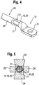
- Fig. 4 shows a perspective view of an arrangement of a first alternative electrical connection element 10 and an electrical line 20 after establishing a connection by crimping and then resistance welding a crimping section 12 of the connection element 10 with aluminum wires of the electrical line 20.
- Fig. 5 shows the arrangement of Fig. 4 during a resistance welding process.
- the electrical line 20 corresponds to the electrical line of Fig. 1 to 3 ,
- the electrical connection element 10 differs from the in Fig. 1 to 3 shown connecting element, that its crimp section 12 is formed by a crimp sleeve 30.
- the crimp sleeve 30 In the pre-assembly state of the connection element 10, not shown, the crimp sleeve 30 has a substantially round cross-section.
- the stripped aluminum wires 22 (FIG. Fig. 5 ) of the electric wire 20 is inserted into the crimping barrel 30 and the crimping barrel 30 is crimped by hexagonal crimping with the aluminum wires 22, thereby deforming into a mold having a substantially hexagonal cross section.
- Fig. 6a-d show a cross-sectional view of a section of a crimp section 12 of a connection element 10 according to the invention.
- This connection element 10 may be a connection element 10 of FIG Fig. 1 to 3 or a connection element 10 of 4 and 5 act with the difference that the crimping portion 12 of the connecting element 10 is provided on its the electrical line 20 facing inside 36 with a plurality of recesses 32.
- the depressions 32 can be produced, for example, by a cutting, milling, pressing or knurling process.
- the maximum width d of the recesses 32 is less than the diameter of an aluminum wire 40 (FIG. Fig. 6b-d ) of the electric wire 20.
- projections 34 of the crimping section 12 which have a substantially pyramidal or truncated pyramidal shape.
- Fig. 6b shows the section of Fig. 6a After the crimping portion 12 of the terminal 10 has been crimped with the aluminum wire 40. As shown, the material of the aluminum wire 40 is partially forced into the recess 32.
- Fig. 6c shows the section of Fig. 6a and Fig. 6b after heating of connection element 10 and aluminum wire 40.
- the aluminum wire 40 expands so that the recess 32 is at least approximately completely filled by the aluminum material of the wire 40.
- Fig. 6d shows the section of Fig. 6a-c after cooling following the heating of connection element 10 and aluminum wire 40.
- the cooling is formed in the recess 32 again a free area 42, in which the aluminum wire 40 can expand at a renewed heating.
- connection element 10 As in Fig. 6b-d, any loosening of the crimp connection due to repeated heating and cooling by the recesses 32 is effectively avoided. In this way, a good mechanical and electrical contact between the connection element 10 and the electrical line 20 is permanently ensured.
Description
Die Erfindung betrifft ein Verfahren zum Verbinden einer elektrischen Leitung mit einem elektrischen Anschlusselement.The invention relates to a method for connecting an electrical line to an electrical connection element.
Elektrische Leitungen, insbesondere solche, die in Fahrzeugen zur Stromversorgung oder zur Übertragung von elektrischen Steuersignalen eingesetzt werden, sind herkömmlicherweise aus Kupfermaterial gebildet und mit elektrischen Anschlusselementen aus Kupfermaterial verbunden, welche den Anschluss der elektrischen Leitungen an Fahrzeugkomponenten erleichtern.Electrical lines, in particular those used in vehicles for power supply or for the transmission of electrical control signals, are conventionally formed of copper material and connected to electrical connection elements made of copper material, which facilitate the connection of the electrical lines to vehicle components.
Aufgrund der höheren gewichtsbezogenen elektrischen Leitfähigkeit von Aluminium im Vergleich zu Kupfer ist es wünschenswert, an Stelle einer Kupferleitung eine elektrische Leitung aus Aluminium zu verwenden.Because of the higher weight electrical conductivity of aluminum compared to copper, it is desirable to use an aluminum electrical conduit instead of a copper conduit.
Bei der Verwendung einer solchen elektrischen Leitung aus Aluminium besteht jedoch das Problem, dass mit herkömmlichen Verbindungsverfahren keine Verbindung zwischen der elektrischen Leitung und einem elektrischen Anschlusselement aus einem von dem Material der elektrischen Leitung verschiedenen Metallmaterial, wie beispielsweise Kupfer, hergestellt werden kann, die dauerhaft sowohl mechanisch stabil als auch ausreichend elektrisch leitfähig ist.However, in the use of such an aluminum electrical wire, there is a problem that, with conventional joining methods, no connection between the electric wire and an electric terminal can be made of a metal material other than the electric wire material, such as copper, which is durable both mechanically stable and sufficiently electrically conductive.
Dieses Problem ist zum einen darin begründet, dass Aluminium an seiner Oberfläche eine elektrisch relativ gut isolierende Oxidschicht ausbildet, wenn es der Umgebungsluft ausgesetzt ist. Eine solche Oxidschicht erhöht den elektrischen Widerstand zwischen der elektrischen Leitung und dem elektrischen Anschlusselement. Zum anderen weist Aluminium einen deutlich höheren thermischen Ausdehnungskoeffizienten als zum Beispiel Kupfer auf, weshalb nach wiederholtem Erwärmen und Abkühlen eine Lockerung der Verbindung zwischen der elektrischen Leitung und dem Anschlusselement auftreten kann, wodurch sowohl die mechanische Stabilität als auch die elektrische Leitfähigkeit der Verbindung mit der Zeit abnimmt. Außerdem ist Aluminium prinzipiell weicher als beispielsweise Kupfer, weshalb es schwierig ist, eine Verbindung herzustellen, die eine ausreichende Zugfestigkeit aufweist. Insbesondere kann sich Aluminium durch Fließen verformen, wenn es einer Zugbelastung ausgesetzt wird, was zu einer Beeinträchtigung der Stabilität der Verbindung beiträgt.This problem is due to the fact that aluminum forms on its surface an electrically relatively well insulating oxide layer, when exposed to the ambient air. Such an oxide layer increases the electrical resistance between the electrical line and the electrical connection element. On the other hand, aluminum has a significantly higher coefficient of thermal expansion than, for example, copper, and therefore, after repeated heating and cooling, a loosening of the connection between the electrical line and the connection element can occur, as a result of which both the mechanical stability and the electrical conductivity of the connection with time decreases. In addition, aluminum is in principle softer than, for example, copper, which is why it is difficult to produce a compound which has sufficient tensile strength. In particular, aluminum may deform by flow when subjected to tensile loading, thereby contributing to impairing the stability of the joint.
Der Erfindung liegt die Aufgabe zugrunde, ein Verfahren zu schaffen, mit dem eine dauerhaft mechanisch stabile und elektrisch leitfähige Verbindung zwischen einer elektrischen Leitung mit mindestens einem Aluminiumdraht und einem Anschlusselement aus einem von dem Material des Aluminiumdrahts verschiedenen Metallmaterial hergestellt werden kann.The invention has for its object to provide a method with which a permanently mechanically stable and electrically conductive connection between an electrical line with at least one aluminum wire and a terminal made of a metal material other than the material of the aluminum wire.
Zur Lösung dieser Aufgabe ist ein Verfahren mit den Merkmalen des Anspruchs 1 vorgesehen.To solve this problem, a method having the features of claim 1 is provided.
Das Verfahren nach Anspruch 1 dient zum Verbinden einer elektrischen Leitung mit einem elektrischen Anschlusselement, wobei die elektrische Leitung mindestens einen Aluminiumdraht aufweist und das Anschlusselement aus einem von dem Material des Aluminiumdrahts verschiedenen Metallmaterial gebildet ist. Das Verfahren umfasst ein Vercrimpen eines Crimpabschnitts des Anschlusselements mit dem mindestens einen Aluminiumdraht sowie zusätzlich ein Verschweißen des mit dem mindestens
einen Aluminiumdraht vercrimpten Crimpabschnitts des Anschlusselements mit dem mindestens einem Aluminiumdraht und zwar mittels Widerstandsschweißen.The method of claim 1 is for connecting an electrical line to an electrical connection element, wherein the electrical line has at least one aluminum wire and the connection element is formed from a different metal material from the material of the aluminum wire. The method comprises crimping a crimping section of the connecting element with the at least one aluminum wire, and additionally welding it to the at least one
an aluminum wire crimped crimping portion of the connecting element with the at least one aluminum wire by means of resistance welding.
Das erfindungsgemäße Verfahren kombiniert also zwei Verbindungsprozesse, nämlich das Vercrimpen des Crimpabschnitts mit dem mindestens einen Aluminiumdraht einerseits und das anschließende Widerstandsschweißen andererseits. Durch diese Kombination wird eine dauerhaft mechanisch stabile und elektrisch leitfähige Verbindung zwischen der elektrischen Leitung und dem Anschlusselement gewährleistet.The inventive method thus combines two connection processes, namely the crimping of the crimping section with the at least one aluminum wire on the one hand and the subsequent resistance welding on the other hand. This combination ensures a permanently mechanically stable and electrically conductive connection between the electrical line and the connecting element.
Indem der mindestens eine Aluminiumdraht und der Crimpabschnitt beim Vercrimpen gegeneinander gequetscht werden, wird zunächst eine mechanische Verbindung zwischen dem mindestens einen Aluminiumdraht und dem Crimpabschnitt hergestellt, die eine vorläufig ausreichende mechanische Stabilität und elektrische Leitfähigkeit aufweist. Dabei wird bereits durch das Vercrimpen eine auf dem mindestens einen Aluminiumleiter vorhandene Oxidschicht zumindest teilweise aufgebrochen und eine gewisse elektrische Leitfähigkeit zwischen der Aluminiumleitung und dem Anschlusselement erreicht.By squeezing the at least one aluminum wire and the crimping portion against each other during crimping, a mechanical connection is first made between the at least one aluminum wire and the crimping portion, which has preliminarily sufficient mechanical stability and electrical conductivity. In this case, an existing on the at least one aluminum conductor oxide layer is already at least partially broken and reaches a certain electrical conductivity between the aluminum line and the connection element by crimping.
Sofern die elektrische Leitung eine Mehrzahl von Aluminiumdrähten aufweist, werden beim Vercrimpen nicht nur die einzelnen Aluminiumdrähte mit dem Anschlusselement verquetscht, sondern die Aluminiumdrähte werden auch untereinander verquetscht, wodurch sich eine verbesserte Leitfähigkeit auch zwischen den einzelnen Aluminiumdrähten ergibt.If the electrical line has a plurality of aluminum wires, not only the individual aluminum wires are crimped with the connection element during crimping, but the aluminum wires are also squeezed together, resulting in an improved conductivity also between the individual aluminum wires.
Eine optimale mechanische Stabilität und elektrische Leitfähigkeit der Verbindung wird erfindungsgemäß schließlich dadurch erreicht, dass nach dem Vercrimpen der mit dem mindestens einen Aluminiumdraht vercrimpte Crimpabschnitt zusätzlich mit dem mindestens einen Aluminiumdraht verschweißt wird, d.h. also eine stoffschlüssige Verbindung zwischen diesen geschaffen wird. Hierbei wird dem Crimpbereich so viel elektrische Energie zugeführt, dass der mindestens eine Aluminiumdraht und das Anschlusselement in ihrem Berührungsbereich aufgeschmolzen werden und dort vorhandene Oxidschichten zumindest annähernd vollständig aufgebrochen werden, wodurch der Übergangswiderstand zwischen Anschlusselement und dem mindestens einen Aluminiumdraht noch weiter verringert wird.An optimal mechanical stability and electrical conductivity of the compound is finally achieved according to the invention in that after crimping with the at least one aluminum wire crimped crimping section is additionally welded to the at least one aluminum wire, that is, so a cohesive connection between them is created. In this case, so much electrical energy is supplied to the crimping area that the at least one aluminum wire and the connection element are melted in their contact area and existing oxide layers are at least approximately completely broken, thereby further reducing the contact resistance between the connection element and the at least one aluminum wire.
Ein besonderer Vorteil des erfindungsgemäßen Verfahrens besteht dabei darin, dass die während des Vercrimpens auf den Crimpabschnitt und den wenigstens einen Aluminiumdraht ausgeübte Crimpkraft aufgrund des zusätzlichen Verschweißens geringer sein kann als bei herkömmlichen Crimpverbindungen, bei denen nicht geschweißt wird.A particular advantage of the method according to the invention consists in the fact that the crimping force exerted during the crimping on the crimping section and the at least one aluminum wire can be lower due to the additional welding than in the case of conventional crimping connections in which no welding takes place.
Bei Verwendung einer elektrischen Leitung mit mehreren Aluminiumdrähten werden außerdem die Oxidschichten der einzelnen Drähte aufgebrochen und die Drähte zumindest teilweise miteinander verschmolzen, sodass sich zwischen den Drähten ebenfalls verringerte Übergangswiderstände und eine bessere elektrische Leitfähigkeit ergeben.In addition, when using an electrical lead with multiple aluminum wires, the oxide layers of the individual wires are broken and the wires are at least partially fused together so that there are also reduced contact resistances and better electrical conductivity between the wires.
Auf diese Weise kann durch die erfindungsgemäße Kombination von Vercrimpen und Widerstandsschweißen eine dauerhaft elektrisch leitfähige und mechanisch stabile Verbindung zwischen einer Aluminiumleitung und einem Anschlusselement hergestellt werden, das aus einem Metallmaterial gebildet ist, das sich von dem Material der Aluminiumleitung unterscheidet. Unterschiedliche Materialien können hierbei auch unterschiedliche Aluminiumlegierungen sein.In this way, by the combination of crimping and resistance welding according to the invention, a permanently electrically conductive and mechanically stable connection can be produced between an aluminum line and a connection element, which is formed from a metal material that differs from the material of the aluminum line. Different materials can also be different aluminum alloys.
Vorteilhafte Ausführungsformen des erfindungsgemäßen Verfahrens sind in den Unteransprüchen, der Beschreibung und den Zeichnungen beschrieben.Advantageous embodiments of the method according to the invention are described in the subclaims, the description and the drawings.
Gemäß einer Ausführungsform werden während des Widerstandsschweißens wenigstens zwei Elektroden an dem Anschlusselement zur Anlage gebracht und ein Stromfluss zwischen den Elektroden über das Anschlusselement und den mindestens einen Aluminiumdraht erzeugt. Hierbei ist es bevorzugt, die Elektroden während des Widerstandsschweißens nicht direkt mit dem mindestens einen Aluminiumdraht in Kontakt zu bringen. Auf diese Weise können unerwünschte Wechselwirkungen zwischen dem mindestens einen Aluminiumdraht und den Elektroden verhindert werden. Geeignete Elektroden können beispielsweise ein Wolframmaterial aufweisen.According to one embodiment, at least two electrodes are brought into contact with the connection element during resistance welding, and a current flow is generated between the electrodes via the connection element and the at least one aluminum wire. In this case, it is preferable not to bring the electrodes directly into contact with the at least one aluminum wire during resistance welding. In this way, undesirable interactions between the at least one aluminum wire and the electrodes can be prevented. Suitable electrodes may, for example, comprise a tungsten material.
Während des Widerstandsschweißens kann das Anschlusselement zwischen den Elektroden eingeklemmt werden. Hierdurch wird während des Widerstandsschweißens eine gute mechanische Stabilität der Gesamtanordnung erreicht.During resistance welding, the connection element can be clamped between the electrodes. As a result, a good mechanical stability of the overall arrangement is achieved during the resistance welding.
Während des Widerstandsschweißens kann durch die Elektroden ferner eine Klemmkraft auf das Anschlusselement ausgeübt werden, die von gleicher Größenordnung ist wie eine während des Vercrimpens auf das Anschlusselement ausgeübte Kraft. Auf diese Weise erfolgt während des Widerstandsschweißens eine zusätzliche Verpressung des Anschlusselements mit dem mindestens einen Aluminiumdraht, welche zu einer noch besseren Verbindung zwischen beiden führt.During resistance welding, a clamping force can also be exerted on the connection element by the electrodes, which is of the same order of magnitude as a force exerted on the connection element during crimping. In this way, during the resistance welding an additional compression of the connection element with the at least one aluminum wire, which leads to an even better connection between the two.
Um das Anschlusselement und den mindestens einen Aluminiumdraht während des Widerstandsschweißens noch sicherer zu halten, kann das Anschlusselement während des Widerstandsschweißens zusätzlich zwischen zwei elektrisch isolierenden Halteelementen eingeklemmt werden. Dadurch, dass die Halteelemente elektrisch isolierend ausgebildet sind, wird ein Kurzschluss zwischen den Elektroden über die Halteelemente vermieden. Besonders geeignet sind Halteelemente, die ein Keramikmaterial umfassen, da diese eine besonders hohe mechanische Stabilität bei gleichzeitig hoher elektrischer Isolationswirkung aufweisen.In order to keep the connecting element and the at least one aluminum wire during the resistance welding even safer, the Connection element are additionally clamped during resistance welding between two electrically insulating retaining elements. Because the holding elements are designed to be electrically insulating, a short circuit between the electrodes via the holding elements is avoided. Particularly suitable are holding elements which comprise a ceramic material, since they have a particularly high mechanical stability with a high electrical insulation effect.
Bevorzugt wird durch das Vercrimpen eine F-Crimpverbindung oder eine Hexagonal-Crimpverbindung gebildet.Preferably, crimping forms an F-crimp connection or a hexagonal crimp connection.
Bei der Herstellung einer F-Crimpverbindung weist der Crimpabschnitt zwei freie Crimpflügel auf, die eine Aufnahme bilden, in die der wenigstens eine Aluminiumdraht eingelegt wird, wobei die Crimpflügel beim Vercrimpen auf den Aluminiumdraht aufgepresst werden, was in der Regel für beide Crimpflügel in ein und demselben Pressvorgang erfolgt. Die beiden Crimpflügel können dabei durch einen Basisabschnitt des Crimpabschnitts verbunden und so ausgebildet sein, dass der Crimpabschnitt vor dem Vercrimpen einen im Wesentlichen U- oder V-förmigen Querschnitt annimmt. Während des Vercrimpens können die Crimpflügel so umgebogen werden, dass die freien Enden der Crimpflügel in Richtung des wenigstens einen Aluminiumdrahtes weisen und gegen den Aluminiumdraht gepresst werden.In the production of an F-crimp connection, the crimping section has two free crimping tabs, which form a receptacle into which the at least one aluminum wire is inserted, wherein the crimping tabs are crimped onto the aluminum wire during crimping, which is usually in and for both crimping tabs the same pressing process takes place. The two Crimpflügel can thereby be connected by a base portion of the crimping portion and be formed so that the crimping portion assumes a substantially U- or V-shaped cross section before crimping. During crimping, the crimped blades can be bent so that the free ends of the crimping blades point in the direction of the at least one aluminum wire and are pressed against the aluminum wire.
Bei der Herstellung einer Hexagonal-Crimpverbindung, auch Sechskantcrimp genannt, wird ein Endbereich des wenigstens einen Aluminiumdrahts in eine geschlossene Crimphülse des Crimpabschnitts eingeführt und die Crimphülse zumindest bereichsweise so zusammengepresst, dass sie einen im Wesentlichen hexagonalen Querschnitt annimmt. Hierdurch wird eine besonders robuste Crimpverbindung erreicht. Eine hexagonale Crimpverbindung kann zum Beispiel unter Verwendung einer Crimpzange mit hexagonalem Innenquerschnitt erzeugt werden.In the manufacture of a hexagonal crimp, also called hex crimp, an end portion of the at least one aluminum wire is inserted into a closed crimp barrel of the crimp portion and the crimp barrel is at least partially compressed so that it assumes a substantially hexagonal cross-section. As a result, a particularly robust crimp connection is achieved. A hexagonal Crimped connection can be produced, for example, using a crimping tool with hexagonal internal cross section.
Die Verwendung eines Crimpabschnitts mit geschlossener Crimphülse erweist sich auch deshalb als vorteilhaft, weil dadurch beim anschließenden Widerstandsschweißen auf einfache Weise sichergestellt ist, dass die auf den Crimpabschnitt aufgesetzten Elektroden nicht mit dem wenigstens einen Aluminiumdraht in direkten Kontakt kommen.The use of a crimp section with a closed crimp barrel also proves to be advantageous because it ensures in a simple manner during subsequent resistance welding that the electrodes placed on the crimp section do not come into direct contact with the at least one aluminum wire.
Außerdem weist die Crimphülse einer Hexagonal-Crimpverbindung zwei im Wesentlichen parallele und ebene Außenflächen auf, an denen die für den Widerstandsschweiß-Schritt verwendeten Elektroden besonders einfach und großflächig angelegt werden können.In addition, the crimp sleeve of a hexagonal crimp connection has two substantially parallel and flat outer surfaces on which the electrodes used for the resistance welding step can be applied in a particularly simple and large-area manner.
Erfindungsgemäß wird der Crimpabschnitt des Anschlusselements an seiner der elektrischen Leitung zugewandten Innenseite mit Vertiefungen versehen und beim Vercrimpen Material des mindestens einen Aluminiumdrahts in die Vertiefungen gedrängt. Hierdurch werden die mechanische Belastbarkeit und elektrische Leitfähigkeit der hergestellten Verbindung noch weiter verbessert und somit letztlich die Zuverlässigkeit und Lebensdauer der Verbindung noch weiter erhöht.According to the invention, the crimping section of the connecting element is provided with indentations on its inner side facing the electrical line and, when crimped, material of the at least one aluminum wire is forced into the recesses. As a result, the mechanical strength and electrical conductivity of the compound produced are further improved and thus ultimately increases the reliability and life of the compound even further.
Bevorzugt werden die Vertiefungen so ausgebildet, dass sie beim Vercrimpen nur teilweise durch das Material des mindestens einen Aluminiumdrahts ausgefüllt werden.Preferably, the recesses are formed so that they are only partially filled during crimping by the material of the at least one aluminum wire.
Die Vertiefungen gleichen eine durch die unterschiedlichen thermischen Ausdehnungskoeffizienten von Aluminium und Kupfer bedingte stärkere Ausdehnung des mindestens einen Aluminiumdrahtes im Vergleich zu dem Anschlusselement bei Erwärmung aus und können deshalb auch als Ausgleichsvertiefungen bezeichnet werden. Das Material des Aluminiumdrahtes kann sich bei einer Erwärmung in die nach dem Vercrimpen frei geblieben Bereiche der Vertiefungen ausdehnen, ohne dass das Kupfermaterial durch das sich ausdehnende Aluminium nach außen gedrückt wird. Umgekehrt ist auch bei einer Abkühlung des Aluminiums und einer entsprechenden Kontraktion ein ausreichender mechanischer und elektrischer Kontakt zu dem Anschlusselement gewährleistet, da das Aluminium zumindest bereichsweise stets mit den zwischen benachbarten Vertiefungen liegenden Vorsprüngen des Anschlusselements in Kontakt steht.The depressions are similar to a greater extent of the at least one aluminum wire due to the different thermal expansion coefficients of aluminum and copper compared to The connection element when heated and can therefore be referred to as compensation wells. The material of the aluminum wire, when heated, may expand into the areas of the recesses left free after crimping, without the copper material being forced outward by the expanding aluminum. Conversely, a sufficient mechanical and electrical contact with the connection element is ensured even with a cooling of the aluminum and a corresponding contraction, since the aluminum is always at least partially in contact with the lying between adjacent recesses protrusions of the connection element.
Im Ergebnis tragen die Vertiefungen also dazu bei, eine Lockerung der Verbindung aufgrund von Temperaturschwankungen, insbesondere aufgrund von wiederholtem Erwärmen und Abkühlen des Anschlusselements und der elektrischen Leitung, zu vermeiden und eine dauerhaft zuverlässige mechanische und elektrische Verbindung zu gewährleisten.As a result, the depressions thus contribute to avoiding a loosening of the connection due to temperature fluctuations, in particular due to repeated heating and cooling of the connection element and the electrical line, and to ensure a permanently reliable mechanical and electrical connection.
Gemäß einer vorteilhaften Weiterbildung werden die Vertiefungen in dem Crimpabschnitt durch einen Schneide-, Fräs-, Press- oder Rändelvorgang gebildet. Die Vertiefungen werden mit anderen Worten dadurch erzeugt, dass Material des Crimpabschnitts, d.h. Material des Anschlusselements selbst, entfernt oder verdrängt wird. Zwischen benachbarten Vertiefungen liegende Vorsprünge können beispielsweise eine im Wesentlichen pyramidenförmige oder pyramidenstumpfförmige Gestalt aufweisen.According to an advantageous development, the depressions in the crimping section are formed by a cutting, milling, pressing or knurling process. In other words, the recesses are created by having material of the crimping section, i. Material of the connection element itself, is removed or displaced. Protrusions lying between adjacent recesses may, for example, have a substantially pyramidal or truncated pyramidal shape.
Um zu verhindern, dass ein Aluminiumdraht vollständig in einer Vertiefung aufgenommen wird, sind die maximalen Weiten der Vertiefungen geringer als der Durchmesser eines Aluminiumdrahts gewählt.In order to prevent an aluminum wire from being completely received in a depression, the maximum widths of the depressions are chosen smaller than the diameter of an aluminum wire.
Gemäß einer weiteren Ausführungsform umfasst der Crimpabschnitt des Anschlusselements eine Plattierung aus einem ein Metall enthaltenden Material, welches zumindest ein von Aluminium und Kupfer verschiedenes Metall aufweist. Denkbar ist auch, dass die Plattierung weder Aluminium noch Kupfer enthält. Die Plattierung ist vorteilhafterweise so angeordnet, dass beim Herstellen der Verbindung das Metall enthaltende Material der Plattierung an dem mindestens einen Aluminiumdraht zur Anlage kommt, sodass im Bereich des Übergangs zwischen dem Anschlusselement und der Aluminiumleitung das Metall enthaltende Material der Plattierung direkt an den mindestens einen Aluminiumdraht angrenzt. Durch eine geeignete Wahl des Metall enthaltenden Materials können die Eigenschaften der Verbindung optimiert werden. Die Plattierung kann beispielsweise ein Zinnmaterial aufweisen, da Zinn zur Erzielung besonders geringer Übergangswiderstände zu Aluminium geeignet ist.According to another embodiment, the crimping portion of the terminal member comprises a plating of a metal-containing material having at least one metal other than aluminum and copper. It is also conceivable that the cladding contains neither aluminum nor copper. The cladding is advantageously arranged so that when the connection is made, the metal-containing material of the cladding abuts against the at least one aluminum wire, so that in the region of the transition between the connection element and the aluminum line, the metal-containing cladding material directly adjoins the at least one aluminum wire borders. By a suitable choice of the metal-containing material, the properties of the compound can be optimized. The plating may, for example, comprise a tin material, since tin is suitable for achieving particularly low contact resistances to aluminum.
Gemäß noch einer weiteren Ausführungsform wird der Crimpabschnitt des Anschlusselements nach dem Vercrimpen mit einer den Crimpabschnitt abdichtenden Versiegelung versehen. Die Versiegelung kann so ausgebildet sein, dass sie den Crimpabschnitt luftdicht und/oder wasserdicht gegen die Umgebung des Crimpabschnitts abdichtet. Eine solche Versiegelung verhindert eine Korrosion des Grenzbereichs zwischen dem Anschlusselement und der elektrischen Leitung und trägt somit zur dauerhaften Zuverlässigkeit der hergestellten Verbindung bei.According to yet another embodiment, after crimping, the crimping portion of the terminal member is provided with a seal sealing the crimping portion. The seal may be designed such that it seals the crimp section airtight and / or watertight against the surroundings of the crimp section. Such a seal prevents corrosion of the boundary between the terminal and the electric wire, thus contributing to the long-term reliability of the manufactured joint.
Die Versiegelung kann aus einem Kunststoff enthaltenden Material gebildet sein und beispielsweise ein thermoplastisches Elastomer auf Urethanbasis, ein Polyamid, ein Polyvinylchlorid, ein Polyurethan oder ein Butylkautschukmaterial umfassen. Bevorzugt umschließt die Versiegelung sowohl den Crimpabschnitt des Anschlusselements als auch einen Endbereich eines Isolationsmantels der elektrischen Leitung.The seal may be formed of a plastic-containing material and include, for example, a urethane-based thermoplastic elastomer, a polyamide, a polyvinyl chloride, a polyurethane, or a butyl rubber material. Preferably, the seal encloses both the crimping portion of the terminal member and an end portion of an insulation sheath of the electric wire.
Die Versiegelung kann durch ein Spritzgießverfahren, ein Gießverfahren oder ein Aufschäumverfahren auf den Crimpabschnitt aufgebracht werden. Alternativ kann die Versiegelung auch dadurch aufgebracht werden, dass ein Schrumpfschlauch auf die Leitung und das Anschlusselement aufgeschoben und unter Wärmezufuhr auf das Anschlusselement und die Leitung aufgeschrumpft wird. Verwendung in der Erfindung findet ein elektrisches Anschlusselement aus Metallmaterial, welches einen Crimpabschnitt umfasst, der zur Herstellung einer Crimpverbindung mit einer elektrischen Leitung mit mindestens einem Aluminiumdraht ausgebildet ist, welches aus einem von dem Material des Aluminiumdrahts verschiedenen Metallmaterial gebildet ist und welches an seiner der elektrischen Leitung zugewandten Innenseite mit mehreren Vertiefungen versehen ist, in die sich während des Vercrimpens Material des mindestens einen Aluminiumdrahts ausdehnen kann. Das erfindungsgemäße Anschlusselement ermöglicht eine dauerhaft zuverlässige Verbindung mit einer elektrischen Leitung aus Aluminium, so dass sich die voranstehend erläuterten Vorteile entsprechend erreichen lassen.The seal may be applied to the crimping section by an injection molding process, a casting process, or a foaming process. Alternatively, the seal can also be applied by a shrink tube is pushed onto the line and the connection element and shrunk while supplying heat to the connection element and the line. Use in the invention finds an electrical connection element made of metal material, which comprises a crimp section, which is formed for producing a crimp connection with an electrical line with at least one aluminum wire, which is formed of a different material of the aluminum wire material and which at its electrical Conduction-facing inner side is provided with a plurality of recesses, in which material of the at least one aluminum wire can expand during crimping. The connecting element according to the invention enables a permanently reliable connection to an electrical line made of aluminum, so that the advantages explained above can be achieved accordingly.
Nachfolgend wird die vorliegende Erfindung rein beispielhaft anhand einer vorteilhaften Ausführungsform unter Bezugnahme auf die beigefügten Zeichnungen beschrieben. Es zeigen:
- Fig. 1
- eine perspektivische Ansicht eines Crimpabschnitts eines elektrischen Anschlusselements;
- Fig. 2
- eine Querschnittsansicht des mit einer elektrischen Leitung vercrimpten Crimpabschnitts von
Fig. 1 während eines Widerstandsschweißvorgangs; - Fig. 3
- eine perspektivische Ansicht des Anschlusselements und der elektrischen Leitung von
Fig. 1 nach ihrer Crimp- und Schweißverbindung; - Fig. 4
- eine perspektivische Ansicht eines ersten alternativen Anschlusselements und einer elektrischen Leitung nach ihrer Crimp- und Schweißverbindung;
- Fig. 5
- eine Querschnittsansicht des mit der elektrischen Leitung vercrimpten Anschlusselements von
Fig. 4 während eines Widerstandsschweißvorgangs; - Fig. 6a
- eine Querschnittsansicht eines Ausschnitts eines Crimpabschnitts eines zweiten alternativen Anschlusselements;
- Fig. 6b
- die Querschnittsansicht von
Fig. 6a nach dem Vercrimpen des Crimpabschnitts mit einer elektrischen Leitung; - Fig. 6c
- die Querschnittsansicht von
Fig. 6b nach einer Erwärmung von Anschlusselement und elektrischer Leitung; und - Fig. 6d
- die Querschnittsansicht von
Fig. 6c nach einer auf die Erwärmung folgenden Abkühlung von Anschlusselement und elektrischer Leitung.
- Fig. 1
- a perspective view of a crimping portion of an electrical connection element;
- Fig. 2
- a cross-sectional view of crimped with an electrical line crimping of
Fig. 1 during a resistance welding process; - Fig. 3
- a perspective view of the connection element and the electrical line of
Fig. 1 after its crimping and welding connection; - Fig. 4
- a perspective view of a first alternative connection element and an electrical line after its crimping and welding connection;
- Fig. 5
- a cross-sectional view of the crimped with the electrical line connection element of
Fig. 4 during a resistance welding process; - Fig. 6a
- a cross-sectional view of a section of a crimping portion of a second alternative connection element;
- Fig. 6b
- the cross-sectional view of
Fig. 6a after crimping the crimping portion with an electric wire; - Fig. 6c
- the cross-sectional view of
Fig. 6b after heating of connection element and electrical line; and - Fig. 6d
- the cross-sectional view of
Fig. 6c after a subsequent heating to the cooling of the connection element and electrical line.
Zusätzlich zu den Crimpflügeln 14 umfasst der Crimpabschnitt 10 zwei Crimpzungen 18, die zum Vercrimpen des Anschlusselements 10 mit einem Isolationsmantel 24 der elektrischen Leitung 20 dienen.In addition to the
Auf der den Crimpzungen 18 entgegengesetzten Seite der Crimpflügel 14 schließt sich ein Kontaktabschnitt 21 (
Unter Bezugnahme auf
Die elektrische Leitung 20 weist mehrere zu einem Aluminiumdrahtbündel 22 zusammengefasste Aluminiumdrähte auf, wobei die Aluminiumdrähte des Bündels 22 der besseren Übersichtlichkeit halber nicht einzeln dargestellt sind. Alternativ kann die elektrische Leitung 20 auch nur einen Aluminiumdraht umfassen.The
Die elektrische Leitung 20 wird in einem Endbereich durch Entfernen eines die Aluminiumdrähte 22 umgebenden Isolationsmantels 24 abisoliert, wobei die Länge des abisolierten Bereichs bevorzugt etwas länger gewählt wird als die Länge der Crimpflügel 14 in Längsrichtung des Anschlusselements 10 gesehen. Anschließend wird die elektrische Leitung 10 so in den Crimpabschnitt 12 eingesetzt, dass die abisolierten Aluminiumdrähte 22 zwischen den Crimpflügeln 14 liegen.The
Um eine Zugentlastung der Verbindung zwischen Leitung 20 und Anschlusselement 10 zu schaffen, wird ein Endbereich des verbliebenen Isolationsmantels 24 mit den dafür vorgesehenen Crimpzungen 18 vercrimpt, wie es in
Außerdem werden die Crimpflügel 14 und die Aluminiumdrähte 22 miteinander vercrimpt, indem die Crimpflügel 14 aufeinander zu gebogen und auf die zwischen den Crimpflügeln 14 freiliegenden Aluminiumdrähte 22 gepresst werden. Bevorzugt erfolgt das Vercrimpen unter Verwendung einer entsprechend angepassten Crimpzange oder eines ähnlichen Werkzeugs. Nach dem Vercrimpen ist das Aluminiumdrahtbündel 22 in Längsrichtung gesehen zumindest abschnittsweise vollumfänglich von Material des Crimpabschnitts 12 ummantelt.In addition, the
Nach dem Vercrimpen werden die Aluminiumdrähte 22 und der Crimpabschnitt 12 durch Widerstandsschweißen miteinander verschweißt. Um eine zwischenzeitliche Lockerung der Crimpverbindung aufgrund von Temperaturschwankungen zu verhindern, erfolgt das Verschweißen bevorzugt möglichst zeitnah nach dem Vercrimpen. Zur Begrenzung von unerwünschten Temperaturschwankungen zwischen dem Vercrimpen und dem Verschweißen können außerdem eine Temperatur der Leitung 20, des Anschlusselements 10 oder der Umgebungsluft überwacht beziehungsweise zumindest annähernd konstant gehalten werden.After crimping, the
Während des Widerstandsschweißens werden zwei Elektroden 26, die beispielsweise aus einem Wolframmaterial gebildet sein können, an einer Ober- beziehungsweise Unterseite des Crimpabschnitts 12 zur Anlage gebracht. Die Elektroden 26 üben jeweils eine vorgegebene Kraft auf den Crimpabschnitt 12 aus, die in Richtung der jeweils anderen Elektrode 26 gerichtet ist, sodass das Anschlusselement 10 zwischen den Elektroden 26 eingeklemmt ist. Die Klemmkräfte können dabei so gewählt sein, dass sie eine zusätzliche Verquetschung des Crimpabschnitts 12 und der Aluminiumdrähte 22 bewirken.During resistance welding, two
Um während des Widerstandsschweißens eine korrekte Positionierung des Crimpabschnitts 12 zwischen den Elektroden 26 sicher zu stellen, werden zusätzlich zwei Halteelemente 28 seitlich an dem Crimpabschnitt 12 zur Anlage gebracht, die den Crimpabschnitt 12 einklemmen und eine Bewegung des Crimpabschnitts 12 in einer Richtung senkrecht zu der Richtung der von den Elektroden 26 ausgeübten Klemmkräfte verhindern. Die Halteelemente können aus einem elektrisch isolierenden Keramikmaterial gebildet sein.In order to ensure correct positioning of the crimping
Die elektrische Leitung 20 entspricht hierbei der elektrischen Leitung von
Das elektrische Anschlusselement 10 unterscheidet sich darin von dem in
Die maximale Weite d der Vertiefungen 32 ist geringer als der Durchmesser eines Aluminiumdrahtes 40 (
Zwischen benachbarten Vertiefungen 32 liegen Vorsprünge 34 des Crimpabschnitts 12, die eine im Wesentlichen pyramidenförmige oder pyramidenstumpfförmige Gestalt besitzen.Between
Wie in
- 1010
- Anschlusselementconnecting element
- 1212
- Crimpabschnittcrimp
- 1414
- CrimpflügelCrimpflügel
- 1818
- CrimpzungeCrimpzunge
- 2020
- elektrische Leitungelectrical line
- 2121
- KontaktabschnittContact section
- 2222
- AluminiumdrahtbündelAluminum wire bundle
- 2424
- Isolationsmantelinsulation jacket
- 2626
- Elektrodeelectrode
- 2828
- Halteelementretaining element
- 3030
- Crimphülsecrimp barrel
- 3131
- Außenflächeouter surface
- 3232
- Vertiefungdeepening
- dd
- Abstanddistance
- 3434
- Vorsprunghead Start
- 3636
- Innenseiteinside
- 4040
- Aluminiumdrahtaluminum wire
- 4242
- freier Bereichfree area
Claims (9)
- A method for connecting an electrical line (20) to an electrical connection element (10), wherein the electrical line (20) comprises at least one aluminum wire (22; 40), and the connection element (10) is formed of a metal material different from the material of the aluminum wire, comprising the steps:crimping a crimping section (12) of the connection element (10) with the at least one aluminum wire (22; 40); andwelding the crimping section (12) crimped with the at least one aluminum wire (22; 40) to the at least one aluminum wire (22; 40) using resistance welding, characterized in thatthe at least one aluminum wire (20; 40) consists of aluminum or an aluminum alloy, in that the crimping section (12) of the connection element (10) is provided with recesses (32) on its inner side (36) facing the electrical line (20), and in that during crimping, material of the at least one aluminum wire (22; 40) is pressed into the recesses (32), the maximum width (d) of the recesses (32) being less than the diameter of an aluminum wire (22; 40).
- Method according to claim 1,
characterized in that
at least two electrodes (26) are brought into abutment against the connection element (10) during resistance welding, and a current flow is produced between the electrodes (26) via the connection element (10) and the at least one aluminum wire (22; 40). - Method according to claim 2,
characterized in that
the electrodes (26) are not brought into direct contact with the at least one aluminum wire (22; 40) during resistance welding. - Method according to claim 2 or 3,
characterized in that
the connection element (10) is clamped between the electrodes (26) during resistance welding. - Method according to at least one of the preceding claims,
characterized in that
the connection element (10) is clamped between two electrically insulating holding elements (28) during resistance welding, the holding elements (28) comprising in particular a ceramic material. - Method according to at least one of the preceding claims,
characterized in that
a F-crimped connection or a hexagonal crimped connection is formed by the crimping. - Method according to at least one of the preceding claims,
characterized in that
the recesses (32) in the crimping section (12) are formed by removing or displacing material of the crimping section (12) and in particular by cutting, milling, pressing or knurling. - Method according to at least one of the preceding claims,
characterized in that
the crimping section (12) of the connection element (10) has a plating of a metal-containing material, in particular of a tin-containing material. - Method according to at least one of the preceding claims,
characterized in that
the crimping section (12) of the connection element (10) is provided, after crimping, with a seal sealing the crimping section (12).
Priority Applications (1)
| Application Number | Priority Date | Filing Date | Title |
|---|---|---|---|
| EP10002028.8A EP2362491B1 (en) | 2010-02-26 | 2010-02-26 | Method for connecting an electrical conduit with an electrical connection element |
Applications Claiming Priority (1)
| Application Number | Priority Date | Filing Date | Title |
|---|---|---|---|
| EP10002028.8A EP2362491B1 (en) | 2010-02-26 | 2010-02-26 | Method for connecting an electrical conduit with an electrical connection element |
Publications (2)
| Publication Number | Publication Date |
|---|---|
| EP2362491A1 EP2362491A1 (en) | 2011-08-31 |
| EP2362491B1 true EP2362491B1 (en) | 2017-10-04 |
Family
ID=42315389
Family Applications (1)
| Application Number | Title | Priority Date | Filing Date |
|---|---|---|---|
| EP10002028.8A Not-in-force EP2362491B1 (en) | 2010-02-26 | 2010-02-26 | Method for connecting an electrical conduit with an electrical connection element |
Country Status (1)
| Country | Link |
|---|---|
| EP (1) | EP2362491B1 (en) |
Cited By (3)
| Publication number | Priority date | Publication date | Assignee | Title |
|---|---|---|---|---|
| DE102017215970B3 (en) | 2017-09-11 | 2018-07-26 | Strunk Connect automated solutions GmbH & Co. KG | Method for connecting an aluminum electrical line to an aluminum tube |
| DE102021102088B3 (en) | 2021-01-29 | 2022-07-07 | Strunk Connect automated solutions GmbH & Co. KG | Method for connecting an aluminum electrical cable to a connecting element made from a dissimilar metal material |
| DE102021125134B3 (en) | 2021-09-28 | 2023-02-02 | Strunk Connect automated solutions GmbH & Co. KG | Process for welding an aluminum electrical cable to a connection element made from a dissimilar metal material |
Families Citing this family (11)
| Publication number | Priority date | Publication date | Assignee | Title |
|---|---|---|---|---|
| AT513003B1 (en) * | 2012-06-06 | 2014-05-15 | Gebauer & Griller | Connection of an electrical cable with a contact part |
| DE102013203166B4 (en) * | 2013-02-26 | 2020-01-30 | Kiekert Ag | Bowden |
| DE102013215686A1 (en) * | 2013-08-08 | 2015-02-12 | Continental Automotive Gmbh | Wire and method for making a stranded wire |
| CN103441615B (en) * | 2013-08-20 | 2015-10-28 | 广东美芝精密制造有限公司 | Wire connections and method of attachment |
| DE102013219150A1 (en) * | 2013-09-24 | 2015-04-09 | Elringklinger Ag | Method for producing an electrically conductive connection between an electrical line and an electrically conductive component |
| DE102014006244A1 (en) * | 2014-04-28 | 2015-10-29 | Rosenberger Hochfrequenztechnik Gmbh & Co. Kg | Crimp weld |
| DE102016125897B4 (en) | 2016-02-11 | 2022-06-23 | Few Fahrzeugelektrikwerk Gmbh & Co. Kg | Solderable electrical connection element |
| EP3490069B1 (en) * | 2017-11-23 | 2020-07-15 | A.E.C. S.r.l. | Power terminal |
| EP3984682A1 (en) * | 2020-10-19 | 2022-04-20 | TE Connectivity Germany GmbH | Device and method for compact embedded wire welding using a shape-forming electrode |
| DE102021109175A1 (en) | 2021-04-13 | 2022-10-13 | Olympus Winter & Ibe Gmbh | Electrode instrument, surgical hand device and their manufacturing process |
| DE102021129706A1 (en) | 2021-11-15 | 2023-05-17 | Strunk Connect automated solutions GmbH & Co. KG | Method of connecting an aluminum electrical wire to a copper tube |
Family Cites Families (6)
| Publication number | Priority date | Publication date | Assignee | Title |
|---|---|---|---|---|
| DE19821630C1 (en) * | 1998-05-14 | 1999-09-16 | Gerhard Ziemek | Crimped electrical conductor termination for use in automobile electrical connections e.g. for battery cable |
| DE19902405B4 (en) * | 1999-01-22 | 2005-10-27 | Feindrahtwerk Adolf Edelhoff Gmbh & Co | Method for producing a corrosion-resistant, electrical connection |
| DE10123636B4 (en) * | 2001-05-08 | 2009-01-29 | Prettl, Rolf | Press-welded connection, method for producing a press-welded connection and press-welding device |
| DE102006010622B3 (en) * | 2006-03-08 | 2007-08-02 | Schulte & Co. Gmbh | Connecting copper battery terminal to aluminum cable, inserts stripped cable into terminal bush and injects molten zinc through radial bore to encapsulate conductor |
| DE202007013957U1 (en) * | 2007-04-23 | 2007-12-20 | Kromberg & Schubert Gmbh & Co. Kg | Ladder with contact part |
| JP5400318B2 (en) * | 2008-04-15 | 2014-01-29 | 矢崎総業株式会社 | Crimp terminal for aluminum wire |
-
2010
- 2010-02-26 EP EP10002028.8A patent/EP2362491B1/en not_active Not-in-force
Non-Patent Citations (1)
| Title |
|---|
| None * |
Cited By (7)
| Publication number | Priority date | Publication date | Assignee | Title |
|---|---|---|---|---|
| DE102017215970B3 (en) | 2017-09-11 | 2018-07-26 | Strunk Connect automated solutions GmbH & Co. KG | Method for connecting an aluminum electrical line to an aluminum tube |
| EP3454420A1 (en) | 2017-09-11 | 2019-03-13 | Strunk Connect Automated Solutions GmbH & Co. KG | Method for connecting an electrical aluminium conduit with an aluminium pipe |
| US11038312B2 (en) | 2017-09-11 | 2021-06-15 | Strunk Connect automated solutions GmbH & Co. KG | Method for connecting an aluminum electrical wire with an aluminum tube |
| DE102021102088B3 (en) | 2021-01-29 | 2022-07-07 | Strunk Connect automated solutions GmbH & Co. KG | Method for connecting an aluminum electrical cable to a connecting element made from a dissimilar metal material |
| WO2022161929A1 (en) | 2021-01-29 | 2022-08-04 | Strunk Connect automated solutions GmbH & Co. KG | Method for connecting an electrical aluminium line to a connection element made of a metal material of a different kind |
| DE102021125134B3 (en) | 2021-09-28 | 2023-02-02 | Strunk Connect automated solutions GmbH & Co. KG | Process for welding an aluminum electrical cable to a connection element made from a dissimilar metal material |
| WO2023052383A2 (en) | 2021-09-28 | 2023-04-06 | Strunk Connect automated solutions GmbH & Co. KG | Method for welding an electric aluminium line to a connection element made of a different kind of metal material |
Also Published As
| Publication number | Publication date |
|---|---|
| EP2362491A1 (en) | 2011-08-31 |
Similar Documents
| Publication | Publication Date | Title |
|---|---|---|
| EP2362491B1 (en) | Method for connecting an electrical conduit with an electrical connection element | |
| DE102005016235B4 (en) | Wire Press Clamping and Terminal Wire Connection | |
| EP3602690B1 (en) | Connection of a connection part to a stranded wire | |
| EP3189561B1 (en) | Crimp contact | |
| EP2553766B1 (en) | Method for prefabricating cables and prefabricated cable | |
| DE112012003097B4 (en) | Electrical wire with connection and manufacturing process therefor | |
| DE10360614A1 (en) | Connection of grounding terminal and wire in vehicle comprises reducing wall of wire joint after inserting wire for making adhesive inside wire joint to permeate by side of electrical contact of terminal | |
| EP2141771A1 (en) | Contacting of light metal conductors | |
| EP3506431B1 (en) | Line connector and method for producing an electrical connection | |
| DE102018119844B4 (en) | Electrical connection and method of making an electrical connection | |
| EP2371036B1 (en) | Electrical contact connection and method for producing an electrical contact connection | |
| DE112010002631T5 (en) | Method for producing an electrical cable with a connection | |
| DE19727314B4 (en) | crimp | |
| EP3609023B1 (en) | Method and device for making an electrical connection and an electrical line | |
| EP2596552A1 (en) | Crimping sleeve for crimped connections | |
| DE102010009284B4 (en) | Conduction unit with sealing function | |
| EP3966899A1 (en) | Electrical connection console for a motor-vehicle electrical system conductor | |
| DE3729490C3 (en) | Electrical connecting element and method for connecting electrical wires | |
| EP3454420B1 (en) | Method for connecting an electrical aluminium conduit with an aluminium pipe | |
| DE102014004127B4 (en) | Method for connecting an electrical line to a metallic contact element, connecting element and sonotrode | |
| AT516232B1 (en) | Method for connecting a cable end to a connecting element | |
| DE102007047436B4 (en) | Crimping with center recess | |
| EP3771042A1 (en) | Production of a flat connection between an electrical conductor and a contact piece | |
| EP3883064B1 (en) | Connector and socket for aluminium power cable and aluminium power cable with a connector or a socket | |
| EP3560766B1 (en) | Cable assembly for an electrical network of a motor vehicle |
Legal Events
| Date | Code | Title | Description |
|---|---|---|---|
| PUAI | Public reference made under article 153(3) epc to a published international application that has entered the european phase |
Free format text: ORIGINAL CODE: 0009012 |
|
| 17P | Request for examination filed |
Effective date: 20110511 |
|
| AK | Designated contracting states |
Kind code of ref document: A1 Designated state(s): AT BE BG CH CY CZ DE DK EE ES FI FR GB GR HR HU IE IS IT LI LT LU LV MC MK MT NL NO PL PT RO SE SI SK SM TR |
|
| AX | Request for extension of the european patent |
Extension state: AL BA RS |
|
| GRAP | Despatch of communication of intention to grant a patent |
Free format text: ORIGINAL CODE: EPIDOSNIGR1 |
|
| INTG | Intention to grant announced |
Effective date: 20170502 |
|
| GRAS | Grant fee paid |
Free format text: ORIGINAL CODE: EPIDOSNIGR3 |
|
| GRAA | (expected) grant |
Free format text: ORIGINAL CODE: 0009210 |
|
| AK | Designated contracting states |
Kind code of ref document: B1 Designated state(s): AT BE BG CH CY CZ DE DK EE ES FI FR GB GR HR HU IE IS IT LI LT LU LV MC MK MT NL NO PL PT RO SE SI SK SM TR |
|
| REG | Reference to a national code |
Ref country code: GB Ref legal event code: FG4D Free format text: NOT ENGLISH |
|
| REG | Reference to a national code |
Ref country code: CH Ref legal event code: EP |
|
| REG | Reference to a national code |
Ref country code: AT Ref legal event code: REF Ref document number: 934817 Country of ref document: AT Kind code of ref document: T Effective date: 20171015 |
|
| REG | Reference to a national code |
Ref country code: IE Ref legal event code: FG4D Free format text: LANGUAGE OF EP DOCUMENT: GERMAN |
|
| REG | Reference to a national code |
Ref country code: DE Ref legal event code: R096 Ref document number: 502010014211 Country of ref document: DE |
|
| REG | Reference to a national code |
Ref country code: NL Ref legal event code: MP Effective date: 20171004 |
|
| REG | Reference to a national code |
Ref country code: LT Ref legal event code: MG4D |
|
| REG | Reference to a national code |
Ref country code: FR Ref legal event code: PLFP Year of fee payment: 9 |
|
| PG25 | Lapsed in a contracting state [announced via postgrant information from national office to epo] |
Ref country code: NL Free format text: LAPSE BECAUSE OF FAILURE TO SUBMIT A TRANSLATION OF THE DESCRIPTION OR TO PAY THE FEE WITHIN THE PRESCRIBED TIME-LIMIT Effective date: 20171004 |
|
| PG25 | Lapsed in a contracting state [announced via postgrant information from national office to epo] |
Ref country code: NO Free format text: LAPSE BECAUSE OF FAILURE TO SUBMIT A TRANSLATION OF THE DESCRIPTION OR TO PAY THE FEE WITHIN THE PRESCRIBED TIME-LIMIT Effective date: 20180104 Ref country code: LT Free format text: LAPSE BECAUSE OF FAILURE TO SUBMIT A TRANSLATION OF THE DESCRIPTION OR TO PAY THE FEE WITHIN THE PRESCRIBED TIME-LIMIT Effective date: 20171004 Ref country code: FI Free format text: LAPSE BECAUSE OF FAILURE TO SUBMIT A TRANSLATION OF THE DESCRIPTION OR TO PAY THE FEE WITHIN THE PRESCRIBED TIME-LIMIT Effective date: 20171004 Ref country code: SE Free format text: LAPSE BECAUSE OF FAILURE TO SUBMIT A TRANSLATION OF THE DESCRIPTION OR TO PAY THE FEE WITHIN THE PRESCRIBED TIME-LIMIT Effective date: 20171004 Ref country code: ES Free format text: LAPSE BECAUSE OF FAILURE TO SUBMIT A TRANSLATION OF THE DESCRIPTION OR TO PAY THE FEE WITHIN THE PRESCRIBED TIME-LIMIT Effective date: 20171004 |
|
| PG25 | Lapsed in a contracting state [announced via postgrant information from national office to epo] |
Ref country code: LV Free format text: LAPSE BECAUSE OF FAILURE TO SUBMIT A TRANSLATION OF THE DESCRIPTION OR TO PAY THE FEE WITHIN THE PRESCRIBED TIME-LIMIT Effective date: 20171004 Ref country code: BG Free format text: LAPSE BECAUSE OF FAILURE TO SUBMIT A TRANSLATION OF THE DESCRIPTION OR TO PAY THE FEE WITHIN THE PRESCRIBED TIME-LIMIT Effective date: 20180104 Ref country code: GR Free format text: LAPSE BECAUSE OF FAILURE TO SUBMIT A TRANSLATION OF THE DESCRIPTION OR TO PAY THE FEE WITHIN THE PRESCRIBED TIME-LIMIT Effective date: 20180105 Ref country code: HR Free format text: LAPSE BECAUSE OF FAILURE TO SUBMIT A TRANSLATION OF THE DESCRIPTION OR TO PAY THE FEE WITHIN THE PRESCRIBED TIME-LIMIT Effective date: 20171004 Ref country code: IS Free format text: LAPSE BECAUSE OF FAILURE TO SUBMIT A TRANSLATION OF THE DESCRIPTION OR TO PAY THE FEE WITHIN THE PRESCRIBED TIME-LIMIT Effective date: 20180204 |
|
| REG | Reference to a national code |
Ref country code: DE Ref legal event code: R097 Ref document number: 502010014211 Country of ref document: DE |
|
| PG25 | Lapsed in a contracting state [announced via postgrant information from national office to epo] |
Ref country code: SK Free format text: LAPSE BECAUSE OF FAILURE TO SUBMIT A TRANSLATION OF THE DESCRIPTION OR TO PAY THE FEE WITHIN THE PRESCRIBED TIME-LIMIT Effective date: 20171004 Ref country code: EE Free format text: LAPSE BECAUSE OF FAILURE TO SUBMIT A TRANSLATION OF THE DESCRIPTION OR TO PAY THE FEE WITHIN THE PRESCRIBED TIME-LIMIT Effective date: 20171004 Ref country code: CZ Free format text: LAPSE BECAUSE OF FAILURE TO SUBMIT A TRANSLATION OF THE DESCRIPTION OR TO PAY THE FEE WITHIN THE PRESCRIBED TIME-LIMIT Effective date: 20171004 Ref country code: DK Free format text: LAPSE BECAUSE OF FAILURE TO SUBMIT A TRANSLATION OF THE DESCRIPTION OR TO PAY THE FEE WITHIN THE PRESCRIBED TIME-LIMIT Effective date: 20171004 |
|
| PLBE | No opposition filed within time limit |
Free format text: ORIGINAL CODE: 0009261 |
|
| STAA | Information on the status of an ep patent application or granted ep patent |
Free format text: STATUS: NO OPPOSITION FILED WITHIN TIME LIMIT |
|
| PG25 | Lapsed in a contracting state [announced via postgrant information from national office to epo] |
Ref country code: SM Free format text: LAPSE BECAUSE OF FAILURE TO SUBMIT A TRANSLATION OF THE DESCRIPTION OR TO PAY THE FEE WITHIN THE PRESCRIBED TIME-LIMIT Effective date: 20171004 Ref country code: IT Free format text: LAPSE BECAUSE OF FAILURE TO SUBMIT A TRANSLATION OF THE DESCRIPTION OR TO PAY THE FEE WITHIN THE PRESCRIBED TIME-LIMIT Effective date: 20171004 Ref country code: RO Free format text: LAPSE BECAUSE OF FAILURE TO SUBMIT A TRANSLATION OF THE DESCRIPTION OR TO PAY THE FEE WITHIN THE PRESCRIBED TIME-LIMIT Effective date: 20171004 Ref country code: PL Free format text: LAPSE BECAUSE OF FAILURE TO SUBMIT A TRANSLATION OF THE DESCRIPTION OR TO PAY THE FEE WITHIN THE PRESCRIBED TIME-LIMIT Effective date: 20171004 |
|
| 26N | No opposition filed |
Effective date: 20180705 |
|
| REG | Reference to a national code |
Ref country code: CH Ref legal event code: PL |
|
| PG25 | Lapsed in a contracting state [announced via postgrant information from national office to epo] |
Ref country code: MC Free format text: LAPSE BECAUSE OF FAILURE TO SUBMIT A TRANSLATION OF THE DESCRIPTION OR TO PAY THE FEE WITHIN THE PRESCRIBED TIME-LIMIT Effective date: 20171004 Ref country code: MT Free format text: LAPSE BECAUSE OF FAILURE TO SUBMIT A TRANSLATION OF THE DESCRIPTION OR TO PAY THE FEE WITHIN THE PRESCRIBED TIME-LIMIT Effective date: 20171004 |
|
| REG | Reference to a national code |
Ref country code: IE Ref legal event code: MM4A |
|
| REG | Reference to a national code |
Ref country code: BE Ref legal event code: MM Effective date: 20180228 |
|
| PG25 | Lapsed in a contracting state [announced via postgrant information from national office to epo] |
Ref country code: SI Free format text: LAPSE BECAUSE OF FAILURE TO SUBMIT A TRANSLATION OF THE DESCRIPTION OR TO PAY THE FEE WITHIN THE PRESCRIBED TIME-LIMIT Effective date: 20171004 Ref country code: CH Free format text: LAPSE BECAUSE OF NON-PAYMENT OF DUE FEES Effective date: 20180228 Ref country code: LU Free format text: LAPSE BECAUSE OF NON-PAYMENT OF DUE FEES Effective date: 20180226 Ref country code: LI Free format text: LAPSE BECAUSE OF NON-PAYMENT OF DUE FEES Effective date: 20180228 |
|
| REG | Reference to a national code |
Ref country code: DE Ref legal event code: R081 Ref document number: 502010014211 Country of ref document: DE Owner name: APTIV TECHNOLOGIES LIMITED, BB Free format text: FORMER OWNER: DELPHI TECHNOLOGIES, INC., TROY, MICH., US |
|
| PG25 | Lapsed in a contracting state [announced via postgrant information from national office to epo] |
Ref country code: IE Free format text: LAPSE BECAUSE OF NON-PAYMENT OF DUE FEES Effective date: 20180226 |
|
| REG | Reference to a national code |
Ref country code: GB Ref legal event code: 732E Free format text: REGISTERED BETWEEN 20190117 AND 20190123 |
|
| REG | Reference to a national code |
Ref country code: GB Ref legal event code: 732E Free format text: REGISTERED BETWEEN 20190124 AND 20190130 |
|
| PG25 | Lapsed in a contracting state [announced via postgrant information from national office to epo] |
Ref country code: BE Free format text: LAPSE BECAUSE OF NON-PAYMENT OF DUE FEES Effective date: 20180228 |
|
| REG | Reference to a national code |
Ref country code: AT Ref legal event code: MM01 Ref document number: 934817 Country of ref document: AT Kind code of ref document: T Effective date: 20180226 |
|
| PG25 | Lapsed in a contracting state [announced via postgrant information from national office to epo] |
Ref country code: AT Free format text: LAPSE BECAUSE OF NON-PAYMENT OF DUE FEES Effective date: 20180226 |
|
| PG25 | Lapsed in a contracting state [announced via postgrant information from national office to epo] |
Ref country code: TR Free format text: LAPSE BECAUSE OF FAILURE TO SUBMIT A TRANSLATION OF THE DESCRIPTION OR TO PAY THE FEE WITHIN THE PRESCRIBED TIME-LIMIT Effective date: 20171004 |
|
| PG25 | Lapsed in a contracting state [announced via postgrant information from national office to epo] |
Ref country code: PT Free format text: LAPSE BECAUSE OF FAILURE TO SUBMIT A TRANSLATION OF THE DESCRIPTION OR TO PAY THE FEE WITHIN THE PRESCRIBED TIME-LIMIT Effective date: 20171004 Ref country code: HU Free format text: LAPSE BECAUSE OF FAILURE TO SUBMIT A TRANSLATION OF THE DESCRIPTION OR TO PAY THE FEE WITHIN THE PRESCRIBED TIME-LIMIT; INVALID AB INITIO Effective date: 20100226 |
|
| PG25 | Lapsed in a contracting state [announced via postgrant information from national office to epo] |
Ref country code: CY Free format text: LAPSE BECAUSE OF FAILURE TO SUBMIT A TRANSLATION OF THE DESCRIPTION OR TO PAY THE FEE WITHIN THE PRESCRIBED TIME-LIMIT Effective date: 20171004 Ref country code: MK Free format text: LAPSE BECAUSE OF NON-PAYMENT OF DUE FEES Effective date: 20171004 |
|
| PGFP | Annual fee paid to national office [announced via postgrant information from national office to epo] |
Ref country code: GB Payment date: 20220221 Year of fee payment: 13 Ref country code: DE Payment date: 20220221 Year of fee payment: 13 |
|
| PGFP | Annual fee paid to national office [announced via postgrant information from national office to epo] |
Ref country code: FR Payment date: 20220215 Year of fee payment: 13 |
|
| REG | Reference to a national code |
Ref country code: DE Ref legal event code: R119 Ref document number: 502010014211 Country of ref document: DE |
|
| GBPC | Gb: european patent ceased through non-payment of renewal fee |
Effective date: 20230226 |
|
| PG25 | Lapsed in a contracting state [announced via postgrant information from national office to epo] |
Ref country code: GB Free format text: LAPSE BECAUSE OF NON-PAYMENT OF DUE FEES Effective date: 20230226 |
|
| PG25 | Lapsed in a contracting state [announced via postgrant information from national office to epo] |
Ref country code: GB Free format text: LAPSE BECAUSE OF NON-PAYMENT OF DUE FEES Effective date: 20230226 Ref country code: FR Free format text: LAPSE BECAUSE OF NON-PAYMENT OF DUE FEES Effective date: 20230228 Ref country code: DE Free format text: LAPSE BECAUSE OF NON-PAYMENT OF DUE FEES Effective date: 20230901 |