EP3050071B1 - End-hall-ionenquelle mit verbesserter strahlungskühlung - Google Patents
End-hall-ionenquelle mit verbesserter strahlungskühlung Download PDFInfo
- Publication number
- EP3050071B1 EP3050071B1 EP14849024.6A EP14849024A EP3050071B1 EP 3050071 B1 EP3050071 B1 EP 3050071B1 EP 14849024 A EP14849024 A EP 14849024A EP 3050071 B1 EP3050071 B1 EP 3050071B1
- Authority
- EP
- European Patent Office
- Prior art keywords
- pole piece
- side wall
- cup
- anode
- external pole
- Prior art date
- Legal status (The legal status is an assumption and is not a legal conclusion. Google has not performed a legal analysis and makes no representation as to the accuracy of the status listed.)
- Active
Links
Images

Classifications
-
- H—ELECTRICITY
- H01—ELECTRIC ELEMENTS
- H01J—ELECTRIC DISCHARGE TUBES OR DISCHARGE LAMPS
- H01J27/00—Ion beam tubes
- H01J27/02—Ion sources; Ion guns
- H01J27/08—Ion sources; Ion guns using arc discharge
- H01J27/14—Other arc discharge ion sources using an applied magnetic field
- H01J27/146—End-Hall type ion sources, wherein the magnetic field confines the electrons in a central cylinder
-
- H—ELECTRICITY
- H01—ELECTRIC ELEMENTS
- H01J—ELECTRIC DISCHARGE TUBES OR DISCHARGE LAMPS
- H01J2237/00—Discharge tubes exposing object to beam, e.g. for analysis treatment, etching, imaging
- H01J2237/002—Cooling arrangements
-
- H—ELECTRICITY
- H01—ELECTRIC ELEMENTS
- H01J—ELECTRIC DISCHARGE TUBES OR DISCHARGE LAMPS
- H01J27/00—Ion beam tubes
- H01J27/02—Ion sources; Ion guns
- H01J27/08—Ion sources; Ion guns using arc discharge
- H01J27/14—Other arc discharge ion sources using an applied magnetic field
Definitions
- This invention relates generally to ion and plasma sources, and more particularly it pertains to end-Hall ion sources in which ions are accelerated by a direct current discharge within a quasi-neutral plasma.
- End-Hall ion sources are used in a wide range of industrial applications. They are subject to a variety of heating and maintenance problems.
- the object of this invention is an end-Hall ion source that is easy to maintain when operated at high power.
- Ions are generated by electrons emitted from an electron emitting cathode that is operated at a potential near ground.
- Ground is defined here as the potential of the surrounding vacuum chamber, which is usually (but not always) the same as earth ground.
- the electrons are attracted to the anode, which is at a positive voltage relative to ground - from several tens of Volts positive up to several hundreds of Volts positive.
- the electrons As the electrons enter the discharge region enclosed by the anode, they gain sufficient kinetic energy to ionize atoms or molecules of the ionizable working gas.
- the electrons are prevented from directly reaching the anode by a magnetic field between the internal pole piece and the external pole piece.
- Neutralized here refers to nearly equal densities of electrons and ions, not the recombination of the electrons and ions.
- This reflector is electrically isolated and "floats" at a voltage intermediate of the anode and ground. This intermediate potential avoids the excessive erosion of the reflector that would take place if it were at ground potential, as well as the excessive loss of ionizing electrons if it were at anode potential.
- This reflector has been called a gas distribution plate or distributor, for its function in distributing the ionizable working gas. It has also been called a reflector, for its role in reflecting and conserving the ionizing electrons. It will be called a “reflector” herein.
- the ion source is enclosed by the return path for the magnetic field between the internal and external pole pieces.
- This enclosure also serves to exclude the electrons and ions that exist in the vacuum chamber outside of the ion source. These electrons and ions would otherwise cause damaging and performance-degrading arcs between electrodes inside the ion source.
- the enclosure also serves to exclude particles which would otherwise be deposited inside the ion source and result in a more rapid coating and degradation of insulators.
- the magnetic field could be generated by an electromagnet, but is usually generated by a permanent magnet adjacent to, or incorporated with, the internal pole piece.
- the energy input to the ion source is mostly from the discharge energy, that is, the current to the anode times the potential of the anode. Some additional energy is required to generate electrons, either the heating power for a hot-filament, cathode or the discharge power in a hollow-cathode type of cathode. Excessive heating can demagnetize the permanent magnet. It can also cause melting of the anode or reflector.
- Various cooling techniques have been used to avoid the problems caused by excessive heating. But these cooling techniques have often caused new problems.
- cooling lines (carrying liquid coolant) that must be opened to perform maintenance, then re-connected to resume operation, with the possibility of cooling-line leaks in the vacuum chamber from the opening and re-connecting of these lines.
- Cooling the anode directly requires voltage isolation in the cooling lines, with the added problems of degradation of the insulator used and the enhanced erosion in the cooling lines caused by the applied voltage.
- Indirect cooling of the anode involves the conduction of heat through thin layers of insulation which, depending on the insulator, are easily broken or penetrated. It can also be difficult to maintain reliable heat transfer through thin layers of insulators due to poor thermal conductivity or poor thermal contact.
- maintenance by the ion-source user can sometimes be carried out without regard for the manufacturer's instructions.
- US 2005/237000 A1 discusses direct cooling of an anode in an end-Hall ion source.
- a specific object of the invention is to provide an end-Hall ion source that does not require the opening of coolant lines to perform maintenance on the ion source.
- Another specific object of the invention is to provide an end-Hall ion source that does not require additional thin layers of material between parts to enhance heat transfer between the parts, wherein the thin layers are easily omitted or damaged during maintenance.
- Yet another specific object of the invention is to provide an end-Hall ion source that does not require thin layers of electrical insulation between parts to electrically isolate the parts, wherein the thin layers of insulation are easily damaged during maintenance.
- Still another specific object of the invention is to provide an end-Hall ion source that does not require conduction cooling of parts at elevated electrical potentials such as the anode and reflector.
- a still further specific object of the invention is to provide an end-Hall ion source with adequate cooling of the anode and reflector at high operating power using only radiation cooling of these parts.
- Another still further specific object of the invention is to provide an end-Hall ion source in which the clamping force between heat-transfer surfaces increases as the temperatures of those parts increases.
- an end-Hall ion source has an electron emitting cathode, an anode, a reflector, an internal pole piece, an external pole piece, a magnetically permeable path, and a magnetic-field generating means located in the permeable path between the two pole pieces.
- the anode and reflector are enclosed without contact by a thermally conductive cup that has internal passages through which a cooling fluid can flow.
- the closed end of the cup is located between the reflector and the internal pole piece and the opposite end of the cup is in direct contact with the external pole piece, and wherein the cup is made of a material having a low microhardness, such as copper or aluminum.
- prior-art end-Hall ion source 100 has magnetic-field energizing means 102, which in FIG. 1 is a permanent magnet.
- the magnetic-field energizing means could also be an electromagnet, although permanent magnets are more common for this function.
- the top of permanent magnet 102 performs the function of internal pole piece 102A.
- the internal pole piece could also be a separate piece of magnetically permeable material located on top of permanent magnet 102.
- the magnetic circuit includes magnetically permeable external pole piece 104, magnetically permeable base plate 106, and magnetically permeable cylindrical wall 108.
- the magnetic circuit with the magnetic-field energizing means generates magnetic field B between internal pole piece 102A and external pole piece 104. Variations in the magnetic circuit are possible without significantly affecting magnetic field B or the performance of the ion source.
- Electron emitting means 112 is shown as a hot filament, typically a tungsten or tantalum wire. It could also be a hollow cathode, as described in U.S. Patent 7,667,379 - Kaufman, et al. It could even be a separate piece of equipment in the vacuum chamber, a magnetron for example in U.S. Patent 6,454,910 - Zhurin, et al. Between anode 110 and internal pole piece 102A is reflector 114. The reflector is also called a gas distribution plate or distributor, as mentioned in the Background section.
- Ionizable gas 116 is introduced through gas tube 118, attached to central plate 120.
- the gas flows into gas distribution volume 122, through a plurality of apertures 124 in the reflector, into recess 126 in anode 110, and then into discharge volume 128.
- electron emitting means 112 is at a potential close to ground, the potential of the surrounding vacuum chamber.
- the surrounding vacuum chamber is not shown in FIG. 1 .
- the vacuum chamber is usually (but not always) at earth ground.
- Anode 110 is at a positive potential relative to ground - from several tens of Volts positive up to several hundreds of Volts positive.
- the electrons are attracted to the positive potential of anode 110.
- the electrons are prevented from directly reaching the anode by magnetic field B generated between internal pole piece 102A and external pole piece 104.
- neutralized here refers to nearly equal densities of electrons and ions, not the recombination of the electrons and ions.
- the maximum beam energy (ion-beam current times ion-beam energy) of an end-Hall ion source is limited by heating and the damage caused by that heating. Most of the heat comes from the discharge to anode 110. A smaller amount comes from the electron emitting means 112. If the electron emitting means is a a hollow cathode, as described in the aforesaid U.S. Patent 7,667,379 by Kaufman, et al. , the heating from the electron emitting means is quite small compared to the anode discharge. In addition, the heat from the electron emitting means is radiated in all directions, with most of it going to other than the ion source.
- the useful energy is in the ion beam. It is instructive to consider the fraction of the discharge energy that leaves in the ion beam. For a typical 150 V discharge, the mean ion energy is about 90 eV (electron-Volts). This means that the ion energy is the same as if they "fell" through a potential difference of 90 V. In addition, energy was used in ionizing the working gas that leaves as ions. For the common working gas of argon, this would be 15.76 eV per ion, making a total useful energy of 105.76 eV per ion. The total ion-beam current is equal to about 20 percent of the discharge current.
- the useful energy (energy used in creating and accelerating the ions) is a 1 A ion beam times 105.76 V, or 106 W.
- the anode and reflector are cooled by radiation. Some of this radiation can escape through the central aperture in external pole piece, leaving roughly 75-80 percent of the discharge power to heat surrounding ion-source parts: external pole piece 104, cylindrical wall 108, and central plate 120. These elements in turn radiate to other ion-source elements and to the surrounding vacuum chamber.
- elements 104, 108, and 120 serve as radiation shields, thereby causing the anode and reflector temperatures to increase compared to the temperatures these parts would have if elements 104, 108, and 120 were not present.
- conduction between parts that are nominally in contact tends to be much smaller in a vacuum environment than in a normal atmospheric environment.
- the thermal conduction is a negligible process in the cooling of an end-Hall ion source.
- the damage due to operating at an excessive power can be in the form of melting for anode 110 or reflector 114.
- the magnetic-field generating means is a permanent magnet
- the magnet can also be damaged by approaching the Curie temperature, at which it is demagnetized.
- One or more of these three forms of damage typically limit the operating power of an end-Hall ion source. Which one will be the limit in a particular ion source will depend on design details for that source.
- the ion source shown in FIG. 1 has maintenance requirements. These requirements can vary with the application for which the ion source is used, but often include removing an electrically insulating coating on the anode, replacing insulators in the ion source (used to separate components that operate at different voltages) that have become coated with conducting layers, replacing an eroded reflector, and generally removing deposited films that can break loose and cause arcing and contamination of work pieces.
- the cleaning of surfaces during maintenance is often done with abrasive blasting, in which abrasive particles are blown at surfaces with compressed air. Abrasive blasting leaves a roughened surface that tends to prevent peeling of layers that are subsequently deposited. But it is often carried out by hourly workers that may do a poor job, or even abrasive blast surfaces that don't need cleaning.
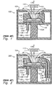
- prior-art end-Hall ion source 200 in which anode 210 is cooled directly by a fluid flowing through internal passages.
- Central plate 220 differs only in being modified to accommodate the anode cooling.
- Cooling passages 232 in anode 210 are connected to anode tubes 234, cooling isolator 236 and supply tubes 238.
- Cooling fluid 240 flows through all of these to cool anode 210.
- Anode tubes 234 and supply tubes 238 are customarily made of stainless steel to avoid contaminating the vacuum environment.
- Cooling isolator 236 is constructed of a ceramic insulator and is necessary because cooling fluid 240 is normally supplied to the ion source through tubes (in this case supply tubes 238 ) at ground potential. Cooling isolator 236 serves to electrically isolate the positive potential of anode 210 from ground potential. All other elements in FIG. 2 function as described in connection with FIG. 1 .
- FIG. 2 While the apparatus shown in FIG. 2 can be effective in cooling the anode and increasing the permissible operating power for the ion source, it also requires more routine maintenance compared to the radiation cooled design shown in FIG. 1 .
- the cooling fluid is mostly or entirely water, as it usually is, the potential difference across cooling isolator 236 tends to degrade the surfaces of the cooling isolator that are in contact with the cooling fluid.
- the ends of anode tubes 234 and supply tubes 238 closest to cooling isolator 236 are also subject to increased erosion due to the potential difference across the cooling isolator.
- supply tubes 238 must be opened to perform maintenance, then reconnected to resume operation after maintenance. The opening and reconnecting of cooling lines is always undesirable in a vacuum chamber because of the increased possibility of cooling-line leaks during a subsequent pumpdown.
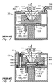
- prior-art end-Hall ion source 300 in which external pole piece 304 is cooled directly by a fluid flowing through internal passages. Cooling passages 332 in external pole piece 304 are connected to supply tubes 334. Cooling fluid 340 flows through the passages and tubes to cool external pole piece 304. All other elements in FIG. 3 function as described in connection with FIG. 1 .
- the apparatus shown in FIG. 3 can be effective in cooling the external pole piece, reducing the heat radiated to the ion-beam target from the ion source, and facilitating more rapid access to the ion source for maintenance. But the increase in permissible operating power for the ion source is much smaller than if the anode were cooled, as shown in FIG. 2 . While it avoids the tube corrosion and cooling-isolator degradation associated with the apparatus shown in FIG. 2 , it still has the shortcoming of having to open and reconnect water lines to perform maintenance on the ion source.
- FIG. 4 there is shown prior-art end-Hall ion source 400, in which the anode is cooled indirectly by conduction to a central plate that has a cooling fluid flowing through internal passages.
- This apparatus is described in U.S. Patent 7,342,236 - Burtner, et al.
- the apparatus shown in FIG. 4 corresponds to that in FIGS. 2 and 9 (FIG. 9 shows more detail) in the aforesaid U.S. Patent 7,342,236 by Burtner, et al. , and illustrates the conductive cooling of the anode through an electrically insulating layer, a central concept of the aforesaid invention.
- radiation cooling of this size of ion source is limited to discharge powers of about 1000 W.
- Direct conductive cooling of the anode, as in FIG. 2 herein, permits discharge powers as high as 3000 W.
- the objective in the aforesaid patent for this configuration ( FIG. 4 herein, FIGS. 2 and 9 therein) is to use indirect conductive cooling of the anode through a "thermally conductive, electrically insulating" layer, thereby also permitting discharge powers of 3000 W.
- the word "radiation" appears only once in the aforesaid patent, in the aforementioned first-column citation, showing the limitation on power when using radiation cooling.
- external pole piece 404 is modified slightly to accommodate screws used to improve heat transfer by clamping parts together.
- Cylindrical wall 408 is shortened slightly to accommodate the change in clamping.
- Anode 410 and reflector 414 are also modified to accommodate the change in clamping.
- Central plate 420 differs from central plate 120 by having internal passages 432 for the cooling fluid and accommodations for screw heads and threaded holes used in clamping. The supply tubes to bring and carry away the cooling fluid are not shown, but can be at ground potential and do not have to be opened and reconnected to carry out routine maintenance.
- An anode subassembly is comprised of anode 410, reflector 414, thermally conductive, electrically insulating thermal transfer interface component 442, ceramic isolator 444, a plurality of anode subassembly attachments 446 (screws), and a plurality of insulators 442.
- thermally conductive, electrically insulating thermal transfer interface component and “ceramic isolator” are used in the aforesaid U.S. Patent 7,342,236 by Burtner, et al.
- a plurality of anode subassembly attachments 446 hold the anode subassembly together, while a plurality of insulators 448 keeps the anode from touching the external pole piece when anode subassembly attachments 446 are tightened.
- the anode subassembly is then attached to the ion source with a plurality of subassembly attachments 450. (Note that "subassembly attachments" are different from “anode subassembly attachments.")
- the apparatus shown in FIG. 4 has maintenance shortcomings. These shortcomings result from poor thermal conduction across joints in vacuum, which will be described later in more detail and from a more fundamental heat-transfer viewpoint. These shortcomings are more evident in the commercial product that is based on the aforesaid U.S. Patent 7,342,236 by Burtner, et al. , and marketed by the assignee as the Mark II ⁇ Ion Source. The performance of this commercial product is described by Mahoney, et al., in an article in the 49th Annual Technical Conference Proceeding (2006) beginning on page 706 , while the maintenance of this commercial product is described in an anonymous technical manual, Manual #427366 Rev B (2006 ). Thermally conductive, electrically insulating thermal transfer interface component 442 in FIG. 4 herein becomes the "thermal transfer plate" in the aforesaid anonymous technical manual.
- thermal transfer sheets that are located on both sides of the thermal transfer plate (pages 35 and 36 in the aforesaid anonymous manual) and are described further on page 36, "The thermal transfer sheets tear easily.”
- the thermal transfer sheets are also described in U.S. Patent 7,566,883 - Burtner, et al. During reassembly, pages 41 thru 43 in the aforesaid anonymous manual, a torque wrench is required for three separate steps in reassembly.
- FIG. 4 herein and FIG. 9 of the aforesaid U.S. Patent 7,342,236 by Burtner, et al. wherein the anode is cooled indirectly by conduction, either in the configuration of the aforesaid patent or with the addition of the thermal transfer sheets as described in the aforementioned anonymous technical manual, Manual #427366 Rev B (2006 ).
- the performance of this source is described in the aforementioned article by Mahoney, et al., in the 49th Annual Technical Conference Proceeding (2006 ), and compared to both the radiation-cooled end-Hall ion source ( FIG. 1 herein) and the direct-cooled anode ( FIG. 2 herein).
- All of these ion sources have a nominal diameter of 14 cm, not counting the projection of a hollow cathode beyond the source diameter, so that there is no large difference in source size.
- the radiation-cooled source was limited to a discharge power of 875 W, due to the magnet approaching the Curie temperature where it would become demagnetized.
- Both the direct-cooled anode ( FIG. 2 herein) and the indirect-conduction-cooled anode ( FIG. 4 herein) were operated at the much higher power of 3000 W, with much lower magnet temperatures for both. There was also a switch in the electron emitting means from hot filaments to hollow cathodes for both sources when operated at 3000 W.
- the direct-cooled anode had a lower anode temperature of less than 500°C, compared to over 1000°C for the indirect-conduction-cooled anode.
- the gas distributor (called the reflector herein) showed the opposite relationship with the distributor at over 600°C for the indirect-conduction-cooled anode compared to over 1000°C for that of the direct-cooled anode.
- the disadvantages of multiple fragile layers can be balanced against the opening and reconnecting of cooling lines during maintenance.
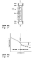
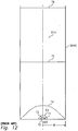
- Thermal source 502 supplies heat to first cylinder 504, while second cylinder 506 is cooled by heat sink
- the first and second cylinders meet at joint 510, where they are held in contact with force F.
- the cylindrical sides of the first and second cylinders are typically covered with insulation, so that the only significant heat transfer is parallel to the cylinders.
- temperatures T1, T2, T3, etc. are measured and plotted in FIG. 6 against distance D, which is defined herein as the distance along cylinders 504 and 506 in FIG. 5 .
- distance D is defined herein as the distance along cylinders 504 and 506 in FIG. 5 .
- the temperatures vary in a linear manner with distance D, except near joint 510, where extrapolations of the linear variations (shown by the dashed lines) give a temperature difference, ⁇ T , due to the presence of the joint. Note that the linear variations are not the same for the two cylinders in FIG. 6 , which would be expected if the cylinders are made of different materials.
- the thermal resistance at a joint varies with the force that pushes the two members together ( F in FIG. 5 ), the contours of the surfaces at the joint, the properties of the members in the joint, and the environment of the joint.
- FIGS. 7(a), 7(b), and 7(c) there are shown typical surface contours.
- the contacting elements, element 504A and element 506A meeting at joint 510A in FIG. 7(a) , element 504B and element 506B meeting at joint 510B in FIG. 7(b) , etc. are all assumed to be in a test equipment environment similar to that shown in FIG.
- FIGS. 8(a), 8(b), and 8(c) The roughness sizes are enlarged in these figures, because they would be within the width of a printed line if they were drawn to scale.
- FIG. 7(a) The smooth contours shown in FIG. 7(a) are not practical for ion sources in an industrial vacuum environment.
- the loads are light, so that only the peaks of surface asperities are in contact. Further, careless handling during maintenance frequently roughens surfaces, whether or not the parts from the ion-source manufacturer are initially polished smooth.
- FIG. 7(b) it is practical to design and fabricate parts that have conformal surfaces, as shown in FIG. 7(b) .
- FIG. 9 there is shown a view of the cross section of FIG. 7(b) that is enlarged further.
- the contact of rough conforming element 504B and element 506B results in mean separation, Y , with only occasional contact between the two elements.
- the contact between elements shown in FIG. 9 and the environment of this contact affects the heat transfer between those elements.
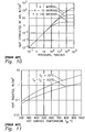
- the effect of varying the atmospheric pressure on heat transfer at a joint with several values of mean separation, Y, is shown in FIG. 10 for a hot temperature of 125°C and a cold temperature of 25°C.
- the calculation procedure used is described by Yovanovich, et al., in Chapter 4 of Heat Transfer Handbook (Bejan et al., eds.), John Wiley & Sons. Inc., Hoboken, New Jersey (2003), beginning on page 261 .
- One atmosphere is approximately 10 5 Pa (Pascals). At pressures near one atmosphere, the heat conduction is sensitive to the mean separation, Y .
- the maximum background pressure for operating an end-Hall ion source is usually about 0.1 Pa, where the heat transported is only about 10 -3 W/cm 2 for the conditions given.
- the mean separation doesn't matter at very low pressures, because the mean path length for molecules is much greater than the mean separation, and only the gas pressure is important for the heat conduction.
- the heat transfers shown in FIG. 10 will vary with the background gas and specific temperatures that are used in the heat transfer calculations. But the gas conduction of heat will remain negligible for ion-source cooling at the pressures at which ion sources operate. Conversely, it is often the gas conduction that gives the normal expectation of heat transfer at a joint in an atmospheric environment.
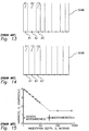
- the heat transfer at a joint due to radiation is shown for a range of hot surface temperatures.
- Two cold surface temperatures are used, one held constant at 25°C and the other varied to be 100°C colder than the hot surface.
- the calculation of these heat transfers used the Stefan-Boltzmann radiation constant, emissivities and absorptivities of 0.5 (typical of rough surfaces), and a geometric configuration with two extended parallel surfaces.
- the heat transfer should be several W/cm 2 .
- the heat transferred by radiation is only a small fraction of that value for hot surface temperatures of 500°C or less. Again, changes in the values used in the calculations for FIG. 11 would change the results, but not by enough to make radiation significant for heat transfer in an end-Hall ion source at hot-surface temperatures less than about 500°C.
- FIGS. 10 and 11 The fundamental limitations on heat transfer in vacuum are illustrated by FIGS. 10 and 11 . These results can be surprising to someone unskilled in vacuum technology.
- the gas conduction provided by an atmospheric environment in a mechanical joint is important and is missing in a vacuum environment. And, except at very high temperatures, little heat transfer takes place in a joint due to radiation.
- Unless easily damaged thermal transfer sheets are used to provide more contact area, as described in the aforesaid anonymous technical manual and the aforesaid U.S. Patent 7,566,883 - Burtner, et al. , the heat transfer at a joint in a vacuum environment is typically determined by a physical contact similar to that indicated in FIG. 9 .
- the heat flux in this cylinder represents the heat flux associated with one contact area.
- the temperature over radius A at the bottom is held at temperature T0, and represents a small thermal contact area over the same radius.
- the temperature at the top of the cylinder is T6 and there is no significant heat flow to any surface other than the top surface.
- the equal-temperature contours are concentrated near the contact area at the bottom of the cylinder where the temperature is held at T0 . This concentration means that a substantial amount of the thermal resistance in the cylinder is concentrated at the same location.
- the added thermal resistance due to the small contact area was first called the constriction resistance and later the spreading resistance, and was described by Negus, et al., in an ASME Paper No 84-HT-84 (1984 ).
- FIG. 13 there is shown a representation of one member of a heat-transfer joint, in which there are contact areas A1, A2 , A1, etc. of respective flux tubes F1, F2, F1, etc. There are variations in contact areas, the shapes of the contact areas, and the sizes of the associated flux tubes.
- shape details of the contact areas are not important, and that accurate heat-transfer calculations can be made with the use of circular contact areas of a mean size and the corresponding selection of a mean size for flux tubes.
- Equation (5) can be used for the spreading resistance associated with each of the contact areas.
- the selection of the mean values depends on fundamental assumptions for the specific model used.
- the "plastic contact model” assumes all contacts result from plastic deformation of the surfaces and corresponds to the initial clamping together of two surfaces. This model is appropriate for ion sources where parts would be expected to be reassembled after each maintenance with different micro-misalignments. Examination for the calculation procedure for this model also shows that the contact resistance is less for many small contacts, as opposed to a few large contacts.
- the microhardness that should be used is for the material with the least microhardness.
- the microhardness is related to the bulk hardness. Referring to FIG. 15 , there is shown both the bulk hardness and the microhardness of 304 stainless steel, a material that is widely used in vacuum chambers. It is necessary to use different hardness measuring techniques to measure hardness over a range of indentation depths. Vickers hardness is used for the microhardness measurements, while Brinell and Rockwell hardness measurements are used for macrohardness measurements.
- microhardness is related to the bulk hardness, but it can be much larger. Examples of microhardness and bulk hardness are given by Yovanovich et al. in the aforementioned Chapter 4 in Heat Transfer Handbook, by Yovanovich, in an article in the IEEE Transactions on Components and Packaging Technologies, Vol. 28 (2005), beginning on page 182 , and by Yovanovich, in AIAA Paper No. AIAA-2006-979 (2006 ).
- end-Hall ion source 600 an embodiment of the present invention.
- This source has a magnetic field similar to that of ion source 100 in FIG. 1 .
- magnetic-field energizing means 102 which is again a permanent magnet. As described in connection with FIG. 1 , this magnetic-field energizing means could also be an electromagnet.
- the top of permanent magnet 102 performs the function of internal pole piece 102A, but the internal pole piece could again be a separate piece of magnetically permeable material located on top of permanent magnet 102.
- the magnetic circuit includes magnetically permeable external pole piece 604, magnetically permeable base plate 106, and magnetically permeable cylindrical wall 608.
- the magnetic circuit with the magnetic-field energizing means generates magnetic field B between internal pole piece 102A and external pole piece 604.
- Ionizable gas 116 is introduced through gas tube 118, attached to central plate 620. The gas flows around reflector 614 into gas distribution volume 626, and then into discharge volume 128. This path for the ionizable gas is different from that shown in FIG. 1 , but the operation of the ion source is not affected significantly by this difference.
- the electrical operation is also similar to that of ion source 100 shown in FIG. 1 .
- the electron emitting means 112 is at a potential close to ground.
- Anode 610 is at a positive potential relative to ground - from several tens of Volts positive up to several hundreds of Volts positive.
- the electrons are attracted to the positive potential of anode 610.
- the electrons are prevented from directly reaching the anode by magnetic field B, which is generated between internal pole piece 102A and external pole piece 604.
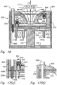
- FIG. 16 differs from the prior art in the manner of cooling, which can be called an enhanced-radiation-cooled anode.
- Central plate 620 has internal passages 632 with attached tubes 634. Cooling fluid 640 flows through tubes 634 and internal passages 632.
- Anode 610 is supported by external pole piece 604, using pluralities,of electrical insulators 642, screws 644, and nuts 646.
- reflector 614 is supported by anode 610, using pluralities of insulators 648, screws 650, and nuts 652.
- central plate 620 is cooled by cooling fluid 640, usually water, flowing through internal passages 632.
- Cylinder 654 is cooled by contact to central plate 620, and external pole piece 604 is cooled by contact with cylinder 654.
- External pole piece 604, cylinder 654, and central plate 620 are held together with a plurality of assembly units, which in this case are screws 656.
- Screws 656 are the only components that require a torque measurement. Keeping in mind the small real-to-apparent contact-area ratios that can be encountered in vacuum joints, and the associated high contact resistances, at least one of the two elements at each joint was selected to be a material with low microhardness.
- At least one of central plate 620 and cylinder 654 must be of a material with low microhardness. And at least one of cylinder 654 and external pole piece 604 must be of a material with low microhardness.
- Microhardness is described by Yovanovich in both the aforementioned article in the IEEE Transactions on Components and Packaging Technologies and in the aforementioned AIAA Paper No. AIAA-2006-979 (2006 ).
- a material with a low microhardness is defined herein as having a maximum value of Vickers microhardness, corresponding to an indentation depth of about 1 ⁇ m, of about 1 Gpa or less. Examples without limitation of materials with a low microhardness are lead, tin, silver, copper, and aluminum. Although commercially pure aluminum would also have a low microhardness, the aluminum referred to here is aluminum 6061-T6, which is a widely used alloy.
- the hot anode and hot reflector are supported by insulators with small contact areas between the insulators and the hot parts, with no special treatment of the contact areas. The result is that there is negligible conductive heat transfer from these hot parts.
- the parts surrounding the hot anode and hot reflector are cooled to enhance the radiation heat transfer from the hot parts.
- Cylinder 654 and and central plate 620 together form a thermally conductive cup that surrounds the hot anode and hot reflctor, with cylinder 654 forming the side wall of this cup and central plate 620 forming the closed end.
- Cylinder 654 is in thermal contact with and cools external pole piece 604, which completes the cooled enclosure surrounding the hot parts, except for the opening in the external pole piece for the ions to escape. Note that in the radiation-cooled configuration shown in FIG. 1 , the parts surrounding the anode and reflector are heated by the radiation and then serve as radiation shields to reduce the net radiation heat transfer. To further enhance radiation heat transfer in ion source 600, the surfaces of the anode and reflector and the surfaces of elements 604, 620, and 654 that face the anode and reflector can all be optically roughened to increase their radiation emissivities and absorptivities. The light reflected from an optically roughened does so in a diffuse, not a specular manner.
- Optically roughening can be done in different ways. It can be done mechanically by grit or abrasive blasting, in which abrasive particles are blown at the surface to be roughened with compressed air. It can also be done chemically by oxidizing the surface to be roughened. Optical roughening can increase the emissivity or absorptivity of a metal surface from 0.1-0.2 for a polished metal surface to 0.5-0.6 or even more for a roughened surface. After the heat is transferred to central plate 620, cylinder 654, and external pole piece 604, these parts are cool enough that radiation from them is negligible and the heat is essentially all carried away by the cooling fluid.
- FIG. 16 There is another feature of the embodiment of FIG. 16 that should be pointed out.
- the assembly elements that hold central plate 620, cylinder 654, and external pole piece 604 together are screws 656. These screws pass through cylinder 654 and will have approximately the same temperature as that cylinder. If the cylinder is constructed of a material with a higher coefficient of thermal expansion than the screws passing through it, the tension in the screws will increase as the temperatures of the cylinder and screws increase. This means that, if the screws are not tightened enough during assembly, and the cylinder is not cooled adequately by the central plate due to low contact pressure, the contact pressure will increase as operation is started and the cylinder heats up. This feature makes the cooling effectiveness of this embodiment less sensitive to the torques used to tighten the screws.
- FIG. 16 An example of the configuration shown in FIG. 16 was constructed using copper for central plate 620, aluminum alloy 6061-T6 for cylinder 654, and 410 stainless steel, annealed, for external pole piece 604. Thermocouples were attached to the outer edges of the anode and reflector, both sides of the central-plate/cylinder joint and both sides of the cylinder/external-pole-piece joint, as well as to the magnet and other components. Water was used as the coolant. Screws 656 were 6.35 mm in diameter and were tightened with a torque wrench to 28 kg-cm. The effectiveness of the use of low microhardness elements at heat transfer joints was shown by temperature measurements when the ion source of FIG. 16 was operated with a discharge power of 3000 W.
- Aluminum alloy cylinder 654 has a higher coefficient of thermal expansion than the plurality of 18-8 stainless steel screws 656 passing through it - about 50 percent higher. To test the effectiveness of this difference in thermal expansion coefficient in correcting for a reduction in tightening torque, the ion source was disassembled, then reassembled with a torque of only 14 kg-cm for screws 656. It was then operated at the same power described above for the higher torque. The average of the top and bottom temperatures for cylinder 654 only increased by 45°, from 125°C to 170°C. The temperature of external pole piece 604, affected both by a slightly reduced clamping force and a higher temperature for the aluminum cylinder, increased by 120°, from 260°C to 380°C.
- the temperature of the anode was, within exerimental error, the same, while the temperature of the reflector increased by only about 10°. These small differences for the anode and reflector are consistent with the small amount of energy radiated back to the anode and reflector at the temperatures of the cylinder and external pole piece. The results of this test showed a lack of sensitivity to tightening torque, which in practice can be expected to result in fewer problems and more reliable operation.
- This enhanced radiation cooling can be compared to the configuration with the indirect-conduction-cooled anode that is shown in FIG. 4 .
- the latter had an anode temperature of over 1000°C with a 3000 W discharge power and a cooler hollow-cathode electron emitter.
- the ion source shown in FIG. 16 is approximately the same diameter (14.5 cm for ion source 600 versus 14 cm for ion source 400 ) and is simpler to assemble (one tightening sequence for ion source 600 with a torque wrench versus three for ion source 400 ) without the need for fragile electrically insulating thermal transfer interface components of ion source 400 and the thermal transfer sheets of the aforementioned anonymous technical manual.
- the anode temperature is actually lower for the simpler, more rugged design of FIG. 16 .
- At least one of the two elements at a joint must be plated, brazed, or otherwise have attached to it a layer at least several tens of microns thick of material having a low microhardness.
- Lead and tin may not be suitable for constructing entire elements (e.g., central plate 620 or cylinder 654 ).
- the weaker materials may still be suitable for layers of material that are plated, brazed, welded, sputter deposited, or otherwise permanently attached to an element such as the central plate or the cylinder at a joint.
- other factors such as vapor pressure of the low microhardness material may also be important.
- FIG. 17(a) there is shown an enlarged view of a portion of an embodiment of the present invention similar to that shown in FIG. 16 , except that a layer of material having a low microhardness, layer 620B, is attached to central plate 620A.
- the layer of material having a low microhardness could have been attached instead to cylinder 654, or layers could have been attached to both the central plate and the cylinder.
- FIG. 17(b) there is shown another enlarged view of a portion of an embodiment of the present invention similar to that shown in FIG. 16 , except that a layer of material having a low microhardness, layer 654B, is attached to cylinder 654A.
- the layer of material having a low microhardness could have been attached instead to external pole piece 604, or layers could have been attached to both the cylinder and the external pole piece.
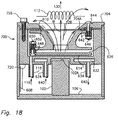
- Ion source 700 differs from ion source 600 in FIG. 16 in that cylinder 654 and central plate 620 in FIG. 16 are combined into a single integral element, thermally conductive cup 720 in FIG. 18 . Screws 756 that hold the external pole piece to this single integral element are shorter than screws 656 used in ion source 600. It also differs from ion source 600 in having a large area of external pole piece 704 (more than half the area of that side of 704 ) covered with layer 704A having higher thermal conductivity than the thermal conductivity of external pole piece 704.
- the advantage of incorporating layer 704A is that it lowers the average temperature of the radiation environment surrounding anode 610 and reflector 626, hence will reduce the temperatures of the anode and reflector.
- the thermal benefit would require a layer much thicker than a few tens of microns.
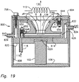
- end-Hall ion source 800 yet another alternative embodiment of the present invention.
- the cylinder and central plate are again combined into a single integral element, thermally conductive cup 820.
- the internal passages through which a cooling fluid can flow are in the cylinder part of the cup instead of the closed end.
- the cylinder and closed end form a single integral element.
- the side wall and closed end could also be separable, one from the other, with the cooling passages still in the side wall.
Landscapes
- Engineering & Computer Science (AREA)
- Chemical & Material Sciences (AREA)
- Combustion & Propulsion (AREA)
- Electron Sources, Ion Sources (AREA)
- Manufacturing & Machinery (AREA)
- Plasma Technology (AREA)
Claims (17)
- End-Hall-Ionenquellenvorrichtung, die folgendes umfasst:a) ein Mittel zur Ionenerzeugung (600), das folgendes umfasst:(i) einen Ausstoßbereich (128) mit einem ersten Ende, einem zweiten Ende und einer Seite, wobei das erste Ende offen ist;(ii) ein Elektronenemissionsmittel (112), das sich außerhalb des Ausstoßbereichs befindet;(iii) eine Anode (610), die den Ausstoßbereich an der Seite einschließt;(iv) einen Reflektor (614), der den Ausstoßbereich an dem zweiten Ende einschließt;(v) Mittel zum Einführen eines ionisierbaren Arbeitsgases in den Ausstoßbereich;b) Magnetkreismittel, die folgendes umfassen:(i) ein magnetisch durchlässiges inneres Polstück (102A), das sich außerhalb des zweiten Endes des Ausstoßbereichs und nahe dem Reflektor befindet;(ii) ein magnetisch durchlässiges und wärmeleitfähiges äußeres Polstück (604), das um das erste Ende des Ausstoßbereichs und zwischen der Anode (610) und dem Elektronenemissionsmittel (112) angeordnet ist;(iii) einen magnetisch durchlässigen Pfad zwischen dem inneren Polstück (102A) und dem äußeren Polstück (604);(iv) ein Magnetfelderzeugungsmittel (102), das sich in dem magnetisch durchlässigen Pfad befindet;gekennzeichnet durch:c) ein Kühlmittel, das eine wärmeleitfähige Schale (720, 820) umfasst, mit einem geschlossenen Ende, einer Seitenwand, einem offenen Ende und inneren Durchgängen, durch welche Fluid strömen kann; wobei die Schale die Anode und den Reflektor einschließt, ohne sich mit der Anode (610) oder dem Reflektor (614) in physischem oder elektrischem Kontakt zu befinden; wobei sich das geschlossene Ende zwischen dem Reflektor (614) und dem inneren Polstück (102A) befindet; wobei sich die Schale und das äußere Polstück (604) in physischem Kontakt miteinander befinden; und wobei wenigstens die Schale (820) oder das äußere Polystück (604) ein Material mit niedriger Mikrohärte an der Verbindungsstelle umfasst, und wobei die niedrige Mikrohärte bedeutet, dass sie einen maximalen Wert der Vickers-Mikrohärte, entsprechend einer Eindrücktiefe von etwa 1 µm, von etwa 1 Gpa oder darunter aufweist; undd) ein Montagemittel, das die Schale an dem äußeren Polstück (604) hält.
- End-Hall-Ionenquellenvorrichtung nach Anspruch 1, wobei die Schale (720, 820) eine erste Oberfläche aufweist, und wobei das äußere Polstück (604) eine zweite Oberfläche aufweist, die sich in Kontakt mit der ersten Oberfläche der Schale befindet; wobei wenigstens eine Oberfläche der ersten und der zweiten Oberfläche eine wärmeleitfähige Schicht mit niedriger Mikrohärte umfasst, die an der Verbindungsstelle dauerhaft an der Schale oder an dem äußeren Polstück angebracht ist.
- End-Hall-Ionenquellenvorrichtung nach Anspruch 1, wobei das äußere Polstück (604) eine Oberfläche aufweist, die eine wärmeleitfähige Schicht mit niedriger Mikrohärte aufweist, die dauerhaft an der Oberfläche angebracht ist; wobei das äußere Polstück (604) eine erste Wärmeleitfähigkeit aufweist; wobei die Schicht mit niedriger Mikrohärte eine zweite Wärmeleitfähigkeit aufweist, die größer ist als die erste Wärmeleitfähigkeit, und wobei die Schicht mehr als die Hälfte der Oberfläche des äußeren Polstücks bedeckt.
- End-Hall-Ionenquellenvorrichtung nach Anspruch 1, wobei das äußere Polstück (604) eine erste Mehrzahl von Löchern aufweist, die um das erste Ende des Ausstoßbereichs angeordnet sind; wobei die Seitenwand der Schale eine zweite Mehrzahl von Löchern aufweist, mit Positionen, die entsprechend den Positionen der ersten Mehrzahl von Löchern in dem äußeren Polstück entsprechen; wobei die Schale einen ersten Wärmeausdehnungskoeffizienten aufweist; wobei das Montagemittel eine Mehrzahl von Montageelementen aufweist, die einen zweiten Wärmeausdehnungskoeffizienten aufweisen und sich durch die erste und die zweite Mehrzahl von Löchern erstrecken, um das äußere Polstück in physischem Kontakt mit der Schale zu halten; wobei der erste Wärmeausdehnungskoeffizient größer ist als der zweite Wärmeausdehnungskoeffizient.
- End-Hall-Ionenquellenvorrichtung nach Anspruch 1, wobei die Seitenwand und das geschlossene Ende voneinander getrennt werden können, und wobei wenigstens die Seitenwand oder das geschlossene Ende der Schale innere Durchgänge aufweist, durch die ein Fluid strömen kann, und wobei wenigstens die Seitenwand oder das geschlossene Ende der Schale eine niedrige Mikrohärte aufweist.
- End-Hall-Ionenquellenvorrichtung nach Anspruch 5, wobei sich die Seitenwand der Schale und das äußere Polstück in physischem Kontakt befinden; wobei wenigstens eines der Seitenwand, des geschlossenen Endes und des äußere Polstücks eine niedrige Mikrohärte aufweist.
- End-Hall-Ionenquellenvorrichtung nach Anspruch 5, wobei sich die Seitenwand und das geschlossene Ende in physischem Kontakt miteinander befinden; wobei die Seitenwand eine erste Oberfläche aufweist, und wobei das äußere Polstück eine zweite Oberfläche aufweist, die sich in physischem Kontakt mit der ersten Oberfläche befindet; wobei wenigstens eine der ersten und zweiten Oberflächen eine wärmeleitfähige Schicht umfasst, die an der Verbindungsstelle daran dauerhaft angebracht worden ist; wobei die Schicht eine niedrige Mikrohärte aufweist; und wobei wenigstens die Seitenwand oder das geschlossene Ende eine niedrige Mikrohärte aufweist.
- End-Hall-Ionenquellenvorrichtung nach Anspruch 7, wobei sich die Seitenwand und das äußere Polstück (604) in physischem Kontakt miteinander befinden; wobei das geschlossene Ende eine dritte Oberfläche aufweist, die sich in Kontakt mit einer vierten Oberfläche an der Seitenwand befindet; wobei wenigstens eine der dritten oder vierten Oberfläche eine wärmeleitfähige Schicht umfasst, die an der Verbindungsstelle dauerhaft daran angebracht ist; wobei jede wärmeleitfähige Schicht eine niedrige Mikrohärte aufweist.
- End-Hall-Ionenquellenvorrichtung nach Anspruch 1, wobei das Kühlmittel eine Schale (720, 820) mit einem wärmeleitfähigen geschlossenen Ende, einer wärmeleitfähigen Seitenwand und einem offenen Ende umfasst; wobei die Seitenwand und das geschlossene Ende getrennt werden können; und wobei wenigstens die Seitenwand oder das geschlossene Ende innere Durchgänge aufweist, durch welche ein Fluid strömen kann; wobei die Schale die Anode (610) und den Reflektor (614) einschließt, ohne sich mit der Anode oder dem Reflektor in physischem oder elektrischem Kontakt zu befinden; wobei sich das geschlossene Ende zwischen dem Reflektor (614) und dem inneren Polstück (102A) befindet; wobei sich die Seitenwand und das geschlossene Ende in physischem Kontakt miteinander befinden, wobei wenigstens das geschlossene Ende oder die Seitenwand eine niedrige Mikrohärte aufweist; wobei das äußere Polstück (604) eine Oberfläche aufweist, die zu der Schale ausgerichtet ist, und wobei die Oberfläche an der Verbindungsstelle eine wärmeleitfähige Schicht mit einer niedrigen Mikrohärte umfasst; wobei die Schicht dauerhaft an dem äußeren Polstück angebracht ist und mehr als die Hälfte der Oberfläche des äußeren Polstücks bedeckt, die zu der Schale ausgerichtet ist; wobei die Schicht eine zweite Wärmeleitfähigkeit aufweist, die größer ist als die erste Wärmeleitfähigkeit; und
wobei das Montagemittel das geschlossene Ende der Schale an der Seitenwand der Schale hält und die Seitenwand der Schale an dem äußeren Polstück hält. - End-Hall-Ionenquellenvorrichtung nach Anspruch 4, wobei die Seitenwand der Schale (720, 820) den ersten Wärmeausdehnungskoeffizienten aufweist; wobei sie ferner eine dritte Mehrzahl von Löchern in dem geschlossenen Ende umfasst, deren Positionen den entsprechenden Positionen der zweiten Mehrzahl von Löchern entsprechen; wobei sich die Seitenwand und das äußere Polstück in physischem Kontakt miteinander befinden; wobei sich die Seitenwand und das geschlossene Ende in physischem Kontakt miteinander befinden; wobei die sich die Mehrzahl von Montageelementen durch die erste, zweite und dritte Mehrzahl von Löchern in dem äußeren Polstück, der Seitenwand und dem geschlossenen Ende der Schale erstrecken, um das äußere Polstück, die Seitenwand und das geschlossene Ende in physischem Kontakt zusammen zu halten.
- End-Hall-Ionenquellenvorrichtung nach Anspruch 1, wobei eine oder mehrere der Vorrichtungen der Anode oder des Reflektors optisch aufgeraut sind.
- End-Hall-Ionenquellenvorrichtung nach Anspruch 1, wobei die Oberflächen des äußeren Polstücks der Schale, die zu der Anode (610) und dem Reflektor (614) ausgerichtet sind, optisch aufgeraut sind.
- Verfahren zur Gestaltung einer End-Hall-Ionenquelle, wobei das Verfahren die folgenden Schritte umfasst:Bereitstellen eines Ausstoßbereichs mit einem ersten Ende, einem zweiten Ende und einer Seite, wobei das erste Ende offen gelassen wird;Bereitstellen eines Elektronenemissionsmittels und Anordnen des Mittels außerhalb des Ausstoßbereichs;Bereitstellen einer Anode und Einschließen des Ausstoßbereichs an der Seite durch die Anode;Bereitstellen eines Reflektors und Einschließen des Ausstoßbereichsan dem zweiten Ende durch den Reflektor;Bereitstellen eines Mittels zum Einführen eines ionisierbaren Gases in den Ausstoßbereich;Bereitstellen eines magnetisch durchlässigen inneren Polstücks und Anordnen des Polstücks außerhalb des zweiten Endes des Ausstoßbereichs und in der Nähe des Reflektors;Bereitstellen eines magnetisch durchlässigen und wärmeleitfähigen äußeren Polstücks und Anordnen des Polstücks um das erste Ende des Ausstoßbereichs und zwischen der Anode und dem Elektronenemissionsmittel;Bereitstellen eines magnetisch durchlässigen Pfads zwischen dem inneren Polstück und dem äußeren Polstück;Bereitstellen eines Magnetfelderzeugungsmittels und Anordnen des Mittels in dem magnetisch durchlässigen Pfad;Bereitstellen einer wärmeleitfähigen Schale mit niedriger Mikrohärte, wobei die niedrige Mikrohärte bedeutet, dass sie einen maximalen Wert der Vickers-Mikrohärte, entsprechend einer Eindrücktiefe von etwa 1 µm, von etwa 1 Gpa oder darunter aufweist;mit einem offenen Ende, einer Seitenwand und einem geschlossenen ende und mit inneren Durchgängen, durch welche ein Fluid strömen kann; (k) Anordnen der Schale mit dem geschlossenen Ende zwischen dem Reflektor und dem inneren Polstück, ohne einen physischen oder elektrischen Kontakt mit der Anode oder dem Reflektor, wobei die Seitenwand die Anode einschließt und sich in Kontakt mit dem äußeren Polstück befindet, ohne dass sie sich in physischem oder elektrischem Kontakt mit der Anode oder dem Reflektor befindet; und(1) Bereitstellen eines Montagemittels, um die Seitenwand der Schale an dem äußeren Polstück zu halten.
- Verfahren nach Anspruch 13, wobei die Seitenwand und das geschlossene Ende voneinander getrennt werden können; und wobei wenigstens die Seitenwand oder das geschlossene Ende eine niedrige Mikrohärte aufweist.
- Verfahren nach Anspruch 14, wobei das äußere Polstück eine erste Mehrzahl von Löchern dort hindurch aufweist; wobei die Seitenwand einen ersten Wärmeausdehnungskoeffizienten und eine zweite Mehrzahl von Löchern an Positionen aufweist, die entsprechend den Positionen der ersten Mehrzahl von Löchern entsprechen; wobei das geschlossene Ende eine dritte Mehrzahl von Löchern an Positionen aufweist, die entsprechend den Positionen der zweiten Mehrzahl von Löchern entsprechen; wobei das Montagemittel eine Mehrzahl von Montageelementen mit einem zweiten Wärmeausdehnungskoeffizienten umfasst, der niedriger ist als der erste Wärmekoeffizient; wobei sich die Montagemittel durch die erste, zweite und dritte Mehrzahl von Löchern erstrecken, um das geschlossene Ende, die Seitenwand und das äußere Polstück zusammen zu halten.
- Verfahren nach Anspruch 13, wobei eine oder mehrere Oberflächen der Anode oder des Reflektors optisch aufgeraut sind.
- Verfahren nach Anspruch 13, wobei die Oberflächen des äußeren Polstücks oder der Schale, die der Anode oder dem Reflektor ausgesetzt sind, optisch aufgeraut sind.
Applications Claiming Priority (2)
| Application Number | Priority Date | Filing Date | Title |
|---|---|---|---|
| US13/998,044 US8994258B1 (en) | 2013-09-25 | 2013-09-25 | End-hall ion source with enhanced radiation cooling |
| PCT/US2014/000171 WO2015047446A1 (en) | 2013-09-25 | 2014-07-29 | End-hall ion source with enhanced radiation cooling |
Publications (3)
| Publication Number | Publication Date |
|---|---|
| EP3050071A1 EP3050071A1 (de) | 2016-08-03 |
| EP3050071A4 EP3050071A4 (de) | 2017-05-03 |
| EP3050071B1 true EP3050071B1 (de) | 2018-06-13 |
Family
ID=52690357
Family Applications (1)
| Application Number | Title | Priority Date | Filing Date |
|---|---|---|---|
| EP14849024.6A Active EP3050071B1 (de) | 2013-09-25 | 2014-07-29 | End-hall-ionenquelle mit verbesserter strahlungskühlung |
Country Status (8)
| Country | Link |
|---|---|
| US (2) | US8994258B1 (de) |
| EP (1) | EP3050071B1 (de) |
| JP (1) | JP6655007B2 (de) |
| AU (1) | AU2014328759B9 (de) |
| CA (1) | CA2920813C (de) |
| IL (1) | IL244155B (de) |
| SG (1) | SG11201602162VA (de) |
| WO (1) | WO2015047446A1 (de) |
Families Citing this family (14)
| Publication number | Priority date | Publication date | Assignee | Title |
|---|---|---|---|---|
| FR2969372B1 (fr) * | 2010-12-21 | 2015-04-17 | Commissariat Energie Atomique | Dispositif d’ionisation a la resonance cyclotron electronique |
| US8994258B1 (en) * | 2013-09-25 | 2015-03-31 | Kaufman & Robinson, Inc. | End-hall ion source with enhanced radiation cooling |
| US9859098B2 (en) | 2015-12-22 | 2018-01-02 | Varian Semiconductor Equipment Associates, Inc. | Temperature controlled ion source |
| US10347457B1 (en) | 2017-12-19 | 2019-07-09 | Varian Semiconductor Equipment Associates, Inc. | Dynamic temperature control of an ion source |
| EP3810824B1 (de) | 2018-06-20 | 2025-04-02 | Board Of Trustees Of Michigan State University | Ionenquellenvorrichtung |
| CN109087840B (zh) * | 2018-09-27 | 2023-11-07 | 中山市博顿光电科技有限公司 | 一种水冷式射频中和器 |
| US11393652B2 (en) | 2019-01-25 | 2022-07-19 | Muons, Inc. | Bi-metallic anode for amplitude modulated magnetron |
| WO2020198012A1 (en) | 2019-03-26 | 2020-10-01 | Board Of Trustees Of Michigan State University | Single beam plasma source |
| CN111081510A (zh) * | 2020-03-02 | 2020-04-28 | 成都国泰真空设备有限公司 | 一种霍尔离子源装置 |
| CN111710580B (zh) * | 2020-07-16 | 2025-03-04 | 中山市博顿光电科技有限公司 | 离子源电场结构及离子源装置 |
| US12413148B2 (en) * | 2021-05-20 | 2025-09-09 | Kaufman & Robinson, Inc. | Power efficient load current derived switch timing of switching resonant topology |
| US11823867B2 (en) * | 2021-05-20 | 2023-11-21 | Kaufman & Robinson, Inc. | Load current derived switch timing of switching resonant topology |
| JP7695555B2 (ja) * | 2021-12-24 | 2025-06-19 | 日本製鉄株式会社 | 接触熱コンダクタンス推定方法及び接触電気抵抗推定方法 |
| JP7688272B2 (ja) * | 2021-12-24 | 2025-06-04 | 日本製鉄株式会社 | 接触熱コンダクタンス推定方法及び接触電気抵抗推定方法 |
Citations (1)
| Publication number | Priority date | Publication date | Assignee | Title |
|---|---|---|---|---|
| US20050237000A1 (en) * | 2004-04-23 | 2005-10-27 | Zhurin Viacheslav V | High-efficient ion source with improved magnetic field |
Family Cites Families (18)
| Publication number | Priority date | Publication date | Assignee | Title |
|---|---|---|---|---|
| US3275829A (en) | 1960-08-15 | 1966-09-27 | Special Devices Inc | Cavity radiator with a pyrotechnic charge that remains intact during and after combustion |
| US4126489A (en) * | 1973-07-17 | 1978-11-21 | Varian Associates, Inc. | Method of making cathode heaters |
| US4862032A (en) | 1986-10-20 | 1989-08-29 | Kaufman Harold R | End-Hall ion source |
| JP2628533B2 (ja) * | 1988-10-25 | 1997-07-09 | 文夫 渡辺 | 質量分析型残留ガス分析計 |
| JPH03266336A (ja) * | 1990-03-15 | 1991-11-27 | Fujitsu Ltd | ガスイオン源装置 |
| US5402032A (en) * | 1992-10-29 | 1995-03-28 | Litton Systems, Inc. | Traveling wave tube with plate for bonding thermally-mismatched elements |
| EP0662195B1 (de) * | 1993-06-21 | 1996-08-28 | Societe Europeenne De Propulsion | Plasmamotor geringer länge mit geschlossenem elektronendrift |
| US6750600B2 (en) * | 2001-05-03 | 2004-06-15 | Kaufman & Robinson, Inc. | Hall-current ion source |
| US6454910B1 (en) | 2001-09-21 | 2002-09-24 | Kaufman & Robinson, Inc. | Ion-assisted magnetron deposition |
| US6608431B1 (en) * | 2002-05-24 | 2003-08-19 | Kaufman & Robinson, Inc. | Modular gridless ion source |
| US7667379B2 (en) | 2002-06-27 | 2010-02-23 | Kaufman & Robinson, Inc. | Industrial hollow cathode with radiation shield structure |
| US7342236B2 (en) | 2004-02-23 | 2008-03-11 | Veeco Instruments, Inc. | Fluid-cooled ion source |
| US7566883B2 (en) | 2005-02-18 | 2009-07-28 | Veeco Instruments, Inc. | Thermal transfer sheet for ion source |
| US7476869B2 (en) * | 2005-02-18 | 2009-01-13 | Veeco Instruments, Inc. | Gas distributor for ion source |
| US7312579B2 (en) * | 2006-04-18 | 2007-12-25 | Colorado Advanced Technology Llc | Hall-current ion source for ion beams of low and high energy for technological applications |
| EP2276054A1 (de) * | 2009-07-13 | 2011-01-19 | Applied Materials, Inc. | Sputtersystem, drehbare zylinderförmige Targetanordnung, Sicherungsrohr, Targetelement und Kühlschild |
| WO2013120097A1 (en) * | 2012-02-09 | 2013-08-15 | Fluxion Inc. | Compact, filtered ion source |
| US8994258B1 (en) * | 2013-09-25 | 2015-03-31 | Kaufman & Robinson, Inc. | End-hall ion source with enhanced radiation cooling |
-
2013
- 2013-09-25 US US13/998,044 patent/US8994258B1/en active Active
-
2014
- 2014-07-29 US US15/546,034 patent/US10068739B2/en active Active
- 2014-07-29 CA CA2920813A patent/CA2920813C/en active Active
- 2014-07-29 AU AU2014328759A patent/AU2014328759B9/en active Active
- 2014-07-29 WO PCT/US2014/000171 patent/WO2015047446A1/en not_active Ceased
- 2014-07-29 SG SG11201602162VA patent/SG11201602162VA/en unknown
- 2014-07-29 EP EP14849024.6A patent/EP3050071B1/de active Active
- 2014-07-29 JP JP2016517532A patent/JP6655007B2/ja active Active
-
2016
- 2016-02-16 IL IL24415516A patent/IL244155B/en active IP Right Grant
Patent Citations (1)
| Publication number | Priority date | Publication date | Assignee | Title |
|---|---|---|---|---|
| US20050237000A1 (en) * | 2004-04-23 | 2005-10-27 | Zhurin Viacheslav V | High-efficient ion source with improved magnetic field |
Also Published As
| Publication number | Publication date |
|---|---|
| WO2015047446A1 (en) | 2015-04-02 |
| IL244155B (en) | 2019-10-31 |
| AU2014328759B9 (en) | 2019-02-14 |
| JP2016536740A (ja) | 2016-11-24 |
| AU2014328759B2 (en) | 2018-12-20 |
| US10068739B2 (en) | 2018-09-04 |
| US8994258B1 (en) | 2015-03-31 |
| US20150084496A1 (en) | 2015-03-26 |
| JP6655007B2 (ja) | 2020-02-26 |
| US20180012722A1 (en) | 2018-01-11 |
| CA2920813A1 (en) | 2015-04-02 |
| CA2920813C (en) | 2020-02-18 |
| EP3050071A1 (de) | 2016-08-03 |
| EP3050071A4 (de) | 2017-05-03 |
| IL244155A0 (en) | 2016-04-21 |
| AU2014328759A1 (en) | 2016-03-03 |
| SG11201602162VA (en) | 2016-04-28 |
Similar Documents
| Publication | Publication Date | Title |
|---|---|---|
| EP3050071B1 (de) | End-hall-ionenquelle mit verbesserter strahlungskühlung | |
| EP1719147B1 (de) | Fluidgekühlte ionenquelle | |
| EP0311697B1 (de) | Mittels magnetische Mitteln verbesserte Zerstäubungsquelle | |
| JP2015041451A (ja) | プラズマ処理装置 | |
| JPS63954A (ja) | グロ−放電質量分析計 | |
| KR102234454B1 (ko) | 향상된 전력 호환가능성을 갖는 스퍼터링 표적 | |
| TW201732860A (zh) | 產生離子束的裝置 | |
| Swansson et al. | A high flux, liquid-helium cooled source of metastable rare gas atoms | |
| US7750314B2 (en) | Elevated temperature RF ion source | |
| US9103018B2 (en) | Sputtering target temperature control utilizing layers having predetermined emissivity coefficients | |
| Nürmberger et al. | Design and experimental investigation of a low-power Hall effect thruster and a low-current hollow cathode | |
| KR102367377B1 (ko) | 애노드 냉각 기능이 개선된 이온 빔 발생장치 | |
| US7456395B2 (en) | Glow discharge source | |
| US20020094196A1 (en) | Conduction heater for the BOC Edwards Auto 306 evaporator | |
| JPH066524Y2 (ja) | ガスレーザ装置 | |
| KR102802178B1 (ko) | 마그네트론 스퍼터링 장치 | |
| Tolok et al. | Heater of the Hollow Cathode with LaB6 for Operation with Hall Thrusters | |
| Nürmberger et al. | Development of a Compact Hall Thruster in the 50-150 Watt Range | |
| Olson | The design and construction of an ultra-high vacuum field-ion microscope. | |
| Bobo | Classified abstracts 1395-1405 | |
| JPH0617097U (ja) | プラズマ電極リフレクタ取付構造 |
Legal Events
| Date | Code | Title | Description |
|---|---|---|---|
| PUAI | Public reference made under article 153(3) epc to a published international application that has entered the european phase |
Free format text: ORIGINAL CODE: 0009012 |
|
| 17P | Request for examination filed |
Effective date: 20160411 |
|
| AK | Designated contracting states |
Kind code of ref document: A1 Designated state(s): AL AT BE BG CH CY CZ DE DK EE ES FI FR GB GR HR HU IE IS IT LI LT LU LV MC MK MT NL NO PL PT RO RS SE SI SK SM TR |
|
| AX | Request for extension of the european patent |
Extension state: BA ME |
|
| RIN1 | Information on inventor provided before grant (corrected) |
Inventor name: KAHN, JAMES R. Inventor name: NETHERY, RICHARD E. Inventor name: KAUFMAN, HAROLD R. |
|
| DAX | Request for extension of the european patent (deleted) | ||
| A4 | Supplementary search report drawn up and despatched |
Effective date: 20170330 |
|
| RIC1 | Information provided on ipc code assigned before grant |
Ipc: H01J 27/02 20060101AFI20170325BHEP Ipc: H01J 27/14 20060101ALI20170325BHEP |
|
| GRAP | Despatch of communication of intention to grant a patent |
Free format text: ORIGINAL CODE: EPIDOSNIGR1 |
|
| INTG | Intention to grant announced |
Effective date: 20180104 |
|
| GRAS | Grant fee paid |
Free format text: ORIGINAL CODE: EPIDOSNIGR3 |
|
| GRAA | (expected) grant |
Free format text: ORIGINAL CODE: 0009210 |
|
| AK | Designated contracting states |
Kind code of ref document: B1 Designated state(s): AL AT BE BG CH CY CZ DE DK EE ES FI FR GB GR HR HU IE IS IT LI LT LU LV MC MK MT NL NO PL PT RO RS SE SI SK SM TR |
|
| REG | Reference to a national code |
Ref country code: GB Ref legal event code: FG4D |
|
| REG | Reference to a national code |
Ref country code: CH Ref legal event code: EP Ref country code: AT Ref legal event code: REF Ref document number: 1009323 Country of ref document: AT Kind code of ref document: T Effective date: 20180615 |
|
| REG | Reference to a national code |
Ref country code: IE Ref legal event code: FG4D |
|
| REG | Reference to a national code |
Ref country code: DE Ref legal event code: R096 Ref document number: 602014027149 Country of ref document: DE |
|
| REG | Reference to a national code |
Ref country code: FR Ref legal event code: PLFP Year of fee payment: 5 |
|
| REG | Reference to a national code |
Ref country code: CH Ref legal event code: NV Representative=s name: E. BLUM AND CO. AG PATENT- UND MARKENANWAELTE , CH |
|
| REG | Reference to a national code |
Ref country code: NL Ref legal event code: MP Effective date: 20180613 |
|
| REG | Reference to a national code |
Ref country code: LT Ref legal event code: MG4D |
|
| PG25 | Lapsed in a contracting state [announced via postgrant information from national office to epo] |
Ref country code: SE Free format text: LAPSE BECAUSE OF FAILURE TO SUBMIT A TRANSLATION OF THE DESCRIPTION OR TO PAY THE FEE WITHIN THE PRESCRIBED TIME-LIMIT Effective date: 20180613 Ref country code: ES Free format text: LAPSE BECAUSE OF FAILURE TO SUBMIT A TRANSLATION OF THE DESCRIPTION OR TO PAY THE FEE WITHIN THE PRESCRIBED TIME-LIMIT Effective date: 20180613 Ref country code: LT Free format text: LAPSE BECAUSE OF FAILURE TO SUBMIT A TRANSLATION OF THE DESCRIPTION OR TO PAY THE FEE WITHIN THE PRESCRIBED TIME-LIMIT Effective date: 20180613 Ref country code: FI Free format text: LAPSE BECAUSE OF FAILURE TO SUBMIT A TRANSLATION OF THE DESCRIPTION OR TO PAY THE FEE WITHIN THE PRESCRIBED TIME-LIMIT Effective date: 20180613 Ref country code: NO Free format text: LAPSE BECAUSE OF FAILURE TO SUBMIT A TRANSLATION OF THE DESCRIPTION OR TO PAY THE FEE WITHIN THE PRESCRIBED TIME-LIMIT Effective date: 20180913 Ref country code: CY Free format text: LAPSE BECAUSE OF FAILURE TO SUBMIT A TRANSLATION OF THE DESCRIPTION OR TO PAY THE FEE WITHIN THE PRESCRIBED TIME-LIMIT Effective date: 20180613 Ref country code: BG Free format text: LAPSE BECAUSE OF FAILURE TO SUBMIT A TRANSLATION OF THE DESCRIPTION OR TO PAY THE FEE WITHIN THE PRESCRIBED TIME-LIMIT Effective date: 20180913 |
|
| PG25 | Lapsed in a contracting state [announced via postgrant information from national office to epo] |
Ref country code: RS Free format text: LAPSE BECAUSE OF FAILURE TO SUBMIT A TRANSLATION OF THE DESCRIPTION OR TO PAY THE FEE WITHIN THE PRESCRIBED TIME-LIMIT Effective date: 20180613 Ref country code: LV Free format text: LAPSE BECAUSE OF FAILURE TO SUBMIT A TRANSLATION OF THE DESCRIPTION OR TO PAY THE FEE WITHIN THE PRESCRIBED TIME-LIMIT Effective date: 20180613 Ref country code: GR Free format text: LAPSE BECAUSE OF FAILURE TO SUBMIT A TRANSLATION OF THE DESCRIPTION OR TO PAY THE FEE WITHIN THE PRESCRIBED TIME-LIMIT Effective date: 20180914 Ref country code: HR Free format text: LAPSE BECAUSE OF FAILURE TO SUBMIT A TRANSLATION OF THE DESCRIPTION OR TO PAY THE FEE WITHIN THE PRESCRIBED TIME-LIMIT Effective date: 20180613 |
|
| REG | Reference to a national code |
Ref country code: AT Ref legal event code: MK05 Ref document number: 1009323 Country of ref document: AT Kind code of ref document: T Effective date: 20180613 |
|
| PG25 | Lapsed in a contracting state [announced via postgrant information from national office to epo] |
Ref country code: NL Free format text: LAPSE BECAUSE OF FAILURE TO SUBMIT A TRANSLATION OF THE DESCRIPTION OR TO PAY THE FEE WITHIN THE PRESCRIBED TIME-LIMIT Effective date: 20180613 |
|
| PG25 | Lapsed in a contracting state [announced via postgrant information from national office to epo] |
Ref country code: SK Free format text: LAPSE BECAUSE OF FAILURE TO SUBMIT A TRANSLATION OF THE DESCRIPTION OR TO PAY THE FEE WITHIN THE PRESCRIBED TIME-LIMIT Effective date: 20180613 Ref country code: PL Free format text: LAPSE BECAUSE OF FAILURE TO SUBMIT A TRANSLATION OF THE DESCRIPTION OR TO PAY THE FEE WITHIN THE PRESCRIBED TIME-LIMIT Effective date: 20180613 Ref country code: IS Free format text: LAPSE BECAUSE OF FAILURE TO SUBMIT A TRANSLATION OF THE DESCRIPTION OR TO PAY THE FEE WITHIN THE PRESCRIBED TIME-LIMIT Effective date: 20181013 Ref country code: EE Free format text: LAPSE BECAUSE OF FAILURE TO SUBMIT A TRANSLATION OF THE DESCRIPTION OR TO PAY THE FEE WITHIN THE PRESCRIBED TIME-LIMIT Effective date: 20180613 Ref country code: AT Free format text: LAPSE BECAUSE OF FAILURE TO SUBMIT A TRANSLATION OF THE DESCRIPTION OR TO PAY THE FEE WITHIN THE PRESCRIBED TIME-LIMIT Effective date: 20180613 Ref country code: RO Free format text: LAPSE BECAUSE OF FAILURE TO SUBMIT A TRANSLATION OF THE DESCRIPTION OR TO PAY THE FEE WITHIN THE PRESCRIBED TIME-LIMIT Effective date: 20180613 Ref country code: CZ Free format text: LAPSE BECAUSE OF FAILURE TO SUBMIT A TRANSLATION OF THE DESCRIPTION OR TO PAY THE FEE WITHIN THE PRESCRIBED TIME-LIMIT Effective date: 20180613 |
|
| PG25 | Lapsed in a contracting state [announced via postgrant information from national office to epo] |
Ref country code: SM Free format text: LAPSE BECAUSE OF FAILURE TO SUBMIT A TRANSLATION OF THE DESCRIPTION OR TO PAY THE FEE WITHIN THE PRESCRIBED TIME-LIMIT Effective date: 20180613 |
|
| REG | Reference to a national code |
Ref country code: DE Ref legal event code: R097 Ref document number: 602014027149 Country of ref document: DE |
|
| PG25 | Lapsed in a contracting state [announced via postgrant information from national office to epo] |
Ref country code: LU Free format text: LAPSE BECAUSE OF NON-PAYMENT OF DUE FEES Effective date: 20180729 Ref country code: MC Free format text: LAPSE BECAUSE OF FAILURE TO SUBMIT A TRANSLATION OF THE DESCRIPTION OR TO PAY THE FEE WITHIN THE PRESCRIBED TIME-LIMIT Effective date: 20180613 |
|
| REG | Reference to a national code |
Ref country code: BE Ref legal event code: MM Effective date: 20180731 |
|
| PLBE | No opposition filed within time limit |
Free format text: ORIGINAL CODE: 0009261 |
|
| STAA | Information on the status of an ep patent application or granted ep patent |
Free format text: STATUS: NO OPPOSITION FILED WITHIN TIME LIMIT |
|
| 26N | No opposition filed |
Effective date: 20190314 |
|
| PG25 | Lapsed in a contracting state [announced via postgrant information from national office to epo] |
Ref country code: DK Free format text: LAPSE BECAUSE OF FAILURE TO SUBMIT A TRANSLATION OF THE DESCRIPTION OR TO PAY THE FEE WITHIN THE PRESCRIBED TIME-LIMIT Effective date: 20180613 Ref country code: BE Free format text: LAPSE BECAUSE OF NON-PAYMENT OF DUE FEES Effective date: 20180731 Ref country code: SI Free format text: LAPSE BECAUSE OF FAILURE TO SUBMIT A TRANSLATION OF THE DESCRIPTION OR TO PAY THE FEE WITHIN THE PRESCRIBED TIME-LIMIT Effective date: 20180613 |
|
| PG25 | Lapsed in a contracting state [announced via postgrant information from national office to epo] |
Ref country code: AL Free format text: LAPSE BECAUSE OF FAILURE TO SUBMIT A TRANSLATION OF THE DESCRIPTION OR TO PAY THE FEE WITHIN THE PRESCRIBED TIME-LIMIT Effective date: 20180613 |
|
| PG25 | Lapsed in a contracting state [announced via postgrant information from national office to epo] |
Ref country code: MT Free format text: LAPSE BECAUSE OF NON-PAYMENT OF DUE FEES Effective date: 20180729 |
|
| PG25 | Lapsed in a contracting state [announced via postgrant information from national office to epo] |
Ref country code: TR Free format text: LAPSE BECAUSE OF FAILURE TO SUBMIT A TRANSLATION OF THE DESCRIPTION OR TO PAY THE FEE WITHIN THE PRESCRIBED TIME-LIMIT Effective date: 20180613 |
|
| PG25 | Lapsed in a contracting state [announced via postgrant information from national office to epo] |
Ref country code: PT Free format text: LAPSE BECAUSE OF FAILURE TO SUBMIT A TRANSLATION OF THE DESCRIPTION OR TO PAY THE FEE WITHIN THE PRESCRIBED TIME-LIMIT Effective date: 20180613 |
|
| PG25 | Lapsed in a contracting state [announced via postgrant information from national office to epo] |
Ref country code: HU Free format text: LAPSE BECAUSE OF FAILURE TO SUBMIT A TRANSLATION OF THE DESCRIPTION OR TO PAY THE FEE WITHIN THE PRESCRIBED TIME-LIMIT; INVALID AB INITIO Effective date: 20140729 Ref country code: MK Free format text: LAPSE BECAUSE OF NON-PAYMENT OF DUE FEES Effective date: 20180613 |
|
| P01 | Opt-out of the competence of the unified patent court (upc) registered |
Effective date: 20230530 |
|
| PGFP | Annual fee paid to national office [announced via postgrant information from national office to epo] |
Ref country code: DE Payment date: 20250730 Year of fee payment: 12 |
|
| PGFP | Annual fee paid to national office [announced via postgrant information from national office to epo] |
Ref country code: IT Payment date: 20250728 Year of fee payment: 12 |
|
| PGFP | Annual fee paid to national office [announced via postgrant information from national office to epo] |
Ref country code: GB Payment date: 20250822 Year of fee payment: 12 |
|
| PGFP | Annual fee paid to national office [announced via postgrant information from national office to epo] |
Ref country code: FR Payment date: 20250729 Year of fee payment: 12 |
|
| PGFP | Annual fee paid to national office [announced via postgrant information from national office to epo] |
Ref country code: CH Payment date: 20250822 Year of fee payment: 12 |
|
| PGFP | Annual fee paid to national office [announced via postgrant information from national office to epo] |
Ref country code: IE Payment date: 20250730 Year of fee payment: 12 |