EP3049742B1 - Verfahren und vorrichtung zur konvektionstrocknung von gütern - Google Patents
Verfahren und vorrichtung zur konvektionstrocknung von gütern Download PDFInfo
- Publication number
- EP3049742B1 EP3049742B1 EP14766659.8A EP14766659A EP3049742B1 EP 3049742 B1 EP3049742 B1 EP 3049742B1 EP 14766659 A EP14766659 A EP 14766659A EP 3049742 B1 EP3049742 B1 EP 3049742B1
- Authority
- EP
- European Patent Office
- Prior art keywords
- flow
- base
- article
- fluid
- incident
- Prior art date
- Legal status (The legal status is an assumption and is not a legal conclusion. Google has not performed a legal analysis and makes no representation as to the accuracy of the status listed.)
- Not-in-force
Links
Images

Classifications
-
- F—MECHANICAL ENGINEERING; LIGHTING; HEATING; WEAPONS; BLASTING
- F26—DRYING
- F26B—DRYING SOLID MATERIALS OR OBJECTS BY REMOVING LIQUID THEREFROM
- F26B17/00—Machines or apparatus for drying materials in loose, plastic, or fluidised form, e.g. granules, staple fibres, with progressive movement
- F26B17/02—Machines or apparatus for drying materials in loose, plastic, or fluidised form, e.g. granules, staple fibres, with progressive movement with movement performed by belts carrying the materials; with movement performed by belts propelling the materials over stationary surfaces
-
- F—MECHANICAL ENGINEERING; LIGHTING; HEATING; WEAPONS; BLASTING
- F26—DRYING
- F26B—DRYING SOLID MATERIALS OR OBJECTS BY REMOVING LIQUID THEREFROM
- F26B3/00—Drying solid materials or objects by processes involving the application of heat
- F26B3/02—Drying solid materials or objects by processes involving the application of heat by convection, i.e. heat being conveyed from a heat source to the materials or objects to be dried by a gas or vapour, e.g. air
- F26B3/04—Drying solid materials or objects by processes involving the application of heat by convection, i.e. heat being conveyed from a heat source to the materials or objects to be dried by a gas or vapour, e.g. air the gas or vapour circulating over or surrounding the materials or objects to be dried
-
- F—MECHANICAL ENGINEERING; LIGHTING; HEATING; WEAPONS; BLASTING
- F26—DRYING
- F26B—DRYING SOLID MATERIALS OR OBJECTS BY REMOVING LIQUID THEREFROM
- F26B3/00—Drying solid materials or objects by processes involving the application of heat
- F26B3/02—Drying solid materials or objects by processes involving the application of heat by convection, i.e. heat being conveyed from a heat source to the materials or objects to be dried by a gas or vapour, e.g. air
- F26B3/06—Drying solid materials or objects by processes involving the application of heat by convection, i.e. heat being conveyed from a heat source to the materials or objects to be dried by a gas or vapour, e.g. air the gas or vapour flowing through the materials or objects to be dried
-
- F—MECHANICAL ENGINEERING; LIGHTING; HEATING; WEAPONS; BLASTING
- F26—DRYING
- F26B—DRYING SOLID MATERIALS OR OBJECTS BY REMOVING LIQUID THEREFROM
- F26B3/00—Drying solid materials or objects by processes involving the application of heat
- F26B3/02—Drying solid materials or objects by processes involving the application of heat by convection, i.e. heat being conveyed from a heat source to the materials or objects to be dried by a gas or vapour, e.g. air
- F26B3/06—Drying solid materials or objects by processes involving the application of heat by convection, i.e. heat being conveyed from a heat source to the materials or objects to be dried by a gas or vapour, e.g. air the gas or vapour flowing through the materials or objects to be dried
- F26B3/08—Drying solid materials or objects by processes involving the application of heat by convection, i.e. heat being conveyed from a heat source to the materials or objects to be dried by a gas or vapour, e.g. air the gas or vapour flowing through the materials or objects to be dried so as to loosen them, e.g. to form a fluidised bed
- F26B3/082—Drying solid materials or objects by processes involving the application of heat by convection, i.e. heat being conveyed from a heat source to the materials or objects to be dried by a gas or vapour, e.g. air the gas or vapour flowing through the materials or objects to be dried so as to loosen them, e.g. to form a fluidised bed arrangements of devices for distributing fluidising gas, e.g. grids, nozzles
-
- F—MECHANICAL ENGINEERING; LIGHTING; HEATING; WEAPONS; BLASTING
- F26—DRYING
- F26B—DRYING SOLID MATERIALS OR OBJECTS BY REMOVING LIQUID THEREFROM
- F26B9/00—Machines or apparatus for drying solid materials or objects at rest or with only local agitation; Domestic airing cupboards
- F26B9/10—Machines or apparatus for drying solid materials or objects at rest or with only local agitation; Domestic airing cupboards in the open air; in pans or tables in rooms; Drying stacks of loose material on floors which may be covered, e.g. by a roof
- F26B9/103—Machines or apparatus for drying solid materials or objects at rest or with only local agitation; Domestic airing cupboards in the open air; in pans or tables in rooms; Drying stacks of loose material on floors which may be covered, e.g. by a roof using fixed or removable drying air channels placed in the stack, e.g. horizontally or vertically
Definitions
- the invention relates to a process for the convection drying of goods, in which a material to be dried is placed on a base and is exposed to a flow of a gaseous fluid intended for drying.
- the invention further relates to a drying device for the convective drying of goods comprising a base, in particular a formed from at least one conveyor base, on which a material to be dried can be positioned and means, in particular at least one fan, for generating a flow of a provided for drying gaseous fluid.
- a drying device for the convective drying of goods comprising a base, in particular a formed from at least one conveyor base, on which a material to be dried can be positioned and means, in particular at least one fan, for generating a flow of a provided for drying gaseous fluid.
- a method and such a device are known from DE102007020837 known. Methods and devices of the type mentioned are known in the art and are used to dry moist goods.
- drying devices of this type described have a high flow resistance, so that a high energy requirement for generating the flow is needed.
- the object of the invention is therefore to provide a method for convection drying and a drying device for the convective drying of goods, with which the drying rate or the mass transfer rate can be improved over a large area, especially at a lower energy input over the prior art.
- An inflow profile here is, for example, an element provided separately from the base, or a device comprising at least one element extending along the base, in particular along an edge of the base, in particular perpendicularly but at least transversely to the flow direction, and the inflowing fluid at least to one Divert part over the surface.
- An inflow profile can, however, also be integral with the base in another embodiment, ie be formed for example by a lateral edge of the base.
- a drying device of the type according to the invention and in particular for carrying out the method mentioned in the introduction, insofar as it relates to the generic features mentioned at the outset, has the further development that it contains the features of claim 10.
- the method according to the invention and the drying device according to the invention are based on the core that, by the described type of flow guidance over the base or over the base on which a good can be positioned for drying, a release bubble is initially formed in the direction of flow, including a region of the Flow is understood, in which this flow separates from the substrate and forms a range of minimum mass transfer rate, whereas after the peel bubble, the flow of the fluid used for drying again rests against the pad and is formed turbulent in this applied area.
- a peel-off bubble is here referred to as a transitional peel-off bubble, in that before or in the peel-off bladder the flow is laminar and after the peel-off bubble the flow is turbulent, thus there is a flow transition from laminar to turbulent.
- the location and the length of the detachment bladder can be influenced by the geometric shape of the inflow profile, in particular the shape of the area of the inflow profile exposed directly to the inflow. It can thus be influenced by a targeted geometric shaping of the inflow profile, in particular by a variable in its geometrical shape inflow, the position of the peel blister and thus the position of the subsequent flow in the turbulent flow region.
- a targeted geometric shaping of the inflow profile in particular by a variable in its geometrical shape inflow, the position of the peel blister and thus the position of the subsequent flow in the turbulent flow region.
- it can be achieved to form the turbulent region in the flow direction particularly long.
- detachment bladder of less than 10% of the length must be adjusted, so that there is a turbulent flow in the remaining length region in the flow direction of this underlay. Accordingly, it can be seen in comparison to the prior art, a very large turbulent flow area with high mass transfer rates and thus reduced drying time.
- An overflow of the base through the fluid is here furthermore preferably understood in contrast to the impingement flow, that the fluid flows from the base starting from an edge of the base or starting from the inflow profile over the base to an opposite edge.
- the following angle data can each describe an average flow direction in the opening angle.
- the direction of flow of the intended for drying gaseous fluid such as air
- the direction of flow of the intended for drying gaseous fluid in an angular range of 35 degrees to 145 degrees, preferably 45 degrees to 135 degrees, on preferably from 60 degrees to 120 degrees, more preferably from 80 degrees to 100 degrees to the surface normal of the backing or more preferably at least substantially perpendicular to the surface normal of the backing is selected.
- the inflow profile can here be designed substantially as an elongated profile whose longitudinal direction is perpendicular to the surface normal of the base, in particular wherein the upper edge of the inflow, at least substantially, preferably exactly flush with the surface of the base in the horizontal direction, preferably in the flow direction.
- the flow which according to an explanation in a preferred angular range of 45 to 135 degrees to the surface normal and preferably perpendicular to this can basically be arbitrarily aligned around the surface normal of the pad around, but may preferably in an angular range of 45 to 135 degrees to the longitudinal direction of the Anströmprofils and preferably be oriented at least substantially perpendicular to this longitudinal direction.
- the flow can basically be selected in a solid angle range, preferably its apex lies in the plane of the pad and more preferably its center axis lies in the plane of the pad.
- An advantageous embodiment of the method or the device according to the invention may be provided by a conveyor belt, which transports a material to be dried perpendicular to the surface normal of the conveyor belt and through the fluid flow, insbesobndere transversely to the direction of flow and preferably perpendicular to the inflow direction of the fluid ,
- the goods to be dried are positioned in the flow direction after a detachment bubble in the turbulent region of the flow on the base or preferably a conveyor belt to a faster drying compared to the prior art to achieve.
- the location of the peelable bladder and / or its length is detected by measurement above the base and to a desired position relative to the base or relative to a good to be dried and / or a Set length is set, in particular for what additionally the position of a good relative to the base is detected by measurement.
- An alternative embodiment may also provide for measuring the location of the material on the substrate and adjusting the material to a desired position relative to the pad or relative to the peel-off bladder so as to ensure that the product is in the turbulent area after the peel-off bladder but not already in the Replacement bladder, is positioned on the pad.
- the position and / or length of the peelable bladder relative to the pad or relative to the good can be detected by measurement, in particular with a position sensor optical or acoustic type, eg based on the ultrasonic echo principle.
- the location of the detachment bladder and / or the length thereof is determined, for example, by means of at least one flow meter, such as an anemometer, in particular a hot wire anemometer or a pressure sensor, generally such a flow meter over the pad is arranged in the flow.
- a flow meter such as an anemometer, in particular a hot wire anemometer or a pressure sensor, generally such a flow meter over the pad is arranged in the flow.
- At least one such flow meter may be provided in this case with at least one such flow meter to determine the location of minimum flow rate or minimum local pressure of the fluid used for drying and to conclude that the at least one flow meter substantially in the center of the peel blister or more flow meters around the center the peel blister is positioned around.
- the position and / or the length of the detachment bladder can thus be determined from the position of the at least one flow meter, in particular in order to optimize the method or the device on the basis of this position and / or the length, as described above.
- the at least one flow meter is displaceable along the base in the flow direction so as to set the position of the at least one flow meter with a drive to the location of minimum flow velocity and this position or its deviation from a desired position as a control criterion Readjustment of the position and / or the length of the peel-off bladder.
- An alternative embodiment may also provide for the location of a peel-off bladder and / or its length by means of an optical detection of at least one of the Flow visualizing object to make.
- a peel-off bladder and / or its length by means of an optical detection of at least one of the Flow visualizing object to make.
- Such an object can be formed for example by smoke particles, which are carried along with the flow and form a plume of smoke and are detected optically by means of a camera, for example.
- a belt lying in the flow can visualize the flow shape and be detected by a camera, so that in both embodiments it is possible to determine the location of the detachment bladder and / or its length by means of an image analysis using the visualized flow shape and, if appropriate, the location and / or or to change the length of the peel-off bladder or the relative position of a good to the peel-off bladder depending on such determined location.
- thermographic detection for example, conventional thermal imaging cameras can be used, in particular with which infrared radiation is detected in the invisible area.
- an object exposed to the flow may be a wire which is arranged in the direction of flow above the support, in particular parallel to the support, and which is energized to be heated along its direction of extent in the flow direction.
- the arrangement of such a wire within the flow results in more or less cooled areas of this wire, depending on the concrete formation of the flow at the respective wire position.
- the wire can assume a higher temperature than in the region of the turbulent flow, so that by means of a thermographic detection of such a wire very well, both the local position and the length of the peel-off bubble are determined, in particular on the basis of the location and / or the length of the warmest region of such a wire.
- an over the pad in particular parallel to this tensioned heated wire in its distance from the pad is adjustable.
- a control circuit can be used with at least one actuator controlled by the control circuit, with which influence can be made on the location and / or length of the detachment bladder.
- the at least one actuator may e.g. Change the location and / or shape of the inflow profile and / or flow velocity or flow direction of the fluid.
- the influence on location and / or length of the detachment bladder can be effected by changing the flow rate of the fluid used for drying.
- Other options may be to make changes in the shape of the flowed area of the inflow profile.
- an inflow profile may be provided on the device, which has a deviating from the circular cross section perpendicular to its extension direction, so that the invention may provide, for example, the inflow profile to rotate about its longitudinal extension direction, in particular with an aforementioned actuator and so depending on the rotation angle different areas of the inflow profile to flow through the flow concrete.
- provision may be made for the inflow profile to be elliptical in cross-section and for the inflow profile to be rotated about its longitudinal direction in order to change the position and / or length of the peel-off bladder.
- Another possibility is to change the height of the upper edge of the Anströmprofils above the surface of the pad. It is also possible to make the height of the inflow profile as a whole perpendicular to the direction of flow variable and adjust by changing the height position and / or length of the peel-off. Also, by means of a change in position of the inflow profile relative to the base or to the good, a corresponding change of location or length of the peelable bladder can be made.
- a device can be set up to change the shape of a flow-inflow section of the inflow profile or to adjust the local position of an inflow profile relative to the support and / or to a product positioned thereon, in particular as a function of previously measured values the location of the peel blister, the length of the peel blister or the location of the material to be dried on the pad or relative to the peel blister.
- at least one actuator with which the position of the material on the base, e.g. a conveyor belt can be changed.
- Slidable slide elements may be provided above the support which are driven, the product, e.g. to move through a conveyor belt when passing through.
- a development for the purpose of equalizing the drying can provide that in the conveying direction of a formed from at least one conveyor belt pad alternately Areas, in particular at least two areas follow, in which the gaseous fluid overflows the at least one conveyor belt in opposite directions, in particular in which the flow profiles are arranged on opposite sides of the conveyor belt. It can be provided here that a single conveyor belt through the plurality of areas the Goods conveyed through or even that each area has its own conveyor belt and between the areas a transfer of the goods to be dried from one conveyor belt to the next takes place.
- the latter embodiment has the advantage that drying devices according to the invention, each having its own conveyor belt for the transport of goods, several times, but each with opposite flow directions, so rotated by 180 degrees against each other, can be positioned to realize this advantage of the invention.
- flow-forming elements in particular above the conveyor belt, are arranged between two successive regions.
- These could e.g. be designed as baffles, which are oriented perpendicular to the conveyor belt or parallel to the surface normal. It may be provided that such baffles are positionally variable, e.g. can be rotated about an axis parallel to the surface normal of the pad.
- FIGS. 1 show in three different representations of the forming flow over a pad 1, on each of which a not shown here good can be arranged.
- a promotion of the goods perpendicular to the paper plane may be provided.
- the FIG. 1 shows a flow A of the pad 1 and a material positioned thereon perpendicular to the surface normal of the pad 1, wherein in the FIG. 1 a no inflow profile is present.
- the disadvantage is recognizable here that the laminar flow region, based on the spatial coordinate the pad 1, occupies a very large proportion and in this laminar flow area, the drying rates are low.
- FIG. 1b an implementation of the method according to the invention, in which an inflow profile 2 is arranged in the flow direction in front of a base 1, which is designed here in terms of its shape in cross-section in the flow direction substantially semicircular.
- the visualized representation of the flow 3 shows a short separation bubble 3a lying in the direction of flow close to the inflow profile 2 and a turbulent flow region 3b formed comparatively later with respect to the location coordinate x.
- Within the detachment bladder 3a exists a region 3c with minimum or even reverse flow or recirculation, which can be detected metrologically, according to the previous explanations in the general description part.
- FIG. 1b shows in the upper diagram a pronounced minimum 4 of the convective mass transfer coefficient, which proves the existence of the peel-off bubble.
- the detachment bladder In the flow direction downstream of the detachment bladder, on the other hand, there follows an area of turbulent flow with significantly increased convective mass transfer coefficient, so that it is advantageous according to the invention to position goods to be dried in region 3b of the turbulent flow after the stripping bubble and to maximize this area as long as possible, thus the detachment bladder as short as possible shape.
- FIG. 1b it is essentially further visualized that the upper edge of the inflow profile 2 is substantially aligned with the surface of the base 1.
- the inflow profile may have a height greater than the thickness of the base.
- an inflow profile 2 is formed as a separate component to the base, but the inflow profile 2 may be formed in an alternative embodiment also directly to the pad 1 or formed integrally therewith.
- the Figure 1c shows as another embodiment, a different shape of the inflow 2, which may be formed here for example in one piece with the pad.
- a significantly longer separation bubble and a shorter turbulent area 3b in the direction of extension of the flow can be influenced so that it according to the invention, as described in the general part, can provide an embodiment of the invention by changing the geometric shape of the Anströmprofils or at least of whose flow area to influence the location and / or the length of the peelable bladder.
- Such influencing may in particular occur as a function of at least one measured value which represents the measured location and / or the length of the detachment bladder.
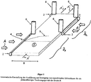
- FIG. 2 visualized a preferred embodiment of the invention, in which a pad 1 is designed as a conveyor belt, which makes in the direction of the illustrated arrows 1 'a promotion of here not further visualized to be dried Good.
- a pad 1 is designed as a conveyor belt, which makes in the direction of the illustrated arrows 1 'a promotion of here not further visualized to be dried Good.
- two regions B1 and B2 are provided behind one another in the conveying direction, in which direction of flow A of the gaseous fluid used for drying, such as air, is reversed.
- the inflow profiles 2 are arranged on opposite sides of the conveyor belt or the base 1. The same applies to the blower for generating the fluid flow.
- the invention can also provide that more than two such named areas follow one another in the conveying direction.
- the illustration with reference to the reference numerals 4 and 5 visualizes peel bubble and turbulent region, the latter extending substantially over a large part, in particular more than 90%, in the preferred embodiment across the width B of the conveyor belt.
- the flow shape is formed conversely to that in the region B1, so that viewed in the conveying direction in the middle, a uniform turbulent profile results, resulting in a uniform drying of subsidized Good.
- flow-conducting elements 6 can be arranged in the region between the regions B1 and B2 in order to better isolate the opposing flows from each other in terms of flow.
- the profile shape which in turn here in the Anströmprofilen 2 is shown in each case as a semicircular symbolized to make variable.
- the profile shape which in turn here in the Anströmprofilen 2 is shown in each case as a semicircular symbolized to make variable.
Landscapes
- Engineering & Computer Science (AREA)
- Mechanical Engineering (AREA)
- General Engineering & Computer Science (AREA)
- Life Sciences & Earth Sciences (AREA)
- Microbiology (AREA)
- Drying Of Solid Materials (AREA)
Description
- Die Erfindung betrifft ein Verfahren zur Konvektionstrocknung von Gütern, bei dem ein zu trocknendes Gut auf einer Unterlage angeordnet wird und einer Strömung eines zur Trocknung vorgesehenen gasförmigen Fluids ausgesetzt wird.
Die Erfindung betrifft weiterhin auch eine Trocknungsvorrichtung zur konvektiven Trocknung von Gütern umfassend eine Unterlage, insbesondere eine aus wenigstens einem Förderband ausgebildete Unterlage, auf der ein zu trocknendes Gut positionierbar ist und Mittel, insbesondere wenigstens ein Gebläse, zur Erzeugung einer Strömung eines zur Trocknung vorgesehenen gasförmigen Fluids. Ein derartiges Verfahren und eine derartige Vorrichtung sind aus derDE102007020837 bekannt. Verfahren und Vorrichtungen der eingangs genannten Art sind im Stand der Technik bekannt und werden eingesetzt, um feuchte Güter zu trocknen. Dabei ist es ein typisches Verfahren, die Strömung des zur Trocknung vorgesehenen gasförmigen Fluids parallel zur Flächennormale der Unterlage auszurichten, auf welcher das zu trocknende Gut angeordnet ist. Es wird so eine sogenannte Prallströmung erzeugt, die am Ort des unmittelbaren Auftreffens der Strömung auf das zu trocknende Gut, beziehungsweise auf die Unterlage, eine sehr schnelle konvektive Trocknung aufgrund eines hohen lokalen Stoffaustauschgrades erzielt, hier jedoch nachteiligerweise die Trocknungsgeschwindigkeit, beziehungsweise der Stoffaustauschgrad, mit zunehmendem Abstand vom Auftreffort der Strömung schnell abnimmt. Großflächige Güter werden daher mit einem solchen Verfahren oder einer solchen Vorrichtung nur sehr ungleichmäßig getrocknet. - Darüber hinaus weisen Trocknungsvorrichtungen dieser beschriebenen Art einen hohen Strömungswiderstand auf, so dass auch ein hoher Energiebedarf zum Erzeugen der Strömung benötigt wird.
Aufgabe der Erfindung ist es demnach, ein Verfahren zur Konvektionstrocknung und eine Trocknungsvorrichtung zum konvektiven Trocknen von Gütern bereitzustellen, mit welchen die Trocknungsgeschwindigkeit beziehungsweise der Stoffaustauschgrad großflächig verbessert werden kann, insbesondere bei geringerem Energieeinsatz gegenüber dem Stand der Technik. - Erfindungsgemäß wird dies mit einem Verfahren gemäß Anspruch 1 erzielt. Ein Anströmprofil ist hierbei zum Beispiel ein separat zur Unterlage vorgesehenes Element, oder eine Vorrichtung aus wenigstens einem Element, das/die entlang der Unterlage, insbesondere entlang einer Kante der Unterlage sich insbesondere senkrecht zumindest aber quer zur Strömungsrichtung erstreckt und das anströmende Fluid zumindest zu einem Teil über die Unterlage hinwegleitet. Ein Anströmprofil kann in anderer Ausführung jedoch auch einteilig mit der Unterlage sein, also z.B. durch eine seitliche Kante der Unterlage gebildet sein.
Eine Trocknungsvorrichtung der erfindungsgemäßen Art und insbesondere zur Durchführung des eingangs genannten Verfahrens ist insoweit, bezogen auf die eingangs genannten, gattungsbildenden Merkmale, weitergebildet, dass sie die Merkmale des Anspruchs 10 enthält. Dem erfindungsgemäßen Verfahren sowie der erfindungsgemäßen Trocknungsvonichtung liegt im Kem zugrunde, dass durch die beschriebene Art der Strömungsführung über der Unterlage bzw. über die Unterlage hinweg, auf welcher ein Gut zur Trocknung positionierbar ist, zunächst in Strömungsrichtung eine Ablöseblase gebildet wird, worunter ein Bereich der Strömung verstanden wird, in welchem sich diese Strömung von der Unterlage ablöst und einen Bereich minimalen Stoffaustauschgrades bildet, wohingegen sich nach der Ablöseblase die Strömung des zur Trocknung verwendeten Fluids erneut an die Unterlage anlegt und in diesem angelegten Bereich turbulent ausgebildet ist.
Eine Ablöseblase wird hier insoweit als transitionale Ablöseblase bezeichnet, als dass vor beziehungsweise in der Ablöseblase die Strömung laminar ausgebildet ist und nach der Ablöseblase die Strömung turbulent ausgebildet ist, demnach hier also ein Strömungsübergang von laminar nach turbulent vorliegt.
Untersuchungen haben gezeigt, dass durch die geometrische Ausformung des Anströmprofils, insbesondere der Formgebung des unmittelbar der Anströmung ausgesetzten Bereiches des Anströmprofils der Ort und die Länge der Ablöseblase beeinflussbar sind. Es kann so durch eine gezielte geometrische Formgebung des Anströmprofils, insbesondere durch ein in seiner geometrischen Form variabel verstellbares Anströmprofil, die Lage der Ablöseblase und somit auch die Lage des in Strömungsrichtung darauffolgenden turbulenten Strömungsbereiches beeinflusst werden. So kann es erzielt werden, den turbulenten Bereich in Strömungsrichtung besonders lang auszubilden.
Beispielsweise besteht so die Möglichkeit, eine, bezogen auf die in Strömungsrichtung liegende Länge der Unterlage, vergleichsweise kurze Ablöseblase von insbesondere weniger als 10 % der Länge einzustellen, so dass so in dem verbleibenden Längenbereich in Strömungsrichtung dieser Unterlage eine turbulente Strömung vorliegt. Es ergibt sich demnach ersichtlich im Vergleich zu Stand der Technik ein sehr großer turbulenter Strömungsbereich mit hohen Stoffaustauschgraden und somit verringerter Trocknungszeit. - Darüberhinaus wird bei der hier vorliegenden Strömungsrichtung und der Strömungsführung durch das Anströmprofil, durch welches das Fluid über die Unterlage hinweggeführt wird, ein deutlich geringerer Strömungswiderstand erzielt, als dies bei der üblichen Prallströmung im Stand der Technik der Fall ist. Hieraus resultiert auch unmittelbar ein geringerer Energieverbrauch bei der Durchführung des erfindungsgemäßen Verfahrens beziehungsweise beim dem Einsatz der erfindungsgemäßen Trocknungsvorrichtung.
- Unter einem Überströmen der Unterlage durch das Fluid wird hier weiterhin in Abgrenzung zur Prallströmung bevorzugt verstanden, dass das Fluid die Unterlage ausgehend von einer Kante der Unterlage bzw. ausgehend von dem Anströmprofil über die Unterlage hinweg zu einer gegenüberliegenden Kante strömt.
- Dies kann z.B. dadurch erfolgen, dass ein die Strömung erzeugendes Gebläse seitlich neben der Unterlage positioniert wird, insbesondere also im Gegensatz zur Prallströmung nicht über der Unterlage und das Fluid somit aus einer seitlichen Richtung in die Richtung der Unterlage geblasen wird.
- Da ein Fluidstrom immer einen Öffnungswinkel aufweist können die nachfolgenden Winkelangaben jeweils eine mittlere Strömungsrichtung im Öffnungswinkel beschreiben.
- Hier kann es vorgesehen sein, dass die Anströmrichtung des zur Trocknung vorgesehenen gasförmigen Fluids, wie beispielsweise Luft, in einem Winkelbereich von 35 Grad bis 145 Grad, bevorzugt 45 Grad bis 135 Grad, weiter bevorzugt von 60 Grad bis 120 Grad, weiter bevorzugt von 80 Grad bis 100 Grad zur Flächennormalen der Unterlage oder weiter bevorzugt zumindest im Wesentlichen senkrecht zur Flächennormalen der Unterlage gewählt wird.
- Im Gegensatz zur Prallströmung wird durch ein Anströmen des Anströmprofils durch das Fluid in einem Winkelbereich von 45 Grad bis 135 Grad, bevorzugt von 90 Grad zur Flächennormalen der Unterlage erreicht, dass bei einer (gedanklichen) Aufspaltung der Strömung in Komponenten senkrecht und parallel zur Flächennormalen die zur Flächennormalen der Unterlage senkrechte Komponente größer ist als die parallele Komponente.
- Das Anströmprofil kann hier im Wesentlichen als ein längserstrecktes Profil ausgebildet sein, dessen Längserstreckungsrichtung senkrecht zur Flächennormale der Unterlage ausgebildet ist, insbesondere wobei die Oberkante des Anströmprofils, zumindest im Wesentlichen, bevorzugt genau mit der Oberfläche der Unterlage in horizontaler Richtung, bevorzugt in Strömungsrichtung fluchtet. Hierdurch wird im Wesentlichen sichergestellt, dass das strömende Fluid nach Überschreiten der Oberkante des Anströmprofils sicher über die Unterlage hinweggeführt wird.
- Die Anströmung, die gemäß einleitender Erklärung in einem bevorzugtem Winkelbereich von 45 bis 135 Grad zur Flächennormalen und bevorzugt senkrecht zu dieser erfolgt kann um die Flächennormale der Unterlage herum grundsätzlich beliebig ausgerichtet sein, kann jedoch bevorzugt in einem Winkelbereich von 45 bis 135 Grad zur Längserstreckungsrichtung des Anströmprofils und bevorzugt zumindest im Wesentlichen senkrecht zu dieser Längserstreckungsrichtung orientiert sein. Somit kann die Anströmung grundsätzlich in einem Raumwinkelbereich gewählt werden, bevorzugt dessen Scheitelpunkt in der Ebene der Unterlage liegt und weiter bevorzugt dessen Mittenachse in der Ebene der Unterlage liegt.
- Eine vorteilhafte Ausbildung des erfindungsgemäßen Verfahrens beziehungsweise der Vorrichtung kann es vorsehen, dass die Unterlage durch ein Förderband gebildet wird, welches ein zu trocknendes Gut senkrecht zur Flächennormalen des Förderbandes und durch die Fluidströmung hindurch, insbesobndere quer zur Anströmrichtung und bevorzugt senkrecht zur Anströmungsrichtung des Fluids transportiert.
- Es kann so ein kontinuierlicher Trocknungsvorgang von mit dem Förderband geförderten Gütern erzielt werden, insbesondere wobei im Vergleich zum Stand der Technik die Verweildauern der Güter auf einem Förderband aufgrund der höheren erzielbaren Stoffaustauschgrade beziehungsweise kürzeren Trocknungszeiten verringert werden können. Es können demnach beispielsweise Förderbänder schneller laufen oder kürzer ausgebildet werden, als dies gegebenenfalls im Stand der Technik der Fall ist.
- Wie es bereits eingangs erwähnt wurde, ist es ein wesentlicher Vorteil der Erfindung, dass die zu trocknenden Güter in Strömungsrichtung nach einer Ablöseblase im turbulenten Bereich der Strömung auf der Unterlage beziehungsweise bevorzugt einem Förderband positioniert werden, um eine schnellere Trocknung im Vergleich zum Stand der Technik zu erzielen.
- Um dies weiter zu optimieren, kann es beispielsweise in einer Weiterbildung vorgesehen sein, dass der Ort der Ablöseblase und/oder deren Länge über der Unterlage messtechnisch erfasst wird und auf eine Sollposition relativ zur Unterlage oder relativ zu einem zu trocknenden Gut und/oder auch eine Solllänge eingestellt wird, insbesondere wofür zusätzlich die Position eines Gutes relativ zur Unterlage messtechnisch erfasst wird.
- Eine alternative Ausgestaltung kann es auch vorsehen, den Ort des Gutes auf der Unterlage messtechnisch zu erfassen und das Gut auf eine Sollposition relativ zur Unterlage oder relativ zur Ablöseblase einzustellen, um so sicherzustellen, dass das Gut im turbulenten Bereich nach der Ablöseblase, nicht jedoch bereits in der Ablöseblase, auf der Unterlage positioniert ist. Hierfür kann insbesondere auch die Position und/oder Länge der Ablöseblase relativ zur Unterlage oder relativ zum Gut messtechnisch erfasst werden, insbesondere mit einem Positionssensor optischer Art oder akustischer Art, z.B. basierend auf dem Ultraschall-Echo-Prinzip.
- Bei beiden alternativen Ausführungen kann es vorgesehen sein, dass der Ort der Ablöseblase und/oder deren Länge zum Beispiel ermittelt wird mittels wenigstens eines Strömungsmessers, wie beispielsweise eines Anemometers, insbesondere eines Hitzdraht-Anemometers oder eines Drucksensors, wobei allgemein ein solcher Strömungsmesser über der Unterlage in der Strömung angeordnet ist.
- Es kann hierbei vorgesehen sein, mit wenigstens einem solchen Strömungsmesser den Ort minimaler Strömungsgeschwindigkeit oder minimalen lokalen Druckes des zur Trocknung verwendeten Fluids zu bestimmen und hieraus den Schluss zu ziehen, dass der wenigstens eine Strömungsmesser im Wesentlichen im Zentrum der Ablöseblase oder mehrere Strömungsmesser um das Zentrum der Ablöseblase herum positioniert ist. Es kann so aus der Position des wenigstens einen Strömungsmessers die Position und/oder die Länge der Ablöseblase ermittelt werden, insbesondere um anhand dieser Position und/oder der Länge, wie eingangs beschrieben, das Verfahren beziehungsweise die Vorrichtung zu optimieren.
- Hierfür kann es beispielsweise weiterhin vorgesehen sein, dass der wenigstens eine Strömungsmesser entlang der Unterlage in Strömungsrichtung verschieblich ist, um so mit einem Antrieb die Position des wenigstens einen Strömungsmessers auf den Ort minimaler Strömungsgeschwindigkeit einzustellen und diese Position beziehungsweise deren Abweichung von einer Sollposition als Regelkriterium zur Nachregelung der Position und/oder der Länge der Ablöseblase zu nutzen.
- Eine alternative Ausführung kann es auch vorsehen, den Ort einer Ablöseblase und/oder deren Länge mittels einer optischen Erfassung wenigstens eines die Strömung visualisierenden Objektes vorzunehmen. Ein solches Objekt kann zum Beispiel durch Rauchpartikel gebildet werden, die mit der Strömung mitgeführt werden und eine Rauchfahne bilden und zum Beispiel optisch mittels einer Kamera erfasst werden.
- Ebenso kann ein in der Strömung liegendes Band die Strömungsform visualisieren und mittels einer Kamera erfasst werden, so dass in beiden Ausführungen die Möglichkeit besteht, mittels einer Bildauswertung anhand der visualisierten Strömungsform den Ort der Ablöseblase und/oder deren Länge festzustellen und gegebenenfalls den Ort und/oder die Länge der Ablöseblase oder die relative Lage eines Gutes zur Ablöseblase in Abhängigkeit eines solchen festgestellten Ortes zu verändern.
- Bei einer wiederrum anderen Ausführung kann es auch vorgesehen sein, thermografisch eine durch die Strömung bewirkte Auskühlung wenigstens eines der Strömung ausgesetzten, zum Beispiel geheizten Objektes zu erfassen.
- Für die thermografische Erfassung können beispielsweise übliche Wärmebildkameras zum Einsatz kommen, insbesondere mit denen Infrarotstrahlung im unsichtbaren Bereich erfasst wird.
- Ein der Strömung ausgesetztes Objekt kann in einem einfachen Fall ein Draht sein, der in Strömungsrichtung über der Unterlage, insbesondere parallel zur Unterlage angeordnet ist und der bestromt wird, um entlang seiner Erstreckungsrichtung in Strömungsrichtung erwärmt zu werden. Durch die Anordnung eines solchen Drahtes innerhalb der Strömung ergeben sich mehr oder weniger stark ausgekühlte Bereiche dieses Drahtes, je nach konkreter Ausbildung der Strömung an der jeweiligen Drahtposition.
- So kann am Ort der Ablöseblase, in welchem eine geringere Strömungsgeschwindigkeit vorherrscht, der Draht eine höhere Temperatur annehmen als im Bereich der turbulenten Strömung, so dass mittels einer thermografischen Erfassung eines solchen Drahtes sehr gut sowohl die örtliche Lage als auch die Länge der Ablöseblase bestimmt werden, insbesondere anhand des Ortes und/oder der Länge des wärmsten Bereiches eines solchen Drahtes. Hier ist es weiterhin vorteilhaft, wenn ein über der Unterlage, insbesondere parallel zu dieser gespannter erwärmter Draht in seinem Abstand zur Unterlage einstellbar ist.
- Um eine Optimierung des Verfahrens beziehungsweise der erfindungsgemäßen Vorrichtung vorzunehmen, kann es vorgesehen sein, den Ort und/oder die Länge der Ablöseblase, insbesondere in Abhängigkeit der vorherigen messtechnischen Erfassung auf gewünschte Sollwerte einzustellen. Hierfür kann ein Regelkreis zum Einsatz kommen mit wenigstens einem durch den Regelkreis angesteuerten Aktor, mit dem Einfluß genommen werden kann auf Ort und/oder Länge der Ablöseblase. Der wenigstens eine Aktor kann z.B. Ort und/oder Form des Anströmprofils und/oder Strömungsgeschwindigkeit oder Strömungsrichtung des Fluids ändern.
- Beispielsweise also kann die Beeinflussung von Ort und/oder Länge der Ablöseblase dadurch erfolgen, dass die Strömungsgeschwindigkeit des zur Trocknung verwendeten Fluids geändert wird. Weitere Möglichkeiten können darin bestehen, Änderung der Form des angeströmten Bereichs des Anströmprofils vorzunehmen. Hierfür kann beispielsweise ein Anströmprofil an der Vorrichtung vorgesehen sein, welches einen von der Kreisform abweichenden Querschnitt senkrecht zu seiner Erstreckungsrichtung hat, so dass die Erfindung beispielsweise vorsehen kann, das Anströmprofil um seine Längserstreckungsrichtung, insbesondere mit einem vorgenannten Aktor zu rotieren und so je nach Rotationswinkel unterschiedliche Bereiche des Anströmprofils durch die Strömung konkret anströmen zu lassen. Beispielsweise kann es vorgesehen sein, dass Anströmprofil im Querschnitt elliptisch auszubilden und das Anströmprofil um seine Längserstreckungsrichtung zu rotieren, um Lage und/oder Länge der Ablöseblase zu verändern.
- Eine andere Möglichkeit ist darin gegeben, die Höhe der Oberkante des Anströmprofils über der Oberfläche der Unterlage zu verändern. Auch besteht die Möglichkeit die Höhe des Anströmprofils insgesamt senkrecht zur Anströmungsrichtung variabel zu gestalten und durch eine Änderung der Höhe Lage und/oder Länge der Ablöseblase einzustellen. Auch mittels einer Lageänderung des Anströmprofils relativ zur Unterlage beziehungsweise zum Gut kann eine entsprechende Veränderung von Ort beziehungsweise Länge der Ablöseblase vorgenommen werden.
- Eine erfindungsgemäße Vorrichtung kann demnach eingerichtet sein, um die Form eines von der Strömung angeströmten Bereichs des Anströmprofils zu ändern oder aber die örtliche Position eine Anströmprofils relativ zur Unterlage und/oder zu einem darauf positionierten Gut zu verstellen, insbesondere in Abhängigkeit von zuvor messtechnisch erfassten Werten des Ortes der Ablöseblase, der Länge der Ablöseblase oder des Ortes des zu trocknenden Gutes auf der Unterlage beziehungsweise relativ zur Ablöseblase. Um die Relativposition vom Gut zur Ablöseblase bzw. zum Anströmprofil zu ändern kann ebenso wenigstens ein Aktor vorgesehen sein, mit dem die Position des Gutes auf der Unterlage, z.B. einem Förderband geändert werden kann. Z.B. können verschiebliche Schieberelement über der Unterlage vorgesehen sein, die angesteuert werden, das Gut, z.B. beim Vorbeifördern durch ein Förderband zu bewegen.
- Besonders bei einer Ausführungsform, die den Einsatz eines Förderbandes vorsieht, um zu trocknende Güter durch eine Strömung eines zur Trocknung vorgesehenen Fluids zu verwenden, kann eine Weiterbildung zum Zwecke der Vergleichmäßigung der Trocknung vorsehen, dass in der Förderrichtung einer aus wenigstens einem Förderband ausgebildeten Unterlage abwechselnd aufeinander Bereiche, insbesondere wenigstens zwei Bereiche folgen, in denen das gasförmige Fluid das wenigstens eine Förderband in entgegengesetzten Richtungen überströmt, insbesondere in denen die Anströmprofile auf einander gegenüberliegenden Seiten des Förderbandes angeordnet sind. Es kann hierbei vorgesehen sein, dass ein einziges Förderband durch die mehreren Bereiche die Güter hindurchbefördert oder aber auch, dass jeder Bereich sein eigenes Förderband aufweist und zwischen den Bereichen eine Übergabe der zu trocknenden Güter von einem Förderband zum nächsten erfolgt.
- Insbesondere die letztgenannte Ausführung hat den Vorteil, dass erfindungsgemäße Trocknungsvorrichtungen, die jeweils ihr eigenes Förderband zum Transport von Gütern aufweisen, mehrfach hintereinander, jedoch mit jeweils entgegengesetzten Strömungsrichtungen, also um 180 Grad gegeneinander verdreht, positioniert werden können, um diesen erfindungsgemäßen Vorteil zu realisieren.
- Hierbei kann eine Weiterbildung vorsehen, dass zwischen zwei aufeinanderfolgenden Bereichen strömungsformende Elemente, insbesondere über dem Förderband angeordnet sind. Diese könnten z.B. als Leitbleche ausgebildet sein, die senkrecht zum Förderband orientiert sind bzw. parallel zu dessen Flächennormalen. Es kann vorgesehen sein, dass solche Leitbleche positionsvariabel sind, z.B. um eine Achse parallel zur Flächennormalen der Unterlage rotiert werden können.
- Die theoretischen Grundlagen sowie ein Ausführungsbeispiel der Erfindung werden anhand der nachfolgenden Figuren erläutert.
- Die
Figuren 1 zeigen in drei verschiedenen Darstellungen die sich ausbildende Strömung über einer Unterlage 1, auf welcher jeweils ein hier nicht dargestelltes Gut angeordnet werden kann. Bezogen auf die hier dargestellteFigur 1 kann eine Förderung des Gutes senkrecht zur Papierebene vorgesehen sein. DieFigur 1 zeigt eine Anströmung A der Unterlage 1 und eines darauf positionierten Gutes senkrecht zur Flächennormalen der Unterlage 1, wobei in derFigur 1 a kein Anströmprofil vorhanden ist. Gemäß den physikalischen Gesetzen ergibt sich ein signifikant ausgebildeter laminar Strömungsbereich und ein sich daran anschließender turbulenter Strömungsbereich. Ersichtlich ist hier der Nachteil erkennbar, dass der laminare Strömungsbereich, bezogen auf die Ortskoordinate der Unterlage 1, einen sehr großen Anteil einnimmt und in diesem laminaren Strömungsbereich die Trocknungsraten gering sind. - Dem gegenüber visualisiert die
Figur 1b eine erfindungsgemäße Durchführung des Verfahrens, bei welchem in Strömungsrichtung vor einer Unterlage 1 ein Anströmprofil 2 angeordnet ist, welches hier hinsichtlich seiner Formgestaltung im Querschnitt in Strömungsrichtung im Wesentlichen halbkreisförmig ausgebildet ist. Die visualisierte Darstellung der Strömung 3 zeigt eine in Strömungsrichtung nahe des Anströmprofils 2 liegende kurze Ablöseblase 3a und einen dahinter liegenden, vergleichsweise hinsichtlich der Ortskoordinate x länger ausgebildeten turbulenten Strömungsbereich 3b. Innerhalb der Ablöseblase 3a existiert ein Bereich 3c mit minimaler oder sogar umgekehrter Strömung bzw. einer Rezirkulation, der messtechnisch, gemäß den vorherigen Ausführungen im allgemeinen Beschreibungsteil, erfasst werden kann. - Die
Figur 1b zeigt in der oberen Darstellung ein ausgeprägtes Minimum 4 des konvektiven Stoffübergangskoeffizienten, welches die Existenz der Ablöseblase belegt. In Strömungsrichtung nach der Ablöseblase hingegen folgt ein Bereich turbulenter Strömung mit signifikant erhöhtem konvektivem Stoffübergangskoeffizienten, so dass es erfindungsgemäß vorteilhaft ist, im Bereich 3b der turbulenten Strömung nach der Ablöseblase zu trocknende Güter zu positionieren und diesen Bereich möglichst lang, somit die Ablöseblase möglichst kurz zu gestalten. - Die
Figur 1b visualisiert hier im Wesentlichen weiterhin, dass die Oberkante des Anströmprofils 2 im Wesentlichen mit der Oberfläche der Unterlage 1 fluchtend ausgebildet ist. Das Anströmprofil kann eine Höhe größer als die Dicke der Unterlage haben. - Im Sinne der Strömungslehre beziehungsweise physikalischer Gesetzmäßigkeiten bildet eine Unterlage mit einem solchen in Strömungsrichtung vorangestellten Anströmprofil eine sogenannte "dicke Platte" im Gegensatz zur "dünnen Platte" der
Figur 1 a. - In der
Figur 1b beziehungsweise allgemein bezogen auf die Ausführungsformen der Erfindung kann es vorgesehen sein, dass ein Anströmprofil 2 als separates Bauteil zur Unterlage ausgebildet ist, das Anströmprofil 2 kann jedoch in einer alternativen Ausgestaltung auch unmittelbar an die Unterlage 1 angeformt sein beziehungsweise mit dieser einstückig ausgebildet sein. - Die
Figur 1c zeigt als weitere Ausgestaltung eine andere Formgebung des Anströmprofils 2, welches hier beispielsweise einteilig mit der Unterlage ausgebildet sein kann. Hier ergibt sich gegenüber derFigur 1b eine deutlich längere Ablöseblase und ein kürzerer turbulenter Bereich 3b in der Erstreckungsrichtung der Strömung. Der Vergleich zwischen denFiguren 1b und 1c visualisiert hier im Wesentlichen, dass durch Änderung der geometrischen Profilform des Anströmprofils sowohl die örtliche Lage als auch die Länge der Ablöseblase beeinflussbar ist, so dass es erfindungsgemäß, wie im allgemeinen Teil beschrieben, eine Ausführung der Erfindung vorsehen kann, durch Änderung der geometrischen Form des Anströmprofils bzw. zumindest von dessen angeströmten Bereich den Ort und/oder die Länge der Ablöseblase beeinflussen zu können. Eine solche Beeinflussung kann insbesondere in Abhängigkeit wenigstens eines Messwertes erfolgen, welche den gemessenen Ort und/oder die Länge der Ablöseblase repräsentiert. -
Figur 2 visualisiert ein bevorzugtes Ausführungsbeispiel der Erfindung, bei welcher eine Unterlage 1 als Förderband ausgebildet ist, welche in Richtung der dargestellten Pfeile 1' eine Förderung von hier nicht weiter visualisierten zu trocknenden Gut vornimmt. Es sind bei dieser hier betrachteten Ausführungsform in Förderrichtung hintereinanderliegend zwei Bereiche B1 und B2 vorgesehen, bei denen die Strömungsrichtung A des zur Trocknung verwendeten gasförmigen Fluids, wie beispielsweise Luft, umgekehrt ist. - Demnach sind weiterhin auch erfindungsgemäß die Anströmprofile 2 auf gegenüberliegenden Seiten des Förderbandes beziehungsweise der Unterlage 1 angeordnet. Gleiches gilt für die Gebläse zur Erzeugung des Fluidstromes.
- Statt der hier lediglich visualisierten zwei Bereiche, kann die Erfindung auch vorsehen, dass mehr als zwei solcher genannter Bereiche in Förderrichtung aufeinander folgen. Die Darstellung unter Bezugnahme auf die Bezugszeichen 4 und 5 visualisiert Ablöseblase und turbulenten Bereich, wobei sich letzterer maßgeblich über einen Großteil, insbesondere mehr als 90 %, in der bevorzugten Ausführung über die Breite B des Förderbandes erstreckt. Im Bereich B2 ist die Strömungsform umgekehrt ausgebildet zu derjenigen im Bereich B1, so dass sich im Mittel in Förderrichtung betrachtet, ein vergleichmäßigtes turbulentes Profil ergibt, was zu einer vergleichmäßigten Trocknung von geförderten Gut führt.
- Weiterhin zeigt die
Figur 2 , dass im Bereich zwischen den Bereichen B1 und B2 strömungsleitende Elemente 6 angeordnet werden können, um die einander entgegengesetzten Strömungen strömungstechnisch besser voneinander zu isolieren. - Auch hier kann es vorgesehen sein, die Profilform, die bei den Anströmprofilen 2 hier wiederrum jeweils als halbkreisförmig symbolisiert dargestellt ist, variabel gestalten zu können. Beispielsweise kann es wie im eingangs genannten Beschreibungsteil beschrieben, vorgesehen sein, ein Anströmprofil im Querschnitt senkrecht zur Förderrichtung beziehungsweise im Querschnitt in Anströmrichtung elliptisch auszubilden und durch eine Rotation senkrecht zur Anströmrichtung beziehungsweise um eine Achse in Förderrichtung je nach Winkelstellung verschiedene angeströmte Formen bereitzustellen und so die Lage der Ablöseblase zu verändern, ebenso wie deren Länge.
- Hier steht es insbesondere zu erwarten, mit Verweis auf die
Figuren 1b und 1c , dass bei einer Ausrichtung der langen Halbachse der Querschnittsellipse in Strömungsrichtung und somit einer der Anströmung ausgesetzten starken Krümmung des Anströmprofils eine kürzere Ablöseblase erzielt wird im Vergleich zu einer Ausrichtung des Ellipsenquerschnittes, bei welcher die kurze Halbachse der Ellipse in Anströmrichtung liegt. So kann bei einer beispielsweise elliptischen Querschnittsformung des Anströmprofils durch eine Drehung des Anströmprofils um lediglich 90 Grad Länge und Ort der Ablöseblase relativ zur Unterlage 1 beziehungsweise zu einem zu fördernden Gut eingestellt werden.
Claims (11)
- Verfahren zur Konvektionstrocknung von Gütern, bei dem ein zu trocknendes Gut auf einer Unterlage (1) angeordnet wird und einer Strömung eines zur Trocknung vorgesehenen gasförmigen Fluids ausgesetzt wird, dadurch gekennzeichnet dassa. mit dem Fluid ein in Strömungsrichtung (A) vor dem Gut angeordnetes Anströmprofil (2), insbesondere vor der Unterlage (1) angeordnetes Anströmprofil (2), insbesondere seitlich neben der Unterlage (1) angeordnetes Anströmprofil (2), angeströmt und die Unterlage (1) überströmt wird, insbesondere wobei die Oberkante des Anströmprofils (2) zumindest im Wesentlichen mit der Oberfläche der Unterlage (1) in Strömungsrichtung (A) fluchtet, undb. das zu trocknende Gut in einem Bereich der Unterlage (1) positioniert wird, der in Strömungsrichtung nach einer über der Unterlage (1) gebildeten, insbesondere transitionalen Ablöseblase (3b) des Fluids liegt.
- Verfahren nach Anspruch 1, dadurch gekennzeichnet, dass die Anströmungsrichtung (A) des Fluids in einem Winkelbereich von 45 bis 135 Grad zur Flächennormalen, insbesondere senkrecht zur Flächennormalen der Unterlage (1) gewählt wird.
- Verfahren nach einem der vorherigen Ansprüche, dadurch gekennzeichnet, dass die Unterlage (1) durch ein Förderband gebildet wird, welches ein zu trocknendes Gut senkrecht zur Flächennormalen des Förderbandes und durch die Fluidströmung hindurch, insbesondere quer zur Anströmrichtung und bevorzugt senkrecht zur Anströmungsrichtung des Fluids transportiert.
- Verfahren nach einem der vorherigen Ansprüche, dadurch gekennzeichnet, dass der Ort der Ablöseblase (3b) und/oder die Länge der Ablöseblase (3b) über der Unterlage (1) messtechnisch erfasst wird und auf eine Sollposition relativ zur Unterlage (1) oder relativ zu einem zu trocknenden Gut eingestellt wird, insbesondere wofür zusätzlich die Position eines Gutes relativ zur Unterlage (1) messtechnisch erfasst wird.
- Verfahren nach einem der vorherigen Ansprüche, dadurch gekennzeichnet, dass der Ort des Gutes auf der Unterlage (1) messtechnisch erfasst wird und auf eine Sollposition relativ zur Unterlage (1) oder relativ zur Ablöseblase (3b) eingestellt wird, insbesondere wofür die Position der Ablöseblase (3b) relativ zur Unterlage (1) oder relativ zum Gut messtechnisch erfasst wird.
- Verfahren nach Anspruch 4 oder 5, dadurch gekennzeichnet, dass der Ort der Ablöseblase (3b) ermittelt wird mittelsa. wenigstens eines Strömungsmessers, insbesondere eines Anemometers, der über der Unterlage (1) in der Strömung angeordnet istb. einer optischen Erfassung wenigstens eines die Strömung visualisierenden Objektes, insbesondere Rauchpartikel oder ein in der Strömung liegendes Bandc. einer thermografischen Erfassung einer durch die Strömung bewirkten Auskühlung wenigstens eines der Strömung ausgesetzten Objektes
- Verfahren nach einem der vorherigen Ansprüche, dadurch gekennzeichnet, dass der Ort und/oder die Länge der Ablöseblase (3b) eingestellt wird durcha. Änderung der Strömungsgeschwindigkeit und/oderb. Änderung der Form des angeströmten Bereichs des Anströmprofil (2) und/oderc. Änderung der Höhe der Oberkante des Anströmprofils (2) über der Oberfläche des Unterlage und/oderd. Änderung der Höhe des Anströmprofils (2) senkrecht zur Anströmungsrichtung und/odere. Änderung des Abstandes des Anströmprofils (2) zur Unterlage oder zum Gut und/oderf. Änderung des Anströmwinkels des Fluids zur Flächennormalen der Unterlage (1).
- Verfahren nach einem der vorherigen Ansprüche, dadurch gekennzeichnet, dass in Förderrichtung einer aus wenigstens einem Förderband ausgebildeten Unterlage (1) abwechselnd aufeinander Bereiche (B1, B2), insbesondere wenigstens zwei Bereiche folgen, in denen das Fluid das wenigstens eine Förderband in entgegengesetzten Richtungen überströmt, insbesondere in denen die Anströmprofile (2) auf einander gegenüberliegenden Seiten des Förderbandes angeordnet sind.
- Verfahren nach Anspruch 8, dadurch gekennzeichnet, dass zwischen zwei aufeinanderfolgenden Bereichen (B1, B2) strömungsformende Elemente, insbesondere über dem Förderband angeordnet sind.
- Trocknungsvorrichtung zur konvektiven Trocknung von Gütern umfassend eine Unterlage (1), insbesondere eine aus wenigstens einem Förderband ausgebildete Unterlage (1), auf der ein zu trocknendes Gut positionierbar ist und Mittel, insbesondere wenigstens ein Gebläse, zur Erzeugung einer Strömung eines zur Trocknung vorgesehenen gasförmigen Fluids, dadurch gekennzeichnet, dass die Mittel zur Erzeugung einer Strömung ausgerichtet sind zur Erzeugung einer Strömung über die Unterlage (1) hinweg, wobei die Trocknungsvorrichtung wenigstens ein in Strömungsrichtung vor der Unterlage (1) angeordnetes Anströmprofil umfasst, wobei die erzeugte Strömung des Fluids auf das wenigstens eine in Strömungsrichtung vor der Unterlage (1), insbesondere seitlich neben der Unterlage (1) angeordnete Anströmprofil (2) so ausgerichtet ist, dass während der Benutzung der Trocknungsvorrichtung eine transitionale Ablöseblase (3b) erzeugt wird, wobei ein Bereich auf der Unterlage (1) gebildet wird, in welchem das zu trocknende Gut positionierbar ist und welches in einem in Strömungsrichtung (A) auf die Ablöseblase (3b) folgenden turbulenten Strömungsbereich (3c) des Fluids liegt.
- Trocknungsvorrichtung nach Anspruch 10, dadurch gekennzeichnet, dass das Anströmprofil (2) änderbar ist hinsichtlicha. der Form eines von der Strömung angeströmten Bereichs des Anströmprofils (2)b. seiner örtlichen Position relativ zur Unterlage und/oder einem darauf positionierten Gut
Applications Claiming Priority (2)
| Application Number | Priority Date | Filing Date | Title |
|---|---|---|---|
| DE102013016001.4A DE102013016001A1 (de) | 2013-09-26 | 2013-09-26 | Verfahren und Vorrichtung zur Konvektionstrocknung von Gütern |
| PCT/EP2014/002274 WO2015043706A1 (de) | 2013-09-26 | 2014-08-19 | Verfahren und vorrichtung zur konvektionstrocknung von gütern |
Publications (3)
| Publication Number | Publication Date |
|---|---|
| EP3049742A1 EP3049742A1 (de) | 2016-08-03 |
| EP3049742B1 true EP3049742B1 (de) | 2017-11-29 |
| EP3049742B8 EP3049742B8 (de) | 2018-04-18 |
Family
ID=51564616
Family Applications (1)
| Application Number | Title | Priority Date | Filing Date |
|---|---|---|---|
| EP14766659.8A Not-in-force EP3049742B8 (de) | 2013-09-26 | 2014-08-19 | Verfahren und vorrichtung zur konvektionstrocknung von gütern |
Country Status (3)
| Country | Link |
|---|---|
| EP (1) | EP3049742B8 (de) |
| DE (1) | DE102013016001A1 (de) |
| WO (1) | WO2015043706A1 (de) |
Families Citing this family (1)
| Publication number | Priority date | Publication date | Assignee | Title |
|---|---|---|---|---|
| CN109028878A (zh) * | 2018-05-31 | 2018-12-18 | 安龙县西城秀树农林有限责任公司 | 一种石斛智能烘干设备 |
Family Cites Families (2)
| Publication number | Priority date | Publication date | Assignee | Title |
|---|---|---|---|---|
| IT1210966B (it) * | 1982-12-24 | 1989-09-29 | Majo Renato M Di | Energia. metodo di lavorazione industrialedi sostanze organiche che consente di ottenere un avanzato stato di disidratazione delle sostanze stesse con basso impiego di |
| DE102007020837A1 (de) * | 2007-05-02 | 2008-11-06 | Hochschule Konstanz, Hochschule für Technik, Wirtschaft und Gestaltung | Verfahren und Vorrichtung zur Trocknung von Gut |
-
2013
- 2013-09-26 DE DE102013016001.4A patent/DE102013016001A1/de not_active Withdrawn
-
2014
- 2014-08-19 EP EP14766659.8A patent/EP3049742B8/de not_active Not-in-force
- 2014-08-19 WO PCT/EP2014/002274 patent/WO2015043706A1/de not_active Ceased
Also Published As
| Publication number | Publication date |
|---|---|
| WO2015043706A1 (de) | 2015-04-02 |
| DE102013016001A1 (de) | 2015-03-26 |
| EP3049742A1 (de) | 2016-08-03 |
| EP3049742B8 (de) | 2018-04-18 |
Similar Documents
| Publication | Publication Date | Title |
|---|---|---|
| DE69620185T2 (de) | Verfahren und vorrichtung zur beeinflussung der grenzschicht in einem kontinuierlichen medium | |
| DE112020000365B4 (de) | Verfahren zum Bestimmen einer Strömungsgeschwindigkeitsverteilung rauer Unterschicht | |
| EP2811268A1 (de) | Durchflussmesser | |
| DE202011110089U1 (de) | Vorrichtung zum Ausrichten eines nicht-kreisrunden oder mehreckigen Gegenstands | |
| DE112015004688B4 (de) | Anhaltende Übersättigungen für Kondensationswachstum von Teilchen | |
| DE212020000801U1 (de) | Gaseinlass-Struktur für Vorrichtungen zur schichtweisen Herstellung dreidimensionaler Objekte | |
| DE4007230A1 (de) | Vorrichtung zur aenderung der richtung einer luftstroemung | |
| WO2015043706A1 (de) | Verfahren und vorrichtung zur konvektionstrocknung von gütern | |
| DD149383A5 (de) | Verfahren und vorrichtung zum kontinuierlichen waermebehandeln von vereinzeltem,langgestrecktem metallischem gut | |
| DE112016005020T5 (de) | Verfahren zum Herstellen eines Einkristall-Siliziums und Einkristall-Silizium | |
| EP3468772B1 (de) | Basisstruktur, vorrichtung und verfahren zum transport von folie | |
| DE3637537A1 (de) | Vorrichtung zur bestimmung der durchflussrichtung | |
| DE102013107213A1 (de) | Verfahren und Anlage zur Steuerung der Temperierung eines Autoklaven-Fertigungsprozesses | |
| DE112017003940T5 (de) | Bolometerfluidstrom- und Temperatursensor | |
| DE102014000269B4 (de) | Verfahren und Vorrichtung zum Ermitteln der Planheit beim Behandeln eines bandförmigen Guts | |
| DE102019102595A1 (de) | Verfahren zum Abkühlen von bewegtem metallischen Material sowie Vorrichtung zur Durchführung eines solchen Verfahrens | |
| DE2640265C3 (de) | Vorrichtung zur Warnung vor der Gefahr einer Eisbildung in einer Atmosphäre | |
| EP4331805A2 (de) | Extrusionsvorrichtung und extrusionsverfahren | |
| DE102007020837A1 (de) | Verfahren und Vorrichtung zur Trocknung von Gut | |
| DE102011050372A1 (de) | Vorrichtung zum Strecken und/oder Ausrichten von Teigrohlingen, insbesondere von zur Brezelherstellung vorgeformten Teigsträngen | |
| DE1629026B1 (de) | Hängetrockner für beschichtete Materialbahnen | |
| DE1271524B (de) | Verfahren und Vorrichtung zum UEberziehen von Kernstuecken mit Schokolade | |
| DE2246798C3 (de) | Versuchsanlage zur Einzel- oder Mehrfachbeschichtung und Trocknung von Papier- oder Folienbahnen | |
| DE102017124721A1 (de) | Vorrichtung zum Führen zumindest einer Materialbahn | |
| EP2164625B1 (de) | Vorrichtung zum kontinuierlichen polymerisieren |
Legal Events
| Date | Code | Title | Description |
|---|---|---|---|
| PUAI | Public reference made under article 153(3) epc to a published international application that has entered the european phase |
Free format text: ORIGINAL CODE: 0009012 |
|
| 17P | Request for examination filed |
Effective date: 20160425 |
|
| AK | Designated contracting states |
Kind code of ref document: A1 Designated state(s): AL AT BE BG CH CY CZ DE DK EE ES FI FR GB GR HR HU IE IS IT LI LT LU LV MC MK MT NL NO PL PT RO RS SE SI SK SM TR |
|
| AX | Request for extension of the european patent |
Extension state: BA ME |
|
| RIN1 | Information on inventor provided before grant (corrected) |
Inventor name: AUS DER WIESCHE, STEFAN Inventor name: HELCIG, CHRISTIAN Inventor name: UHKOETTER, STEFAN |
|
| DAX | Request for extension of the european patent (deleted) | ||
| GRAP | Despatch of communication of intention to grant a patent |
Free format text: ORIGINAL CODE: EPIDOSNIGR1 |
|
| INTG | Intention to grant announced |
Effective date: 20170712 |
|
| RIN1 | Information on inventor provided before grant (corrected) |
Inventor name: UNKOETTER, STEFAN Inventor name: HELCIG, CHRISTIAN Inventor name: AUS DER WIESCHE, STEFAN |
|
| GRAS | Grant fee paid |
Free format text: ORIGINAL CODE: EPIDOSNIGR3 |
|
| GRAA | (expected) grant |
Free format text: ORIGINAL CODE: 0009210 |
|
| AK | Designated contracting states |
Kind code of ref document: B1 Designated state(s): AL AT BE BG CH CY CZ DE DK EE ES FI FR GB GR HR HU IE IS IT LI LT LU LV MC MK MT NL NO PL PT RO RS SE SI SK SM TR |
|
| REG | Reference to a national code |
Ref country code: CH Ref legal event code: EP |
|
| REG | Reference to a national code |
Ref country code: AT Ref legal event code: REF Ref document number: 950768 Country of ref document: AT Kind code of ref document: T Effective date: 20171215 |
|
| REG | Reference to a national code |
Ref country code: IE Ref legal event code: FG4D Free format text: LANGUAGE OF EP DOCUMENT: GERMAN |
|
| REG | Reference to a national code |
Ref country code: DE Ref legal event code: R096 Ref document number: 502014006422 Country of ref document: DE |
|
| REG | Reference to a national code |
Ref country code: NL Ref legal event code: MP Effective date: 20171129 |
|
| REG | Reference to a national code |
Ref country code: LT Ref legal event code: MG4D |
|
| RIN2 | Information on inventor provided after grant (corrected) |
Inventor name: AUS DER WIESCHE, STEFAN Inventor name: HELCIG, CHRISTIAN Inventor name: UHKOETTER, STEFAN |
|
| PG25 | Lapsed in a contracting state [announced via postgrant information from national office to epo] |
Ref country code: FI Free format text: LAPSE BECAUSE OF FAILURE TO SUBMIT A TRANSLATION OF THE DESCRIPTION OR TO PAY THE FEE WITHIN THE PRESCRIBED TIME-LIMIT Effective date: 20171129 Ref country code: SE Free format text: LAPSE BECAUSE OF FAILURE TO SUBMIT A TRANSLATION OF THE DESCRIPTION OR TO PAY THE FEE WITHIN THE PRESCRIBED TIME-LIMIT Effective date: 20171129 Ref country code: ES Free format text: LAPSE BECAUSE OF FAILURE TO SUBMIT A TRANSLATION OF THE DESCRIPTION OR TO PAY THE FEE WITHIN THE PRESCRIBED TIME-LIMIT Effective date: 20171129 Ref country code: NO Free format text: LAPSE BECAUSE OF FAILURE TO SUBMIT A TRANSLATION OF THE DESCRIPTION OR TO PAY THE FEE WITHIN THE PRESCRIBED TIME-LIMIT Effective date: 20180228 Ref country code: LT Free format text: LAPSE BECAUSE OF FAILURE TO SUBMIT A TRANSLATION OF THE DESCRIPTION OR TO PAY THE FEE WITHIN THE PRESCRIBED TIME-LIMIT Effective date: 20171129 |
|
| PG25 | Lapsed in a contracting state [announced via postgrant information from national office to epo] |
Ref country code: HR Free format text: LAPSE BECAUSE OF FAILURE TO SUBMIT A TRANSLATION OF THE DESCRIPTION OR TO PAY THE FEE WITHIN THE PRESCRIBED TIME-LIMIT Effective date: 20171129 Ref country code: GR Free format text: LAPSE BECAUSE OF FAILURE TO SUBMIT A TRANSLATION OF THE DESCRIPTION OR TO PAY THE FEE WITHIN THE PRESCRIBED TIME-LIMIT Effective date: 20180301 Ref country code: LV Free format text: LAPSE BECAUSE OF FAILURE TO SUBMIT A TRANSLATION OF THE DESCRIPTION OR TO PAY THE FEE WITHIN THE PRESCRIBED TIME-LIMIT Effective date: 20171129 Ref country code: RS Free format text: LAPSE BECAUSE OF FAILURE TO SUBMIT A TRANSLATION OF THE DESCRIPTION OR TO PAY THE FEE WITHIN THE PRESCRIBED TIME-LIMIT Effective date: 20171129 Ref country code: BG Free format text: LAPSE BECAUSE OF FAILURE TO SUBMIT A TRANSLATION OF THE DESCRIPTION OR TO PAY THE FEE WITHIN THE PRESCRIBED TIME-LIMIT Effective date: 20180228 |
|
| PG25 | Lapsed in a contracting state [announced via postgrant information from national office to epo] |
Ref country code: NL Free format text: LAPSE BECAUSE OF FAILURE TO SUBMIT A TRANSLATION OF THE DESCRIPTION OR TO PAY THE FEE WITHIN THE PRESCRIBED TIME-LIMIT Effective date: 20171129 |
|
| REG | Reference to a national code |
Ref country code: DE Ref legal event code: R083 Ref document number: 502014006422 Country of ref document: DE |
|
| PG25 | Lapsed in a contracting state [announced via postgrant information from national office to epo] |
Ref country code: EE Free format text: LAPSE BECAUSE OF FAILURE TO SUBMIT A TRANSLATION OF THE DESCRIPTION OR TO PAY THE FEE WITHIN THE PRESCRIBED TIME-LIMIT Effective date: 20171129 Ref country code: DK Free format text: LAPSE BECAUSE OF FAILURE TO SUBMIT A TRANSLATION OF THE DESCRIPTION OR TO PAY THE FEE WITHIN THE PRESCRIBED TIME-LIMIT Effective date: 20171129 Ref country code: SK Free format text: LAPSE BECAUSE OF FAILURE TO SUBMIT A TRANSLATION OF THE DESCRIPTION OR TO PAY THE FEE WITHIN THE PRESCRIBED TIME-LIMIT Effective date: 20171129 Ref country code: CZ Free format text: LAPSE BECAUSE OF FAILURE TO SUBMIT A TRANSLATION OF THE DESCRIPTION OR TO PAY THE FEE WITHIN THE PRESCRIBED TIME-LIMIT Effective date: 20171129 Ref country code: CY Free format text: LAPSE BECAUSE OF FAILURE TO SUBMIT A TRANSLATION OF THE DESCRIPTION OR TO PAY THE FEE WITHIN THE PRESCRIBED TIME-LIMIT Effective date: 20171129 |
|
| REG | Reference to a national code |
Ref country code: DE Ref legal event code: R097 Ref document number: 502014006422 Country of ref document: DE |
|
| PG25 | Lapsed in a contracting state [announced via postgrant information from national office to epo] |
Ref country code: PL Free format text: LAPSE BECAUSE OF FAILURE TO SUBMIT A TRANSLATION OF THE DESCRIPTION OR TO PAY THE FEE WITHIN THE PRESCRIBED TIME-LIMIT Effective date: 20171129 Ref country code: SM Free format text: LAPSE BECAUSE OF FAILURE TO SUBMIT A TRANSLATION OF THE DESCRIPTION OR TO PAY THE FEE WITHIN THE PRESCRIBED TIME-LIMIT Effective date: 20171129 Ref country code: IT Free format text: LAPSE BECAUSE OF FAILURE TO SUBMIT A TRANSLATION OF THE DESCRIPTION OR TO PAY THE FEE WITHIN THE PRESCRIBED TIME-LIMIT Effective date: 20171129 Ref country code: RO Free format text: LAPSE BECAUSE OF FAILURE TO SUBMIT A TRANSLATION OF THE DESCRIPTION OR TO PAY THE FEE WITHIN THE PRESCRIBED TIME-LIMIT Effective date: 20171129 |
|
| PG25 | Lapsed in a contracting state [announced via postgrant information from national office to epo] |
Ref country code: MT Free format text: LAPSE BECAUSE OF FAILURE TO SUBMIT A TRANSLATION OF THE DESCRIPTION OR TO PAY THE FEE WITHIN THE PRESCRIBED TIME-LIMIT Effective date: 20171129 |
|
| PLBE | No opposition filed within time limit |
Free format text: ORIGINAL CODE: 0009261 |
|
| STAA | Information on the status of an ep patent application or granted ep patent |
Free format text: STATUS: NO OPPOSITION FILED WITHIN TIME LIMIT |
|
| 26N | No opposition filed |
Effective date: 20180830 |
|
| PG25 | Lapsed in a contracting state [announced via postgrant information from national office to epo] |
Ref country code: SI Free format text: LAPSE BECAUSE OF FAILURE TO SUBMIT A TRANSLATION OF THE DESCRIPTION OR TO PAY THE FEE WITHIN THE PRESCRIBED TIME-LIMIT Effective date: 20171129 |
|
| PG25 | Lapsed in a contracting state [announced via postgrant information from national office to epo] |
Ref country code: MC Free format text: LAPSE BECAUSE OF FAILURE TO SUBMIT A TRANSLATION OF THE DESCRIPTION OR TO PAY THE FEE WITHIN THE PRESCRIBED TIME-LIMIT Effective date: 20171129 |
|
| REG | Reference to a national code |
Ref country code: CH Ref legal event code: PL |
|
| GBPC | Gb: european patent ceased through non-payment of renewal fee |
Effective date: 20180819 |
|
| PG25 | Lapsed in a contracting state [announced via postgrant information from national office to epo] |
Ref country code: LU Free format text: LAPSE BECAUSE OF NON-PAYMENT OF DUE FEES Effective date: 20180819 Ref country code: LI Free format text: LAPSE BECAUSE OF NON-PAYMENT OF DUE FEES Effective date: 20180831 Ref country code: CH Free format text: LAPSE BECAUSE OF NON-PAYMENT OF DUE FEES Effective date: 20180831 |
|
| REG | Reference to a national code |
Ref country code: BE Ref legal event code: MM Effective date: 20180831 |
|
| REG | Reference to a national code |
Ref country code: IE Ref legal event code: MM4A |
|
| PG25 | Lapsed in a contracting state [announced via postgrant information from national office to epo] |
Ref country code: IE Free format text: LAPSE BECAUSE OF NON-PAYMENT OF DUE FEES Effective date: 20180819 |
|
| PG25 | Lapsed in a contracting state [announced via postgrant information from national office to epo] |
Ref country code: BE Free format text: LAPSE BECAUSE OF NON-PAYMENT OF DUE FEES Effective date: 20180831 Ref country code: FR Free format text: LAPSE BECAUSE OF NON-PAYMENT OF DUE FEES Effective date: 20180831 |
|
| PG25 | Lapsed in a contracting state [announced via postgrant information from national office to epo] |
Ref country code: GB Free format text: LAPSE BECAUSE OF NON-PAYMENT OF DUE FEES Effective date: 20180819 |
|
| PGFP | Annual fee paid to national office [announced via postgrant information from national office to epo] |
Ref country code: DE Payment date: 20190822 Year of fee payment: 6 |
|
| PG25 | Lapsed in a contracting state [announced via postgrant information from national office to epo] |
Ref country code: TR Free format text: LAPSE BECAUSE OF FAILURE TO SUBMIT A TRANSLATION OF THE DESCRIPTION OR TO PAY THE FEE WITHIN THE PRESCRIBED TIME-LIMIT Effective date: 20171129 |
|
| PG25 | Lapsed in a contracting state [announced via postgrant information from national office to epo] |
Ref country code: PT Free format text: LAPSE BECAUSE OF FAILURE TO SUBMIT A TRANSLATION OF THE DESCRIPTION OR TO PAY THE FEE WITHIN THE PRESCRIBED TIME-LIMIT Effective date: 20171129 |
|
| PG25 | Lapsed in a contracting state [announced via postgrant information from national office to epo] |
Ref country code: MK Free format text: LAPSE BECAUSE OF NON-PAYMENT OF DUE FEES Effective date: 20171129 Ref country code: HU Free format text: LAPSE BECAUSE OF FAILURE TO SUBMIT A TRANSLATION OF THE DESCRIPTION OR TO PAY THE FEE WITHIN THE PRESCRIBED TIME-LIMIT; INVALID AB INITIO Effective date: 20140819 |
|
| PG25 | Lapsed in a contracting state [announced via postgrant information from national office to epo] |
Ref country code: AL Free format text: LAPSE BECAUSE OF FAILURE TO SUBMIT A TRANSLATION OF THE DESCRIPTION OR TO PAY THE FEE WITHIN THE PRESCRIBED TIME-LIMIT Effective date: 20171129 Ref country code: IS Free format text: LAPSE BECAUSE OF FAILURE TO SUBMIT A TRANSLATION OF THE DESCRIPTION OR TO PAY THE FEE WITHIN THE PRESCRIBED TIME-LIMIT Effective date: 20180329 |
|
| REG | Reference to a national code |
Ref country code: AT Ref legal event code: MM01 Ref document number: 950768 Country of ref document: AT Kind code of ref document: T Effective date: 20190819 |
|
| PG25 | Lapsed in a contracting state [announced via postgrant information from national office to epo] |
Ref country code: AT Free format text: LAPSE BECAUSE OF NON-PAYMENT OF DUE FEES Effective date: 20190819 |
|
| REG | Reference to a national code |
Ref country code: DE Ref legal event code: R119 Ref document number: 502014006422 Country of ref document: DE |
|
| PG25 | Lapsed in a contracting state [announced via postgrant information from national office to epo] |
Ref country code: DE Free format text: LAPSE BECAUSE OF NON-PAYMENT OF DUE FEES Effective date: 20210302 |