EP3048518B1 - Elektronische vorrichtung und betriebsverfahren dafür - Google Patents
Elektronische vorrichtung und betriebsverfahren dafür Download PDFInfo
- Publication number
- EP3048518B1 EP3048518B1 EP16151483.1A EP16151483A EP3048518B1 EP 3048518 B1 EP3048518 B1 EP 3048518B1 EP 16151483 A EP16151483 A EP 16151483A EP 3048518 B1 EP3048518 B1 EP 3048518B1
- Authority
- EP
- European Patent Office
- Prior art keywords
- controller
- display
- main area
- colored light
- touch
- Prior art date
- Legal status (The legal status is an assumption and is not a legal conclusion. Google has not performed a legal analysis and makes no representation as to the accuracy of the status listed.)
- Active
Links
Images








Classifications
-
- G—PHYSICS
- G06—COMPUTING OR CALCULATING; COUNTING
- G06F—ELECTRIC DIGITAL DATA PROCESSING
- G06F3/00—Input arrangements for transferring data to be processed into a form capable of being handled by the computer; Output arrangements for transferring data from processing unit to output unit, e.g. interface arrangements
- G06F3/14—Digital output to display device ; Cooperation and interconnection of the display device with other functional units
-
- G—PHYSICS
- G06—COMPUTING OR CALCULATING; COUNTING
- G06F—ELECTRIC DIGITAL DATA PROCESSING
- G06F3/00—Input arrangements for transferring data to be processed into a form capable of being handled by the computer; Output arrangements for transferring data from processing unit to output unit, e.g. interface arrangements
- G06F3/01—Input arrangements or combined input and output arrangements for interaction between user and computer
- G06F3/048—Interaction techniques based on graphical user interfaces [GUI]
- G06F3/0481—Interaction techniques based on graphical user interfaces [GUI] based on specific properties of the displayed interaction object or a metaphor-based environment, e.g. interaction with desktop elements like windows or icons, or assisted by a cursor's changing behaviour or appearance
-
- G—PHYSICS
- G06—COMPUTING OR CALCULATING; COUNTING
- G06F—ELECTRIC DIGITAL DATA PROCESSING
- G06F3/00—Input arrangements for transferring data to be processed into a form capable of being handled by the computer; Output arrangements for transferring data from processing unit to output unit, e.g. interface arrangements
- G06F3/01—Input arrangements or combined input and output arrangements for interaction between user and computer
- G06F3/048—Interaction techniques based on graphical user interfaces [GUI]
- G06F3/0487—Interaction techniques based on graphical user interfaces [GUI] using specific features provided by the input device, e.g. functions controlled by the rotation of a mouse with dual sensing arrangements, or of the nature of the input device, e.g. tap gestures based on pressure sensed by a digitiser
- G06F3/0488—Interaction techniques based on graphical user interfaces [GUI] using specific features provided by the input device, e.g. functions controlled by the rotation of a mouse with dual sensing arrangements, or of the nature of the input device, e.g. tap gestures based on pressure sensed by a digitiser using a touch-screen or digitiser, e.g. input of commands through traced gestures
-
- H—ELECTRICITY
- H04—ELECTRIC COMMUNICATION TECHNIQUE
- H04M—TELEPHONIC COMMUNICATION
- H04M1/00—Substation equipment, e.g. for use by subscribers
- H04M1/72—Mobile telephones; Cordless telephones, i.e. devices for establishing wireless links to base stations without route selection
- H04M1/724—User interfaces specially adapted for cordless or mobile telephones
-
- H—ELECTRICITY
- H04—ELECTRIC COMMUNICATION TECHNIQUE
- H04M—TELEPHONIC COMMUNICATION
- H04M19/00—Current supply arrangements for telephone systems
- H04M19/02—Current supply arrangements for telephone systems providing ringing current or supervisory tones, e.g. dialling tone or busy tone
- H04M19/04—Current supply arrangements for telephone systems providing ringing current or supervisory tones, e.g. dialling tone or busy tone the ringing-current being generated at the substations
- H04M19/048—Arrangements providing optical indication of the incoming call, e.g. flasher circuits
-
- H—ELECTRICITY
- H04—ELECTRIC COMMUNICATION TECHNIQUE
- H04W—WIRELESS COMMUNICATION NETWORKS
- H04W68/00—User notification, e.g. alerting and paging, for incoming communication, change of service or the like
-
- G—PHYSICS
- G06—COMPUTING OR CALCULATING; COUNTING
- G06F—ELECTRIC DIGITAL DATA PROCESSING
- G06F2203/00—Indexing scheme relating to G06F3/00 - G06F3/048
- G06F2203/048—Indexing scheme relating to G06F3/048
- G06F2203/04803—Split screen, i.e. subdividing the display area or the window area into separate subareas
-
- H—ELECTRICITY
- H04—ELECTRIC COMMUNICATION TECHNIQUE
- H04M—TELEPHONIC COMMUNICATION
- H04M1/00—Substation equipment, e.g. for use by subscribers
- H04M1/02—Constructional features of telephone sets
- H04M1/21—Combinations with auxiliary equipment, e.g. with clocks or memoranda pads
-
- H—ELECTRICITY
- H04—ELECTRIC COMMUNICATION TECHNIQUE
- H04M—TELEPHONIC COMMUNICATION
- H04M2250/00—Details of telephonic subscriber devices
- H04M2250/22—Details of telephonic subscriber devices including a touch pad, a touch sensor or a touch detector
Definitions
- the present disclosure relates to an electronic device and a method of displaying event notification on the display screen of the electronic device.
- an electronic device may perform multiple complex functions. For example, an electronic device may perform a voice communication function, a data communication function, a data output function, a data storage function, an image photographing function, a voice recording function, and the like.
- the electronic device includes a display unit and displays information via the display unit. When the display unit has been activated, the electronic device displays the information by activating the display unit. When this occurs, the electronic device may provide a notification for the information and then display the information.
- the electronic device may not effectively provide the notification to the user of the electronic device.
- the electronic device may output an optical signal by a light emitting device such as an LED, however, the electronic device cannot provide distinguishing attributes of the information by using an optical signal.
- the electronic device may generate an audio signal or a vibration to provide distinguishing attributes of the information, however, the audio signal or the vibration may cause annoyance to someone nearby other than a user of the electronic device.
- the electronic device may display information to provide distinguishing attributes in a pop-up window, however, that information may be exposed to someone nearby other than the user of the electronic device.
- EP2806333 A1 discloses a method and apparatus for executing applications in portable electronic devices, where notifications may be displayed on an area of a screen of a device and applications corresponding to the notifications executed.
- EP1227388 A1 discloses a touch screen construction for an electronic device in which an icon layer and a cool light layer are provided, where the cool light layer is configured to emit light in areas corresponding to icons on the icon layer, and where the icons may be positioned at an edge of the electronic device.
- FIG. 1 is a block diagram illustrating an electronic device according to an embodiment of the present disclosure.
- FIGs. 2A and 2B are perspective views illustrating an implementation of an electronic device according to an embodiment of the present disclosure.
- FIG. 2A is a top perspective view of an electronic device and
- FIG. 2B is a bottom perspective view of an electronic device.
- an electronic device 100 of an embodiment of the present disclosure includes a communication unit 110, an input unit 120, a display unit 130, a storage unit 140, a controller 150 and an audio processor 160.
- the communication unit 110 performs communication in the electronic device 100.
- the communication unit 110 may communicate with an external device in various communication schemes.
- the external device may include an electronic device, a base station, a server, and a satellite.
- the communication unit 110 may perform at least one of wireless communication and wired communication.
- the communication unit 110 may access at least one among a mobile communication network and a data communication network.
- the various communication schemes may include long term evolution (LTE), wideband code division multiple access (WCDMA), global system for mobile communications (GSM), Wi-Fi, Bluetooth, and near field communications (NFC).
- the input unit 120 generates input data in the electronic device 100.
- the input unit 120 may generate the input data corresponding to a user's input on the electronic device 100.
- the input unit 120 may include at least one input means.
- the input unit 120 may include a key pad, a dome switch, a physical button, a touch panel, a jog & shuttle dial, and a sensor.
- the display unit 130 displays the display data.
- the display unit 130 may include a liquid crystal display (LCD), a light emitting diode (LED) display, an organic led (OLED) display, a micro electro mechanical system (MEMS) display, and an electronic paper display.
- the display unit 130 may include a plurality of light emitting elements.
- the display unit 130 may be implemented by a touch screen by being combined with the input unit 120.
- the display unit 130 includes a main area 131 and an edge area 133.
- the main area 131 displays a display screen.
- the display screen may display at least one of an image and a text.
- the main area 131 is arranged on the front of the electronic device 100 i.e. the surface usually used to interact with the electronic device.
- the edge area 133 displays a colored light.
- the edge area 133 is extended from the edge of the main area 131. That is, the edge area 133 may be extended from at least one among an upper surface, a lower surface, a left surface, and a right surface.
- the main area 131 and the edge area 133 may be integrally formed.
- the edge area 133 may be tilted or curved with respect to the surface of the main area 131.
- the edge area 133 may extend toward the rear surface of the electronic device 100 from the main area 131 in a curved manner. That is, the edge area 133 may be arranged at a side of the electronic device 100.
- the display unit 130 is manufactured to have flexibility, and then may be divided into the main area 131 and the edge area 133 as the display unit is bent i.e. curved.
- the edge area 133 may be tilted or curved to the outside of the main area 131. As shown in FIG.
- a colored light output i.e. displayed by the edge area 133 may be exposed to the side of the electronic device 100 and may be reflected to the external bottom surface.
- the edge area 133 may be tilted towards the inside of the main area 131.
- a colored light displayed on the edge area 133 may be exposed to the side of the electronic device 100 and may be reflected to the external bottom surface.
- the main area 131 and the edge area 133 may be arranged on the same plane. That is, the edge area 133 may be arranged on the front of the electronic device 100.
- the colored light of the edge area 133 may be exposed between the electronic device 100 and the external bottom surface, and may be reflected to the external bottom surface.
- the storage unit 140 stores operation programs of the electronic device 100.
- the storage unit 140 may store a program for individually controlling the main area 131 and the edge area 133, and controlling the main area 131 and the edge area 133 by interconnecting them. Further, the storage unit 140 stores data generated while executing programs.
- the controller 150 controls overall operations of the electronic device 100.
- the controller 150 may perform various functions.
- the controller 150 may control the display unit 130 and output display data.
- the controller 150 may individually control the main area 131 and the edge area 133, and control the main area 131 and the edge area 133 by interconnecting them.
- the controller 150 may detect a user input through the input unit 120 in response to the main area 131 and the edge area 133.
- the controller 150 may detect a touch in the main area 131 and the edge area 133.
- the controller 150 includes a main controller 151 and an edge controller 153.
- the main controller 151 controls the main area 131. Specifically, the main controller 151 may execute control to output a display screen by activating the main area 131.
- the display screen may include at least one of an image and a text.
- the main controller 151 may execute control to display an execution screen of a function in the main area 131.
- the main controller 151 may deactivate the main area 131. For example, when a user input for deactivating the main area 131 occurs through the input unit 120, the main controller 151 may deactivate the main area 131. In addition, while activation of the main area 131 is maintained during a determined time interval, when there is no user input through the input unit 120, the main controller 151 may deactivate the main area 131.
- the edge controller 153 controls the edge area 133. Specifically, the edge controller 153 may execute control to display a colored light in the edge area 133. That is, when a main area 131 is deactivated, the edge controller 153 may execute control to display the colored light in the edge area 133. When the main area 131 is deactivated during the execution of the function, the edge controller 153 may output a progression state of the function in the edge area 133. Further, when a notification event occurs while the main area 131 is deactivated, the edge controller 153 may execute control to display the colored light corresponding to the notification event in the edge area 133. Herein, the edge controller 153 may execute control to change the color of the light in the edge area 133. Further, the edge controller 153 may execute control to display the colored light by dividing the edge area 133 into a plurality of sections. Also, the edge controller 153 may execute control to extend display area of the colored light.
- the audio processor 160 processes an audio signal.
- the audio processor 160 includes a speaker 161 and a microphone 163. That is, the audio processor 160 may reproduce an audio signal output in the controller 150 through the speaker 161. In addition, the audio processor 160 may transfer an audio signal generated in the microphone 163 to the controller 150.
- FIG. 3 is a flow chart illustrating the operation of an information display method according to an embodiment of the present disclosure. Further, FIGs. 8 , 9 , 10 , 11 , 12 , 13 , 14 , 15 , 16 , 17 , 18 , 19 , 20 , and 21 are screen shot views describing an information display method according to an embodiment of the present disclosure.
- an information display method starts from step 211 in which the controller 150 detects deactivation when the main area 131 is deactivated in the display unit 130. For example, when a user input for deactivating the main area 131 occurs through the input unit 120, the controller 150 may deactivate the main area 131. In addition, while activation of the main area 131 is maintained during a determined time interval, when there is no user input through the input unit 120, the controller 150 may deactivate the main area 131.
- the controller 150 may execute control to output a display screen by activating the main area 131 as shown in FIG. 8 .
- the controller 150 may perform a function and execute control to display an execution screen 510 of the function in the main area 131. Then, the controller 150 may deactivate the main area 131 as shown in FIG. 9 .
- the controller 150 may terminate the function. Further, when the main area 131 is deactivated, the controller 150 may stop or pause/suspend the function.
- the controller 150 may continuously progress the function. That is, even though the main area 131 is deactivated, the controller 150 may progress the function.
- the controller 150 progresses the function by executing stored programs or routines that cause the function to progress.
- the controller 150 may deactivate the main area 131 by stopping the transmission of the electronic signal to the main area 131.
- the controller 150 may also deactivate the input unit 120 corresponding to the main area 131. Even though the main area 131 is deactivated in the display unit 130, the controller 150 does not deactivate the edge area 133. That is, the controller 150 may continuously activate the edge area 133. However, the controller 150 may turn off light-emitting elements corresponding in the edge area 133.
- the controller 150 may also continuously activate the input unit 120 corresponding to the main area 131.
- the controller 150 execute control to display a colored light 520 in the edge area 133 in step 213. While the main area 131 is deactivated, the controller 150 may execute control to display the colored light 520 in the edge area 133. When the main area 131 is deactivated, the controller 150 may execute control to display the colored light 520 in the edge area 133 after standby. Further, the controller 150 may execute control to display the colored light 520 in the edge area 133 overall. Further, the controller 150 may execute control to partially display the colored light 520 in the edge area 133. To this end, the controller 150 may execute control to turn on at least a part among the light-emitting elements correspondingly in the edge area 133.
- the controller 150 may control the light-emitting elements to adjust the color, brightness or pattern of the colored light 520.
- the controller 150 executes control to display the colored light 520 in the edge area 133 will be described in more detail.
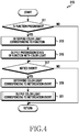
- FIG. 4 is a flowchart illustrating the operation of displaying a colored light in an edge area according to an embodiment of the present disclosure.
- the controller 150 determines whether a function is progressing in step 311.
- the function may be continuously progressed. That is, even though the main area 131 is deactivated, the controller 150 may continuously progress the function.
- the controller 150 may determine a starting point and a completion point of the function.
- the function may include a health care function, a data transmission function, a data reception function, a data download function, a data upload function, a timer function, a stopwatch function, and a file reproduction function.
- the controller 150 determines the colored light 520 corresponding to the function in step 313.
- the controller 150 determines at least one of a color and a pattern corresponding to the function.
- at least one of the color and the pattern may be configured in the storage unit 140 corresponding to the function. Accordingly, the controller 150 may determine from the storage unit 140, at least one of the color and the pattern corresponding to the function.
- the controller 150 executes control to display the colored light 520 according to the progression state of the function in step 315.
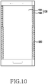
- the controller 150 may change the colored light 520 according to the amount of time the colored light is displayed. Further, the controller 150 may execute control to display the colored light 520 in the edge area 133 as shown in FIG. 10 . That is, the controller 150 may execute control to display the colored light 520 by dividing the edge area 133 into a progression section and a remaining section of the function.
- the controller 150 may determine the progression section from a starting point to a current point and determine the remaining section from the current point to a completion point.
- the controller 150 may match one end of the edge area 133 with the starting point and may match another end of the edge area 133 to the completion point such that the edge area is divided into two elongated sections whose lengths corresponds to the progress of the function. Further, the controller 150 may divide the progression section and the remaining section in the edge area 133 with the colored light 520 or display colored light in only one of the sections.
- the controller 150 may execute control to widely display a width of the colored light 520 corresponding to the progression section and may execute control to narrowly display a width of the colored light 520 corresponding to the remaining section.
- the controller 150 may execute control to narrowly display a width of the colored light 520 corresponding to the progression section and may execute control to widely display a width of the colored light 520 corresponding to the remaining section.
- the controller 150 may execute control to display the colored light 520 corresponding to the progression section and may not execute control to display the colored light 520 corresponding to the remaining section.
- the controller 150 may not execute control to display the colored light 520 corresponding to the progression section and may execute control to display the colored light 520 corresponding to the remaining section.
- the controller 150 may execute control to display the colored light 520 in the edge area 133 overall.
- the controller 150 detects the occurrence of the notification event in step 317.
- the controller 150 may detect the notification event while in standby. That is, the controller 150 may generate the notification event while in standby as shown in FIG. 9 .
- the controller 150 may detect the notification event. That is, the controller 150 may generate the notification event while executing control to display the progression state of the function with the colored light as shown in FIG. 10 .
- the notification event includes a communication event and a schedule event.
- the communication event may occur in the communication unit 110.
- the communication unit 110 may generate the communication event.
- the communication unit 110 may receive a message through a Short Messaging Service (SMS), a Multimedia Messaging Service (MMS), or a Social Networking Service (SNS).
- SMS Short Messaging Service
- MMS Multimedia Messaging Service
- SNS Social Networking Service
- the schedule event may occur in the controller 150.
- the controller 150 recognizes the schedule event or alarm.
- a specific time may be set as a schedule event or an alarm and that time is stored in the storage unit 140. Accordingly, the controller 150 can retrieve the set time of a schedule event or an alarm from the storage unit 140.
- the controller 150 determines the colored light 520 corresponding to the notification event in step 319.
- the controller 150 may determine the colored light 520 according to attributes of the notification event. Further, the controller 150 may determine the colored light 520 according to the caller of the communication event. Also, the controller 150 may determine at least one of a color and a pattern corresponding to the notification event. Herein, at least one of the color and the pattern may be configured in the storage unit 140 corresponding to the notification event. Accordingly, the controller 150 may determine, from the storage unit 140, at least one of the color and the pattern corresponding to the notification event.
- the controller 150 executes control to display the colored light 520 corresponding to the communication event in step 321.
- the controller 150 executes control to display the colored light 520 in the edge area 133 overall as shown in FIG. 11 .
- a width of the colored light 520 may be narrower than a width of the edge area 133.
- FIG. 5 is a flowchart illustrating the operation of displaying a colored light according to an embodiment of the present disclosure.
- the controller 150 executes control to display a notice window 515 in the main area 131 in step 331.
- the controller 150 may activate the main area 131.
- the controller 150 may activate a part the main area 131. That is, the controller 150 may not activate the main area 131 overall and activate only a part of area of the main area 131.
- the controller 150 executes control to display the notice window 515 as shown in FIG. 12A .
- the controller 150 executes control to display the notice window 515 through a pop-up window.
- the controller 150 executes control to display notice information in the notice window 515.
- the controller 150 may execute control to display at least a part of the information of the notification event as the notice information.
- the controller 150 detects the elapsing of time in step 333. Further, the controller 150 removes the notice window 515 from the main area 131 in step 335. That is, the controller 150 executes control to display the notice window 515 in the main area 131 during a determined time interval, and then removes the notice window 515 from the main area 131. The controller 150 may again deactivate the main area 131. Also, the controller 150 executes control to display a colored light 520 in the edge area 131. The controller 150 executes control to display the colored light 520 in the edge area 133 as shown in FIG. 12B . Herein, a width of the colored light 520 may be narrower than a width of the edge area 133. Further, the width of the colored light 520 may be identical to the width of the edge area 133. Then, the controller 150 returns executing the operations shown in the flowchart in FIG. 4 .
- FIG. 6 is a flowchart illustrating the operation of displaying a colored light in FIG. 4 .
- the controller 150 executes control to display the colored light 520 corresponding to the notification event in step 341.
- the controller 150 executes control to display the colored light 520 in the edge area 133 as shown in FIGs. 11 and 12B .
- a width of the colored light 520 may be narrower than a width of the edge area 133.
- the controller 150 detects the elapse of time in step 343. In addition, the controller 150 determines whether the colored light 520 can be extended in step 345.
- the controller 150 may compare a current width and a threshold width of the colored light 520.
- the threshold width may be configured in the storage unit 140. For example, the threshold width may exceed a width of the edge area 133.
- the controller 150 extends the colored light 520 in step 347.
- the controller 150 may determine that the colored light 520 is allowed to be extended. Further, the controller 150 extends the colored light 520 as shown in FIG. 13A and 13B .
- the controller 150 may extend a width of the colored light 520 to correspond to a width of the edge area 133.
- the controller 150 may extend the width of the colored light 520 from the edge area 133 to the main area 131. That is, the controller 150 may execute control to display the colored light 520 to the main area 131 as well as the edge area 133.
- the controller 150 may activate the main area 131.
- the controller 150 may activate part of the main area 131. Then, the controller 150 returns to step 345.
- the controller 150 may repeat at least one of step 345 and step 347. Herein, until a current width of the colored light 520 reaches a threshold width, the controller 150 may repeat steps 345 and 347. In addition, the controller 150 extends the colored light 520 as shown in FIG. 13A and then extends the colored light 520 as shown in FIG. 13B .
- the controller 150 When it is determined that the colored light 520 cannot be extended in step 345, the controller 150 returns to executing the operations shown in the flowchart in FIG. 4 .
- the controller 150 When it is determined that the current width of the colored light 520 reaches the threshold width, the controller 150 does not extend the width of the colored light 520. That is, the controller 150 maintains a width of the colored light 520.
- the controller 150 may repeat step 213.
- another notification event may be generated. That is, as shown in FIGs. 11 and 12A , another notification event may be generated while the colored light 520 is displayed in the edge area 133.
- the controller 150 may change the colored light 520 in the edge area 133.
- the controller 150 may determine at least one of a color and a pattern corresponding to another notification event.
- the controller 150 may execute control to display the colored light 520 corresponding to another notification event. That is, the controller 150 executes control to display the colored light 520 in the edge area 133 overall as shown in FIG. 14 .
- the controller 150 executing control to display the colored light 520 in the edge area 133 overall has been described, but it is not limited thereto.
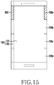
- the controller 150 executes control to partially display the colored light 520 in the edge area 133 as shown in FIG. 15 .
- the edge area 133 includes a plurality of sections 133a, 133b, 133c, and 133d. That is, the controller 150 executes control to display the colored light 520 in one section among the sections 133a, 133b, 133c, and 133d of the edge area 133.
- the controller 150 determines one section among the sections 133a, 133b, 133c, and 133d in accordance with the notification event in step 319 of FIG. 4 .
- the controller 150 determines one section among the sections 133a, 133b, 133c, and 133d according to an attribute of the notification event. Further, the controller 150 determines one section among the sections 133a, 133b, 133c, and 133d according to a caller of the communication event.
- the sections 133a, 133b, 133c, and 133d may be configured in the storage unit 140, to correspond to a plurality of callers, respectively. To this end, the controller 150 may determine in the storage unit 140, one section among the sections 133a, 133b, 133c, and 133d according to the caller of the notification event, e.g., a first caller.
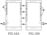
- the controller 150 changes the colored light 520 in the edge area 133 corresponding to another notification event, however, it is not limited thereto. That is, as shown in FIGs. 11 , 12A , and FIG. 15 , another notification event may be generated while the colored light 520 is displayed in the edge area 133.
- the controller 150 determines, on the basis of the storage unit 140, one section among the sections 133a, 133b, 133c, and 133d in accordance to a caller of another notification event, e.g., a second caller. Accordingly, the controller 150 may additionally execute control to display the colored light 520 in another one of the sections 133a, 133b, 133c, and 133d in the edge area 133 as shown in FIGs. 16A and 16B .
- the controller 150 may execute control to display the colored light 520 to one section corresponding to the first caller among the sections 133a, 133b, 133c, and 133d of the edge area 133.
- the controller 150 may execute control to display the colored light 520 to another section corresponding to the second caller among the sections 133a, 133b, 133c, and 133d of the edge area 133.
- the controller 150 may execute control to display the colored light 520 to another section corresponding to the second caller among the sections 133a, 133b, 133c, and 133d of the edge area 133.
- the controller 150 detects the movement in step 215.
- the controller 150 detects the generated touch.
- the controller 150 may activate the input unit 120 corresponding to the main area 131. Then, when the movement of the touch from the edge area 133 to the main area 131 is generated, the controller 150 may detect the generated movement.
- the controller 150 executes control to display data in the main area 131 in step 217.
- the controller 150 activates the main area 131.
- the controller 150 may activate a part of the main area 131.
- the controller 150 may remove the colored light 520 from the edge area 133.
- the controller 150 may execute control to display the notice window 530 in the main area 131.
- the controller 150 may extend the notice window 530 according to a movement path of the touch.
- the controller 150 may execute control to display notice information in the notice window 530.
- the controller 150 may execute control to display an execution screen 540 of the function in the main area 131.
- FIG. 7 an operation that the controller 150 executes control to display data in the main area 131 will be described in more detail.
- FIG. 7 is a flowchart illustrating the operation of displaying data to a main area of a display.
- the controller 150 detects a position and a movement distance of a touch in step 411.
- the controller 150 continuously detects positions of the touch.
- the controller 150 may detect the movement distance of the touch using the positions of the touch.
- the controller 150 may detect the movement distance of the touch by connecting the positions of the touch.
- the controller 150 may detect the movement distance of the touch by connecting specific coordinate values, for example, x-axis coordinate values in the positions of the touch.
- the controller 150 determines the movement path of the touch.
- the controller 150 may determine the movement distance of the touch by connecting the positions of the touch.
- the controller 150 executes control to display the notice window 530 in the main area 131 in step 413.
- the controller 150 activates the main area 131.
- the controller 150 may activate a part of the main area 131. That is, the controller 150 may not activate the main area 131 overall and activate only a part of the main area 131.
- the controller 150 may extend the notice window 530 according to a movement path of the touch.
- the controller 150 determines whether the movement distance of the touch reaches a notice distance in step 415. That is, the controller 150 compares the movement distance of the touch with the notice distance.
- the notice distance may be configured in the storage unit 140. Further, the notice distance may include a plurality of configuration values. For example, the notice distance may be less than the width of the main area 131.
- the controller 150 determines the notice information corresponding to the colored light 520 in step 417.
- the controller 150 may determine the notice information according to the position and the movement distance of the touch. Herein, the controller 150 may determine the notice information corresponding to one among configuration values of the notice distance.
- the controller 150 may determine at least a part of information of the function as the notice information.
- the controller 150 may determine at least a part of information of the notification event as the notice information. Further, the controller 150 may remove the colored light 520 from the edge area 133. Then, the controller 150 executes control to display the notice information in the notice window 530 in step 419.
- the controller 150 determines whether the movement distance of the touch reaches a display distance in step 421. That is, the controller 150 compares the movement distance of the touch with the display distance.
- the display distance may be configured in the storage unit 140. For example, the display distance exceeds the notice distance and may be less than or equal to the width of the main area 131.
- the controller 150 removes the notice window 530 from the main area 131 in step 423. Further, the controller 150 executes control to display, in the main area 131, the execution screen 540 of the function corresponding to the colored light 520.
- the controller 150 may activate the main area 131 overall.
- the execution screen 540 may be different according to the touch position.
- the controller 150 may execute control to display the execution screen 540 of a corresponding function. Further, the controller 150 may execute control to display the execution screen 540 of the function corresponding to the notification event. Even though the release of the touch is detected while the execution screen 540 is displayed, the controller 150 executes control to continuously display the execution screen 540.
- the controller 150 returns to executing the operations shown in the flowchart in FIG. 3 .
- the display of the notice window, the display of the execution screen or any other information of functionality may also be performed in response to touches with respect to the edge area that meet one or more criteria such as touch speed, touch duration and touch patterns for example.
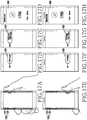
- the controller 150 may execute control to output display data in the main area 131 as shown in FIGs. 17A-17H .
- the controller 150 when a movement of a touch has been detected in the upper half of the main area 131 as shown in FIG. 17A , the controller 150 extends the notice window 530 in the upper half of the main area 131 according to a movement distance of the touch as shown in FIGs. 17B and 17C .
- the controller 150 executes control to display notice information on the remaining section in the progress state of the health care function. For example, the controller 150 may display the remaining step count in comparison with a goal step count in the notice window 530 as shown in FIG. 17B .
- the controller 150 adds and displays the goal step count in the notice window 530 as shown in FIG. 17C .
- the controller 150 executes control to display an execution screen 540 of the health care function as shown in FIG. 17D .
- the controller 150 When a movement of a touch has been detected in the lower half of the main area 131 as shown in FIG. 17E , the controller 150 extends the notice window 530 in the lower half of the main area 131 according to a movement distance of the touch as shown in FIGs. 17F and 17G .
- the controller 150 determines notice information on the progression section in the progress state of the health care function. For example, the controller 150 executes control to display a current step count in the notice window 530 as shown in FIG. 17F .
- the controller 150 executes control to add and display a distance and a calorie consumption amount, which are calculated from the current step count, in the notice window 530 as shown in FIG. 17G .
- the controller 150 executes control to display the execution screen 540 of the health care function as shown in FIG. 17H .
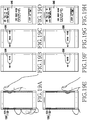
- the controller 150 executes control to display data in the main area 131 as shown in FIG. 18 .
- the controller 150 when a movement of a touch has been detected in the upper half of the main area 131 as shown in FIG. 18A , the controller 150 extends the notice window 530 in the upper half of the main area 131 according to a movement distance of the touch as shown in FIGs. 18B and 18C .
- the controller 150 executes control to display notice information on the remaining section in the progress state of the data download function. For example, the controller 150 executes control to display identification information and the remaining amount of a downloaded folder in the notice window 530 as shown in FIG. 18B .
- the controller 150 executes control to add and display the remaining time in the notice window 530 as shown in FIG. 18C .
- the controller 150 executes control to display an execution screen 540 of the data download function as shown in FIG. 18D .
- the controller 150 When a movement of a touch has been detected in the lower half of the main area 131 as shown in FIG. 18E , the controller 150 extends a notice window 530 in the lower half of the main area 131 according to a movement distance of the touch as shown in FIGs. 18F and 18G .
- the controller 150 determines notice information on a progression section in the progress state of the data download function. For example, the controller 150 executes control to display identification information and a progression amount of a downloaded folder in the notice window 530 as shown in FIG. 18F .
- the controller 150 executes control to add and display a size of the downloaded folder in the notice window 530 as shown in FIG. 18G .
- the controller 150 executes control to display an execution screen 540 of the data download function as shown in FIG. 18H .
- the controller 150 executes control to display data in the main area 131 as shown in FIG. 19 .
- the controller 150 extends the notice window 530 in the upper half of the main area 131 according to a movement distance of the touch as shown in FIGs. 19B and 19C .
- the controller 150 determines notice information on the remaining section in the progress state of the timer function. For example, the controller 150 executes control to display the remaining time in the notice window 530 as shown in FIG. 19B .
- the controller 150 executes control to add and display a goal time in the notice window 530 as shown in FIG. 19C .
- the controller 150 executes control to display an execution screen 540 of the timer function as shown in FIG. 19D .
- the controller 150 When a movement of a touch has been detected in the lower half of the main area 131 as shown in FIG. 19E , the controller 150 extends the notice window 530 in the lower half of the main area 131 according to a movement distance of the touch as shown in FIGs. 19F and 19G .
- the controller 150 determines notice information on a progression section in the progress state of the timer function. For example, the controller 150 executes control to display a progression time in the notice window 530 as shown in FIG. 19F .
- the controller 150 executes control to add and display a goal time in the notice window 530 as shown in FIG. 19G .
- the controller 150 executes control to display an execution screen 540 of the timer function as shown in FIG. 19H .
- the controller 150 executes control to display data in the main area 131 as shown in FIG. 20 .
- the controller 150 extends the notice window 530 in the upper half of the main area 131 according to a movement distance of the touch as shown in FIGs. 20B and 20C .
- the controller 150 determines notice information on the remaining section in the progress state of the file reproduction function. For example, the controller 150 executes control to display a file name and the remaining time in the notice window 530 as shown in FIG. 20B .
- the controller 150 executes control to add and display a total reproduction time in the notice window 530 as shown in FIG. 20C .
- the controller 150 executes control to display an execution screen 540 of the file reproduction function as shown in FIG. 20D .
- the controller 150 When a movement of a touch has been detected in the lower half of the main area 131 as shown in FIG. 20E , the controller 150 extends a notice window 530 in the lower half of the main area 131 according to a movement distance of the touch as shown in FIGs. 20F and 20G .
- the controller 150 determines notice information on a progression section in the progress state of the file reproduction function. For example, the controller 150 executes control to display a file name and a progression time in the notice window 530 as shown in FIG. 20F .
- the controller 150 executes control to add and display a total reproduction time in the notice window 530 as shown in FIG. 20G .
- the controller 150 executes control to display an execution screen 540 of the file reproduction function as shown in FIG. 20H .
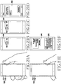
- the controller 150 executes control to display data in the main area 131 as shown in FIG. 21 .
- the controller 150 when a movement of a touch has been detected in the upper half of the main area 131 as shown in FIG. 21A , the controller 150 extends the notice window 530 in the upper half of the main area 131 according to a movement distance of the touch as shown in FIGs. 21B and 21C .
- the controller 150 determines notice information corresponding to a message. For example, the controller 150 executes control to display identification information in the notice window 530 as shown in FIG. 21B .
- the controller 150 executes control to add and display at least a part of a message content in the notice window 530 as shown in FIG. 21C .
- the controller 150 executes control to display an execution screen 540 of a message exchange function as shown in FIG. 21D .
- the controller 150 executes control to display the execution screen 540 of the message exchange function as shown in FIG. 21F .
- the controller 150 executes control to add and display a keypad 550 on the execution screen 540.
- the controller 150 executes control to continuously display the notice window 530 in the main area 131. Similarly, when the movement distance of the touch does not reach the display distance in step 421, the controller 150 executes control to continuously display the notice window 530 in the main area 131.
- the controller 150 detects the release of the touch in step 425. Further, the controller 150 removes the notice window 530 from the main area 131 in step 427. That is, when the touch is released in moving in the main area 131, the controller 150 removes the notice window 530 from the main area 131.
- the controller 150 may again deactivate the main area 131. After the movement of the touch reaches the notice distance, when the touch is released, the controller 150 may continuously output the colored light 520 in the edge area 133. Then, the controller 150 returns to executing the operations shown in the flowchart of FIG. 3 .
- the controller 150 When deactivation of the main area 131 has not been detected in step 211, the controller 150 performs a corresponding function in step 221.
- the controller 150 executes control to continuously display a display screen in the main area 131 as shown in FIG. 8 .
- the controller 150 executes control to perform a function and continuously display an execution screen 510 of the function in the main area 131.
- the controller 150 may configure and change various pieces of configuration information as new information. For example, the controller 150 may configure and change the configuration information as new information corresponding to a user input.
- the display unit 130 of the electronic device 100 includes the main area 131 and the edge area 133.
- the electronic device 100 displays a colored light through the edge area 133, thereby providing a notice for the information. Therefore, it can prevent causing annoyance to a person who is not a user of the electronic device 100. Further, it can help secure the information and prevent the information from being exposed to a person who is not the user of the electronic device 100.
- the electronic device 100 may apply a color, a pattern, or a position in the edge area 133 to the colored light, thereby distinguishing the information. Accordingly, the electronic device 100 can effectively provide a notice for the information. Therefore, the electronic device 100 may efficiently display the information.
- embodiments of the present disclosure can be realized in the form of hardware, software or a combination of hardware and software. Any such software may be stored in the form of volatile or non-volatile storage such as, for example, a storage device like a ROM, whether erasable or rewritable or not, or in the form of memory such as, for example, RAM, memory chips, device or integrated circuits or on an optically or magnetically readable medium such as, for example, a CD, DVD, magnetic disk or magnetic tape or the like. It will be appreciated that the storage devices and storage media are embodiments of machine-readable storage that are suitable for storing a program or programs comprising instructions that, when executed, implement embodiments of the present disclosure.
- embodiments provide a program comprising code for implementing apparatus or a method as claimed in any one of the claims of this specification and a machine-readable storage storing such a program. Still further, such programs may be conveyed electronically via any medium such as a communication signal carried over a wired or wireless connection and embodiments suitably encompass the same.
Landscapes
- Engineering & Computer Science (AREA)
- Theoretical Computer Science (AREA)
- General Engineering & Computer Science (AREA)
- Human Computer Interaction (AREA)
- Physics & Mathematics (AREA)
- General Physics & Mathematics (AREA)
- Signal Processing (AREA)
- Computer Networks & Wireless Communication (AREA)
- User Interface Of Digital Computer (AREA)
- Telephone Function (AREA)
- Controls And Circuits For Display Device (AREA)
Claims (13)
- Elektronische Einheit (100), aufweisend:eine Anzeigeeinheit (130) mit einem Hauptbereich (131) und einem Randbereich (133), der sich von dem Hauptbereich (131) aus erstreckt und in eine Mehrzahl von Abschnitten (133a bis 133d) unterteilt ist;und einen Controller (150), der funktionsfähig mit der Anzeigeeinheit (130) verbunden ist, wobei der Controller (150) konfiguriert ist, um ein Benachrichtigungsereignis zu erkennen, mindestens einen Abschnitt des Randbereichs von den Abschnitten (133) der Anzeigeeinheit (130) zu bestimmen, der dem Benachrichtigungsereignis entspricht, und die Anzeigeeinheit (130) zu steuern, ein farbiges Licht (520) in dem bestimmten Abschnitt anzuzeigen, wobei die Abschnitte (133a bis 133d) den vorbestimmten Anrufern gemäß einer Position in dem Randbereich (133) entsprechen.
- Elektronische Einheit (100) nach Anspruch 1, wobei der Controller (150) konfiguriert ist, um den Anrufer zu bestimmen, der dem Benachrichtigungsereignis entspricht, und um mindestens einen Abschnitt von den Abschnitten (133a bis 133d) zu bestimmen, der dem bestimmten Anrufer entspricht.
- Elektronische Einheit (100) nach einem der vorhergehenden Ansprüche, wobei die Abschnitte (133a bis 133d) vorbestimmten Farben entsprechen.
- Elektronische Einheit (100) nach Anspruch 2, wobei der Controller (150) konfiguriert ist, um eine Berührungsbewegung von dem bestimmten Randbereich zum Hauptbereich (131) zu erkennen und die Anzeigeeinheit (130) zu steuern, ein Hinweisfenster mit Hinweisinformationen des Benachrichtigungsereignisses in dem Hauptbereich (131) anzuzeigen, wobei das Hinweisfenster sich entsprechend einem Bewegungspfad der Berührung in dem Hauptbereich (131) erstreckt.
- Elektronische Einheit (100) nach Anspruch 4, wobei der Controller (150) konfiguriert ist, um das Hinweisfenster aus dem Hauptbereich (131) zu entfernen und die Anzeigeeinheit (130) zu steuern, einen Ausführungsbildschirm einer Funktion anzuzeigen, die dem Benachrichtigungsereignis in dem Hauptbereich (131) entspricht.
- Elektronische Einheit (100) nach Anspruch 4, wobei die Hinweisinformationen Identifizierungsinformationen des bestimmten Anrufers enthalten.
- Betriebsverfahren einer elektronischen Einheit (100), aufweisend:ein Erkennen eines Benachrichtigungsereignisses;ein Bestimmen von mindestens einem Abschnitt einer Anzeigeeinheit (130), der dem Benachrichtigungsereignis entspricht, von einer Mehrzahl von Abschnitten (133a bis 133d) eines Randbereichs (133) der Anzeigeeinheit, der sich von einem Hauptbereich (131) der Anzeigeeinheit (130) erstreckt; und ein Anzeigen eines farbigen Lichts (520) in dem bestimmten Abschnitt, wobei die Abschnitte (133a bis 133d) vorbestimmten Anrufern gemäß einer Position in dem Randbereich (133) entsprechen.
- Betriebsverfahren nach Anspruch 7, wobei ein Bestimmen des mindestens einen Abschnitts aufweist:
ein Bestimmen eines Anrufers, der dem Benachrichtigungsereignis entspricht; und ein Bestimmen von mindestens einem Abschnitt der Anzeigeeinheit (130) von den Abschnitten (133a bis 133d), der dem bestimmten Anrufer entspricht. - Betriebsverfahren nach einem der Ansprüche 7 bis 8, wobei die Abschnitte (133a bis 133d) vorbestimmten Farben entsprechen.
- Betriebsverfahren nach Anspruch 8, ferner aufweisend:
eine Erkennen einer Berührungsbewegung von dem bestimmten Abschnitt zu dem Hauptbereich (131); und ein Anzeigen eines Hinweisfensters mit Hinweisinformationen des Benachrichtigungsereignisses in dem Hauptbereich (131). - Betriebsverfahren nach Anspruch 10, wobei ein Anzeigen des Hinweisfensters ein Erweitern des Hinweisfensters gemäß einem Bewegungspfad der Berührung in dem Hauptbereich (131) aufweist.
- Betriebsverfahren nach Anspruch 10, ferner aufweisend ein Entfernen des Hinweisfensters in dem Hauptbereich (131);
und ein Anzeigen eines Ausführungsbildschirms einer Funktion, die dem Benachrichtigungsereignis in dem Hauptbereich (131) entspricht. - Betriebsverfahren nach Anspruch 10, wobei die Hinweisinformationen Identifizierungsinformationen des bestimmten Anrufers enthalten.
Applications Claiming Priority (1)
| Application Number | Priority Date | Filing Date | Title |
|---|---|---|---|
| KR1020150008094A KR102318227B1 (ko) | 2015-01-16 | 2015-01-16 | 정보 표시 장치 및 방법 |
Publications (2)
| Publication Number | Publication Date |
|---|---|
| EP3048518A1 EP3048518A1 (de) | 2016-07-27 |
| EP3048518B1 true EP3048518B1 (de) | 2019-09-04 |
Family
ID=55345649
Family Applications (1)
| Application Number | Title | Priority Date | Filing Date |
|---|---|---|---|
| EP16151483.1A Active EP3048518B1 (de) | 2015-01-16 | 2016-01-15 | Elektronische vorrichtung und betriebsverfahren dafür |
Country Status (5)
| Country | Link |
|---|---|
| US (1) | US10133529B2 (de) |
| EP (1) | EP3048518B1 (de) |
| KR (1) | KR102318227B1 (de) |
| MY (1) | MY187952A (de) |
| WO (1) | WO2016114620A1 (de) |
Families Citing this family (23)
| Publication number | Priority date | Publication date | Assignee | Title |
|---|---|---|---|---|
| USD784410S1 (en) * | 2015-09-02 | 2017-04-18 | Samsung Electronics Co., Ltd | Display screen or portion thereof with transitional graphical user interface |
| US11354008B2 (en) * | 2016-08-10 | 2022-06-07 | Microsoft Technology Licensing, Llc | Visual notification |
| USD806736S1 (en) * | 2016-10-03 | 2018-01-02 | Google Llc | Display screen with animated graphical user interface |
| USD807387S1 (en) * | 2016-10-03 | 2018-01-09 | Google Llc | Display screen with animated graphical user interface |
| USD806737S1 (en) * | 2016-10-03 | 2018-01-02 | Google Llc | Display screen with graphical user interface |
| JP6828134B2 (ja) * | 2017-02-22 | 2021-02-10 | ソニーモバイルコミュニケーションズ株式会社 | 情報処理装置、方法およびプログラム |
| KR102673224B1 (ko) | 2017-02-23 | 2024-06-10 | 삼성전자주식회사 | 전자 장치 및 전자 장치 제어 방법 |
| USD830406S1 (en) | 2017-03-31 | 2018-10-09 | Otis Elevator Company | Display screen or portion thereof with transitional graphical user interface |
| USD972576S1 (en) * | 2017-03-31 | 2022-12-13 | Otis Elevator Company | Display screen or portion thereof with graphical user interface |
| CN106990830A (zh) * | 2017-04-06 | 2017-07-28 | 深圳天珑无线科技有限公司 | 一种信息显示方法及装置 |
| KR102422491B1 (ko) | 2018-02-21 | 2022-07-19 | 삼성전자 주식회사 | 전자 장치 및 전자 장치 제어 방법 |
| USD879114S1 (en) | 2018-03-29 | 2020-03-24 | Google Llc | Display screen with graphical user interface |
| USD850483S1 (en) * | 2018-03-29 | 2019-06-04 | Google Llc | Display screen with animated graphical user interface |
| CN109068001B (zh) * | 2018-09-21 | 2021-03-09 | Oppo广东移动通信有限公司 | 提醒方法及相关设备 |
| CN109348049B (zh) * | 2018-09-28 | 2021-01-29 | Oppo广东移动通信有限公司 | 光效显示方法、相关设备及存储介质 |
| USD919632S1 (en) * | 2019-01-21 | 2021-05-18 | Promethean Limited | Display screen or portion thereof with animated graphical user interface |
| CN110740214B (zh) * | 2019-10-22 | 2021-04-13 | 维沃移动通信(杭州)有限公司 | 一种提示方法、终端及计算机可读存储介质 |
| CN110731539A (zh) * | 2019-10-28 | 2020-01-31 | 徐州启成钢结构有限公司 | 一种烟灰缸网架装置 |
| CN113160731B (zh) * | 2020-01-07 | 2024-02-09 | 敦泰电子股份有限公司 | 具警示灯功能的显示驱动器及行动装置 |
| USD999231S1 (en) * | 2021-12-02 | 2023-09-19 | PassiveLogic, Inc. | Display screen or portion thereof with a graphical user interface |
| CN114416260B (zh) * | 2022-01-20 | 2024-06-04 | 北京字跳网络技术有限公司 | 图像处理方法、装置、电子设备及存储介质 |
| EP4668088A4 (de) * | 2023-03-21 | 2026-05-20 | Samsung Electronics Co Ltd | Verfahren zur anzeige des kantenbeleuchtungseffekts und elektronische vorrichtung dafür |
| CN220629376U (zh) * | 2023-07-11 | 2024-03-19 | 深圳市得一创新技术有限公司 | 一种带rgb灯光组件的手机壳 |
Family Cites Families (22)
| Publication number | Priority date | Publication date | Assignee | Title |
|---|---|---|---|---|
| KR20020014945A (ko) * | 2000-08-19 | 2002-02-27 | 서평원 | 휴대단말기의 엘이디를 이용한 호출자 표시장치 |
| EP1227388A1 (de) | 2001-01-24 | 2002-07-31 | Inventec Appliances Corp. | Konstruktion eines berührungsempfindlichen Bildschirms |
| JP4106888B2 (ja) | 2001-09-19 | 2008-06-25 | カシオ計算機株式会社 | 液晶表示装置および携帯端末装置 |
| US7388590B2 (en) * | 2004-02-27 | 2008-06-17 | Microsoft Corporation | Method and system for using a color scheme to communicate information related to the integration of hardware and software in a computing device |
| EP1780634A3 (de) | 2005-10-26 | 2008-01-16 | Alcatel Lucent | Indexierte Verschiebung |
| US8224391B2 (en) | 2009-07-20 | 2012-07-17 | Lg Electronics Inc. | Mobile terminal having an LED backlight unit |
| KR101633329B1 (ko) | 2009-08-19 | 2016-06-24 | 엘지전자 주식회사 | 이동 단말기 및 그 제어방법 |
| US8195254B2 (en) * | 2009-12-22 | 2012-06-05 | Nokia Corporation | Apparatus comprising a sliding display part |
| CN103270486A (zh) * | 2010-11-18 | 2013-08-28 | 谷歌公司 | 滚动条上的正交拖拉 |
| US9471145B2 (en) * | 2011-01-06 | 2016-10-18 | Blackberry Limited | Electronic device and method of displaying information in response to a gesture |
| KR101935038B1 (ko) * | 2011-02-23 | 2019-01-03 | 엘지전자 주식회사 | 이동 단말기 및 이동 단말기의 제어 방법 |
| KR101914069B1 (ko) * | 2011-11-02 | 2018-11-01 | 삼성전자 주식회사 | 터치 스크린을 구비한 단말 및 그 단말에서 데이터 표시 방법 |
| WO2013118522A1 (ja) * | 2012-02-08 | 2013-08-15 | Necカシオモバイルコミュニケーションズ株式会社 | 携帯端末及びその動作方法 |
| US8583198B1 (en) * | 2012-04-18 | 2013-11-12 | Thomas E. Coverstone | Active cover for electronic device |
| US9300347B1 (en) * | 2012-04-18 | 2016-03-29 | Star Co Scientific Technologies Advanced Research Co, Llc | Active cover for electronic device |
| CN102799382A (zh) | 2012-07-16 | 2012-11-28 | 华为终端有限公司 | 用户设备的系统栏的控制方法和用户设备 |
| KR20140106201A (ko) * | 2013-02-26 | 2014-09-03 | 한국전자통신연구원 | 알림창을 표시하는 디스플레이 장치 및 디스플레이 장치의 서비스 실행방법 |
| US9690476B2 (en) * | 2013-03-14 | 2017-06-27 | Blackberry Limited | Electronic device and method of displaying information in response to a gesture |
| KR20140136633A (ko) | 2013-05-21 | 2014-12-01 | 삼성전자주식회사 | 휴대형 전자장치의 애플리케이션 실행 방법 및 그에 관한 장치 |
| US9467558B2 (en) * | 2013-06-14 | 2016-10-11 | Lg Electronics Inc. | Mobile terminal and controlling method thereof |
| US9531422B2 (en) * | 2013-12-04 | 2016-12-27 | Lg Electronics Inc. | Mobile terminal and control method for the mobile terminal |
| KR102199806B1 (ko) * | 2013-12-05 | 2021-01-07 | 삼성전자주식회사 | 곡형 디스플레이 모듈을 갖는 전자 장치 및 그 운용 방법 |
-
2015
- 2015-01-16 KR KR1020150008094A patent/KR102318227B1/ko active Active
-
2016
- 2016-01-15 US US14/996,703 patent/US10133529B2/en active Active
- 2016-01-15 EP EP16151483.1A patent/EP3048518B1/de active Active
- 2016-01-15 WO PCT/KR2016/000439 patent/WO2016114620A1/en not_active Ceased
- 2016-01-15 MY MYPI2017702570A patent/MY187952A/en unknown
Non-Patent Citations (1)
| Title |
|---|
| None * |
Also Published As
| Publication number | Publication date |
|---|---|
| MY187952A (en) | 2021-10-31 |
| US10133529B2 (en) | 2018-11-20 |
| KR20160088693A (ko) | 2016-07-26 |
| US20160224299A1 (en) | 2016-08-04 |
| EP3048518A1 (de) | 2016-07-27 |
| WO2016114620A1 (en) | 2016-07-21 |
| KR102318227B1 (ko) | 2021-10-27 |
Similar Documents
| Publication | Publication Date | Title |
|---|---|---|
| EP3048518A1 (de) | Elektronische vorrichtung und betriebsverfahren dafür | |
| US12056341B2 (en) | Method, apparatus, and terminal for processing notification information | |
| JP5819403B2 (ja) | 電子機器、操作制御方法および操作制御プログラム | |
| US9100944B2 (en) | Wireless connecting mobile devices and wearable devices | |
| KR20130105235A (ko) | 중앙 집중식 애플리케이션 알림을 위한 방법 및 장치 | |
| EP2993584B1 (de) | Verfahren und vorrichtung zur steuerung einer hintergrundanwendung | |
| EP3016451B1 (de) | Elektronische vorrichtung und verfahren zur steuerung der leistung eines hintergrunds einer elektronischen vorrichtung | |
| US20160085397A1 (en) | Smart Watch Notification Manager | |
| KR20110093528A (ko) | 에스엔에스 위젯 제공 방법 및 그 장치 | |
| KR20180067589A (ko) | 애플리케이션의 사용을 제한하는 방법 및 단말기 | |
| US20140282174A1 (en) | Silence reminder | |
| CN105144061A (zh) | 屏幕控制方法及其电子设备 | |
| KR20140080090A (ko) | 휴대단말기의 사용 방법 및 장치 | |
| KR20130091508A (ko) | 사용자 디바이스의 옵션 설정 방법 및 장치 | |
| CN103294442A (zh) | 一种播放提示音的方法、装置及终端设备 | |
| JP6900552B2 (ja) | アプリケーションの使用を制限する方法、および端末 | |
| EP3142053A1 (de) | Elektronische vorrichtung und betriebsverfahren dafür | |
| US20120231854A1 (en) | Mobile terminal device and function setting method for mobile terminal device | |
| US9710301B2 (en) | Storage medium storing computer program, information processing system, and information processing method | |
| TR201702274A2 (tr) | Bi̇r i̇şlemci̇ ci̇hazinin ön tanimli bi̇r kullanimi sirasinda bi̇ldi̇ri̇mleri̇n seçi̇ci̇ şeki̇lde önlenmesi̇ i̇çi̇n yöntem | |
| US20190087147A1 (en) | Mobile device and method for operating mobile device | |
| KR101398183B1 (ko) | 하드웨어 입력기를 이용한 스마트폰의 거울 애플리케이션의 다이렉트 실행 방법 및 그런 기능을 갖는 스마트폰 | |
| US20120227003A1 (en) | Electronic device with function of distinguishing working state of option menus and method thereof | |
| KR20130024583A (ko) | 휴대 단말과 확장 장치의 연결에 따른 휴대 단말 제어 방법 및 시스템 | |
| CN107545198A (zh) | 一种按键管理方法和装置 |
Legal Events
| Date | Code | Title | Description |
|---|---|---|---|
| PUAI | Public reference made under article 153(3) epc to a published international application that has entered the european phase |
Free format text: ORIGINAL CODE: 0009012 |
|
| 17P | Request for examination filed |
Effective date: 20160115 |
|
| AK | Designated contracting states |
Kind code of ref document: A1 Designated state(s): AL AT BE BG CH CY CZ DE DK EE ES FI FR GB GR HR HU IE IS IT LI LT LU LV MC MK MT NL NO PL PT RO RS SE SI SK SM TR |
|
| AX | Request for extension of the european patent |
Extension state: BA ME |
|
| REG | Reference to a national code |
Ref country code: DE Ref legal event code: R079 Ref document number: 602016019701 Country of ref document: DE Free format text: PREVIOUS MAIN CLASS: G06F0003048100 Ipc: G06F0003048800 |
|
| GRAP | Despatch of communication of intention to grant a patent |
Free format text: ORIGINAL CODE: EPIDOSNIGR1 |
|
| STAA | Information on the status of an ep patent application or granted ep patent |
Free format text: STATUS: GRANT OF PATENT IS INTENDED |
|
| RIC1 | Information provided on ipc code assigned before grant |
Ipc: H04M 1/21 20060101ALI20190321BHEP Ipc: H04M 19/04 20060101ALI20190321BHEP Ipc: G06F 3/14 20060101ALI20190321BHEP Ipc: H04W 68/00 20090101ALI20190321BHEP Ipc: G06F 3/0488 20130101AFI20190321BHEP Ipc: G06F 3/0481 20130101ALI20190321BHEP Ipc: H04M 1/725 20060101ALI20190321BHEP |
|
| INTG | Intention to grant announced |
Effective date: 20190405 |
|
| GRAS | Grant fee paid |
Free format text: ORIGINAL CODE: EPIDOSNIGR3 |
|
| GRAA | (expected) grant |
Free format text: ORIGINAL CODE: 0009210 |
|
| STAA | Information on the status of an ep patent application or granted ep patent |
Free format text: STATUS: THE PATENT HAS BEEN GRANTED |
|
| AK | Designated contracting states |
Kind code of ref document: B1 Designated state(s): AL AT BE BG CH CY CZ DE DK EE ES FI FR GB GR HR HU IE IS IT LI LT LU LV MC MK MT NL NO PL PT RO RS SE SI SK SM TR |
|
| REG | Reference to a national code |
Ref country code: GB Ref legal event code: FG4D |
|
| REG | Reference to a national code |
Ref country code: CH Ref legal event code: EP |
|
| REG | Reference to a national code |
Ref country code: AT Ref legal event code: REF Ref document number: 1176314 Country of ref document: AT Kind code of ref document: T Effective date: 20190915 |
|
| REG | Reference to a national code |
Ref country code: DE Ref legal event code: R096 Ref document number: 602016019701 Country of ref document: DE |
|
| REG | Reference to a national code |
Ref country code: IE Ref legal event code: FG4D |
|
| REG | Reference to a national code |
Ref country code: NL Ref legal event code: MP Effective date: 20190904 |
|
| REG | Reference to a national code |
Ref country code: LT Ref legal event code: MG4D |
|
| PG25 | Lapsed in a contracting state [announced via postgrant information from national office to epo] |
Ref country code: BG Free format text: LAPSE BECAUSE OF FAILURE TO SUBMIT A TRANSLATION OF THE DESCRIPTION OR TO PAY THE FEE WITHIN THE PRESCRIBED TIME-LIMIT Effective date: 20191204 Ref country code: SE Free format text: LAPSE BECAUSE OF FAILURE TO SUBMIT A TRANSLATION OF THE DESCRIPTION OR TO PAY THE FEE WITHIN THE PRESCRIBED TIME-LIMIT Effective date: 20190904 Ref country code: NO Free format text: LAPSE BECAUSE OF FAILURE TO SUBMIT A TRANSLATION OF THE DESCRIPTION OR TO PAY THE FEE WITHIN THE PRESCRIBED TIME-LIMIT Effective date: 20191204 Ref country code: FI Free format text: LAPSE BECAUSE OF FAILURE TO SUBMIT A TRANSLATION OF THE DESCRIPTION OR TO PAY THE FEE WITHIN THE PRESCRIBED TIME-LIMIT Effective date: 20190904 Ref country code: LT Free format text: LAPSE BECAUSE OF FAILURE TO SUBMIT A TRANSLATION OF THE DESCRIPTION OR TO PAY THE FEE WITHIN THE PRESCRIBED TIME-LIMIT Effective date: 20190904 Ref country code: HR Free format text: LAPSE BECAUSE OF FAILURE TO SUBMIT A TRANSLATION OF THE DESCRIPTION OR TO PAY THE FEE WITHIN THE PRESCRIBED TIME-LIMIT Effective date: 20190904 |
|
| PG25 | Lapsed in a contracting state [announced via postgrant information from national office to epo] |
Ref country code: LV Free format text: LAPSE BECAUSE OF FAILURE TO SUBMIT A TRANSLATION OF THE DESCRIPTION OR TO PAY THE FEE WITHIN THE PRESCRIBED TIME-LIMIT Effective date: 20190904 Ref country code: GR Free format text: LAPSE BECAUSE OF FAILURE TO SUBMIT A TRANSLATION OF THE DESCRIPTION OR TO PAY THE FEE WITHIN THE PRESCRIBED TIME-LIMIT Effective date: 20191205 Ref country code: AL Free format text: LAPSE BECAUSE OF FAILURE TO SUBMIT A TRANSLATION OF THE DESCRIPTION OR TO PAY THE FEE WITHIN THE PRESCRIBED TIME-LIMIT Effective date: 20190904 Ref country code: RS Free format text: LAPSE BECAUSE OF FAILURE TO SUBMIT A TRANSLATION OF THE DESCRIPTION OR TO PAY THE FEE WITHIN THE PRESCRIBED TIME-LIMIT Effective date: 20190904 Ref country code: ES Free format text: LAPSE BECAUSE OF FAILURE TO SUBMIT A TRANSLATION OF THE DESCRIPTION OR TO PAY THE FEE WITHIN THE PRESCRIBED TIME-LIMIT Effective date: 20190904 |
|
| REG | Reference to a national code |
Ref country code: AT Ref legal event code: MK05 Ref document number: 1176314 Country of ref document: AT Kind code of ref document: T Effective date: 20190904 |
|
| PG25 | Lapsed in a contracting state [announced via postgrant information from national office to epo] |
Ref country code: PT Free format text: LAPSE BECAUSE OF FAILURE TO SUBMIT A TRANSLATION OF THE DESCRIPTION OR TO PAY THE FEE WITHIN THE PRESCRIBED TIME-LIMIT Effective date: 20200106 Ref country code: EE Free format text: LAPSE BECAUSE OF FAILURE TO SUBMIT A TRANSLATION OF THE DESCRIPTION OR TO PAY THE FEE WITHIN THE PRESCRIBED TIME-LIMIT Effective date: 20190904 Ref country code: IT Free format text: LAPSE BECAUSE OF FAILURE TO SUBMIT A TRANSLATION OF THE DESCRIPTION OR TO PAY THE FEE WITHIN THE PRESCRIBED TIME-LIMIT Effective date: 20190904 Ref country code: PL Free format text: LAPSE BECAUSE OF FAILURE TO SUBMIT A TRANSLATION OF THE DESCRIPTION OR TO PAY THE FEE WITHIN THE PRESCRIBED TIME-LIMIT Effective date: 20190904 Ref country code: NL Free format text: LAPSE BECAUSE OF FAILURE TO SUBMIT A TRANSLATION OF THE DESCRIPTION OR TO PAY THE FEE WITHIN THE PRESCRIBED TIME-LIMIT Effective date: 20190904 Ref country code: AT Free format text: LAPSE BECAUSE OF FAILURE TO SUBMIT A TRANSLATION OF THE DESCRIPTION OR TO PAY THE FEE WITHIN THE PRESCRIBED TIME-LIMIT Effective date: 20190904 Ref country code: RO Free format text: LAPSE BECAUSE OF FAILURE TO SUBMIT A TRANSLATION OF THE DESCRIPTION OR TO PAY THE FEE WITHIN THE PRESCRIBED TIME-LIMIT Effective date: 20190904 |
|
| PG25 | Lapsed in a contracting state [announced via postgrant information from national office to epo] |
Ref country code: IS Free format text: LAPSE BECAUSE OF FAILURE TO SUBMIT A TRANSLATION OF THE DESCRIPTION OR TO PAY THE FEE WITHIN THE PRESCRIBED TIME-LIMIT Effective date: 20200224 Ref country code: CZ Free format text: LAPSE BECAUSE OF FAILURE TO SUBMIT A TRANSLATION OF THE DESCRIPTION OR TO PAY THE FEE WITHIN THE PRESCRIBED TIME-LIMIT Effective date: 20190904 Ref country code: SK Free format text: LAPSE BECAUSE OF FAILURE TO SUBMIT A TRANSLATION OF THE DESCRIPTION OR TO PAY THE FEE WITHIN THE PRESCRIBED TIME-LIMIT Effective date: 20190904 Ref country code: SM Free format text: LAPSE BECAUSE OF FAILURE TO SUBMIT A TRANSLATION OF THE DESCRIPTION OR TO PAY THE FEE WITHIN THE PRESCRIBED TIME-LIMIT Effective date: 20190904 |
|
| REG | Reference to a national code |
Ref country code: DE Ref legal event code: R097 Ref document number: 602016019701 Country of ref document: DE |
|
| PLBE | No opposition filed within time limit |
Free format text: ORIGINAL CODE: 0009261 |
|
| STAA | Information on the status of an ep patent application or granted ep patent |
Free format text: STATUS: NO OPPOSITION FILED WITHIN TIME LIMIT |
|
| PG2D | Information on lapse in contracting state deleted |
Ref country code: IS |
|
| PG25 | Lapsed in a contracting state [announced via postgrant information from national office to epo] |
Ref country code: DK Free format text: LAPSE BECAUSE OF FAILURE TO SUBMIT A TRANSLATION OF THE DESCRIPTION OR TO PAY THE FEE WITHIN THE PRESCRIBED TIME-LIMIT Effective date: 20190904 Ref country code: IS Free format text: LAPSE BECAUSE OF FAILURE TO SUBMIT A TRANSLATION OF THE DESCRIPTION OR TO PAY THE FEE WITHIN THE PRESCRIBED TIME-LIMIT Effective date: 20200105 |
|
| 26N | No opposition filed |
Effective date: 20200605 |
|
| PG25 | Lapsed in a contracting state [announced via postgrant information from national office to epo] |
Ref country code: MC Free format text: LAPSE BECAUSE OF FAILURE TO SUBMIT A TRANSLATION OF THE DESCRIPTION OR TO PAY THE FEE WITHIN THE PRESCRIBED TIME-LIMIT Effective date: 20190904 Ref country code: SI Free format text: LAPSE BECAUSE OF FAILURE TO SUBMIT A TRANSLATION OF THE DESCRIPTION OR TO PAY THE FEE WITHIN THE PRESCRIBED TIME-LIMIT Effective date: 20190904 |
|
| REG | Reference to a national code |
Ref country code: CH Ref legal event code: PL |
|
| GBPC | Gb: european patent ceased through non-payment of renewal fee |
Effective date: 20200115 |
|
| REG | Reference to a national code |
Ref country code: BE Ref legal event code: MM Effective date: 20200131 |
|
| PG25 | Lapsed in a contracting state [announced via postgrant information from national office to epo] |
Ref country code: FR Free format text: LAPSE BECAUSE OF NON-PAYMENT OF DUE FEES Effective date: 20200131 Ref country code: LU Free format text: LAPSE BECAUSE OF NON-PAYMENT OF DUE FEES Effective date: 20200115 Ref country code: GB Free format text: LAPSE BECAUSE OF NON-PAYMENT OF DUE FEES Effective date: 20200115 |
|
| PG25 | Lapsed in a contracting state [announced via postgrant information from national office to epo] |
Ref country code: LI Free format text: LAPSE BECAUSE OF NON-PAYMENT OF DUE FEES Effective date: 20200131 Ref country code: CH Free format text: LAPSE BECAUSE OF NON-PAYMENT OF DUE FEES Effective date: 20200131 Ref country code: BE Free format text: LAPSE BECAUSE OF NON-PAYMENT OF DUE FEES Effective date: 20200131 |
|
| PG25 | Lapsed in a contracting state [announced via postgrant information from national office to epo] |
Ref country code: IE Free format text: LAPSE BECAUSE OF NON-PAYMENT OF DUE FEES Effective date: 20200115 |
|
| PG25 | Lapsed in a contracting state [announced via postgrant information from national office to epo] |
Ref country code: TR Free format text: LAPSE BECAUSE OF FAILURE TO SUBMIT A TRANSLATION OF THE DESCRIPTION OR TO PAY THE FEE WITHIN THE PRESCRIBED TIME-LIMIT Effective date: 20190904 Ref country code: MT Free format text: LAPSE BECAUSE OF FAILURE TO SUBMIT A TRANSLATION OF THE DESCRIPTION OR TO PAY THE FEE WITHIN THE PRESCRIBED TIME-LIMIT Effective date: 20190904 Ref country code: CY Free format text: LAPSE BECAUSE OF FAILURE TO SUBMIT A TRANSLATION OF THE DESCRIPTION OR TO PAY THE FEE WITHIN THE PRESCRIBED TIME-LIMIT Effective date: 20190904 |
|
| PG25 | Lapsed in a contracting state [announced via postgrant information from national office to epo] |
Ref country code: MK Free format text: LAPSE BECAUSE OF FAILURE TO SUBMIT A TRANSLATION OF THE DESCRIPTION OR TO PAY THE FEE WITHIN THE PRESCRIBED TIME-LIMIT Effective date: 20190904 |
|
| PGFP | Annual fee paid to national office [announced via postgrant information from national office to epo] |
Ref country code: DE Payment date: 20251222 Year of fee payment: 11 |