EP3048425B1 - System zur messung der kontaktkraft in einem verbrauchszähler - Google Patents
System zur messung der kontaktkraft in einem verbrauchszähler Download PDFInfo
- Publication number
- EP3048425B1 EP3048425B1 EP16151753.7A EP16151753A EP3048425B1 EP 3048425 B1 EP3048425 B1 EP 3048425B1 EP 16151753 A EP16151753 A EP 16151753A EP 3048425 B1 EP3048425 B1 EP 3048425B1
- Authority
- EP
- European Patent Office
- Prior art keywords
- force
- utility meter
- contact force
- indicator
- terminal
- Prior art date
- Legal status (The legal status is an assumption and is not a legal conclusion. Google has not performed a legal analysis and makes no representation as to the accuracy of the status listed.)
- Active
Links
- 230000005611 electricity Effects 0.000 claims description 19
- 238000000034 method Methods 0.000 claims description 14
- 238000003860 storage Methods 0.000 claims description 9
- 238000012800 visualization Methods 0.000 claims description 6
- 238000012360 testing method Methods 0.000 description 10
- 238000010586 diagram Methods 0.000 description 6
- 238000005259 measurement Methods 0.000 description 5
- 238000011161 development Methods 0.000 description 4
- 230000018109 developmental process Effects 0.000 description 4
- 239000000853 adhesive Substances 0.000 description 3
- 230000001070 adhesive effect Effects 0.000 description 3
- 238000004891 communication Methods 0.000 description 3
- 230000008901 benefit Effects 0.000 description 2
- 230000007423 decrease Effects 0.000 description 2
- 230000002950 deficient Effects 0.000 description 2
- 230000001419 dependent effect Effects 0.000 description 2
- 238000013461 design Methods 0.000 description 2
- 230000001771 impaired effect Effects 0.000 description 2
- 238000011065 in-situ storage Methods 0.000 description 2
- 238000004519 manufacturing process Methods 0.000 description 2
- 239000000463 material Substances 0.000 description 2
- 238000006243 chemical reaction Methods 0.000 description 1
- 238000005260 corrosion Methods 0.000 description 1
- 230000007797 corrosion Effects 0.000 description 1
- 238000005286 illumination Methods 0.000 description 1
- 238000003780 insertion Methods 0.000 description 1
- 230000037431 insertion Effects 0.000 description 1
- 238000005461 lubrication Methods 0.000 description 1
- 239000012528 membrane Substances 0.000 description 1
- 229910052751 metal Inorganic materials 0.000 description 1
- 239000002184 metal Substances 0.000 description 1
- 150000002739 metals Chemical class 0.000 description 1
- 230000003287 optical effect Effects 0.000 description 1
- 238000012545 processing Methods 0.000 description 1
- 238000011179 visual inspection Methods 0.000 description 1
Images


Classifications
-
- G—PHYSICS
- G01—MEASURING; TESTING
- G01R—MEASURING ELECTRIC VARIABLES; MEASURING MAGNETIC VARIABLES
- G01R22/00—Arrangements for measuring time integral of electric power or current, e.g. electricity meters
- G01R22/06—Arrangements for measuring time integral of electric power or current, e.g. electricity meters by electronic methods
- G01R22/061—Details of electronic electricity meters
- G01R22/068—Arrangements for indicating or signaling faults
-
- G—PHYSICS
- G01—MEASURING; TESTING
- G01R—MEASURING ELECTRIC VARIABLES; MEASURING MAGNETIC VARIABLES
- G01R31/00—Arrangements for testing electric properties; Arrangements for locating electric faults; Arrangements for electrical testing characterised by what is being tested not provided for elsewhere
- G01R31/003—Environmental or reliability tests
-
- G—PHYSICS
- G01—MEASURING; TESTING
- G01D—MEASURING NOT SPECIALLY ADAPTED FOR A SPECIFIC VARIABLE; ARRANGEMENTS FOR MEASURING TWO OR MORE VARIABLES NOT COVERED IN A SINGLE OTHER SUBCLASS; TARIFF METERING APPARATUS; MEASURING OR TESTING NOT OTHERWISE PROVIDED FOR
- G01D4/00—Tariff metering apparatus
- G01D4/02—Details
-
- G—PHYSICS
- G01—MEASURING; TESTING
- G01L—MEASURING FORCE, STRESS, TORQUE, WORK, MECHANICAL POWER, MECHANICAL EFFICIENCY, OR FLUID PRESSURE
- G01L5/00—Apparatus for, or methods of, measuring force, work, mechanical power, or torque, specially adapted for specific purposes
-
- G—PHYSICS
- G01—MEASURING; TESTING
- G01L—MEASURING FORCE, STRESS, TORQUE, WORK, MECHANICAL POWER, MECHANICAL EFFICIENCY, OR FLUID PRESSURE
- G01L5/00—Apparatus for, or methods of, measuring force, work, mechanical power, or torque, specially adapted for specific purposes
- G01L5/0057—Apparatus for, or methods of, measuring force, work, mechanical power, or torque, specially adapted for specific purposes measuring forces due to spring-shaped elements
-
- G—PHYSICS
- G01—MEASURING; TESTING
- G01R—MEASURING ELECTRIC VARIABLES; MEASURING MAGNETIC VARIABLES
- G01R1/00—Details of instruments or arrangements of the types included in groups G01R5/00 - G01R13/00 and G01R31/00
- G01R1/02—General constructional details
- G01R1/04—Housings; Supporting members; Arrangements of terminals
- G01R1/0408—Test fixtures or contact fields; Connectors or connecting adaptors; Test clips; Test sockets
- G01R1/0416—Connectors, terminals
-
- G—PHYSICS
- G01—MEASURING; TESTING
- G01R—MEASURING ELECTRIC VARIABLES; MEASURING MAGNETIC VARIABLES
- G01R31/00—Arrangements for testing electric properties; Arrangements for locating electric faults; Arrangements for electrical testing characterised by what is being tested not provided for elsewhere
- G01R31/28—Testing of electronic circuits, e.g. by signal tracer
- G01R31/2851—Testing of integrated circuits [IC]
- G01R31/2886—Features relating to contacting the IC under test, e.g. probe heads; chucks
- G01R31/2891—Features relating to contacting the IC under test, e.g. probe heads; chucks related to sensing or controlling of force, position, temperature
-
- G—PHYSICS
- G01—MEASURING; TESTING
- G01R—MEASURING ELECTRIC VARIABLES; MEASURING MAGNETIC VARIABLES
- G01R31/00—Arrangements for testing electric properties; Arrangements for locating electric faults; Arrangements for electrical testing characterised by what is being tested not provided for elsewhere
- G01R31/50—Testing of electric apparatus, lines, cables or components for short-circuits, continuity, leakage current or incorrect line connections
- G01R31/66—Testing of connections, e.g. of plugs or non-disconnectable joints
- G01R31/68—Testing of releasable connections, e.g. of terminals mounted on a printed circuit board
- G01R31/69—Testing of releasable connections, e.g. of terminals mounted on a printed circuit board of terminals at the end of a cable or a wire harness; of plugs; of sockets, e.g. wall sockets or power sockets in appliances
-
- Y—GENERAL TAGGING OF NEW TECHNOLOGICAL DEVELOPMENTS; GENERAL TAGGING OF CROSS-SECTIONAL TECHNOLOGIES SPANNING OVER SEVERAL SECTIONS OF THE IPC; TECHNICAL SUBJECTS COVERED BY FORMER USPC CROSS-REFERENCE ART COLLECTIONS [XRACs] AND DIGESTS
- Y04—INFORMATION OR COMMUNICATION TECHNOLOGIES HAVING AN IMPACT ON OTHER TECHNOLOGY AREAS
- Y04S—SYSTEMS INTEGRATING TECHNOLOGIES RELATED TO POWER NETWORK OPERATION, COMMUNICATION OR INFORMATION TECHNOLOGIES FOR IMPROVING THE ELECTRICAL POWER GENERATION, TRANSMISSION, DISTRIBUTION, MANAGEMENT OR USAGE, i.e. SMART GRIDS
- Y04S20/00—Management or operation of end-user stationary applications or the last stages of power distribution; Controlling, monitoring or operating thereof
- Y04S20/30—Smart metering, e.g. specially adapted for remote reading
Definitions
- the subject matter disclosed herein relates to a system and method for evaluating the adequacy of a connection between a utility line and a utility meter.
- Utility meters are typically installed in meter sockets that are connected to a utility supply line and a customer load line.
- electricity e.g., electric power
- the utility meter can measure a flow rate of the electricity, and thus the amount of electricity consumed by the customer. Over time, the quality of the connection between the utility meter and the meter socket may degrade, such that the operability of the meter is impaired.
- Patent document published US 2008/0116906 A1 discloses a system configured to measure an amount of electricity being consumed by a load, according to the preamble of claim 1. It discloses also a corresponding method.
- a system is configured to measure an amount of electricity consumed by a load, and includes a utility meter, a socket jaw, and a force sensing unit.
- the utility meter includes a first terminal, and the first terminal has a first half and a second half.
- the socket jaw includes a first blade and a second blade, which are configured to receive the first terminal.
- the force sensing unit is disposed between the first half and the second half of the first terminal.
- the force sensing unit is configured to continuously measure a contact force between the first blade and the first terminal.
- the system comprises also a processor configured to receive data from the force sensing unit, wherein the data corresponds to the contact force; a memory device and a storage component to continuously store data from the processor; and a display comprising a first indicator and a second indicator, and wherein the first indicator is illuminated when the contact force is greater than or equal to a value and the second indicator is illuminated when the contact force is below the value.
- a method for disconnecting a flow of electrical current through a utility meter includes receiving a contact force value between a first blade of a socket jaw and a first terminal of the utility meter from a clamp-force detector, wherein the socket jaw is configured to receive the utility meter.
- the method comprises using a processor configured to receive data from the force sensing unit, wherein the data corresponds to the contact force; and a memory device and a storage component to continuously store data from the processor.
- the method also includes determining whether the contact force value is below a threshold value.
- a signal is sent to a service switch when the contact force value is below the threshold value.
- the service switch is configured to disconnect the flow of electrical current when the signal is received by the service switch.
- Electrical utility meters may record consumption of electric energy (e.g., electricity) over intervals of time and communicate the recorded information back to a utility company providing the electricity.
- utility meters may enable a utility company, such as an electricity provider, to remotely monitor a consumer's use of the utility.
- various components disposed within the utility meter to monitor usage or provide additional functionalities may, over time, become damaged or worn due to corrosion, misuse, or other external factors.
- utility meters may connect to a supply line and a load line via socket jaws. When terminals of a utility meter are secured in the socket jaws an electrical connection may be established between the supply line and the load line through the utility meter.
- a clamping force between the socket jaws and the contact terminals should be adequate to provide a secure, low-resistance electrical connection between the socket jaws and the contact terminals.
- socket jaws may become damaged or worn over time.
- An impaired socket jaw may fail to provide the contact force sufficient to make a low-resistance electrical connection with the utility meter.
- a damaged socket jaw cannot be diagnosed by visual inspection.
- measuring the force used to insert or remove a utility meter from a socket jaw does not provide a reliable estimate of socket jaw health because surface finish, lubrication, blade chamfer, or other factors may distort the measurement.
- the insertion or removal force measurement cannot be acquired while the utility meter is installed in the meter socket (e.g., in situ).
- a utility provider may not be immediately aware of a situation where a component (e.g., socket jaw) needs to be replaced, it is desirable to have a system and/or method for detecting when a utility meter component (e.g., socket jaws) is defective and requires replacement.
- Certain embodiments of the present disclosure propose to detect defective socket jaws in-situ.
- a device may be embedded directly in a utility meter terminal or a socket jaw such that a quality of an electrical connection between the meter and the utility may be determined.
- the device may be a force sensing unit that measures a contact force between a blade of the socket jaw and a terminal of the utility meter.
- the force sensing unit could be disposed between two halves of the terminal of the utility meter such that when the terminal is secured between the blades of the socket jaw, the force sensing unit may be subjected to an applied force.
- the force sensing unit may send a signal corresponding to the contact force between the blade of the socket jaw and the terminal of the utility meter to a processor or directly to a utility provider.
- the force sensing unit may send the signal to a utility provider, such that the utility provider may monitor the electrical connection between the meter and the utility remotely.
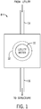
- FIG. 1 illustrates a block diagram of a utility meter system 8 that includes a utility meter 10 connected to a meter socket 12.
- the meter socket 12 includes connections to a utility supply line 14 and a load line 16. Therefore, after the utility meter 10 is inserted into the meter socket 12, electricity from the utility supply line 14 may flow through the utility meter 10 and to the load line 16.
- the load line 16 may provide electricity to a structure (e.g., a load), such as a residence or a commercial building. The amount of electricity consumed by the structure can then be measured by the utility meter 10.
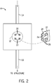
- FIG. 2 illustrates a block diagram that details how the utility meter 10 of FIG. 1 is connected to the meter socket 12 of FIG. 1 .
- the meter socket 12 may include pairs of socket jaws 20 and 22.
- the socket jaws 20, 22 may serve as clamps that secure corresponding pairs of terminals 24 and 26 of the utility meter 10 to the meter socket 12.
- the terminals 24, 26 may be disposed on a base 28 of the utility meter 12.
- the meter socket 12 may include any number of socket jaws 20, 22.
- the utility meter 10 may include any number of terminals 24, 26.
- the socket jaws 20, 22 create an electrical connection between the utility meter 10, the utility supply line 14, and the load line 16.
- a first pair of socket jaws 20 may be electrically coupled to the utility supply line 14 and a second pair of socket jaws 22 may be electrically coupled to the load line 16.
- the first pair of socket jaws 20 and the second pair of socket jaws 22 are coupled to each other via a relay, a service switch, or the electrical line.
- the terminals 24, 26 come into contact with the socket jaws 20, 22, thereby establishing an electrical connection between the utility supply line 14 and the load line 16 via the utility meter 10.
- a sufficient contact force between the socket jaws 20, 22 and the contact terminals 24, 26 should be maintained. Referring now to FIG.
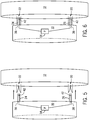
- the utility meter base 28 may include the first pair of terminals 24 and the second pair of terminals 26.
- Each terminal 24, 26 may further include a first half 30 and a second half 32.
- the first half 30 and the second half 32 may both be constructed from conductive metals such that the terminals 24, 26 may establish an electrical connection between the utility supply line 14 and the load line 16 when disposed in the socket jaws 20, 22.
- force sensing units 38 may be disposed between the first half 30 and the second half 32, as shown in FIG. 3 .
- the force sensing unit 38 may measure a force between the socket jaws 20, 22 and the terminals 24, 26 of the utility meter 10 when the terminal 24, 26 is secured between the blades of the socket jaws 20, 22.
- the force sensing units 38 may be fastened to the first half 30 of the terminals 24, 26 with an adhesive or other any other form of fastener. Alternatively, the force sensing units 38 may be fastened to the second half 32, a first blade of the socket jaws 20, 22, and/or a second blade of the socket jaws 20, 22 using an adhesive or other form of fastener. In certain embodiments the force sensing units 38 may include sensors 42. The sensors 42 may be a portion of the force sensing units 38 that measure changes in an applied force. The sensors 42 may be any size and shape and may measure a contact force between the socket jaws 20, 22 and a respective terminal 24, 26 when the terminal is secured between the blades of the socket jaws 20, 22.
- the force sensing units 38 may be piezoresistive force sensors.
- a piezoresistive force sensor experiences changes in conductance in proportion to an applied force. Therefore, as the contact force between the blades of the socket jaws 20, 22 and the terminals 24, 26 decreases, the conductance of the piezoresistive force sensor may also decrease.
- the conductance of the piezoresistive force sensor may be inversely proportional to the contact force.
- the piezoresistive force sensor may be a FlexiForce® sensor manufactured by Tekscan®.
- other types of force sensors may be utilized such as force sensing resistors, film load cells, membrane potentiometers, or any other device that measures a change in an applied force between two objects.
- FIG. 4 illustrates an exploded view of the terminal 24 of FIG. 3 with the force sensing unit 38 disposed between the two halves 30, 32.
- the force sensing unit 38 is fastened to the first half 30 of the terminal 24, however, in other embodiments, the force sensing unit 38 may be fastened to the second half 32.
- the first half 30 and the second half 32 may be coupled to one another by screws, adhesives, clamps, or any other mechanism that may couple the first half 30 to the second half 32.
- the first half 30 and the second half 32 may be substantially the same size as a standard utility meter terminal, such that the first half 30 and the second half 32 fit into a socket jaw 20, 22 of the meter socket.
- the first half 30 and the second half 32 may be coupled such that the force sensing unit 38 is not subject to an applied force between the first half 30 and the second half 32 when the terminal 24 is not secured by the socket jaws 20, 22.
- a gap may be present between the first half 30 and the second half 32 to house the force sensing unit 38, such that no force is exerted on the force sensing unit 38.
- the force sensing unit 38 may measure a clamping force when the terminal 24 is secured between the blades of the socket jaws 20, 22. The blades of the socket jaws 20, 22 may exert a force on the first half 30 and the second half 32 of the terminal 24.
- the force exerted by the blades of the socket jaws 20, 22 may close the gap between the first half 30 and the second half 32, thereby enabling the first half 30 to exert a force equal to the force exerted by the socket jaws 20, 22 on the second half 32. Therefore, the force sensing unit 38 becomes subject to the force exerted by the first half 30 on the second half 32, such that it can measure the contact force between the terminal 24 and the socket jaws 20, 22.
- no gap may form between the first half 30 and the second half 32 when the first half 30 and the second half 32 are coupled to one another.
- the force sensing unit 38 may be calibrated or normalized to measure additional force applied on the force sensing unit 38, but not the force due to the two halves 30, 32.
- FIG. 5 illustrates a side view of the utility meter 10 aligned with the socket jaws 20, 22 of the meter socket 12.
- the terminals 24, 26 of the utility meter are positioned to fit into the socket jaws 20, 22 of the meter socket 12, thereby creating an electrical connection between the utility supply line 14 and the load line 16.
- the force sensing unit 38 may be disposed on the first half 30 of the terminals 24, 26 such that the force sensing unit 38 is between the first half 30 and the second half 32 of the terminals 24, 26. Therefore, the force sensing unit 38 may be enclosed by the terminals 24, 26 such that it cannot be seen when the first half 30 is coupled to the second half 32.
- the force sensing unit 38 may be disposed on the first half 30, such that the sensor 42 is positioned substantially near a location where the blades of the socket jaws 20, 22 and the terminals 24, 26 contact each other. In other words, the sensor 42 is positioned, such that it can measure the contact force between the socket jaws 20, 22 and the terminals 24, 26.
- the force sensing unit 38 is electronically coupled to a processor 54.
- the processor may be disposed within the utility meter 10.
- the force sensing unit 38 sends a signal corresponding to a contact force value between the socket jaws 20, 22 and the terminals 24, 26 to the processor.
- the processor 54 will be described in greater detail with reference to FIGS. 7 and 8 .
- FIG. 7 and 8 The processor 54 will be described in greater detail with reference to FIGS. 7 and 8 .
- FIG. 6 illustrates a side view of the utility meter 10 secured in the socket jaws 20, 22 of the meter socket 12.
- the terminals 24, 26 of the utility meter 10 may be placed between two blades of the socket jaws 20, 22.
- the force sensing unit 38 may measure the contact force between the terminals 24, 26 and the blades of the socket jaws 20, 22.
- a utility company may remotely and continuously monitor the contact force between the socket jaws 20, 22 the terminals 24, 26 of the utility meter 10 to ensure a proper electrical connection is being maintained between the two.
- FIG. 7 illustrates a block diagram of components of the utility meter 10.
- the utility meter 10 may receive measurements or data from the force sensing unit 38 and send the measurements to the utility provider. To perform these operations, the utility meter 10 may include a communication component 52, the processor 54, a memory device 56, a storage component 58, input/output (I/O) circuitry 60, and a display component 62.
- I/O input/output
- the utility meter includes the processor 54 (e.g., a general purpose microprocessor, an application-specific integrated circuit (ASIC), or other suitable processing circuitry) that may be capable of executing instructions (e.g., executable applications, modules, routines, firmware, and so forth) to provide the desired functionality of the utility meter 50.
- the processor 54 may receive data from at least the force sensing unit 38 via the communication component 52.
- the communication component 52 may be any device capable of receiving data, whether through a wireless or wired connection.
- the data may be the contact force measurement between the socket jaws 20, 22 and the terminals 24, 26.
- the data may be a conductance signal from the force sensing unit 38 corresponding to the contact force.
- the processor 54 may perform a conversion of the conductance to a contact force value.
- the utility meter 10 has a memory device 56.
- the memory device 56 may include a volatile memory, such as random access memory (RAM), and/or a nonvolatile memory, such as ROM.
- the memory device 56 may store a variety of information and may be used for various purposes.
- the memory device 56 may store processor-executable instructions (e.g., firmware or software) for the processor 54 to execute, such as instructions for displaying an output based on the data received from the force sensing unit 38.
- the utility meter 10 may also include a storage device(s) 58 (e.g., nonvolatile storage), which may include read-only memory (ROM), flash memory, a hard drive, or any other suitable optical, magnetic, or solid-state storage medium, or a combination thereof.
- the storage device(s) 58 may store data (e.g., contact forces over time), instructions (e.g., software or firmware for displaying an output, or the like), and any other suitable data.
- the utility meter 10 may also include I/O circuitry 60 capable of receiving user input via one or more input devices (e.g., touchscreens, pointing devices, keyboards, microphones, accelerometers, and so forth) and/or providing output to the user via one or more displays 62 (e.g., touchscreens, speakers, indicator lights, printers, and so forth).
- input devices e.g., touchscreens, pointing devices, keyboards, microphones, accelerometers, and so forth
- displays 62 e.g., touchscreens, speakers, indicator lights, printers, and so forth.
- FIG. 8 illustrates a flow chart 70 for controlling an operation of the utility meter 10 based on contact force data.
- the processor 54 receives a contact force value from a clamp-force detector.
- the clamp-force detector is the force sensing unit 38, or some other device that is configured to measure the amount of force between the socket jaws 20, 22 and the terminals 24, 26 of the utility meter 10.
- the processor 54 may, in certain embodiments, generate a visualization regarding a contact-force value on a display 76. Embodiments of the display 76 will be described more fully with reference to FIGS. 9 and 10 below.
- the processor 54 may determine whether the contact force value received by the processor 54 is below a threshold value.
- the threshold value may be a force determined to be minimally sufficient for a reliable electrical connection. For example, the threshold value may be approximately 225 Newtons ("N").
- the threshold value may depend on a variety of factors, such as the material of the terminal, the material of the socket jaw blades, the amount of electric power being transferred through the utility meter, among others. Therefore, depending on the properties of the terminal and the socket jaw, the threshold value may be more or less than 225 Newtons. If the contact force value received by the processor 54 is not below the threshold value, then the processor 54 may return to block 72 and continue to receive contact force values and generate a visualization regarding the received contact force values, as described above with respect to block 72 and block 74.
- the processor 54 may proceed to block 80.
- the processor 54 may send a command to the utility meter 10 to open a circuit that connects the utility supply line 14 to the load line 16, such that electricity cannot flow from the utility supply line 14 to the load line 16.
- the utility meter 10 may include a service switch that may open and close the circuit.
- the processor 54 may send a command to change a position of the service switch from a closed circuit position to an open circuit position (e.g., via an actuator), such that electricity cannot flow from the supply line 14 to the load line 16.
- the processor 54 may, in addition to or in lieu of disconnecting a flow of electricity, generate a signal to be received by a utility company alerting the company that the contact force may be insufficient. Further, some embodiments may also display to an observer of the utility meter 10 that the contact force is insufficient through display 76, display 94, or a combination of both.
- FIG. 9 shows one embodiment of the display 76 that may generate the visualization regarding the contact force value.
- the display 76 in FIG. 9 includes two indicators 84, 86.
- the first indicator 84 may illuminate when the contact-force value is at or above a value.
- the value may be set at a point where the contact force between the socket jaws 20, 22 and the terminals 24, 26 of the utility meter 10 is sufficient to ensure that electrical current will flow through the utility meter 10 from the utility supply line 14 to the load line 16.
- the value may be the same or different from the threshold value used by the processor to determine whether or not to send the signal to change the position of the service switch. For example, the value may be approximately 225 N.
- the second indicator 86 may illuminate.
- the first indicator 84 may be a green light-emitting diode (LED).
- the second indicator 86 may be a red LED.
- the first indicator 84 and the second indicator 86 may include illumination devices of any color.
- the first indicator 84 and the second indicator 86 may have labels 88, 90 beneath them, which further signal to an observer that the contact force is either "ADEQUATE" 88 or "INADEQUATE" 90.
- FIG. 10 shows another embodiment of a display 94 of the utility meter 10.
- the display 94 may include a digital display 96 of the contact force value received from the force sensing unit 38 or other device configured to measure the force between the socket jaws 20, 22 and the terminals 24, 26 of the utility meter 10.
- the digital display 96 may have a label 98 beneath it, which clarifies to an observer what value is being displayed or measured. For example, FIG. 10 illustrates that the "CONTACT FORCE" 98 is being shown.
- the display 94 may include an analog display of the contact force or the conductance of the piezoresistive force sensor in lieu of, or in addition to, the digital display 96.
- an alternative embodiment may have a combination of both the display 76 and the display 94.
- a display may contain the first indicator 84 and the second indicator 86 as well as the digital display 96.
- the first indicator 84, the second indicator 86, the digital display 96, or a combination of the three may include the labels 88, 90, 98 beneath it.
- a separate test device may be used to test the contact force of the socket jaws 20, 22 (e.g., when the utility meter 10 is not secured in the meter socket 12 as illustrated in FIG. 5 , for example).
- the test device may include the force sensing unit 38 disposed on, or between two halves of, a member, or members.
- the member or members may be approximately the same size as the terminals 24, 26 of the utility meter 10, such that the member or members may fit between the blades of the socket jaws 20, 22 in a similar manner to the utility meter terminals 24, 26.
- the test device may be inserted between the blades of the socket jaws 20, 22 to assess the contact force that may occur if the utility meter 10 were secured in the meter socket 12.
- the force sensing unit 38 of the test device may measure a contact force between the blades of the socket jaws 20, 22 and a member, or members, of the test device.
- the test device may include more than one member such that it may measure the contact force between the blades of the socket jaws 20, 22 and the more than one members simultaneously.
- the test device may also include a processor 54 and the corresponding displays 76, 94 as discussed with the embodiments recited above.
- the test device may be utilized by a serviceman or a customer of the utility supply company to assess whether the contact force between the utility meter and the utility is adequate.
Claims (14)
- System, das zum Messen einer von einer Last verbrauchten Strommenge eingerichtet ist, umfassend:einen Verbrauchszähler (10), umfassend einen ersten Anschlussstecker (24), wobei der erste Anschlussstecker (24) eine erste Hälfte (30) und eine zweite Hälfte (32) umfasst;eine Kontaktklemme (20, 22), umfassend:einen ersten Klemmenteil; undeinen zweiten Klemmenteil, wobei der erste Klemmenteil und der zweite Klemmenteil zur Aufnahme des ersten Anschlusssteckers (24) eingerichtet sind; unddadurch gekennzeichnet, dass das System weiter umfasst:eine Kraftabtasteinheit (38), die zwischen der ersten Hälfte (30) und der zweiten Hälfte (32) des ersten Anschlusssteckers (24) angeordnet ist, wobei die Kraftabtasteinheit (38) zum kontinuierlichen Messen einer Kontaktkraft zwischen dem ersten Klemmenteil und dem ersten Anschlussstecker (24) eingerichtet ist;einen Prozessor (54), der zum Empfangen von Daten von der Kraftabtasteinheit (38) eingerichtet ist, wobei die Daten der Kontaktkraft entsprechen;eine Speichereinheit (56) und eine Speicherkomponente (58), die zum kontinuierlichen Speichern von Daten von dem Prozessor (54) eingerichtet sind; undeine Anzeige (76), die einen ersten Indikator (84) und einen zweiten Indikator (86) umfasst, und wobei der erste Indikator (84) aufleuchtet, wenn die Kontaktkraft größer oder gleich einem Schwellenwert ist, und der zweite Indikator (86) aufleuchtet, wenn die Kontaktkraft unter dem Schwellenwert liegt.
- System nach Anspruch 1, umfassend einen Serviceschalter, der dazu eingerichtet ist einen Stromfluss durch den Verbrauchszähler (10) zu unterbrechen, wenn die Kontaktkraft kleiner als der Schwellenwert ist.
- System nach Anspruch 2, wobei der Wert ungefähr 225 Newton ("N") beträgt.
- System nach Anspruch 1, wobei der Wert 225 N beträgt.
- System nach Anspruch 1, wobei der erste Indikator (84) und der zweite Indikator (86) lichtemittierende Dioden(LED)-Leuchten sind.
- System nach einem der Ansprüche 1 bis 3, wobei:die Anzeige (76) dazu eingerichtet ist, eine die Daten darstellende Visualisierung zu generieren.
- System nach einem vorhergehenden Anspruch, wobei die Kraftabtasteinheit (38) einen piezoresistiven Kraftsensor umfasst.
- System nach einem vorhergehenden Anspruch, umfassend:eine zweite Kontaktklemme (22), umfassend:einen dritten Klemmenteil; undeinen vierten Klemmenteil, wobei der dritte Klemmenteil und der vierte Klemmenteil zur Aufnahme eines zweiten Anschlusssteckers (26) des Verbrauchszählers (10) eingerichtet sind, wobei der zweite Anschlussstecker (26) eine dritte Hälfte (30) und eine vierte Hälfte (32) umfasst; undeine zweite Kraftabtasteinheit (38), die zwischen der dritten Hälfte (30) und der vierten Hälfte (32) des zweiten Anschlusssteckers (26) angeordnet ist wobei die zweite Kraftabtasteinheit (38) dazu eingerichtet ist, eine zweite Kontaktkraft zwischen der zweiten Kontaktklemme (22) und dem zweiten Anschlussstecker (26) zu messen.
- Verfahren zum Unterbrechen eines elektrischen Stromflusses durch einen Verbrauchszähler (10), umfassend:kontinuierlich Empfangen eines Kontaktkraftwerts zwischen einem ersten Klemmenteil einer Kontaktklemme (20) und einem ersten Anschlussstecker (24) des Verbrauchszählers (10) von einem Klemmkraftaufnehmer (38), wobei die Kontaktklemme (20) zur Aufnahme des Verbrauchszählers (10) eingerichtet ist;einen Prozessor (54), der zum Empfangen von Daten von dem Klemmkraftaufnehmer (38) eingerichtet ist, wobei die Daten der Kontaktkraft entsprechen;eine Speichereinheit (56) und eine Speicherkomponente (58) zum kontinuierlichen Speichern von Daten von dem Prozessor (54);Ermitteln, ob der Kontaktkraftwert unter einem Schwellenwert liegt; undSenden eines Signals zu einem Serviceschalter, wenn der Kontaktkraftwert unter dem Schwellenwert liegt, wobei der Serviceschalter dazu eingerichtet ist, den elektrischen Stromfluss zu unterbrechen, wenn das Signal von dem Serviceschalter empfangen wird.
- Verfahren nach Anspruch 9, wobei der Schwellenwert ungefähr 225 N beträgt.
- Verfahren nach Anspruch 9 oder 10, wobei der Verbrauchszähler (10) eine Anzeige (76) umfasst, welche einen ersten Indikator (84) und einen zweiten Indikator (86) umfasst, und weiter das Aufleuchtenlassen des ersten Indikators (84), wenn der Kontaktkraftwert größer oder gleich dem Schwellenwert ist, und Aufleuchtenlassen des zweiten Indikators (86), wenn der Kontaktkraftwert unter dem Schwellenwert liegt, umfassend.
- Verfahren nach Anspruch 11, wobei der erste Indikator (84) und der zweite Indikator (86) lichtemittierende Dioden(LED)-Leuchten sind.
- Verfahren nach Anspruch 11, umfassend Generieren einer die Daten darstellenden Visualisierung, Anzeigen der Visualisierung auf der Anzeige (76).
- Verfahren nach einem der Ansprüche 9 bis 13, wobei der Klemmkraftaufnehmer (38) einen piezoresistiven Kraftsensor umfasst.
Applications Claiming Priority (1)
| Application Number | Priority Date | Filing Date | Title |
|---|---|---|---|
| US14/600,413 US9714965B2 (en) | 2015-01-20 | 2015-01-20 | System for measuring contact force in a utility meter |
Publications (2)
| Publication Number | Publication Date |
|---|---|
| EP3048425A1 EP3048425A1 (de) | 2016-07-27 |
| EP3048425B1 true EP3048425B1 (de) | 2017-12-27 |
Family
ID=55177802
Family Applications (1)
| Application Number | Title | Priority Date | Filing Date |
|---|---|---|---|
| EP16151753.7A Active EP3048425B1 (de) | 2015-01-20 | 2016-01-18 | System zur messung der kontaktkraft in einem verbrauchszähler |
Country Status (8)
| Country | Link |
|---|---|
| US (1) | US9714965B2 (de) |
| EP (1) | EP3048425B1 (de) |
| JP (1) | JP6691779B2 (de) |
| CN (1) | CN105807154B (de) |
| BR (1) | BR102016001181B1 (de) |
| CA (1) | CA2917570C (de) |
| ES (1) | ES2664356T3 (de) |
| MX (1) | MX352743B (de) |
Families Citing this family (6)
| Publication number | Priority date | Publication date | Assignee | Title |
|---|---|---|---|---|
| CH711008A1 (de) * | 2015-04-30 | 2016-10-31 | Kistler Holding Ag | Kontaktkraft-Prüfvorrichtung, Verwendung einer solchen Kontaktkraft-Prüfvorrichtung und Verfahren zur Herstellung einer solchen Kontaktkraft-Prüfvorrichtung. |
| WO2020236656A1 (en) | 2019-05-17 | 2020-11-26 | Aclara Technologies Llc | Service switch for utility meter |
| EP3757536A1 (de) * | 2019-06-25 | 2020-12-30 | Kistler Holding AG | Kontaktkraftmessvorrichtung und verfahren zum messen einer kontaktkraft mit einer solchen kontaktkraftmessvorrichtung |
| US11688923B2 (en) | 2020-12-04 | 2023-06-27 | Honeywell International Inc. | LTE antenna optimized for North American electricity meters |
| CN113064111B (zh) * | 2021-03-23 | 2022-07-15 | 广东电网有限责任公司计量中心 | 一种智能电能表推拉力测试装置 |
| US11860194B2 (en) | 2021-05-13 | 2024-01-02 | Honeywell International Inc. | Socket-jaw protection module for a meter |
Family Cites Families (11)
| Publication number | Priority date | Publication date | Assignee | Title |
|---|---|---|---|---|
| US3388590A (en) | 1965-11-29 | 1968-06-18 | Hugh L. Dryden | Connector internal force gauge |
| DE4003552C2 (de) | 1990-02-06 | 1996-02-29 | Grote & Hartmann | Verfahren und Vorrichtung zur Kontaktkraftmessung |
| US5024106A (en) * | 1990-03-13 | 1991-06-18 | Amp Incorporated | Contact system normal force gage |
| US5334057A (en) * | 1993-02-19 | 1994-08-02 | Blackwell Larry R | Connectors for electrical meter socket adapters |
| US6766698B1 (en) | 2002-06-03 | 2004-07-27 | Ekstrom Industries, Inc. | Meter socket jaw tester apparatus and test method |
| JP4527515B2 (ja) * | 2004-12-15 | 2010-08-18 | 関西電力株式会社 | ユニット型電力量計 |
| JP2007149517A (ja) * | 2005-11-29 | 2007-06-14 | Sadao Mizukami | 端子接触圧測定方法およびその測定具 |
| US7683642B2 (en) | 2006-09-28 | 2010-03-23 | Landis+Gyr, Inc. | Apparatus and method for metering contact integrity |
| DE102010008755A1 (de) * | 2010-02-17 | 2011-08-18 | E.G.O. Elektro-Gerätebau GmbH, 75038 | Verfahren und Vorrichtung zum Ausschalten eines Schalters |
| JP5443257B2 (ja) * | 2010-04-30 | 2014-03-19 | 株式会社明電舎 | 接触力測定方法及び接触力測定装置 |
| CN202255725U (zh) * | 2011-09-19 | 2012-05-30 | 厦门跨世机械制造有限公司 | 一种插座金属弹片的力值测量装置 |
-
2015
- 2015-01-20 US US14/600,413 patent/US9714965B2/en active Active
-
2016
- 2016-01-14 CA CA2917570A patent/CA2917570C/en active Active
- 2016-01-14 JP JP2016004884A patent/JP6691779B2/ja active Active
- 2016-01-18 ES ES16151753.7T patent/ES2664356T3/es active Active
- 2016-01-18 EP EP16151753.7A patent/EP3048425B1/de active Active
- 2016-01-19 BR BR102016001181-7A patent/BR102016001181B1/pt active IP Right Grant
- 2016-01-19 MX MX2016000781A patent/MX352743B/es active IP Right Grant
- 2016-01-20 CN CN201610036801.2A patent/CN105807154B/zh active Active
Non-Patent Citations (1)
| Title |
|---|
| None * |
Also Published As
| Publication number | Publication date |
|---|---|
| BR102016001181B1 (pt) | 2022-04-19 |
| CN105807154A (zh) | 2016-07-27 |
| MX2016000781A (es) | 2016-08-12 |
| ES2664356T3 (es) | 2018-04-19 |
| BR102016001181A2 (pt) | 2016-08-02 |
| US20160209464A1 (en) | 2016-07-21 |
| CN105807154B (zh) | 2019-07-30 |
| CA2917570A1 (en) | 2016-07-20 |
| JP2016176921A (ja) | 2016-10-06 |
| EP3048425A1 (de) | 2016-07-27 |
| JP6691779B2 (ja) | 2020-05-13 |
| CA2917570C (en) | 2023-09-05 |
| MX352743B (es) | 2017-12-06 |
| US9714965B2 (en) | 2017-07-25 |
Similar Documents
| Publication | Publication Date | Title |
|---|---|---|
| EP3048425B1 (de) | System zur messung der kontaktkraft in einem verbrauchszähler | |
| KR101670785B1 (ko) | 각속도센서 점검장치 | |
| EP2081039B1 (de) | Abschaltbarer Batteriezustandsalarm und Batteriedetektor dafür | |
| US8344737B2 (en) | Relay circuit tester device | |
| JP6549550B2 (ja) | 電気システムにおける配電を監視する電力監視プローブ | |
| CN104122420A (zh) | 带有可交换范围和灵敏度设置模块的示波器电流探针 | |
| JP2016176921A5 (de) | ||
| WO2009024444A3 (de) | Überwachungsvorrichtung zur überwachung eines anschlusses einer anschlusskomponente | |
| JP2009222400A (ja) | センサシステム | |
| US20110167919A1 (en) | Vacuum measuring device with interchangeable sensors | |
| CN106053911A (zh) | 简易万用表 | |
| CN104054222A (zh) | 电连接器 | |
| CN104006868B (zh) | 智能模拟式称重传感器及其自诊断方法 | |
| CN102812338A (zh) | 用于电子秤的零点设置方法及装置 | |
| EP2284559A3 (de) | Elektrische Ausrüstungsanordnung und Verfahren zur Kalibrierung der elektrischen Ausrüstungsanordnung | |
| CN205426187U (zh) | 过程变量测量和具有多个范围的本地显示 | |
| TWI505530B (zh) | 電池容量檢測系統 | |
| KR200360131Y1 (ko) | 복수 모듈형 전자식 전력량계 | |
| CN203191123U (zh) | 数字显示继电器测力计 | |
| US20170097249A1 (en) | Sensor and cable with local wireless read and write capability and methods of using same | |
| CN201811817U (zh) | 一种压力表 | |
| EP2926360A1 (de) | Sicherungshaltevorrichtung | |
| KR101474740B1 (ko) | 인쇄회로기판용 pc 카드 테스트기 | |
| US9983252B2 (en) | Systems and methods for testing resistance based on customer specific wires | |
| CN103105543A (zh) | 一种用于监控gpu插座磨损的电路和方法 |
Legal Events
| Date | Code | Title | Description |
|---|---|---|---|
| PUAI | Public reference made under article 153(3) epc to a published international application that has entered the european phase |
Free format text: ORIGINAL CODE: 0009012 |
|
| AK | Designated contracting states |
Kind code of ref document: A1 Designated state(s): AL AT BE BG CH CY CZ DE DK EE ES FI FR GB GR HR HU IE IS IT LI LT LU LV MC MK MT NL NO PL PT RO RS SE SI SK SM TR |
|
| AX | Request for extension of the european patent |
Extension state: BA ME |
|
| RAP1 | Party data changed (applicant data changed or rights of an application transferred) |
Owner name: ACLARA METERS LLC |
|
| 17P | Request for examination filed |
Effective date: 20170125 |
|
| RBV | Designated contracting states (corrected) |
Designated state(s): AL AT BE BG CH CY CZ DE DK EE ES FI FR GB GR HR HU IE IS IT LI LT LU LV MC MK MT NL NO PL PT RO RS SE SI SK SM TR |
|
| GRAP | Despatch of communication of intention to grant a patent |
Free format text: ORIGINAL CODE: EPIDOSNIGR1 |
|
| INTG | Intention to grant announced |
Effective date: 20170717 |
|
| GRAA | (expected) grant |
Free format text: ORIGINAL CODE: 0009210 |
|
| GRAS | Grant fee paid |
Free format text: ORIGINAL CODE: EPIDOSNIGR3 |
|
| AK | Designated contracting states |
Kind code of ref document: B1 Designated state(s): AL AT BE BG CH CY CZ DE DK EE ES FI FR GB GR HR HU IE IS IT LI LT LU LV MC MK MT NL NO PL PT RO RS SE SI SK SM TR |
|
| REG | Reference to a national code |
Ref country code: GB Ref legal event code: FG4D |
|
| REG | Reference to a national code |
Ref country code: CH Ref legal event code: EP |
|
| REG | Reference to a national code |
Ref country code: AT Ref legal event code: REF Ref document number: 958686 Country of ref document: AT Kind code of ref document: T Effective date: 20180115 |
|
| REG | Reference to a national code |
Ref country code: IE Ref legal event code: FG4D |
|
| REG | Reference to a national code |
Ref country code: DE Ref legal event code: R096 Ref document number: 602016001163 Country of ref document: DE |
|
| RAP2 | Party data changed (patent owner data changed or rights of a patent transferred) |
Owner name: ACLARA METERS LLC |
|
| REG | Reference to a national code |
Ref country code: ES Ref legal event code: FG2A Ref document number: 2664356 Country of ref document: ES Kind code of ref document: T3 Effective date: 20180419 |
|
| PG25 | Lapsed in a contracting state [announced via postgrant information from national office to epo] |
Ref country code: LT Free format text: LAPSE BECAUSE OF FAILURE TO SUBMIT A TRANSLATION OF THE DESCRIPTION OR TO PAY THE FEE WITHIN THE PRESCRIBED TIME-LIMIT Effective date: 20171227 Ref country code: NO Free format text: LAPSE BECAUSE OF FAILURE TO SUBMIT A TRANSLATION OF THE DESCRIPTION OR TO PAY THE FEE WITHIN THE PRESCRIBED TIME-LIMIT Effective date: 20180327 Ref country code: FI Free format text: LAPSE BECAUSE OF FAILURE TO SUBMIT A TRANSLATION OF THE DESCRIPTION OR TO PAY THE FEE WITHIN THE PRESCRIBED TIME-LIMIT Effective date: 20171227 |
|
| PGFP | Annual fee paid to national office [announced via postgrant information from national office to epo] |
Ref country code: ES Payment date: 20180326 Year of fee payment: 3 |
|
| REG | Reference to a national code |
Ref country code: NL Ref legal event code: MP Effective date: 20171227 |
|
| REG | Reference to a national code |
Ref country code: LT Ref legal event code: MG4D |
|
| REG | Reference to a national code |
Ref country code: AT Ref legal event code: MK05 Ref document number: 958686 Country of ref document: AT Kind code of ref document: T Effective date: 20171227 |
|
| PG25 | Lapsed in a contracting state [announced via postgrant information from national office to epo] |
Ref country code: LV Free format text: LAPSE BECAUSE OF FAILURE TO SUBMIT A TRANSLATION OF THE DESCRIPTION OR TO PAY THE FEE WITHIN THE PRESCRIBED TIME-LIMIT Effective date: 20171227 Ref country code: HR Free format text: LAPSE BECAUSE OF FAILURE TO SUBMIT A TRANSLATION OF THE DESCRIPTION OR TO PAY THE FEE WITHIN THE PRESCRIBED TIME-LIMIT Effective date: 20171227 Ref country code: RS Free format text: LAPSE BECAUSE OF FAILURE TO SUBMIT A TRANSLATION OF THE DESCRIPTION OR TO PAY THE FEE WITHIN THE PRESCRIBED TIME-LIMIT Effective date: 20171227 Ref country code: BG Free format text: LAPSE BECAUSE OF FAILURE TO SUBMIT A TRANSLATION OF THE DESCRIPTION OR TO PAY THE FEE WITHIN THE PRESCRIBED TIME-LIMIT Effective date: 20180327 |
|
| PGFP | Annual fee paid to national office [announced via postgrant information from national office to epo] |
Ref country code: BE Payment date: 20180205 Year of fee payment: 3 |
|
| PG25 | Lapsed in a contracting state [announced via postgrant information from national office to epo] |
Ref country code: NL Free format text: LAPSE BECAUSE OF FAILURE TO SUBMIT A TRANSLATION OF THE DESCRIPTION OR TO PAY THE FEE WITHIN THE PRESCRIBED TIME-LIMIT Effective date: 20171227 |
|
| PG25 | Lapsed in a contracting state [announced via postgrant information from national office to epo] |
Ref country code: EE Free format text: LAPSE BECAUSE OF FAILURE TO SUBMIT A TRANSLATION OF THE DESCRIPTION OR TO PAY THE FEE WITHIN THE PRESCRIBED TIME-LIMIT Effective date: 20171227 Ref country code: CY Free format text: LAPSE BECAUSE OF FAILURE TO SUBMIT A TRANSLATION OF THE DESCRIPTION OR TO PAY THE FEE WITHIN THE PRESCRIBED TIME-LIMIT Effective date: 20171227 Ref country code: CZ Free format text: LAPSE BECAUSE OF FAILURE TO SUBMIT A TRANSLATION OF THE DESCRIPTION OR TO PAY THE FEE WITHIN THE PRESCRIBED TIME-LIMIT Effective date: 20171227 Ref country code: SK Free format text: LAPSE BECAUSE OF FAILURE TO SUBMIT A TRANSLATION OF THE DESCRIPTION OR TO PAY THE FEE WITHIN THE PRESCRIBED TIME-LIMIT Effective date: 20171227 |
|
| REG | Reference to a national code |
Ref country code: DE Ref legal event code: R119 Ref document number: 602016001163 Country of ref document: DE |
|
| PG25 | Lapsed in a contracting state [announced via postgrant information from national office to epo] |
Ref country code: AT Free format text: LAPSE BECAUSE OF FAILURE TO SUBMIT A TRANSLATION OF THE DESCRIPTION OR TO PAY THE FEE WITHIN THE PRESCRIBED TIME-LIMIT Effective date: 20171227 Ref country code: SM Free format text: LAPSE BECAUSE OF FAILURE TO SUBMIT A TRANSLATION OF THE DESCRIPTION OR TO PAY THE FEE WITHIN THE PRESCRIBED TIME-LIMIT Effective date: 20171227 Ref country code: IT Free format text: LAPSE BECAUSE OF FAILURE TO SUBMIT A TRANSLATION OF THE DESCRIPTION OR TO PAY THE FEE WITHIN THE PRESCRIBED TIME-LIMIT Effective date: 20171227 Ref country code: IS Free format text: LAPSE BECAUSE OF FAILURE TO SUBMIT A TRANSLATION OF THE DESCRIPTION OR TO PAY THE FEE WITHIN THE PRESCRIBED TIME-LIMIT Effective date: 20180427 Ref country code: RO Free format text: LAPSE BECAUSE OF FAILURE TO SUBMIT A TRANSLATION OF THE DESCRIPTION OR TO PAY THE FEE WITHIN THE PRESCRIBED TIME-LIMIT Effective date: 20171227 Ref country code: PL Free format text: LAPSE BECAUSE OF FAILURE TO SUBMIT A TRANSLATION OF THE DESCRIPTION OR TO PAY THE FEE WITHIN THE PRESCRIBED TIME-LIMIT Effective date: 20171227 |
|
| PG25 | Lapsed in a contracting state [announced via postgrant information from national office to epo] |
Ref country code: MC Free format text: LAPSE BECAUSE OF FAILURE TO SUBMIT A TRANSLATION OF THE DESCRIPTION OR TO PAY THE FEE WITHIN THE PRESCRIBED TIME-LIMIT Effective date: 20171227 |
|
| PG25 | Lapsed in a contracting state [announced via postgrant information from national office to epo] |
Ref country code: LU Free format text: LAPSE BECAUSE OF NON-PAYMENT OF DUE FEES Effective date: 20180118 Ref country code: FR Free format text: LAPSE BECAUSE OF NON-PAYMENT OF DUE FEES Effective date: 20180227 Ref country code: DE Free format text: LAPSE BECAUSE OF NON-PAYMENT OF DUE FEES Effective date: 20180801 |
|
| REG | Reference to a national code |
Ref country code: IE Ref legal event code: MM4A |
|
| PLBE | No opposition filed within time limit |
Free format text: ORIGINAL CODE: 0009261 |
|
| REG | Reference to a national code |
Ref country code: FR Ref legal event code: ST Effective date: 20180928 |
|
| STAA | Information on the status of an ep patent application or granted ep patent |
Free format text: STATUS: NO OPPOSITION FILED WITHIN TIME LIMIT |
|
| PG25 | Lapsed in a contracting state [announced via postgrant information from national office to epo] |
Ref country code: DK Free format text: LAPSE BECAUSE OF FAILURE TO SUBMIT A TRANSLATION OF THE DESCRIPTION OR TO PAY THE FEE WITHIN THE PRESCRIBED TIME-LIMIT Effective date: 20171227 |
|
| 26N | No opposition filed |
Effective date: 20180928 |
|
| PG25 | Lapsed in a contracting state [announced via postgrant information from national office to epo] |
Ref country code: IE Free format text: LAPSE BECAUSE OF NON-PAYMENT OF DUE FEES Effective date: 20180118 |
|
| PG25 | Lapsed in a contracting state [announced via postgrant information from national office to epo] |
Ref country code: SI Free format text: LAPSE BECAUSE OF FAILURE TO SUBMIT A TRANSLATION OF THE DESCRIPTION OR TO PAY THE FEE WITHIN THE PRESCRIBED TIME-LIMIT Effective date: 20171227 |
|
| REG | Reference to a national code |
Ref country code: CH Ref legal event code: PL |
|
| REG | Reference to a national code |
Ref country code: BE Ref legal event code: MM Effective date: 20190131 |
|
| PG25 | Lapsed in a contracting state [announced via postgrant information from national office to epo] |
Ref country code: BE Free format text: LAPSE BECAUSE OF NON-PAYMENT OF DUE FEES Effective date: 20190131 |
|
| PG25 | Lapsed in a contracting state [announced via postgrant information from national office to epo] |
Ref country code: LI Free format text: LAPSE BECAUSE OF NON-PAYMENT OF DUE FEES Effective date: 20190131 Ref country code: CH Free format text: LAPSE BECAUSE OF NON-PAYMENT OF DUE FEES Effective date: 20190131 |
|
| PG25 | Lapsed in a contracting state [announced via postgrant information from national office to epo] |
Ref country code: MT Free format text: LAPSE BECAUSE OF NON-PAYMENT OF DUE FEES Effective date: 20180118 |
|
| REG | Reference to a national code |
Ref country code: ES Ref legal event code: FD2A Effective date: 20200309 |
|
| PG25 | Lapsed in a contracting state [announced via postgrant information from national office to epo] |
Ref country code: TR Free format text: LAPSE BECAUSE OF FAILURE TO SUBMIT A TRANSLATION OF THE DESCRIPTION OR TO PAY THE FEE WITHIN THE PRESCRIBED TIME-LIMIT Effective date: 20171227 |
|
| PG25 | Lapsed in a contracting state [announced via postgrant information from national office to epo] |
Ref country code: ES Free format text: LAPSE BECAUSE OF NON-PAYMENT OF DUE FEES Effective date: 20190119 |
|
| PG25 | Lapsed in a contracting state [announced via postgrant information from national office to epo] |
Ref country code: PT Free format text: LAPSE BECAUSE OF FAILURE TO SUBMIT A TRANSLATION OF THE DESCRIPTION OR TO PAY THE FEE WITHIN THE PRESCRIBED TIME-LIMIT Effective date: 20171227 |
|
| PG25 | Lapsed in a contracting state [announced via postgrant information from national office to epo] |
Ref country code: GR Free format text: LAPSE BECAUSE OF FAILURE TO SUBMIT A TRANSLATION OF THE DESCRIPTION OR TO PAY THE FEE WITHIN THE PRESCRIBED TIME-LIMIT Effective date: 20171227 Ref country code: HU Free format text: LAPSE BECAUSE OF FAILURE TO SUBMIT A TRANSLATION OF THE DESCRIPTION OR TO PAY THE FEE WITHIN THE PRESCRIBED TIME-LIMIT; INVALID AB INITIO Effective date: 20160118 Ref country code: SE Free format text: LAPSE BECAUSE OF FAILURE TO SUBMIT A TRANSLATION OF THE DESCRIPTION OR TO PAY THE FEE WITHIN THE PRESCRIBED TIME-LIMIT Effective date: 20171227 Ref country code: MK Free format text: LAPSE BECAUSE OF NON-PAYMENT OF DUE FEES Effective date: 20171227 |
|
| PG25 | Lapsed in a contracting state [announced via postgrant information from national office to epo] |
Ref country code: AL Free format text: LAPSE BECAUSE OF FAILURE TO SUBMIT A TRANSLATION OF THE DESCRIPTION OR TO PAY THE FEE WITHIN THE PRESCRIBED TIME-LIMIT Effective date: 20171227 |
|
| P01 | Opt-out of the competence of the unified patent court (upc) registered |
Effective date: 20230608 |
|
| PGFP | Annual fee paid to national office [announced via postgrant information from national office to epo] |
Ref country code: GB Payment date: 20231130 Year of fee payment: 9 |