EP3047810B1 - Growing rods and methods of use - Google Patents
Growing rods and methods of use Download PDFInfo
- Publication number
- EP3047810B1 EP3047810B1 EP16151087.0A EP16151087A EP3047810B1 EP 3047810 B1 EP3047810 B1 EP 3047810B1 EP 16151087 A EP16151087 A EP 16151087A EP 3047810 B1 EP3047810 B1 EP 3047810B1
- Authority
- EP
- European Patent Office
- Prior art keywords
- rod
- rod portion
- spinal
- locking mechanism
- injection port
- Prior art date
- Legal status (The legal status is an assumption and is not a legal conclusion. Google has not performed a legal analysis and makes no representation as to the accuracy of the status listed.)
- Active
Links
Images




Classifications
-
- A—HUMAN NECESSITIES
- A61—MEDICAL OR VETERINARY SCIENCE; HYGIENE
- A61B—DIAGNOSIS; SURGERY; IDENTIFICATION
- A61B17/00—Surgical instruments, devices or methods
- A61B17/56—Surgical instruments or methods for treatment of bones or joints; Devices specially adapted therefor
- A61B17/58—Surgical instruments or methods for treatment of bones or joints; Devices specially adapted therefor for osteosynthesis, e.g. bone plates, screws or setting implements
- A61B17/68—Internal fixation devices, including fasteners and spinal fixators, even if a part thereof projects from the skin
- A61B17/70—Spinal positioners or stabilisers, e.g. stabilisers comprising fluid filler in an implant
- A61B17/7001—Screws or hooks combined with longitudinal elements which do not contact vertebrae
- A61B17/7002—Longitudinal elements, e.g. rods
- A61B17/7011—Longitudinal element being non-straight, e.g. curved, angled or branched
-
- A—HUMAN NECESSITIES
- A61—MEDICAL OR VETERINARY SCIENCE; HYGIENE
- A61B—DIAGNOSIS; SURGERY; IDENTIFICATION
- A61B17/00—Surgical instruments, devices or methods
- A61B17/56—Surgical instruments or methods for treatment of bones or joints; Devices specially adapted therefor
- A61B17/58—Surgical instruments or methods for treatment of bones or joints; Devices specially adapted therefor for osteosynthesis, e.g. bone plates, screws or setting implements
- A61B17/68—Internal fixation devices, including fasteners and spinal fixators, even if a part thereof projects from the skin
- A61B17/70—Spinal positioners or stabilisers, e.g. stabilisers comprising fluid filler in an implant
- A61B17/7001—Screws or hooks combined with longitudinal elements which do not contact vertebrae
- A61B17/7002—Longitudinal elements, e.g. rods
-
- A—HUMAN NECESSITIES
- A61—MEDICAL OR VETERINARY SCIENCE; HYGIENE
- A61B—DIAGNOSIS; SURGERY; IDENTIFICATION
- A61B17/00—Surgical instruments, devices or methods
- A61B17/56—Surgical instruments or methods for treatment of bones or joints; Devices specially adapted therefor
- A61B17/58—Surgical instruments or methods for treatment of bones or joints; Devices specially adapted therefor for osteosynthesis, e.g. bone plates, screws or setting implements
- A61B17/68—Internal fixation devices, including fasteners and spinal fixators, even if a part thereof projects from the skin
- A61B17/70—Spinal positioners or stabilisers, e.g. stabilisers comprising fluid filler in an implant
- A61B17/7001—Screws or hooks combined with longitudinal elements which do not contact vertebrae
- A61B17/7002—Longitudinal elements, e.g. rods
- A61B17/7004—Longitudinal elements, e.g. rods with a cross-section which varies along its length
-
- A—HUMAN NECESSITIES
- A61—MEDICAL OR VETERINARY SCIENCE; HYGIENE
- A61B—DIAGNOSIS; SURGERY; IDENTIFICATION
- A61B17/00—Surgical instruments, devices or methods
- A61B17/56—Surgical instruments or methods for treatment of bones or joints; Devices specially adapted therefor
- A61B17/58—Surgical instruments or methods for treatment of bones or joints; Devices specially adapted therefor for osteosynthesis, e.g. bone plates, screws or setting implements
- A61B17/68—Internal fixation devices, including fasteners and spinal fixators, even if a part thereof projects from the skin
- A61B17/70—Spinal positioners or stabilisers, e.g. stabilisers comprising fluid filler in an implant
- A61B17/7001—Screws or hooks combined with longitudinal elements which do not contact vertebrae
- A61B17/7002—Longitudinal elements, e.g. rods
- A61B17/7014—Longitudinal elements, e.g. rods with means for adjusting the distance between two screws or hooks
-
- A—HUMAN NECESSITIES
- A61—MEDICAL OR VETERINARY SCIENCE; HYGIENE
- A61B—DIAGNOSIS; SURGERY; IDENTIFICATION
- A61B17/00—Surgical instruments, devices or methods
- A61B17/56—Surgical instruments or methods for treatment of bones or joints; Devices specially adapted therefor
- A61B17/58—Surgical instruments or methods for treatment of bones or joints; Devices specially adapted therefor for osteosynthesis, e.g. bone plates, screws or setting implements
- A61B17/68—Internal fixation devices, including fasteners and spinal fixators, even if a part thereof projects from the skin
- A61B17/70—Spinal positioners or stabilisers, e.g. stabilisers comprising fluid filler in an implant
- A61B17/7001—Screws or hooks combined with longitudinal elements which do not contact vertebrae
- A61B17/7002—Longitudinal elements, e.g. rods
- A61B17/7014—Longitudinal elements, e.g. rods with means for adjusting the distance between two screws or hooks
- A61B17/7016—Longitudinal elements, e.g. rods with means for adjusting the distance between two screws or hooks electric or electromagnetic means
-
- A—HUMAN NECESSITIES
- A61—MEDICAL OR VETERINARY SCIENCE; HYGIENE
- A61B—DIAGNOSIS; SURGERY; IDENTIFICATION
- A61B17/00—Surgical instruments, devices or methods
- A61B17/56—Surgical instruments or methods for treatment of bones or joints; Devices specially adapted therefor
- A61B17/58—Surgical instruments or methods for treatment of bones or joints; Devices specially adapted therefor for osteosynthesis, e.g. bone plates, screws or setting implements
- A61B17/68—Internal fixation devices, including fasteners and spinal fixators, even if a part thereof projects from the skin
- A61B17/70—Spinal positioners or stabilisers, e.g. stabilisers comprising fluid filler in an implant
- A61B17/7001—Screws or hooks combined with longitudinal elements which do not contact vertebrae
- A61B17/7002—Longitudinal elements, e.g. rods
- A61B17/7014—Longitudinal elements, e.g. rods with means for adjusting the distance between two screws or hooks
- A61B17/7017—Longitudinal elements, e.g. rods with means for adjusting the distance between two screws or hooks pneumatic or hydraulic means
-
- A—HUMAN NECESSITIES
- A61—MEDICAL OR VETERINARY SCIENCE; HYGIENE
- A61B—DIAGNOSIS; SURGERY; IDENTIFICATION
- A61B17/00—Surgical instruments, devices or methods
- A61B2017/00017—Electrical control of surgical instruments
- A61B2017/00221—Electrical control of surgical instruments with wireless transmission of data, e.g. by infrared radiation or radiowaves
-
- A—HUMAN NECESSITIES
- A61—MEDICAL OR VETERINARY SCIENCE; HYGIENE
- A61B—DIAGNOSIS; SURGERY; IDENTIFICATION
- A61B17/00—Surgical instruments, devices or methods
- A61B2017/00535—Surgical instruments, devices or methods pneumatically or hydraulically operated
- A61B2017/00539—Surgical instruments, devices or methods pneumatically or hydraulically operated hydraulically
Definitions
- the present invention(s) relates to spinal rods capable of expansion for treating a variety of spinal maladies.
- a scoliotic spine is one in which the spinal column is abnormally curved in one or more different directions, causing resultant adverse side effects for the person suffering from the deformity. Surgeons have attempted to correct this abnormal curvature, in some cases, with spinal rods implanted on the patient's spinal column. The spinal rods exert a force on the spinal column to correct and restore the natural curvature thereof.
- Pediatric scoliosis is a particular spinal deformity that is marred with a common issue - the patient is young and growing and, consequently, the patient's spinal column is growing as well. Thus, any effort to straighten the young patient's spinal column with, for example, a fixed-length rod is likely to encounter a problem. Namely, as the spine grows the fixed-length rod does not allow further thoracic growth in the patient. As a result, expandable spinal rods have developed to accommodate the growing spine in pediatric patients.
- Examples of existing expandable spinal rods include magnetic growing spinal rods and mechanically distractible spinal rods.
- some include a motor actuated by an external magnet to cause separate rod portions to distract and, consequently, lengthen the overall spinal rod.
- Mechanically distractible spinal rods typically have rod portions that are manually movable relative to each other via a distraction instrument. The rod portions are distracted during multiple different surgeries to cause lengthening of the overall spinal rod and correction of the underlying deformity.
- Magnetic growing rods suffer from a number of defects, however, namely distraction forces are limited by the strength of the motor used therewith.
- the overall rod is not susceptible to common medical imaging techniques (e.g., magnetic resonance imaging (MRI)) used during surgery.
- MRI magnetic resonance imaging
- Mechanically-distractible rods also suffer downsides, for example multiple invasive surgical interventions are required after the initial, primary surgery to lengthen the rod (e.g., by use of a distractor instrument). The patient therefore suffers from the side effects of multiple invasive surgeries to correct the spinal deformity.
- a first aspect of the invention includes a spinal rod.
- the rod comprises a first rod portion having an elongate rod section adapted for connection with a first fixation element implanted in a first vertebra, the first rod portion including an internal hollow cavity defined by an internal wall surface, and a second rod portion having an elongate rod section adapted for connection with a second fixation element implanted in a second vertebra, wherein the second rod portion is inserted within the internal cavity of the first rod portion and is axially movable relative to the first rod portion within the internal cavity in an expansion direction.
- the rod is sealingly engaged to the internal wall surface and thereby defines a hydraulic pressure chamber, the hydraulic pressure chamber being fluidly sealed off from the internal hollow cavity.
- the spinal rod includes an injection port and a flow channel in fluid communication with the hydraulic pressure chamber, as well as a locking mechanism engageable with the second rod portion, the locking mechanism being effective to lock the second rod portion relative to the first rod portion, wherein the locking mechanism includes a release mechanism allowing for disengagement between the locking mechanism and the second rod portion to permit movement of the second rod portion in a contraction direction opposite the expansion direction.
- the elongate rod section of the first rod portion is fixed relative to its internal hollow cavity.
- the injection port and the locking mechanism are in close proximity to each other.
- a second aspect of the invention includes a spinal rod.
- the rod comprises a first rod portion having an elongate rod section adapted for connection with a first fixation element implanted in a first vertebra, the first rod portion including an internal hollow cavity defined by an internal wall surface, and a second rod portion having an elongate rod section adapted for connection with a second fixation element implanted in a second vertebra, wherein the second rod portion is inserted within the internal cavity of the first rod portion and is axially movable relative to the first rod portion within the internal cavity in an expansion direction.
- the rod is sealingly engaged to the internal wall surface and thereby defines a hydraulic pressure chamber, the hydraulic pressure chamber being fluidly sealed off from the internal hollow cavity.
- the spinal rod includes an injection port and a flow channel in fluid communication with the hydraulic pressure chamber, as well as a locking mechanism engageable with the second rod portion, the locking mechanism being effective to lock the second rod portion relative to the first rod portion, wherein the injection port and the locking mechanism are in close proximity to each other.
- the injection port and the locking mechanism are adjacent each other on a same side of the first rod portion. Further, the injection port and the locking mechanism may be spaced apart by anywhere from between about 5 mm to about 9 mm.
- the locking mechanism is a set screw operable to bear on the second rod portion and lock it relative to the first rod portion, or it is a ratchet and pawl mechanism operable to lock the first rod portion relative to the second rod portion.
- a third aspect of the invention includes a method of operating a spinal rod.
- the method comprises engaging an elongate rod section of a first rod portion of a spinal rod with a first fixation element implanted in a first vertebra of a spine, the first rod portion including an internal hollow cavity defined by an internal wall surface, and engaging an elongate rod section of a second rod portion of the spinal rod with a second fixation element implanted in a second vertebra of the spine, the second rod portion being inserted within the internal cavity of the first rod portion and sealingly engaging the internal wall surface to thereby define a hydraulic pressure chamber.
- the method also comprises introducing hydraulic fluid into the hydraulic pressure chamber through an injection port of the spinal rod so that the hydraulic fluid acts on the second rod portion and causes it to move in an expansion direction within the internal cavity. Further, the second rod portion is locked relative to the first rod portion after the introducing step. Optionally, the hydraulic fluid is subsequently withdrawn out of the hydraulic pressure chamber.
- the small incision is anywhere from between about 4 mm to about 5 mm in length.
- the hydraulic pressure chamber is a remote distance from the injection port, and the method further comprises causing the hydraulic fluid to pass through the injection port, into a flow channel extending between the injection port and the hydraulic pressure chamber, and subsequently into the hydraulic pressure chamber, the flow channel extending substantially parallel to the internal cavity along at least a part of its length.
- a spinal column 10 is shown with multiple hydraulic rods 20 implanted thereon.
- each rod 20 is connected at both ends to one or more pedicle screw devices 12 implanted in respective vertebra of spinal column 10.
- Pedicle screw devices 12 may be any screw construct commonly known in the art including, for example, pedicle screw constructs that utilize a head with an open channel (referred to as a tulip) for accommodating a portion of a rod, and a threaded screw shank for insertion into a vertebra of spinal column 10.
- spinal hooks or other common suitable fixation devices may be used in place of pedicle screws 12, as would be recognized by one of skill in the art.
- each hydraulic spinal rod 20 may be attached to pedicle screws 12 and expanded at will.
- Rods 20 may use hydraulic technology to achieve expansion, as described in more detail below.
- rods 20 allow for expansion at selected intervals after initial implantation to accommodate changing surgical parameters (e.g., the growing spine of a pediatric patient suffering from scoliosis).
- spinal rod 20 includes multiple rod portions, namely a static rod 22 and a piston rod 60.
- Both static and piston rods 22, 60 may be straight ( Fig. 2A ), pre-bent ( Fig. 2B ) to accommodate the curvature of the spine 10 of a particular patient, or may be designed to be bent during surgery (transition from Fig. 2A to 2B ) to accommodate a particular amount of spinal curvature.
- Fig. 2A straight
- Fig. 2B pre-bent
- spinal rod 20 includes multiple rod portions, namely a static rod 22 and a piston rod 60.
- Both static and piston rods 22, 60 may be straight ( Fig. 2A ), pre-bent ( Fig. 2B ) to accommodate the curvature of the spine 10 of a particular patient, or may be designed to be bent during surgery (transition from Fig. 2A to 2B ) to accommodate a particular amount of spinal curvature.
- an end section of static rod 22 may be curved upwards (e.g., for fixation to the lumbar spine exhibiting a lordotic curvature) while an end section of piston rod 60 may be curved downwards (e.g., for fixation to the thoracic spine exhibiting a kyphotic curvature).
- static and piston rods 22, 60 may be bent in any direction in any combination at the discretion of the surgeon, or at the time of manufacturing.
- Fig. 3 depicts a cross-sectional assembly view of the hydraulic expansion mechanism of rod 20, the components of which are shown in more detail in Figs. 4A-7B .
- piston rod 60 is shown in various views.
- Piston rod 60 has an elongate rod section adapted for connection with pedicle screws 12, and an end portion 62 having a diameter/dimension larger than a diameter/dimension of the remainder of piston rod 60.
- end portion 62 includes one or more circumferential recesses 64, shown best in Figs. 3 and 7D , for accommodating one or more seals 66 (e.g., O-rings).
- seals 66 e.g., O-rings
- piston rod 60 may also be irregular or otherwise non-circular in shape.
- piston rod 60 may include a flat section 68 running along substantially an entire length (or only a portion) of its elongate section.
- the irregular shape of piston rod 60 may ensure that it remains in a rotatably-fixed position once incorporated into the rest of the assembly of hydraulic rod 20.
- piston rod 60 may be "keyed" in one embodiment.
- Static rod 22 is shown in detail in Figs. 5A-D .
- static rod 22 includes an elongate rod section that is connected (in some cases integral or monolithic with) a hydraulic cylinder 30.
- Hydraulic cylinder 30 includes an internal cavity 32 that is, in one example, cylindrical in shape. Internal cavity 32 is sized to receive end portion 62 of piston rod 60 to allow piston rod 60 to reciprocate and move axially within internal cavity 32 (e.g., for rod-elongation purposes).
- step or stop 34 Movement of piston rod 60 within internal cavity 32 is limited by a step or stop 34 formed in internal cavity 32 adjacent the elongate rod section of static rod 22.
- the diameter/dimension of an opening defined by step/stop 34 is smaller than the diameter/dimension of end portion 62 of piston rod 60 so that end portion 62 can contact step/stop 34 and prevent movement of piston rod 60 past step/stop 34.
- piston rod 60 is freely movable within internal cavity 32.
- Hydraulic cylinder 30 also includes a flow injection port or opening 38 ( Figs. 5B-D ) for injection of hydraulic fluid into internal cavity 32.
- injection port 38 is threaded.
- Injection port 38 leads into a flow channel 40 in hydraulic cylinder 30 that defines a passageway for allowing fluid (e.g., incompressible hydraulic fluid) to flow within flow channel 40.
- Flow channel 40 is shown best in Figs. 3 and 7C-D .
- Flow channel 40 has an opening 42 at an end thereof, which leads into a hydraulic pressure chamber 44.
- Hydraulic pressure chamber 44 is cylindrical, in one embodiment, and it fluidly communicates with internal cavity 32 of hydraulic cylinder 30. In one case, hydraulic pressure chamber 44 forms part of internal cavity 32.
- hydraulic pressure chamber 44 is sealed at one end via the elongate section of static rod 22 connected to hydraulic cylinder 30.
- fluid e.g., incompressible hydraulic fluid
- hydraulic rod 20 may also include a plug (optionally threaded) for insertion into injection port 38 when it is not in use.
- injection port 38 and flow channel 38 are welded onto hydraulic cylinder 30, although such structures may be integral or unitary in another embodiment.
- Figs. 6A-D show a capture nut 50, which includes a threaded projecting part 58, a channel 52, and a threaded opening 54 for receiving a set screw 56 (shown in Figs. 7A-D ).
- Channel 52 is sized and shaped to receive the elongate rod section of piston rod 60 so that piston rod 60 can reciprocate and move within capture nut 50.
- threaded opening 54 is sized to receive set screw 56 to allow set screw 56 to be screwed into opening 54 and bear on piston rod 60 to secure it relative to capture nut 50 and static rod 22.
- channel 52 is also irregularly shaped in the same manner as the elongate rod section of piston rod 60 (e.g., it may include a flat portion (not shown) similar to flat section 68) so that, when piston rod 60 is received in channel 52, it is not rotatably movable relative to capture nut 50.
- channel 52 of capture nut 50 may be "keyed" as well.
- FIG. 7A-D An embodiment of an assembled hydraulic spinal rod 20 is shown in Figs. 7A-D .
- internal cavity 32 of hydraulic cylinder 30 receives and allows movement of end portion 62 of piston rod 60 within cavity 32.
- capture nut 50 may be screwed into threaded end 36 of hydraulic cylinder 30 to permit movement of piston rod 62 in internal cavity 32 between stop 34 and projecting part 58 of capture nut 50.
- piston rod 60 is rotatably secure relative to capture nut 50, static rod 22, and hydraulic cylinder 30 (e.g., due to the "keyed" nature of piston rod 60 and channel 52).
- piston rod 60 and channel 52 of capture nut 50 precludes or at least substantially inhibits relative rotational movement between piston rod 60 and capture nut 50.
- Piston rod 60 is therefore capable of moving axially within internal cavity 32 of hydraulic cylinder 30 to multiple different positions, without unwanted rotation, thereby allowing expansion of spinal rod 20 to different lengths.
- Seals 66 on end portion 62 of piston rod 60 may also sealingly close off portions of internal cavity 32 to the right and left of end portion 62, as shown in Figs. 7C-D , and allow end portion 62 and piston rod 60 to move smoothly (without substantial friction) in internal cavity 32.
- spinal rod 20 may be effectively lengthened by about at least one-hundred millimeters (100 mm) in successive intervals, as determined by the surgeon (e.g., successive ten millimeter (10 mm) lengthening procedures). In another embodiment, the spinal rod 20 may be lengthened by about anywhere between forty millimeters (40 mm) to two-hundred millimeters (200 mm) in successive intervals, as determined by the surgeon. After a lengthening procedure, set screw 56 can be used to lock spinal rod 20 in its expanded position (e.g., it may bear upon piston rod 60 to lock it relative to static rod 22).
- a surgeon first makes an incision into a patient's back and then implants one or more spinal rods 20 on the patient's spinal column 10 (e.g., via attachment of static and piston rods 22, 60 with pedicle screws 12).
- Static and piston rods 22, 60 may reside in the tulip portion of pedicle screws 12 and be affixed with a set screw or other fixing device (e.g., a cam mechanism), as is common, to prevent relative movement between static and piston rods 22, 60 and pedicle screws 12.
- rods 22 may be contoured during surgery or at manufacturing to conform to the shape of the particular spinal column 10 at issue.
- a patient-specific contoured rod 20 may be created by way of first computer imaging the patient's spinal column 10 and then manufacturing a rod 20 with a particular curvature to meet the patient's specific anatomy.
- rods 22 may fit the particular patient's needs.
- each rod 20 may be pre-configured in length to fit the patient's spinal column 10, and its curvature, or the surgeon may utilize the hydraulic mechanisms present in each rod 22 to initially set rods 22's length.
- each rod 22 may be selected from a kit of rods 22 having different lengths so as to fit the particular patient's anatomy, or a rod 22 may be selected and then hydraulically actuated to achieve an initial proper fit for the patient.
- syringe device 16 attaches to injection port 38 of hydraulic cylinder 30 so as to establish a secure connection therebetween (e.g., via threading on a distal end of syringe device 16 and the threading of injection port 38).
- a hydraulic fluid such as an incompressible, biocompatible fluid (e.g., preferably sterile water or saline fluid, but also other biocompatible fluids such as liquid antibiotics, blood, or oils) under pressure into injection port 38.
- an incompressible, biocompatible fluid e.g., preferably sterile water or saline fluid, but also other biocompatible fluids such as liquid antibiotics, blood, or oils
- the fluid may flow into injection port 38, through flow channel 40, into and through opening 42, and finally into hydraulic pressure chamber 44 where the fluid can exert a force against end portion 62 of piston rod 60. Due to seals 66 surrounding end portion 62, and the attachment of static rod 22 to hydraulic cylinder 30, a sealed hydraulic pressure chamber 44 is created therebetween. The force generated by the surgeon in using syringe 16 can therefore be translated through the hydraulic fluid and directly act on end portion 62 of piston rod 60.
- syringe 16 may include a powered or manual pump mechanism for forcing hydraulic fluid under pressure into injection port 38, or syringe 16 may include other manual means for undertaking the same (e.g., a plunger and a rotating screw mechanism for advancing a plunger of syringe 16 under pressure).
- a powered or manual syringe 16 to force hydraulic fluid under pressure into hydraulic cylinder 30 (specifically hydraulic pressure chamber 44).
- the surgeon can consequently cause movement of piston rod 60 within internal cavity 32 of hydraulic cylinder 30 by a desired amount to cause expansion of spinal rod 20, in terms of its length.
- pump 200 is a mechanical pump that includes a hollow pump body 210, a spring 212 disposed in body 210, and a cap 214 and piston 216 surrounding spring 212.
- Pump body 210 includes a hollow bore 218 for containing an incompressible fluid of the type described above, and piston 216 sealingly contacts the walls of body 210 defining bore 218 so as to be able to drive the incompressible fluid out of pump 200.
- cap 214 is, in an embodiment, threaded into pump body 210 and provides a stop for spring 212 at a first section of body 210, while piston 216 contacts spring 212 at a second section of body 210.
- Incompressible fluid is disposed beyond piston 216 within bore 218, and piston 216 acts on the fluid due to force generated by spring 212.
- spring 212 is compressed to some extent between piston 216 and cap 214 so as to force piston 216 in a downward direction within bore 218 against the incompressible fluid.
- spring 212 is capable of exerting anywhere between about 0-1000 N of force on piston 216.
- pump body 210 is fluidly connected with a conduit 220, which extends through an opening 226 in pump body 210.
- Conduit 220 is attached (e.g., integral or monolithic) to a flange 222, which sits within bore 218 and is in turn in contact with a sealing member 224 disposed at a bottom part of pump body 210.
- conduit 220 is securely retained in pump body 210.
- an end part of conduit 220 may also include a threaded nut 228 for engagement with injection port 38 of rod 20.
- pump 200 may cause incompressible fluid to expand spinal rod 20, much in the same way as described above (and below in connection with rod 120), through the action of spring 212 forcing piston 216 downwards against the incompressible fluid. Movement of piston 216 causes the incompressible fluid to travel through conduit 220 and into spinal rod 20 to expand rod 20 in the manner set forth above.
- spring 212 is designed so that an appropriate amount of force is borne on piston 216 throughout rod 20's lifecycle, thereby generating enough distraction force between static and piston rods 22, 60 to cause the patient's spinal deformity (e.g., scoliotic curvature) to be corrected.
- rod 20 with pump 200 attached can expand along with the patient's growth and exert a sufficient force on the patient's spinal column to cause correction of the deformity/curvature.
- rod 20 in use with pump 200 may be configured to initially exert a first distraction force of up to 1000 N on an adolescent patient's spinal column at implantation, decreasing progressively to a second distraction force of 0 N during rod 20's lifecycle.
- the first and second distraction forces mentioned above are, of course, sufficient to cause medically appropriate correction of the patient's deformity (e.g., straightening of the patient's spine).
- Spring 212 can also alternatively be designed to provide a constant distraction force for spinal rod 20 over time.
- the pump may also be implanted sub-dermally in the patient and, where applicable, actuated via an external actuation device.
- an induction, magnetic, or other internal motor could be used with the pump, which is actuated via an external actuation device to cause actuation of the pump and spinal rod 20's expansion.
- the pump may have an internal electric motor that is capable of being actuated through induction or through other wireless means (e.g., a receiver).
- the system may also include an external controller for actuating the induction motor or other wireless mechanism causing the electric pump/motor to function.
- an RF transmitter or other like device could be incorporated into the controller for communicating with the above-mentioned wireless means.
- MRI magnetic resonance imaging
- fluoroscopy fluoroscopy
- a certain amount of force and pressure can be correlated to a particular lengthening for spinal rod 20.
- rod 20 is expanded by an appropriate amount (a 10 mm expansion is common)
- the surgeon can then lock piston rod 60 via set screw 56 and fix the length of rod 20.
- a screw driver 14 of the type shown in Figs. 1A-B may be used to rotate set screw 56 and cause it to bear against piston rod 60 to fix the overall length of rod 20. With rod 20 in position, the surgeon can then complete the surgery and close any incisions therefor.
- the surgeon may alternatively be provided with a rod 20 that does not require alteration at initial implantation and only requires length expansion during subsequent surgical interventions.
- the surgeon evacuates all, substantially all, or simply a majority of hydraulic fluid from hydraulic pressure chamber 44 and rod 20 after locking.
- a threaded plug (not shown) may be used to fluidly seal off injection port 38 after all or the necessary amount of hydraulic fluid is evacuated from rod 20.
- the aforementioned surgical interventions are not as demanding as typical procedures since only a small incision needs to be made to access injection port 38 and cause expansion of spinal rod 20.
- the incision may be anywhere from about three to about six millimeters (3-6 mm) in length, and most preferably about four to about five millimeters (4-5 mm).
- a pediatric patient with a growing spine can return to the surgeon on a periodic basis (e.g., every six (6) months) to confirm spinal rod 20's effectiveness and, if necessary, obtain an adjustment/lengthening.
- the lengthening may be by about ten millimeters (10 mm) at each surgical intervention.
- rod 20 presents an effective way to allow for expansion via non-invasive, periodic surgical interventions.
- surgical interventions for rod expansion post initial implantation are not necessary as rod 20 (or 120) expands on its own (e.g., via spring 212 when using pump 200), or through the use of an external actuation device, without surgical intervention.
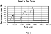
- Fig. 9 shows a graph representing results obtained from testing an embodiment of a spinal rod 20, as described above.
- the graph demonstrates that peak forces of six hundred Newton's (600 N) were observed upon hydraulically expanding spinal rod 20, as well as lower forces.
- spinal rod 20 is capable of exerting forces of up to six hundred Newton's (600 N) or more on a patient's spinal column to correct the curvature thereof.
- the amount of force required to expand a spinal rod, in situ increases with each surgical intervention.
- Peak forces needed at, for example, the tenth lengthening procedure might be on the order of six hundred Newton's (600 N), while the first and third lengthening procedures might be one-hundred and forty (140 N) and one-hundred and sixty five (165 N) Newton's, respectively.
- Other existing expandable spinal rods have difficultly achieving the peak forces required for later-stage lengthening procedures, but due to the construction of the present spinal rod 20, peak forces needed for late-stage lengthening procedures can be achieved.
- the graph shown in Fig. 9 also does not represent failure testing for spinal rod 20, and rather it merely reflects testing to establish clinical efficacy. As such, rods 20 may exert even greater loads than those exemplified in Fig. 9 and still be within normal operating parameters. As an example, greater loading of rod 20 is possible using the pump mechanism of Fig. 10 , as detailed above.
- rod 20 is the minimal or no surgical intervention that is required at each lengthening procedure. If surgical intervention is required, the minimally-invasive nature thereof is due in part to the closeness of injection port 38 and set-screw opening 54, in terms of proximity/location. Indeed, in one embodiment injection port 38 and set-screw opening 54 are spaced apart by about eight millimeters (8 mm). In another case, the distance may be anywhere from about five millimeters to about nine millimeters (5-9 mm). This small separation allows only a minimal incision to be made in the patient (e.g., of the size mentioned above) to gain access to both components of spinal rod 20 needed for expansion. In other words, as reflected by the closeness of screw driver 14 and syringe 16 in Figs.
- rod 20 only a small incision is needed to access the components necessary to expand rod 20 (i.e., injection port 38 and set screw 56). Thus, only a small incision is needed to affect expansion of rod 20, leading to only minor surgical trauma/side effects for the patient. In the case of using a pump mechanism, typically no surgical intervention is required.
- An additional benefit to rod 20 is that the patient will have increased thoracic growth because of the constant distraction pressure versus repetitive distractions performed at separate surgeries.
- rod 20 it is also possible to construct rod 20 so that injection port 38 and opening 54 are co-axial (e.g., they are the same opening) to experience possible greater benefits.
- capture nut 50 may not include opening 54 and instead injection port 38 may serve as a set-screw opening in addition to an injection port opening.
- injection port 38 would communicate directly with internal cavity 32 so that set screw 56 could be screwed into injection port 38 and bear on piston rod 60.
- set screw 56 could itself include an opening that, when aligned appropriately with flow channel 40, would create a fluid flow channel through set screw 56 (in particular through its opening), into flow channel 40, through opening 42, and into hydraulic pressure chamber 44.
- internal cavity 32 could be sealed off from fluid interaction during an expansion procedure, for example because the end of set screw 56 is closed and fluid flow would only be possible through the opening in set screw 56 and into flow channel 40.
- the driver-engaging portion of set screw 56 may include threads for interacting with, for example, distal end of syringe 16.
- syringe 16 and screw driver 14 may be made into a combination instrument.
- the benefits of the close proximity between injection port 38 and set-screw opening 54 are apparent, as are the benefits resulting from an embodiment in which only a single opening is provided, as discussed above. Namely, only a small incision is needed to access such components and cause expansion of rod 20. Thus, the patient experiences less trauma and/or negative side effects.
- FIGs. 8A-B An alternate embodiment of a spinal rod 120 is shown in Figs. 8A-B .
- Like numerals refer to like elements in this embodiment, but with numbers in the 100 series, and only the differences between spinal rods 20, 120 will be discussed.
- Spinal rod 120 includes a different lengthening/locking structure as compared to spinal rod 20.
- a ratcheting mechanism is used to achieve lengthening and locking of piston rod 160.
- the ratcheting mechanism includes a capture nut 150, which has an opening 154 leading to an internal cavity 157. Inside of internal cavity 157 is a pawl 151 having one or more teeth that are sized to interact with teeth 161 formed on piston rod 160. Pawl 151 rests on a spring 153 disposed at a bottom end of internal cavity 157, which biases pawl 151 in the direction of opening 154.
- spring 153 includes a set of legs 159 that rest, respectively, on a surface of pawl 151 and a floor defining internal cavity 157. In between legs 159 is a curvilinear segment forming the remainder of spring 153. As pawl 151 acts on legs 159 and the remainder of spring 153, spring 153 is caused to flex and allow for movement of pawl 151. As such, piston rod 160 can move in one direction due to movement of pawl 151 against spring 153 and out of engagement with teeth 161. As an example, pawl 151 can flex against spring 153 and allow movement of piston rod 160 in an expansion direction (left in Figs. 8A-B ), but not a contraction direction (right in Figs. 8A-B ).
- pawl 151 can engage successive teeth 161 on piston rod 160 and ensure that piston rod 160 is locked relative to hydraulic cylinder 130 and static rod 122. In this embodiment, a set screw mechanism is therefore not needed.
- rod 120 also includes a release mechanism 155 for allowing movement of piston rod 160 in the contraction direction.
- Release mechanism 155 may constitute an integral or unitary part of pawl 151 (e.g., a top portion or button thereof).
- pawl 151 may be a tubular or cylindrical structure with a passageway 163 for accommodating piston rod 160, which is slightly larger in diameter/dimension than a diameter/dimension of piston rod 160.
- release mechanism 155 of pawl 151 may be depressed by a user against the action of spring 153 to disengage the tooth or teeth of pawl 151 from the teeth 161 of piston rod 160. This would allow piston rod 160 to move in the contraction direction, as needed.
- a user may utilize a tool to depress release mechanism 155 and consequently allow disengagement of pawl 151 from teeth 161 to permit movement of piston rod 160 in the contraction direction.
- release mechanism 155 may be used and the length of rod 120 may be shortened. While not mentioned above, it is to be appreciated that this type of contraction/shortening is also possible with set screw 56.
- rod 120 is also usable with any pump mechanism disclosed herein, including any sub-dermal pump, for expansion of rod 120 (e.g., to maintain a constant or variable distraction force for rod 120).
- FIG. 11A-C Yet another alternate embodiment of spinal rods 20, 120 is shown in Figs. 11A-C .
- Like numerals refer to like elements in this embodiment, but with numbers in the 300 series, and only the differences between spinal rods 20, 120 and 320 will be discussed.
- rod 320 is shown as being more closely aligned with the structure of rod 20 than rod 120, in that no ratchet mechanism is used, it should be recognized that the following discussion concerning rod 320 is equally applicable to rod 120 in the context of rod 120's ratchet mechanism. Put simply, the concepts and different structures of rod 320 can be utilized with rod 120 and its ratchet mechanism as well.
- Rod 320 includes the same structures (e.g., internal cavity 32, flow channel 40, capture nut 50, seals 66, etc.) as rod 20, although a number of those structures are not designated by reference numerals in Figs. 11A-C . For simplicity's sake, only the distinctions between rod 20 and rod 320 are highlighted.
- Rod 320 is different from rod 20 in that rod 320 has a curved shape along its length, including a curvature for hydraulic cylinder 330. Such curvature produces, for example, a curved internal cavity and a curved flow channel (both not designated by a reference numeral) extending to hydraulic pressure chamber 344.
- the internal cavity of hydraulic cylinder 330 is curved along its length due to the curvature of hydraulic cylinder 330, and the flow channel leading to hydraulic pressure chamber 344 is likewise curved.
- piston rod 360 of rod 320 is curved upwards for fixation to the lumbar spine exhibiting a lordotic curvature
- hydraulic cylinder 330 is curved upwards and transitions to less of an upward curve as it approaches static rod 322 (e.g., hydraulic cylinder 330 has a variable curvature)
- static rod 322 is curved downwards for fixation to the thoracic spine exhibiting a kyphotic curvature.
- the curvature of piston rod 360, hydraulic cylinder 330, and static rod 322 may follow an axis 370 that forms a substantially S-shaped curve.
- hydraulic cylinder 330 may transition from less of an upward curve to a downward curve as it approaches piston rod 322.
- the curved nature of rod 320 may be utilized in connection with rod 120 and its ratchet structure, although not described in detail herein.
- any connecting structures are shown as being adapted for use in the implantation, distraction, and/or removal of hydraulically-expandable spinal rods according to the present invention(s).
- the invention(s) also contemplates the use of any alternative structures for such purposes, including structures having different lengths, shapes, and/or configurations.
- threaded structures in many cases (e.g., threaded end 36, 136 of hydraulic cylinder 30, 130, threaded injection port 38, 138, etc.), it is equally contemplated that non-threaded alternative engagement structures can be used.
- press-fit, bayoneted engagement structures, and/or ball-and-detent engagement structures may be used.
- any connecting structures can be used.
- hydraulic mechanism herein is described as a hydraulic cylinder 30, 130 it is not necessarily tied to that shape and any suitable shape can be used (e.g., square, rectangular, triangular, hexagonal, etc.) The same is true for hydraulic cylinder 30, 130's internal cavity 32, 132 and other components (e.g., end portion 62, 162 of piston rod 60, 160 fitting within such cavity 32, 132).
- rods 20, 120 herein are described as being formed from multiple components, such rods 20, 120 may instead be 3D printed to provide for less components and more unitary structures.
- static rod 22, 122 and hydraulic cylinder 30, 130 may be 3D printed as a single component, along with injection port 38, 138 and flow channel 40, 140 (which are welded to hydraulic cylinder 30, 130 in the main embodiment).
Landscapes
- Health & Medical Sciences (AREA)
- Orthopedic Medicine & Surgery (AREA)
- Life Sciences & Earth Sciences (AREA)
- Neurology (AREA)
- Surgery (AREA)
- Heart & Thoracic Surgery (AREA)
- General Health & Medical Sciences (AREA)
- Biomedical Technology (AREA)
- Nuclear Medicine, Radiotherapy & Molecular Imaging (AREA)
- Medical Informatics (AREA)
- Molecular Biology (AREA)
- Animal Behavior & Ethology (AREA)
- Engineering & Computer Science (AREA)
- Public Health (AREA)
- Veterinary Medicine (AREA)
- Physics & Mathematics (AREA)
- Electromagnetism (AREA)
- Surgical Instruments (AREA)
- Prostheses (AREA)
Priority Applications (1)
| Application Number | Priority Date | Filing Date | Title |
|---|---|---|---|
| EP18176053.9A EP3403604B1 (en) | 2015-01-13 | 2016-01-13 | Growing rods |
Applications Claiming Priority (1)
| Application Number | Priority Date | Filing Date | Title |
|---|---|---|---|
| US201562102778P | 2015-01-13 | 2015-01-13 |
Related Child Applications (1)
| Application Number | Title | Priority Date | Filing Date |
|---|---|---|---|
| EP18176053.9A Division EP3403604B1 (en) | 2015-01-13 | 2016-01-13 | Growing rods |
Publications (2)
| Publication Number | Publication Date |
|---|---|
| EP3047810A1 EP3047810A1 (en) | 2016-07-27 |
| EP3047810B1 true EP3047810B1 (en) | 2018-06-13 |
Family
ID=55129658
Family Applications (2)
| Application Number | Title | Priority Date | Filing Date |
|---|---|---|---|
| EP16151087.0A Active EP3047810B1 (en) | 2015-01-13 | 2016-01-13 | Growing rods and methods of use |
| EP18176053.9A Active EP3403604B1 (en) | 2015-01-13 | 2016-01-13 | Growing rods |
Family Applications After (1)
| Application Number | Title | Priority Date | Filing Date |
|---|---|---|---|
| EP18176053.9A Active EP3403604B1 (en) | 2015-01-13 | 2016-01-13 | Growing rods |
Country Status (5)
| Country | Link |
|---|---|
| US (3) | US10092328B2 (https=) |
| EP (2) | EP3047810B1 (https=) |
| JP (1) | JP6723746B2 (https=) |
| AU (2) | AU2016200177B2 (https=) |
| CA (1) | CA2917676A1 (https=) |
Families Citing this family (32)
| Publication number | Priority date | Publication date | Assignee | Title |
|---|---|---|---|---|
| JP2012507340A (ja) * | 2008-10-31 | 2012-03-29 | ミルックス・ホールディング・エスエイ | エネルギーの無線伝送を使用して骨調節を操作するためのデバイスおよび方法 |
| FR3010628B1 (fr) | 2013-09-18 | 2015-10-16 | Medicrea International | Procede permettant de realiser la courbure ideale d'une tige d'un materiel d'osteosynthese vertebrale destinee a etayer la colonne vertebrale d'un patient |
| FR3012030B1 (fr) | 2013-10-18 | 2015-12-25 | Medicrea International | Procede permettant de realiser la courbure ideale d'une tige d'un materiel d'osteosynthese vertebrale destinee a etayer la colonne vertebrale d'un patient |
| US9833262B2 (en) * | 2014-08-04 | 2017-12-05 | Warsaw Orthopedic, Inc. | Spinal correction system and method |
| US9931138B2 (en) * | 2014-10-15 | 2018-04-03 | Globus Medical, Inc. | Orthopedic extendable rods |
| CA2917676A1 (en) | 2015-01-13 | 2016-07-13 | Stryker European Holdings I, Llc | Growing rods and methods of use |
| DE102015109624A1 (de) * | 2015-06-16 | 2016-12-22 | Wittenstein Se | Mechatronisches Implantat |
| US11006977B2 (en) * | 2015-10-05 | 2021-05-18 | Global Medical Inc | Growing rod for treating spinal deformities and method for using same |
| AU2016349705B2 (en) | 2015-11-04 | 2021-07-29 | Medicrea International | Methods and Apparatus for spinal reconstructive surgery and measuring spinal length and intervertebral spacing, tension and rotation |
| US10722372B2 (en) * | 2016-07-05 | 2020-07-28 | Howmedica Osteonics Corp. | Hinge knee preparation instrumentation and associated methods |
| US10335199B2 (en) * | 2016-07-28 | 2019-07-02 | Warsaw Orthopedic. Inc. | Spinal correction construct and method |
| JP7086973B2 (ja) * | 2016-10-24 | 2022-06-20 | インディウス メディカル テクノロジーズ プライベート リミティド | 自己作動成長ロッドシステム |
| WO2018109556A1 (en) | 2016-12-12 | 2018-06-21 | Medicrea International | Systems and methods for patient-specific spinal implants |
| AU2018255892A1 (en) | 2017-04-21 | 2019-11-07 | Medicrea International | A system for providing intraoperative tracking to assist spinal surgery |
| US10918422B2 (en) | 2017-12-01 | 2021-02-16 | Medicrea International | Method and apparatus for inhibiting proximal junctional failure |
| JP6502587B1 (ja) * | 2018-02-28 | 2019-04-17 | 国立大学法人北海道大学 | ロッド群、弓状ロッド群、脊柱安定化システム、およびロッドの製造方法 |
| US11446064B2 (en) * | 2018-04-26 | 2022-09-20 | Stryker European Operations Holdings Llc | Orthopedic growing devices |
| WO2020152171A2 (de) | 2019-01-24 | 2020-07-30 | Augustin Betz | Gekrümmter marknagel |
| WO2020187463A1 (de) | 2019-03-15 | 2020-09-24 | Augustin Betz | Verbindungsvorrichtung zum verbinden zweier knochenteile |
| US11877801B2 (en) | 2019-04-02 | 2024-01-23 | Medicrea International | Systems, methods, and devices for developing patient-specific spinal implants, treatments, operations, and/or procedures |
| US11944385B2 (en) | 2019-04-02 | 2024-04-02 | Medicrea International | Systems and methods for medical image analysis |
| US11925417B2 (en) | 2019-04-02 | 2024-03-12 | Medicrea International | Systems, methods, and devices for developing patient-specific spinal implants, treatments, operations, and/or procedures |
| US12564447B2 (en) | 2019-04-02 | 2026-03-03 | Medicrea International | Systems, methods, and devices for developing patient-specific spinal implants, treatments, operations, and/or procedures |
| CN110840637A (zh) * | 2019-12-17 | 2020-02-28 | 北京爱康宜诚医疗器材有限公司 | 椎体伸长装置 |
| US11769251B2 (en) | 2019-12-26 | 2023-09-26 | Medicrea International | Systems and methods for medical image analysis |
| US20210330358A1 (en) * | 2020-04-27 | 2021-10-28 | Indius Medical Technologies Private Limited | Gradually expanding limb reconstruction systems |
| US12318144B2 (en) | 2021-06-23 | 2025-06-03 | Medicrea International SA | Systems and methods for planning a patient-specific spinal correction |
| DE102021127020A1 (de) | 2021-10-19 | 2023-04-20 | Augustin Betz | Gekrümmter Marknagel |
| US12064143B2 (en) | 2022-10-28 | 2024-08-20 | Warsaw Orthopedic, Inc. | Spinal correction system and method |
| US12551248B2 (en) | 2022-12-16 | 2026-02-17 | Arthrex, Inc. | Surgical devices for applying compression within or across joints |
| US12329415B2 (en) | 2023-02-03 | 2025-06-17 | Warsaw Orthopedic, Inc. | Spinal rod with multiple sections having eccentric centers |
| CN119924963B (zh) * | 2025-04-07 | 2025-11-28 | 天津正天医疗器械有限公司 | 生长棒和矫形固定系统 |
Citations (1)
| Publication number | Priority date | Publication date | Assignee | Title |
|---|---|---|---|---|
| WO2016061288A1 (en) * | 2014-10-15 | 2016-04-21 | Globus Medical, Inc. | Orthopedic extendable rods |
Family Cites Families (136)
| Publication number | Priority date | Publication date | Assignee | Title |
|---|---|---|---|---|
| CH581988A5 (https=) | 1974-04-09 | 1976-11-30 | Messerschmitt Boelkow Blohm | |
| FI53062C (https=) | 1975-05-30 | 1978-02-10 | Erkki Einari Nissinen | |
| DE2713837C2 (de) | 1977-03-25 | 1978-10-26 | Erhard Dr. 1000 Berlin Westerhoff | Antriebsvorrichtung für ein Distraktionsgerät |
| US4289123A (en) | 1980-03-31 | 1981-09-15 | Dunn Harold K | Orthopedic appliance |
| DE3121271A1 (de) | 1981-05-29 | 1982-12-23 | Max Bernhard 7900 Ulm Ulrich | Distraktionsgeraet zur korrektur insbesondere kyphotischer wirbelsaeulenbereiche |
| DE3306657C2 (de) | 1983-02-25 | 1986-12-11 | Fa. Heinrich C. Ulrich, 7900 Ulm | Implantat zur Wirbelsäulenkorrektur mit einem Distraktionsstab |
| US4611580A (en) | 1983-11-23 | 1986-09-16 | Henry Ford Hospital | Intervertebral body stabilization |
| US4611582A (en) | 1983-12-27 | 1986-09-16 | Wisconsin Alumni Research Foundation | Vertebral clamp |
| SE458417B (sv) | 1985-08-15 | 1989-04-03 | Sven Olerud | Fixationsinstrument avsett foer anvaendning vid ryggoperationer |
| WO1987007134A1 (en) | 1986-05-30 | 1987-12-03 | John Bumpus | Distraction rods |
| DE8704901U1 (de) | 1987-04-02 | 1987-07-23 | Kluger, Patrick, Dr.med., 3590 Bad Wildungen | Vorrichtung zum Einrichten einer Wirbelsäule mit geschädigten Wirbelkörpern |
| US4969884A (en) | 1988-12-28 | 1990-11-13 | Alza Corporation | Osmotically driven syringe |
| FR2642643B1 (fr) | 1989-02-09 | 1991-05-10 | Vignaud Jean Louis | Instrumentation rachidienne pour fixation pediculaire universelle par vis diapason a reglage micrometrique |
| DE9006646U1 (de) | 1990-06-13 | 1990-08-23 | Howmedica GmbH, 2314 Schönkirchen | Vorrichtung zum Verspannen von Wirbeln der menschlichen Wirbelsäule |
| US5034011A (en) | 1990-08-09 | 1991-07-23 | Advanced Spine Fixation Systems Incorporated | Segmental instrumentation of the posterior spine |
| US5626579A (en) | 1993-02-12 | 1997-05-06 | The Cleveland Clinic Foundation | Bone transport and lengthening system |
| US5536269A (en) * | 1993-02-18 | 1996-07-16 | Genesis Orthopedics | Bone and tissue lengthening device |
| US5350379A (en) * | 1993-02-18 | 1994-09-27 | Genesis Orthopedics | Bone and tissue lengthening device |
| US5505733A (en) | 1993-10-22 | 1996-04-09 | Justin; Daniel F. | Intramedullary skeletal distractor and method |
| US5762599A (en) | 1994-05-02 | 1998-06-09 | Influence Medical Technologies, Ltd. | Magnetically-coupled implantable medical devices |
| DE69507333T2 (de) | 1994-11-16 | 1999-09-02 | Soubeiran | Vorrichtung zum verschieben zweier körper zueinander |
| US5575790A (en) | 1995-03-28 | 1996-11-19 | Rensselaer Polytechnic Institute | Shape memory alloy internal linear actuator for use in orthopedic correction |
| US5704939A (en) | 1996-04-09 | 1998-01-06 | Justin; Daniel F. | Intramedullary skeletal distractor and method |
| US5810815A (en) | 1996-09-20 | 1998-09-22 | Morales; Jose A. | Surgical apparatus for use in the treatment of spinal deformities |
| DE19700225A1 (de) | 1997-01-07 | 1998-07-09 | Augustin Prof Dr Betz | Distraktionsvorrichtung zum Auseinanderbewegen zweier Teile eines Knochens |
| ATE334629T1 (de) | 1998-05-19 | 2006-08-15 | Synthes Ag | Verbindungselement für monolaterales externes fixationssystem für traumatologie und orthopädie |
| US6261289B1 (en) | 1998-10-26 | 2001-07-17 | Mark Levy | Expandable orthopedic device |
| DE19906423A1 (de) | 1999-02-16 | 2000-08-17 | Wittenstein Gmbh & Co Kg | Aktiver Marknagel zur Distraktion von Knochenteilen |
| US7008425B2 (en) | 1999-05-27 | 2006-03-07 | Jonathan Phillips | Pediatric intramedullary nail and method |
| GB0009107D0 (en) | 2000-04-13 | 2000-05-31 | Univ London | Surgical distraction device |
| US6964667B2 (en) | 2000-06-23 | 2005-11-15 | Sdgi Holdings, Inc. | Formed in place fixation system with thermal acceleration |
| DE10055519A1 (de) | 2000-11-09 | 2002-06-06 | Wittenstein Gmbh & Co Kg | Distraktionsvorrichtung |
| MXPA03004216A (es) | 2000-12-08 | 2003-09-22 | Synthes Ag | Dispositivo para la fijacion de huesos, en especial de cuerpos vertebrales, entre si. |
| US6632203B2 (en) | 2001-05-21 | 2003-10-14 | Sherwood Services Ag | Sampling port for a drainage device |
| JP4175899B2 (ja) | 2001-05-23 | 2008-11-05 | オーソゴン テクノロジーズ 2003 リミテッド | 磁気駆動可能な髄内装置 |
| US6991632B2 (en) | 2001-09-28 | 2006-01-31 | Stephen Ritland | Adjustable rod and connector device and method of use |
| DE10156316A1 (de) | 2001-11-19 | 2003-06-05 | Wittenstein Ag | Distraktionsvorrichtung |
| US7601156B2 (en) | 2001-12-05 | 2009-10-13 | Randolph C. Robinson | Limb lengthener |
| US7011658B2 (en) | 2002-03-04 | 2006-03-14 | Sdgi Holdings, Inc. | Devices and methods for spinal compression and distraction |
| US20030220643A1 (en) | 2002-05-24 | 2003-11-27 | Ferree Bret A. | Devices to prevent spinal extension |
| US6918910B2 (en) | 2002-12-16 | 2005-07-19 | John T. Smith | Implantable distraction device |
| DE10317776A1 (de) | 2003-04-16 | 2004-11-04 | Wittenstein Ag | Vorrichtung zum Verlängern von Knochen oder Knochenteilen |
| US8415407B2 (en) | 2004-03-21 | 2013-04-09 | Depuy Spine, Inc. | Methods, materials, and apparatus for treating bone and other tissue |
| WO2005027763A1 (de) | 2003-08-28 | 2005-03-31 | Wittenstein Ag | Planetenrollensystem, insbesondere für eine vorrichtung zum verlängern von knochen |
| DE10340025A1 (de) | 2003-08-28 | 2005-03-24 | Wittenstein Ag | Vorrichtung zum Verlängern von Knochen oder Knochenteilen |
| US7699879B2 (en) | 2003-10-21 | 2010-04-20 | Warsaw Orthopedic, Inc. | Apparatus and method for providing dynamizable translations to orthopedic implants |
| US7320324B2 (en) | 2004-04-15 | 2008-01-22 | Willeford Kenneth L | Bronchoscopy oxygenation system |
| US20050277921A1 (en) * | 2004-05-28 | 2005-12-15 | Sdgi Holdings, Inc. | Prosthetic joint and nucleus supplement |
| GB2414674B (en) | 2004-06-04 | 2009-08-12 | John Burke | Apparatus for the correction of skeletal deformities |
| US7938848B2 (en) | 2004-06-09 | 2011-05-10 | Life Spine, Inc. | Spinal fixation system |
| US7776091B2 (en) | 2004-06-30 | 2010-08-17 | Depuy Spine, Inc. | Adjustable posterior spinal column positioner |
| US7481841B2 (en) | 2004-06-30 | 2009-01-27 | Depuy Products, Inc. | Adjustable orthopaedic prosthesis and associated method |
| US7955357B2 (en) | 2004-07-02 | 2011-06-07 | Ellipse Technologies, Inc. | Expandable rod system to treat scoliosis and method of using the same |
| US20060036324A1 (en) | 2004-08-03 | 2006-02-16 | Dan Sachs | Adjustable spinal implant device and method |
| US7763053B2 (en) | 2004-08-30 | 2010-07-27 | Gordon Jeffrey D | Implant for correction of spinal deformity |
| US8142454B2 (en) | 2004-09-29 | 2012-03-27 | The Regents Of The University Of California, San Francisco | Apparatus and method for magnetic alteration of anatomical features |
| US8915915B2 (en) | 2004-09-29 | 2014-12-23 | The Regents Of The University Of California | Apparatus and methods for magnetic alteration of anatomical features |
| US8043290B2 (en) | 2004-09-29 | 2011-10-25 | The Regents Of The University Of California, San Francisco | Apparatus and methods for magnetic alteration of deformities |
| US8439915B2 (en) | 2004-09-29 | 2013-05-14 | The Regents Of The University Of California | Apparatus and methods for magnetic alteration of anatomical features |
| US8623036B2 (en) | 2004-09-29 | 2014-01-07 | The Regents Of The University Of California | Magnamosis |
| US20060106381A1 (en) | 2004-11-18 | 2006-05-18 | Ferree Bret A | Methods and apparatus for treating spinal stenosis |
| US7927357B2 (en) | 2005-02-02 | 2011-04-19 | Depuy Spine, Inc. | Adjustable length implant |
| US7942908B2 (en) * | 2005-02-02 | 2011-05-17 | Depuy Spine, Inc. | Adjustable length implant |
| US20090118774A1 (en) * | 2005-02-09 | 2009-05-07 | Mavrek Medical, Llc. | Sternal Closure Device with Ratchet Closure Mechanism |
| US8100943B2 (en) | 2005-02-17 | 2012-01-24 | Kyphon Sarl | Percutaneous spinal implants and methods |
| US7591853B2 (en) * | 2005-03-09 | 2009-09-22 | Vertebral Technologies, Inc. | Rail-based modular disc nucleus prosthesis |
| EP1896192A1 (en) | 2005-06-29 | 2008-03-12 | Medmix Systems AG | Method and device for venting and eliminating unwanted material of a dispensing appliance |
| US8486070B2 (en) | 2005-08-23 | 2013-07-16 | Smith & Nephew, Inc. | Telemetric orthopaedic implant |
| US7655026B2 (en) | 2006-01-31 | 2010-02-02 | Warsaw Orthopedic, Inc. | Expandable spinal rods and methods of use |
| US7776075B2 (en) | 2006-01-31 | 2010-08-17 | Warsaw Orthopedic, Inc. | Expandable spinal rods and methods of use |
| EP2001382B1 (en) | 2006-04-06 | 2015-07-29 | Synthes GmbH | Remotely adjustable tissue displacement device |
| US8298240B2 (en) | 2006-04-06 | 2012-10-30 | Synthes (Usa) | Remotely adjustable tissue displacement device |
| WO2007123920A2 (en) | 2006-04-18 | 2007-11-01 | Joseph Nicholas Logan | Spinal rod system |
| US8267905B2 (en) | 2006-05-01 | 2012-09-18 | Neurosystec Corporation | Apparatus and method for delivery of therapeutic and other types of agents |
| US8475499B2 (en) | 2006-07-14 | 2013-07-02 | DePuy Synthes Products, LLC. | Rod to rod connectors and methods of adjusting the length of a spinal rod construct |
| US7806913B2 (en) * | 2006-08-16 | 2010-10-05 | Depuy Spine, Inc. | Modular multi-level spine stabilization system and method |
| DE602007010333D1 (de) * | 2006-09-26 | 2010-12-16 | Synthes Gmbh | Transkonnektor |
| US20080177319A1 (en) | 2006-12-09 | 2008-07-24 | Helmut Schwab | Expansion Rod, Self-Adjusting |
| US8372121B2 (en) | 2007-02-08 | 2013-02-12 | Warsaw Orthopedic, Inc. | Adjustable coupling systems for spinal stabilization members |
| US20080208260A1 (en) | 2007-02-22 | 2008-08-28 | Csaba Truckai | Spine treatment devices and methods |
| US7753915B1 (en) | 2007-06-14 | 2010-07-13 | August Eksler | Bi-directional bone length adjustment system |
| CA2694437C (en) | 2007-07-26 | 2016-09-06 | Glenn R. Buttermann | Segmental orthopedic device for spinal elongation and for treatment of scoliosis |
| US20090112263A1 (en) | 2007-10-30 | 2009-04-30 | Scott Pool | Skeletal manipulation system |
| WO2009079196A1 (en) | 2007-12-15 | 2009-06-25 | Parlato Brian D | Flexible rod assembly for spinal fixation |
| US7799056B2 (en) | 2007-12-31 | 2010-09-21 | Warsaw Orthopedic, Inc. | Bone fusion device and methods |
| US8092499B1 (en) | 2008-01-11 | 2012-01-10 | Roth Herbert J | Skeletal flexible/rigid rod for treating skeletal curvature |
| US8777995B2 (en) | 2008-02-07 | 2014-07-15 | K2M, Inc. | Automatic lengthening bone fixation device |
| US20090234388A1 (en) | 2008-03-15 | 2009-09-17 | Warsaw Orthopedic, Inc. | Spinal Stabilization Connecting Element and System |
| KR101045933B1 (ko) | 2008-05-02 | 2011-07-01 | 김가브리엘민 | 교정 장치 |
| US8211149B2 (en) | 2008-05-12 | 2012-07-03 | Warsaw Orthopedic | Elongated members with expansion chambers for treating bony members |
| EP2293727A1 (en) * | 2008-05-28 | 2011-03-16 | Kerflin Orthopedic Innovations, Llc | Fluid-powered elongation instrumentation for correcting orthopedic deformities |
| EP2299917A1 (en) | 2008-06-10 | 2011-03-30 | Sonoma Orthopedic Products, Inc. | Fracture fixation device, tools and methods |
| WO2010017471A1 (en) | 2008-08-07 | 2010-02-11 | The Children's Mercy Hospital | Sliding rod system for correcting spinal deformities |
| US20100106192A1 (en) | 2008-10-27 | 2010-04-29 | Barry Mark A | System and method for aligning vertebrae in the amelioration of aberrant spinal column deviation condition in patients requiring the accomodation of spinal column growth or elongation |
| JP2012507340A (ja) * | 2008-10-31 | 2012-03-29 | ミルックス・ホールディング・エスエイ | エネルギーの無線伝送を使用して骨調節を操作するためのデバイスおよび方法 |
| JP5800428B2 (ja) | 2008-11-03 | 2015-10-28 | ジンテス ゲゼルシャフト ミット ベシュレンクテル ハフツング | 調整式ロッド組立体 |
| EP2373236B1 (en) | 2008-12-17 | 2014-05-21 | Synthes GmbH | Posterior spine dynamic stabilizer |
| US20100211105A1 (en) | 2009-02-13 | 2010-08-19 | Missoum Moumene | Telescopic Rod For Posterior Dynamic Stabilization |
| DE102009011661A1 (de) | 2009-03-04 | 2010-09-09 | Wittenstein Ag | Wachstumsprothese |
| US8202301B2 (en) | 2009-04-24 | 2012-06-19 | Warsaw Orthopedic, Inc. | Dynamic spinal rod and implantation method |
| US8292927B2 (en) | 2009-04-24 | 2012-10-23 | Warsaw Orthopedic, Inc. | Flexible articulating spinal rod |
| FR2947170B1 (fr) | 2009-06-24 | 2011-07-22 | Jean Marc Guichet | Clou d'allongement pour os long ou analogue |
| WO2011018778A1 (en) | 2009-08-13 | 2011-02-17 | Cork Institute Of Technology | Intramedullary nails for long bone fracture setting |
| GB0915382D0 (en) | 2009-09-03 | 2009-10-07 | Dalmatic As | Expansion devices |
| JP2011072471A (ja) * | 2009-09-30 | 2011-04-14 | Terumo Corp | シリンジ |
| US9327015B2 (en) | 2009-10-23 | 2016-05-03 | DePuy Synthes Products, Inc. | Methods and devices for correcting spinal deformity with pharmaceutical-eluting pedicle screws |
| US8568457B2 (en) | 2009-12-01 | 2013-10-29 | DePuy Synthes Products, LLC | Non-fusion scoliosis expandable spinal rod |
| US8585740B1 (en) | 2010-01-12 | 2013-11-19 | AMB Surgical, LLC | Automated growing rod device |
| US8764751B2 (en) | 2010-03-04 | 2014-07-01 | Skeletal Dynamics, Llc | Endosteal nail plate for fixing bone segments |
| US8777947B2 (en) | 2010-03-19 | 2014-07-15 | Smith & Nephew, Inc. | Telescoping IM nail and actuating mechanism |
| FR2957776B1 (fr) | 2010-03-23 | 2013-02-15 | Arnaud Andre Soubeiran | Dispositif de deplacement de tissus a l'interieur de l'organisme, notamment de tissus osseux, a vis travaillant en traction fixe et ecrou tournant |
| WO2011116773A1 (en) | 2010-03-24 | 2011-09-29 | Aarhus Universitet | Implant for treatment of skeletal deformities |
| US8734488B2 (en) | 2010-08-09 | 2014-05-27 | Ellipse Technologies, Inc. | Maintenance feature in magnetic implant |
| US20120271353A1 (en) | 2010-08-16 | 2012-10-25 | Mark Barry | System and method for aligning vertebrae in the amelioration of aberrant spinal column deviation conditions in patients requiring the accomodation of spinal column growth or elongation |
| DE102010047738A1 (de) | 2010-08-26 | 2012-03-01 | Wittenstein Ag | Aktuator zur Skoliosekorrektur |
| CN103179913B (zh) | 2010-09-27 | 2016-05-18 | 阿比菲克斯有限公司 | 防倒转脊椎装置 |
| CH703974A1 (de) | 2010-10-15 | 2012-04-30 | Medmix Systems Ag | Medizinischer Sprühkopf mit Druckgasunterstützung. |
| US8961567B2 (en) | 2010-11-22 | 2015-02-24 | DePuy Synthes Products, LLC | Non-fusion scoliosis expandable spinal rod |
| EP2712304A4 (en) | 2011-05-16 | 2015-06-17 | Smith & Nephew Inc | MEASURE A SKELETAL DISTRACTION |
| DE102011053638A1 (de) | 2011-09-15 | 2013-03-21 | Wittenstein Ag | Marknagel |
| US8894688B2 (en) | 2011-10-27 | 2014-11-25 | Globus Medical Inc. | Adjustable rod devices and methods of using the same |
| DK2790600T3 (en) | 2011-12-12 | 2017-07-10 | Austen Bioinnovation Inst In Akron | Non-invasive device for adjusting a fastener |
| US10016226B2 (en) | 2011-12-12 | 2018-07-10 | Children's Hospital Medical Center Of Akron | Noninvasive device for adjusting fastener |
| US9427261B2 (en) | 2012-06-13 | 2016-08-30 | Warsaw Orthopedic, Inc. | Spinal correction system and method |
| US20130338714A1 (en) | 2012-06-15 | 2013-12-19 | Arvin Chang | Magnetic implants with improved anatomical compatibility |
| EP2712560B1 (en) | 2012-09-07 | 2014-12-24 | K2M, Inc. | Growing spinal rod system |
| WO2014075025A1 (en) | 2012-11-12 | 2014-05-15 | Ziran Navid | Dynamic axial nail for intramedullary treatment of long bone fractures |
| US9468467B2 (en) | 2013-02-01 | 2016-10-18 | DePuy Synthes Products, Inc. | Bone support apparatus |
| US9668773B2 (en) * | 2013-03-14 | 2017-06-06 | Globus Medical, Inc. | Spinal implant for use in thoracic insufficiency syndrome |
| US9919082B2 (en) | 2014-07-09 | 2018-03-20 | H&H Medical Corporation | Pneumothorax medical treatment device |
| KR102190569B1 (ko) | 2014-11-05 | 2020-12-15 | 주니어. 토마스 에스. 존스톤 | 확장기 장치용 탈착식 액츄에이터 암 |
| CA2917676A1 (en) | 2015-01-13 | 2016-07-13 | Stryker European Holdings I, Llc | Growing rods and methods of use |
| US9949759B2 (en) | 2015-10-05 | 2018-04-24 | Globus Medical, Inc. | Growing rod for treating spinal deformities and method for using same |
| US10080875B2 (en) | 2015-12-01 | 2018-09-25 | Medtronic Vascular, Inc. | Handle component for providing a pressurized material |
| US10335199B2 (en) | 2016-07-28 | 2019-07-02 | Warsaw Orthopedic. Inc. | Spinal correction construct and method |
| CN110022782A (zh) | 2016-10-26 | 2019-07-16 | 保罗·C·麦卡菲 | 用于脊柱手术的牵张工具 |
-
2016
- 2016-01-11 CA CA2917676A patent/CA2917676A1/en not_active Abandoned
- 2016-01-12 JP JP2016003474A patent/JP6723746B2/ja not_active Expired - Fee Related
- 2016-01-12 US US14/993,555 patent/US10092328B2/en active Active
- 2016-01-12 AU AU2016200177A patent/AU2016200177B2/en not_active Ceased
- 2016-01-13 EP EP16151087.0A patent/EP3047810B1/en active Active
- 2016-01-13 EP EP18176053.9A patent/EP3403604B1/en active Active
-
2017
- 2017-08-17 AU AU2017216532A patent/AU2017216532B2/en not_active Ceased
-
2018
- 2018-09-17 US US16/133,069 patent/US10952776B2/en active Active
-
2021
- 2021-01-20 US US17/153,412 patent/US11771471B2/en active Active
Patent Citations (1)
| Publication number | Priority date | Publication date | Assignee | Title |
|---|---|---|---|---|
| WO2016061288A1 (en) * | 2014-10-15 | 2016-04-21 | Globus Medical, Inc. | Orthopedic extendable rods |
Also Published As
| Publication number | Publication date |
|---|---|
| EP3403604B1 (en) | 2024-07-31 |
| AU2016200177A1 (en) | 2016-07-28 |
| US20190083144A1 (en) | 2019-03-21 |
| US20210137564A1 (en) | 2021-05-13 |
| US10952776B2 (en) | 2021-03-23 |
| AU2017216532B2 (en) | 2019-10-31 |
| US10092328B2 (en) | 2018-10-09 |
| US11771471B2 (en) | 2023-10-03 |
| JP2016129670A (ja) | 2016-07-21 |
| AU2017216532A1 (en) | 2017-09-07 |
| JP6723746B2 (ja) | 2020-07-15 |
| CA2917676A1 (en) | 2016-07-13 |
| EP3403604A1 (en) | 2018-11-21 |
| EP3047810A1 (en) | 2016-07-27 |
| AU2016200177B2 (en) | 2017-08-31 |
| US20160199101A1 (en) | 2016-07-14 |
Similar Documents
| Publication | Publication Date | Title |
|---|---|---|
| US11771471B2 (en) | Growing rods and methods of use | |
| US12446925B2 (en) | Orthopedic growing devices | |
| US8636776B2 (en) | Spinal rod approximator | |
| CN102512229B (zh) | 多轴骨固定元件 | |
| US7087057B2 (en) | Polyaxial bone screw | |
| EP3206605B1 (en) | Orthopedic extendable rods | |
| US10499969B2 (en) | Bone fixation screw with deployable anchors | |
| US20100274290A1 (en) | Position augmenting mechanism | |
| US9173687B2 (en) | Fulcrum cap for spinal constructs | |
| US20100179601A1 (en) | Threadless position augmenting mechanism | |
| AU2005302633A1 (en) | Apparatus and method for concave scoliosis expansion | |
| KR20090065528A (ko) | 정형외과용 임플란트 어셈블리 | |
| CN101522124A (zh) | 矫形植入装置 |
Legal Events
| Date | Code | Title | Description |
|---|---|---|---|
| PUAI | Public reference made under article 153(3) epc to a published international application that has entered the european phase |
Free format text: ORIGINAL CODE: 0009012 |
|
| AK | Designated contracting states |
Kind code of ref document: A1 Designated state(s): AL AT BE BG CH CY CZ DE DK EE ES FI FR GB GR HR HU IE IS IT LI LT LU LV MC MK MT NL NO PL PT RO RS SE SI SK SM TR |
|
| AX | Request for extension of the european patent |
Extension state: BA ME |
|
| STAA | Information on the status of an ep patent application or granted ep patent |
Free format text: STATUS: REQUEST FOR EXAMINATION WAS MADE |
|
| 17P | Request for examination filed |
Effective date: 20170127 |
|
| GRAP | Despatch of communication of intention to grant a patent |
Free format text: ORIGINAL CODE: EPIDOSNIGR1 |
|
| STAA | Information on the status of an ep patent application or granted ep patent |
Free format text: STATUS: GRANT OF PATENT IS INTENDED |
|
| RIC1 | Information provided on ipc code assigned before grant |
Ipc: A61B 17/70 20060101AFI20171128BHEP |
|
| INTG | Intention to grant announced |
Effective date: 20171220 |
|
| GRAS | Grant fee paid |
Free format text: ORIGINAL CODE: EPIDOSNIGR3 |
|
| GRAA | (expected) grant |
Free format text: ORIGINAL CODE: 0009210 |
|
| STAA | Information on the status of an ep patent application or granted ep patent |
Free format text: STATUS: THE PATENT HAS BEEN GRANTED |
|
| RIN1 | Information on inventor provided before grant (corrected) |
Inventor name: BUCHERT, OLIVER Inventor name: SHARIFI-MEHR, AMIR ALI |
|
| AK | Designated contracting states |
Kind code of ref document: B1 Designated state(s): AL AT BE BG CH CY CZ DE DK EE ES FI FR GB GR HR HU IE IS IT LI LT LU LV MC MK MT NL NO PL PT RO RS SE SI SK SM TR |
|
| REG | Reference to a national code |
Ref country code: GB Ref legal event code: FG4D |
|
| REG | Reference to a national code |
Ref country code: CH Ref legal event code: EP Ref country code: AT Ref legal event code: REF Ref document number: 1007663 Country of ref document: AT Kind code of ref document: T Effective date: 20180615 |
|
| REG | Reference to a national code |
Ref country code: IE Ref legal event code: FG4D |
|
| REG | Reference to a national code |
Ref country code: DE Ref legal event code: R096 Ref document number: 602016003401 Country of ref document: DE |
|
| REG | Reference to a national code |
Ref country code: NL Ref legal event code: MP Effective date: 20180613 |
|
| REG | Reference to a national code |
Ref country code: LT Ref legal event code: MG4D |
|
| PG25 | Lapsed in a contracting state [announced via postgrant information from national office to epo] |
Ref country code: CY Free format text: LAPSE BECAUSE OF FAILURE TO SUBMIT A TRANSLATION OF THE DESCRIPTION OR TO PAY THE FEE WITHIN THE PRESCRIBED TIME-LIMIT Effective date: 20180613 Ref country code: LT Free format text: LAPSE BECAUSE OF FAILURE TO SUBMIT A TRANSLATION OF THE DESCRIPTION OR TO PAY THE FEE WITHIN THE PRESCRIBED TIME-LIMIT Effective date: 20180613 Ref country code: NO Free format text: LAPSE BECAUSE OF FAILURE TO SUBMIT A TRANSLATION OF THE DESCRIPTION OR TO PAY THE FEE WITHIN THE PRESCRIBED TIME-LIMIT Effective date: 20180913 Ref country code: SE Free format text: LAPSE BECAUSE OF FAILURE TO SUBMIT A TRANSLATION OF THE DESCRIPTION OR TO PAY THE FEE WITHIN THE PRESCRIBED TIME-LIMIT Effective date: 20180613 Ref country code: ES Free format text: LAPSE BECAUSE OF FAILURE TO SUBMIT A TRANSLATION OF THE DESCRIPTION OR TO PAY THE FEE WITHIN THE PRESCRIBED TIME-LIMIT Effective date: 20180613 Ref country code: FI Free format text: LAPSE BECAUSE OF FAILURE TO SUBMIT A TRANSLATION OF THE DESCRIPTION OR TO PAY THE FEE WITHIN THE PRESCRIBED TIME-LIMIT Effective date: 20180613 Ref country code: BG Free format text: LAPSE BECAUSE OF FAILURE TO SUBMIT A TRANSLATION OF THE DESCRIPTION OR TO PAY THE FEE WITHIN THE PRESCRIBED TIME-LIMIT Effective date: 20180913 |
|
| PG25 | Lapsed in a contracting state [announced via postgrant information from national office to epo] |
Ref country code: RS Free format text: LAPSE BECAUSE OF FAILURE TO SUBMIT A TRANSLATION OF THE DESCRIPTION OR TO PAY THE FEE WITHIN THE PRESCRIBED TIME-LIMIT Effective date: 20180613 Ref country code: LV Free format text: LAPSE BECAUSE OF FAILURE TO SUBMIT A TRANSLATION OF THE DESCRIPTION OR TO PAY THE FEE WITHIN THE PRESCRIBED TIME-LIMIT Effective date: 20180613 Ref country code: GR Free format text: LAPSE BECAUSE OF FAILURE TO SUBMIT A TRANSLATION OF THE DESCRIPTION OR TO PAY THE FEE WITHIN THE PRESCRIBED TIME-LIMIT Effective date: 20180914 Ref country code: HR Free format text: LAPSE BECAUSE OF FAILURE TO SUBMIT A TRANSLATION OF THE DESCRIPTION OR TO PAY THE FEE WITHIN THE PRESCRIBED TIME-LIMIT Effective date: 20180613 |
|
| REG | Reference to a national code |
Ref country code: AT Ref legal event code: MK05 Ref document number: 1007663 Country of ref document: AT Kind code of ref document: T Effective date: 20180613 |
|
| PG25 | Lapsed in a contracting state [announced via postgrant information from national office to epo] |
Ref country code: NL Free format text: LAPSE BECAUSE OF FAILURE TO SUBMIT A TRANSLATION OF THE DESCRIPTION OR TO PAY THE FEE WITHIN THE PRESCRIBED TIME-LIMIT Effective date: 20180613 |
|
| PG25 | Lapsed in a contracting state [announced via postgrant information from national office to epo] |
Ref country code: AT Free format text: LAPSE BECAUSE OF FAILURE TO SUBMIT A TRANSLATION OF THE DESCRIPTION OR TO PAY THE FEE WITHIN THE PRESCRIBED TIME-LIMIT Effective date: 20180613 Ref country code: IS Free format text: LAPSE BECAUSE OF FAILURE TO SUBMIT A TRANSLATION OF THE DESCRIPTION OR TO PAY THE FEE WITHIN THE PRESCRIBED TIME-LIMIT Effective date: 20181013 Ref country code: SK Free format text: LAPSE BECAUSE OF FAILURE TO SUBMIT A TRANSLATION OF THE DESCRIPTION OR TO PAY THE FEE WITHIN THE PRESCRIBED TIME-LIMIT Effective date: 20180613 Ref country code: EE Free format text: LAPSE BECAUSE OF FAILURE TO SUBMIT A TRANSLATION OF THE DESCRIPTION OR TO PAY THE FEE WITHIN THE PRESCRIBED TIME-LIMIT Effective date: 20180613 Ref country code: PL Free format text: LAPSE BECAUSE OF FAILURE TO SUBMIT A TRANSLATION OF THE DESCRIPTION OR TO PAY THE FEE WITHIN THE PRESCRIBED TIME-LIMIT Effective date: 20180613 Ref country code: RO Free format text: LAPSE BECAUSE OF FAILURE TO SUBMIT A TRANSLATION OF THE DESCRIPTION OR TO PAY THE FEE WITHIN THE PRESCRIBED TIME-LIMIT Effective date: 20180613 Ref country code: CZ Free format text: LAPSE BECAUSE OF FAILURE TO SUBMIT A TRANSLATION OF THE DESCRIPTION OR TO PAY THE FEE WITHIN THE PRESCRIBED TIME-LIMIT Effective date: 20180613 |
|
| PG25 | Lapsed in a contracting state [announced via postgrant information from national office to epo] |
Ref country code: SM Free format text: LAPSE BECAUSE OF FAILURE TO SUBMIT A TRANSLATION OF THE DESCRIPTION OR TO PAY THE FEE WITHIN THE PRESCRIBED TIME-LIMIT Effective date: 20180613 Ref country code: IT Free format text: LAPSE BECAUSE OF FAILURE TO SUBMIT A TRANSLATION OF THE DESCRIPTION OR TO PAY THE FEE WITHIN THE PRESCRIBED TIME-LIMIT Effective date: 20180613 |
|
| REG | Reference to a national code |
Ref country code: DE Ref legal event code: R097 Ref document number: 602016003401 Country of ref document: DE |
|
| PLBE | No opposition filed within time limit |
Free format text: ORIGINAL CODE: 0009261 |
|
| STAA | Information on the status of an ep patent application or granted ep patent |
Free format text: STATUS: NO OPPOSITION FILED WITHIN TIME LIMIT |
|
| 26N | No opposition filed |
Effective date: 20190314 |
|
| PG25 | Lapsed in a contracting state [announced via postgrant information from national office to epo] |
Ref country code: DK Free format text: LAPSE BECAUSE OF FAILURE TO SUBMIT A TRANSLATION OF THE DESCRIPTION OR TO PAY THE FEE WITHIN THE PRESCRIBED TIME-LIMIT Effective date: 20180613 Ref country code: SI Free format text: LAPSE BECAUSE OF FAILURE TO SUBMIT A TRANSLATION OF THE DESCRIPTION OR TO PAY THE FEE WITHIN THE PRESCRIBED TIME-LIMIT Effective date: 20180613 |
|
| PG25 | Lapsed in a contracting state [announced via postgrant information from national office to epo] |
Ref country code: MC Free format text: LAPSE BECAUSE OF FAILURE TO SUBMIT A TRANSLATION OF THE DESCRIPTION OR TO PAY THE FEE WITHIN THE PRESCRIBED TIME-LIMIT Effective date: 20180613 |
|
| REG | Reference to a national code |
Ref country code: CH Ref legal event code: PL |
|
| PG25 | Lapsed in a contracting state [announced via postgrant information from national office to epo] |
Ref country code: LU Free format text: LAPSE BECAUSE OF NON-PAYMENT OF DUE FEES Effective date: 20190113 |
|
| REG | Reference to a national code |
Ref country code: BE Ref legal event code: MM Effective date: 20190131 |
|
| REG | Reference to a national code |
Ref country code: IE Ref legal event code: MM4A |
|
| PG25 | Lapsed in a contracting state [announced via postgrant information from national office to epo] |
Ref country code: AL Free format text: LAPSE BECAUSE OF FAILURE TO SUBMIT A TRANSLATION OF THE DESCRIPTION OR TO PAY THE FEE WITHIN THE PRESCRIBED TIME-LIMIT Effective date: 20180613 Ref country code: BE Free format text: LAPSE BECAUSE OF NON-PAYMENT OF DUE FEES Effective date: 20190131 |
|
| PG25 | Lapsed in a contracting state [announced via postgrant information from national office to epo] |
Ref country code: LI Free format text: LAPSE BECAUSE OF NON-PAYMENT OF DUE FEES Effective date: 20190131 Ref country code: CH Free format text: LAPSE BECAUSE OF NON-PAYMENT OF DUE FEES Effective date: 20190131 |
|
| PG25 | Lapsed in a contracting state [announced via postgrant information from national office to epo] |
Ref country code: IE Free format text: LAPSE BECAUSE OF NON-PAYMENT OF DUE FEES Effective date: 20190113 |
|
| PG25 | Lapsed in a contracting state [announced via postgrant information from national office to epo] |
Ref country code: TR Free format text: LAPSE BECAUSE OF FAILURE TO SUBMIT A TRANSLATION OF THE DESCRIPTION OR TO PAY THE FEE WITHIN THE PRESCRIBED TIME-LIMIT Effective date: 20180613 |
|
| PG25 | Lapsed in a contracting state [announced via postgrant information from national office to epo] |
Ref country code: MT Free format text: LAPSE BECAUSE OF NON-PAYMENT OF DUE FEES Effective date: 20190113 Ref country code: PT Free format text: LAPSE BECAUSE OF FAILURE TO SUBMIT A TRANSLATION OF THE DESCRIPTION OR TO PAY THE FEE WITHIN THE PRESCRIBED TIME-LIMIT Effective date: 20181015 |
|
| REG | Reference to a national code |
Ref country code: DE Ref legal event code: R082 Ref document number: 602016003401 Country of ref document: DE Representative=s name: WUESTHOFF & WUESTHOFF PATENTANWAELTE UND RECHT, DE Ref country code: DE Ref legal event code: R082 Ref document number: 602016003401 Country of ref document: DE Representative=s name: WUESTHOFF & WUESTHOFF, PATENTANWAELTE PARTG MB, DE Ref country code: DE Ref legal event code: R081 Ref document number: 602016003401 Country of ref document: DE Owner name: STRYKER EUROPEAN OPERATIONS HOLDINGS LLC (N.D., US Free format text: FORMER OWNER: STRYKER EUROPEAN HOLDINGS I, LLC, KALAMAZOO, MICH., US Ref country code: DE Ref legal event code: R081 Ref document number: 602016003401 Country of ref document: DE Owner name: VB SPINE US OPCO LLC, WILMINGTON, US Free format text: FORMER OWNER: STRYKER EUROPEAN HOLDINGS I, LLC, KALAMAZOO, MICH., US |
|
| PG25 | Lapsed in a contracting state [announced via postgrant information from national office to epo] |
Ref country code: HU Free format text: LAPSE BECAUSE OF FAILURE TO SUBMIT A TRANSLATION OF THE DESCRIPTION OR TO PAY THE FEE WITHIN THE PRESCRIBED TIME-LIMIT; INVALID AB INITIO Effective date: 20160113 |
|
| REG | Reference to a national code |
Ref country code: GB Ref legal event code: 732E Free format text: REGISTERED BETWEEN 20210805 AND 20210811 |
|
| PG25 | Lapsed in a contracting state [announced via postgrant information from national office to epo] |
Ref country code: MK Free format text: LAPSE BECAUSE OF FAILURE TO SUBMIT A TRANSLATION OF THE DESCRIPTION OR TO PAY THE FEE WITHIN THE PRESCRIBED TIME-LIMIT Effective date: 20180613 |
|
| P01 | Opt-out of the competence of the unified patent court (upc) registered |
Effective date: 20230522 |
|
| REG | Reference to a national code |
Ref country code: DE Ref legal event code: R081 Ref document number: 602016003401 Country of ref document: DE Owner name: VB SPINE US OPCO LLC, WILMINGTON, US Free format text: FORMER OWNER: STRYKER EUROPEAN OPERATIONS HOLDINGS LLC (N.D.GES.D. STAATES DELAWARE), KALAMAZOO, MI, US |
|
| REG | Reference to a national code |
Ref country code: GB Ref legal event code: 732E Free format text: REGISTERED BETWEEN 20251120 AND 20251126 |
|
| PGFP | Annual fee paid to national office [announced via postgrant information from national office to epo] |
Ref country code: GB Payment date: 20251120 Year of fee payment: 11 |
|
| PGFP | Annual fee paid to national office [announced via postgrant information from national office to epo] |
Ref country code: FR Payment date: 20251124 Year of fee payment: 11 |
|
| PGFP | Annual fee paid to national office [announced via postgrant information from national office to epo] |
Ref country code: DE Payment date: 20251119 Year of fee payment: 11 |