EP3047515B1 - Mehrfach-ölemissionsmessgerät für motoren - Google Patents
Mehrfach-ölemissionsmessgerät für motoren Download PDFInfo
- Publication number
- EP3047515B1 EP3047515B1 EP14772309.2A EP14772309A EP3047515B1 EP 3047515 B1 EP3047515 B1 EP 3047515B1 EP 14772309 A EP14772309 A EP 14772309A EP 3047515 B1 EP3047515 B1 EP 3047515B1
- Authority
- EP
- European Patent Office
- Prior art keywords
- oil
- emissions
- measuring
- measuring device
- designed
- Prior art date
- Legal status (The legal status is an assumption and is not a legal conclusion. Google has not performed a legal analysis and makes no representation as to the accuracy of the status listed.)
- Active
Links
Images

Classifications
-
- H—ELECTRICITY
- H01—ELECTRIC ELEMENTS
- H01J—ELECTRIC DISCHARGE TUBES OR DISCHARGE LAMPS
- H01J49/00—Particle spectrometers or separator tubes
- H01J49/02—Details
- H01J49/04—Arrangements for introducing or extracting samples to be analysed, e.g. vacuum locks; Arrangements for external adjustment of electron- or ion-optical components
- H01J49/0422—Arrangements for introducing or extracting samples to be analysed, e.g. vacuum locks; Arrangements for external adjustment of electron- or ion-optical components for gaseous samples
-
- G—PHYSICS
- G01—MEASURING; TESTING
- G01N—INVESTIGATING OR ANALYSING MATERIALS BY DETERMINING THEIR CHEMICAL OR PHYSICAL PROPERTIES
- G01N1/00—Sampling; Preparing specimens for investigation
- G01N1/02—Devices for withdrawing samples
- G01N1/22—Devices for withdrawing samples in the gaseous state
- G01N1/2247—Sampling from a flowing stream of gas
- G01N1/2252—Sampling from a flowing stream of gas in a vehicle exhaust
-
- G—PHYSICS
- G01—MEASURING; TESTING
- G01M—TESTING STATIC OR DYNAMIC BALANCE OF MACHINES OR STRUCTURES; TESTING OF STRUCTURES OR APPARATUS, NOT OTHERWISE PROVIDED FOR
- G01M15/00—Testing of engines
- G01M15/04—Testing internal-combustion engines
- G01M15/10—Testing internal-combustion engines by monitoring exhaust gases or combustion flame
- G01M15/102—Testing internal-combustion engines by monitoring exhaust gases or combustion flame by monitoring exhaust gases
-
- G—PHYSICS
- G01—MEASURING; TESTING
- G01N—INVESTIGATING OR ANALYSING MATERIALS BY DETERMINING THEIR CHEMICAL OR PHYSICAL PROPERTIES
- G01N1/00—Sampling; Preparing specimens for investigation
- G01N1/02—Devices for withdrawing samples
- G01N1/22—Devices for withdrawing samples in the gaseous state
-
- G—PHYSICS
- G01—MEASURING; TESTING
- G01N—INVESTIGATING OR ANALYSING MATERIALS BY DETERMINING THEIR CHEMICAL OR PHYSICAL PROPERTIES
- G01N33/00—Investigating or analysing materials by specific methods not covered by groups G01N1/00 - G01N31/00
- G01N33/26—Oils; Viscous liquids; Paints; Inks
- G01N33/28—Oils, i.e. hydrocarbon liquids
- G01N33/2817—Oils, i.e. hydrocarbon liquids using a test engine
-
- H—ELECTRICITY
- H01—ELECTRIC ELEMENTS
- H01J—ELECTRIC DISCHARGE TUBES OR DISCHARGE LAMPS
- H01J49/00—Particle spectrometers or separator tubes
- H01J49/26—Mass spectrometers or separator tubes
Definitions
- the invention relates to a multiple oil emission measuring device for hydrocarbon emissions, as they emanate from engines in particular.
- the multiple oil emission measuring device includes an exhaust gas probe for taking a sample quantity, a measuring channel with a transfer capillary, an ion source and a measuring device which, as a broadband measuring device, carries out a global measurement across a mass spectrum.
- a first measuring principle is based on chemi-luminescence or UV fluorescence for the analysis of oil combustion residues and/or tracer substances.
- the oil consumption can only be reliably measured if the oil components are completely converted into combustion residues, for example in the form of sulfur dioxide SO 2 .
- an oxidation furnace is additionally provided.
- Combustion requires an operating pressure that must not deviate too much from the ambient pressure. For a smooth sample gas transfer To ensure this, this operating pressure may only have a small pressure difference to the gas sampling point. This can lead to limitations in terms of dynamics.
- the oven itself represents a significant low-pass filter in the measurement chain, which limits the applicability for dynamic measurement tasks.
- Another major disadvantage of this measurement principle is that detectors for UV fluorescence in particular have a pronounced cross-sensitivity to other combustion residues or exhaust gas components, so that the measurement results are falsified due to signals that cannot be assigned to the actual lubricating oil.
- a further measuring principle is known, in which the measuring gas is analyzed with mass spectrometry for oil combustion residues and/or tracer substances. Compared to the above, this has the advantage of lower cross-sensitivity to other combustion residues or other exhaust gas components. However, it must also be operated with an afterburning furnace. This results in the same disadvantages in terms of dynamics as in the method described above.
- Another measuring principle is based on radioactivity.
- a radioactive element previously incorporated in the hydrocarbon chains of the lubricating oil is collected by a filter or a condensate trap, and finally measured by a radioactivity detector.
- Handling radioactive sources requires special care and is therefore expensive.
- the measurement result is influenced by the filter characteristics and the ability of the condensate trap to form a corresponding condensate. It has also been shown that oil drops in the event of a lack of thermal energy, as occurs in particular when the engine is overrun, does not reach the collection point, but is already deposited on the pipe walls in advance. This leads to a falsification of the measurement result toward low values.
- Another measuring principle is known from DE 10 2004 001 514 , in which unburned components of the lubricating oil are fed to a high-barrel mass filter designed as an electrical multipole and then subjected to mass spectrometry.
- the measuring device itself has a high level of dynamics and in this respect meets the requirements.
- their performance in terms of detecting oil emissions in the form of droplets is unsatisfactory.
- the invention is based on the object of creating an improved measuring device which, with continued high dynamics, also enables oil emissions to be recorded that are robust to the operating point, namely both vaporous and droplet-shaped.
- a multiple oil emission measuring device for hydrocarbon emissions in an exhaust gas mixture, comprising an exhaust gas probe with a transfer capillary and a measuring channel with an ion source, a filter device with a measuring device, the filter device preferably having a setting device for determining a passband of a lubricating oil fraction to be measured, and wherein the measuring device is a broadband measuring device, which preferably carries out a global measurement of the concentration of the molecules in one step across the passage range
- the transfer capillary has a droplet catching device at its tip, which has a short throttle section and a subsequent transfer section that is at least ten times longer in the direction of flow has, and the measuring device is connected to an analysis device, wherein the analysis device comprises a classifier for vaporous oil components and droplet-shaped oil components.
- the invention is based on the idea of using the classifier to make a quantifying distinction between vaporous and droplet-like oil emissions. Using this classifier, it is possible to differentiate between vapor and droplet oil emissions. From this, statements can be made about the origin of the oil emissions, whereby unnecessary oil consumption can be recognized and appropriate measures to reduce it can be initiated. However, the classification with regard to emissions in the form of vapors or droplets would be worthless if droplet emissions were not recorded with sufficient certainty.
- the invention therefore provides a combination with a specially designed exhaust gas probe which, due to its design, is particularly suitable for detecting (also) droplet-shaped oil emissions.
- the determination device Since, thanks to the good detection of oil emissions in the form of droplets, it is irrelevant for the subsequent determination as to whether the oil emissions occur as vapor or as an aerosol in the form of droplets, the determination device according to the invention is also robust Operating point fluctuations with the associated shift between vapor and droplet-shaped oil emissions, depending on the thermal energy. Through the combination of these measures, the invention thus provides a dynamic, precise determination of the oil emissions that is also robust, thanks to reliable detection of emissions in the form of droplets, at the operating point.
- a calibrator is expediently provided for the classifier, the calibrator having a first memory for reference data on vaporous oil components and a second memory for reference data on droplet-shaped oil components.
- the classifier can be easily and accurately adapted to the spectra of the oil emission components to be analyzed.
- By being able to store corresponding data in the first and second memories it is also possible in this way to easily adapt to other engines or other types of oil.
- a matched filter is preferably assigned to the calibrator for this purpose.
- the matched filter is expediently designed to detect vaporous oil components or droplet-shaped oil components.
- the type of lubricating oil emission can thus be better determined.
- the matched filter can take advantage of insights into the weighting of different fields/subfields. If, for example, a high proportion of low-volatile lubricating oil components correlates with a rather moderate proportion of highly volatile lubricating oil components, this speaks for an oil loss scraping or throwing off. Conversely, a predominant occurrence of highly volatile lubricating oil components compared to less volatile lubricating oil components indicates an emission due to evaporation. By correlating the proportions of highly volatile lubricating oil components with highly volatile and non-volatile lubricating oil components, a statement can be made about the type of formation mechanism. The matched filter makes this possible in a reliable and automated manner.
- a second measuring channel which is connected to a determination device for combusted hydrocarbons, is advantageously arranged on the exhaust gas probe. This creates a second measurement channel which, in addition to the unburned hydrocarbons determined by the analysis device, also takes into account the burned hydrocarbons. In this way, a comprehensive picture of the oil emissions can be achieved.
- a totalizer is advantageously provided for this purpose, which determines a value for a total emission from the values of the measuring device with the analysis device on the one hand and from the values of the determination device on the other hand. In this way, a particularly robust measurement is made possible since, for example, operating-point-dependent shifts in oil emissions from unburned hydrocarbons to burned hydrocarbons (or vice versa) are recognized by the totalizer. A falsification of the measurement result due to combustion processes of the hydrocarbons is thus avoided.
- a vacuum pump for the transfer channel is provided with particular advantage. It is preferably set in such a way that a flow velocity of at least 100 m/s, preferably between 130-200 m/s, results at the tip of the droplet catcher. Thanks to this high speed, reliable detection of droplet emissions is guaranteed. This applies independently of the operating point, and in particular also in the case of low-energy overrun operating points, which in some cases led to considerable distortions in the case of measuring principles according to the prior art.
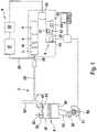
- the determination device serves to determine oil emissions, more generally for determining unburned hydrocarbon (HC) emissions originating from an internal combustion engine.
- the exemplary embodiment shown is an internal combustion engine 9 based on the reciprocating piston principle, but the exemplary embodiment of the invention is not limited to this.
- the motor 9 comprises at least one cylinder 90 in which a piston 94 is guided so that it can move up and down.
- a combustion chamber 91 is formed above the piston, to which fresh gas is supplied via a valve 92 and from which exhaust gas is discharged via a valve 92' into an exhaust pipe 92".
- the piston 94 is connected via a connecting rod 95 to a crank pin 96 of a crankshaft 97.
- An angle sensor 98 is arranged on the crankshaft 97 and outputs a measurement signal for crankshaft position and speed.
- the internal combustion engine 9 is designed conventionally, so that a detailed description can be dispensed with.
- it has an exhaust gas probe 1 on the exhaust pipe 92", to which a transfer capillary 2 is connected and which is connected to a filter device 4 and a measuring device 5.
- the exhaust gas probe 1 leads through the wall of the cylinder head.
- An inlet of the transfer capillary 2 is connected to an area with a wide diameter.
- the transfer capillary 2 has a droplet catching device 22 at its front tip 21, with which it is connected to the exhaust gas pipe 92''.
- This consists of a throttle section arranged directly in the opening 23, which has baffles 24 projecting obliquely at an angle of about 45° counter to the direction of flow.
- the baffles 24 are shaped to match the inner shape of the transfer capillary 2, ie they have the shape of a truncated cone shell overall in the case of a circular transfer capillary 2.
- Typical values for the diameter of the transfer capillary 2 are 0.5-2 mm, while in the throttle section 23 of the droplet catching device 22 the diameter is narrowed to 0.2-0.5 mm.
- the main area of the transfer capillary 2 extends as a tube-like transfer section, which has a pressure stage 25 with an enlarged tube diameter in its rear area. This is about 2-6 mm.
- a restriction capillary 26 is connected to the rear end of the pressure stage 25 and leads to an input connection of the filter and measuring device 4 , 5 .
- the restriction capillary 26 has a considerably smaller diameter of 50-500 ⁇ m. This reduction in cross-section results in a division of the mass flow and decoupling in terms of pressure.
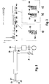
- the remaining mass flow is discharged to a vacuum pump 27, which is also connected to the rear end of the pressure stage 25 via an upstream vacuum tank 28 (see Fig. 2 ). With a pressure controller 29, a desired negative pressure with the pressure stage 25 and in the transfer capillary 2 is maintained.
- the amount of sample carried on from the restriction capillary 26 to the measurement channel is first fed to an ion source device 3 before it reaches the filter device 4 .
- This is designed to ionize the inflowing amount of gas. It is available, for example, as an ionizer based on the SMB (Supersonic Molecular Beam) principle. executed.
- the filter device 4 is arranged directly downstream of the ion source 3 in the direction of flow.
- a setting device 41 is assigned to it, on which a mass range can be set that is to be let through by the filter device 4 .
- the filter device 4 thus functions as a mass filter which only allows ions to pass in a desired passband of the mass spectrum and filters out the others.
- the filter device 4 can be designed as a quadrupole filter, for example. The construction of quadrupole filters in general is known in the prior art and does not need to be explained further here.
- the measuring device 5 is arranged further downstream of the filter device 4 in the direction of flow.
- the measuring device 5 includes a detector and a mass separator. This measuring device enables a broadband, quasi-simultaneous measurement of the intensity distribution of the ions over the specified passband.
- the measurement signal obtained in this way is an intensity sequence signal and is transmitted to an analysis device 6 .
- the measuring device 5 is capable of capturing the complete spectrum over the desired passband by fast scanning with high dynamics and resolution.
- the analysis device 6 includes a classifier 61 which interacts with a calibrator 62 .
- the calibrator 62 includes a first memory 63 and a second memory 64.
- the first memory 63 contains reference data on the spectral distribution of vaporous oil components and the second memory 64 contains reference data on the spectral mass distribution of droplet-shaped oil components.
- the classifier 61 can thus be be set so that it differentiates and evaluates the vaporous oil components on the one hand and the droplet-shaped oil components on the other hand in the measurement results of the measuring device 5 .
- sub-fields are preferably provided for distinguishing between vaporous and droplet-shaped oil components.
- Such a subfield is in figure 3 shown in the illustration above.
- Two subfields are shown with dashed lines, a larger one (in the range 170-380 m/z) and a smaller one (in the range 170-270 m/z). It should be noted that in this case the subfields overlap, but they can also be separate from each other.
- the small sub-field stands for the volatile fraction, while the large sub-field stands for the sum of the volatile and non-volatile fractions.
- a matched filter 65 is expediently provided for evaluation, in particular with weighting of various adjustable fields or sub-fields. It forms part of the classifier 61 and also interacts with the calibrator 62 in order to assign the determined mass spectra to predetermined formation mechanisms, taking into account the intensity sequences. This can be used, for example, to determine whether the measured lubricating oil emissions are based on simple evaporation or on mechanical processes, such as scraping or throwing off the oil from the inner wall of the cylinder 90. This is an example of a type of lubricating oil using FIG Figure 3ac explained (in other cases, deviating mass limits may arise).
- the lubricating oil emission is broader in the spectrum and extends beyond molecular ions with a specific charge of more than 350 m/z (see the sub-panel surrounded by the black dashed line). If the oil is thrown off, especially on the piston rings of the piston 94 (see Fig. 3 c) something similar is explained in principle: Here, too, both highly volatile and non-volatile lubricating oil fractions get into the exhaust gas and are then recorded as lubricating oil emissions. By correlating the proportions of highly volatile lubricating oil fractions compared to highly volatile and non-volatile lubricating oil fractions, a statement can even be made about the type of formation mechanism. This is done automatically using the matched filter.
- the determination device also has a further measurement branch 8 for determining combustion residues. It comprises a mass spectrometer 81, known per se, with a connected measuring device 82. This transmits the measurement data obtained to an interface module 68 of the analysis device 6.
- the analysis device 6 can thus also process data on burnt oil components during the evaluation consider. On the one hand, this enables a more comprehensive measurement result and thus an overview of the total emissions of the oil, whether burned or unburned. On the other hand, the oil emission mechanism can thus be determined more precisely, since oil vapors in particular often result in at least partial combustion of the oil emission, which is thus recorded thanks to the additional measuring branch 8 and taken into account by means of the interface 68 in the further evaluation.
- the second measuring branch 8 is connected to the transfer capillary 2 via a second measuring channel 28 .
- a totalizer 67 is also provided. This serves to form an overall value based on the measured values from the measuring device 6 for the unburned hydrocarbon emissions and the measured values originating from the interface 68 for the burnt oil emissions.
- the negative pressure pump 27 and the pressure controller 29 are preferably designed to generate a negative pressure of approximately 0.3 bar absolute. Due to the geometric conditions in the transfer capillary 2 with the pressure stage 25 and the line 22, a pressure curve results as shown in figure 4 a is shown. Next is in with dashed line figure 4 a shows the flow velocity that occurs in the transfer capillary 2 at the respective points during the pressure curve. It can be seen that with the appropriately set pressure at the throttle section 23 of the droplet catching device 22, a very high flow rate of approximately 150 m/s is achieved. This is a significant increase over known prior art exhaust gas probes which a comparison image in Figure 4b is shown.
Landscapes
- Chemical & Material Sciences (AREA)
- Engineering & Computer Science (AREA)
- Life Sciences & Earth Sciences (AREA)
- Health & Medical Sciences (AREA)
- Analytical Chemistry (AREA)
- General Physics & Mathematics (AREA)
- Physics & Mathematics (AREA)
- Biochemistry (AREA)
- General Health & Medical Sciences (AREA)
- Immunology (AREA)
- Pathology (AREA)
- Food Science & Technology (AREA)
- Medicinal Chemistry (AREA)
- Chemical Kinetics & Catalysis (AREA)
- General Chemical & Material Sciences (AREA)
- Oil, Petroleum & Natural Gas (AREA)
- Combustion & Propulsion (AREA)
- Biomedical Technology (AREA)
- Molecular Biology (AREA)
- Other Investigation Or Analysis Of Materials By Electrical Means (AREA)
- Sampling And Sample Adjustment (AREA)
- Testing Of Engines (AREA)
Applications Claiming Priority (2)
| Application Number | Priority Date | Filing Date | Title |
|---|---|---|---|
| DE201310218930 DE102013218930A1 (de) | 2013-09-20 | 2013-09-20 | Mehrfach-Ölemissionsmessgerät für Motoren |
| PCT/EP2014/069919 WO2015040124A1 (de) | 2013-09-20 | 2014-09-18 | Mehrfach-ölemissionsmessgerät für motoren |
Publications (2)
| Publication Number | Publication Date |
|---|---|
| EP3047515A1 EP3047515A1 (de) | 2016-07-27 |
| EP3047515B1 true EP3047515B1 (de) | 2022-11-02 |
Family
ID=51619156
Family Applications (1)
| Application Number | Title | Priority Date | Filing Date |
|---|---|---|---|
| EP14772309.2A Active EP3047515B1 (de) | 2013-09-20 | 2014-09-18 | Mehrfach-ölemissionsmessgerät für motoren |
Country Status (5)
| Country | Link |
|---|---|
| US (1) | US10020175B2 (enExample) |
| EP (1) | EP3047515B1 (enExample) |
| JP (1) | JP6474416B2 (enExample) |
| DE (1) | DE102013218930A1 (enExample) |
| WO (1) | WO2015040124A1 (enExample) |
Families Citing this family (2)
| Publication number | Priority date | Publication date | Assignee | Title |
|---|---|---|---|---|
| CN105067266B (zh) * | 2015-07-29 | 2017-11-14 | 华中科技大学 | 一种适用于燃气轮机的多功能燃烧室实验系统 |
| AT518184B1 (de) * | 2016-01-21 | 2017-08-15 | Avl List Gmbh | Messgas Entnahmeeinrichtung |
Family Cites Families (26)
| Publication number | Priority date | Publication date | Assignee | Title |
|---|---|---|---|---|
| DE2438810A1 (de) * | 1974-08-13 | 1976-03-04 | Battelle Institut E V | Messgeraet zur kontinuierlichen messung von organischen chlorverbindungen und von kohlenwasserstoffen |
| GB9010563D0 (en) * | 1990-05-11 | 1990-07-04 | Bottoms Ivan P | Removal of contaminants from exhaust gases from a frying vessel |
| EP0577543B1 (de) * | 1992-07-03 | 1995-12-13 | New Sulzer Diesel AG | Verfahren und Anlage zum Reinigen des einen Grossdieselmotor verlassenden Abgases |
| JPH10214590A (ja) * | 1997-01-31 | 1998-08-11 | Hitachi Ltd | 試料分析方法および装置 |
| US6273478B1 (en) * | 1999-03-30 | 2001-08-14 | The Regents Of The University Of California | Microfluidic interconnects |
| US7372043B2 (en) * | 2002-02-22 | 2008-05-13 | Agilent Technologies, Inc. | Apparatus and method for ion production enhancement |
| JP4555820B2 (ja) * | 2003-02-10 | 2010-10-06 | ウオーターズ・テクノロジーズ・コーポレイシヨン | シリコン上の脱離/イオン化質量分析(dios−ms)を使用した周囲空気の成分の吸着、検出、および同定 |
| DE102004001514A1 (de) * | 2004-01-09 | 2005-08-04 | Marcus Dr.-Ing. Gohl | Verfahren und Vorrichtung zur Bestimmung des Schmierölgehalts in einem Abgasgemisch |
| JP4407927B2 (ja) * | 2004-08-10 | 2010-02-03 | 正司 香月 | 蒸気濃度計測方法 |
| EP1707267A1 (en) * | 2005-03-30 | 2006-10-04 | F. Hoffman-la Roche AG | Device having a self sealing fluid port |
| US7642510B2 (en) * | 2006-08-22 | 2010-01-05 | E.I. Du Pont De Nemours And Company | Ion source for a mass spectrometer |
| US8969795B2 (en) * | 2008-10-06 | 2015-03-03 | Shimadzu Corporation | Curtain gas filter for mass- and mobility-analyzers that excludes ion-source gases and ions of high mobility |
| DE102009020360A1 (de) * | 2009-04-30 | 2010-11-04 | Iav Gmbh Ingenieurgesellschaft Auto Und Verkehr | Vorrichtung und Verfahren zur Bestimmung des Schmierölgehaltes in einem Abgasgemisch |
| IT1400850B1 (it) * | 2009-07-08 | 2013-07-02 | Varian Spa | Apparecchiatura di analisi gc-ms. |
| DE102010012606A1 (de) | 2010-03-24 | 2011-09-29 | Tutech Innovation Gmbh | Analyseeinrichtung für Abgase, insbesondere von Verbrennungsmotoren |
| CN103370615A (zh) * | 2010-10-25 | 2013-10-23 | 华盛顿大学商业中心 | 同时寻找和测定复杂样品中的多种分析物的方法及系统 |
| JP5802566B2 (ja) * | 2012-01-23 | 2015-10-28 | 株式会社日立ハイテクノロジーズ | 質量分析装置 |
| US8664593B2 (en) * | 2012-05-18 | 2014-03-04 | Thermo Finnigan Llc | Control of gas flow in high field asymmetric waveform ion mobility spectrometry |
| GB201216412D0 (en) * | 2012-09-14 | 2012-10-31 | Shimadzu Corp | Apparatus for providing gaseous sample ions/molecules and a corresponding method |
| JP5893756B2 (ja) * | 2012-11-29 | 2016-03-23 | 株式会社日立ハイテクノロジーズ | ハイブリッドイオン源、質量分析計及びイオンモビリティ装置 |
| US8907275B1 (en) * | 2013-05-20 | 2014-12-09 | Sociedad Europea de Analisis Diferencial de Movilidad | Method and apparatus to improve the separation capacity in a sequence of ion filters incorporating at least two ion mobility analyzers |
| DE202013005959U1 (de) * | 2013-07-03 | 2014-10-06 | Manfred Gohl | Bestimmungsvorrichtung für Kohlenwasserstoff-Emissionen von Motoren |
| JP2015032463A (ja) * | 2013-08-02 | 2015-02-16 | キヤノン株式会社 | 質量分析装置、質量分析方法および画像化システム |
| JP6423878B2 (ja) * | 2013-08-07 | 2018-11-14 | ディーエイチ テクノロジーズ デベロップメント プライベート リミテッド | 液体サンプルのための増大された噴霧形成 |
| US9390901B2 (en) * | 2014-10-31 | 2016-07-12 | Ut-Battelle, Llc | System and method for liquid extraction electrospray-assisted sample transfer to solution for chemical analysis |
| US9852896B2 (en) * | 2015-05-05 | 2017-12-26 | Ohio State Innovation Foundation | Method and apparatus for contained-electrospray for use in mass spectrometry and droplet reactions |
-
2013
- 2013-09-20 DE DE201310218930 patent/DE102013218930A1/de not_active Ceased
-
2014
- 2014-09-18 EP EP14772309.2A patent/EP3047515B1/de active Active
- 2014-09-18 JP JP2016543403A patent/JP6474416B2/ja active Active
- 2014-09-18 WO PCT/EP2014/069919 patent/WO2015040124A1/de not_active Ceased
- 2014-09-18 US US15/023,638 patent/US10020175B2/en active Active
Also Published As
| Publication number | Publication date |
|---|---|
| EP3047515A1 (de) | 2016-07-27 |
| US20160211127A1 (en) | 2016-07-21 |
| US10020175B2 (en) | 2018-07-10 |
| WO2015040124A1 (de) | 2015-03-26 |
| JP6474416B2 (ja) | 2019-02-27 |
| JP2016534367A (ja) | 2016-11-04 |
| DE102013218930A1 (de) | 2015-04-16 |
Similar Documents
| Publication | Publication Date | Title |
|---|---|---|
| EP2270465B1 (de) | Verfahren und Vorrichtung zur Detektion, Charakterisierung und/oder Elimination von Schwebeteilchen | |
| DE2509411A1 (de) | Verfahren und vorrichtung zur durchfuehrung der abgas-analyse an verbrennungsmotoren von kraftfahrzeugen | |
| DE10218218A1 (de) | Vorrichtung und Verfahren zur Feststellung einer Fehlfunktion eines Filters | |
| DE102012200062A1 (de) | Brennkraftmaschine mit im Luftansaugtrakt angeordnetem Sauerstoffsensor und Sauerstoffsensor | |
| EP3047515B1 (de) | Mehrfach-ölemissionsmessgerät für motoren | |
| DE102016221502A1 (de) | Abgassensor | |
| DE102009045376A1 (de) | Verfahren und Vorrichtung zur Diagnose der Dynamik eines Abgassensors | |
| DE102006006112B4 (de) | Partikelsensor | |
| EP3017459B1 (de) | Bestimmungsvorrichtung für kohlenwasserstoff-emissionen von motoren | |
| DE202008014667U1 (de) | Messgerät | |
| DE102004025208B4 (de) | Verfahren zur Bestimmung charakteristischer Eigenschaften von Rußpartikeln | |
| EP3112845B1 (de) | Vorrichtung zur optischen in-situ analyse eines messgases | |
| DE102009025183B4 (de) | Verfahren und Vorrichtung zur Bestimmung der Staub- und Rußpartikelkonzentration | |
| EP0523822A2 (de) | Verfahren zur Untersuchung der Verbrennung in einem Verbrennungsmotor | |
| DE19523599A1 (de) | Verfahren und Vorrichtung zum Erfassen des Massenstromverlaufs mindestens einer Emissionskomponente eines Verbrennungsabgases | |
| DE102014219822A1 (de) | Brennkraftmaschine und Verfahren zum Bewerten der Ölqualität in einer Brennkraftmaschine | |
| DE102010012606A1 (de) | Analyseeinrichtung für Abgase, insbesondere von Verbrennungsmotoren | |
| DE102013012398A1 (de) | Verfahren zum Betreiben einer Brennkraftmaschine | |
| AT515726A1 (de) | Vorrichtung zum ortsaufgelösten erfassen und/oder extrahieren von zumindest einer gaskomponente in einem strömenden gas | |
| DE102021002264A1 (de) | Verbrennungskraftmaschine sowie Verfahren zum Ermitteln eines Kraftstoffeintrags in Öl einer solchen Verbrennungskraftmaschine | |
| DE102004057718B4 (de) | Vorrichtung zur Analyse von Strömungsvorgängen in der Kolbenmulde einer Brennkraftmaschine | |
| DE102018222766A1 (de) | Verfahren zum Erkennen eines Defekts in einer Kurbelgehäuseentlüftung | |
| DE102004052743A1 (de) | Messsystem zur Analyse eines Kraftstoff-Luft-Gemisches in einem Motorbrennraum | |
| DE102005034454A1 (de) | Verfahren zur Messung des Verbrauchs zumindest eines Betriebsmittels einer Kraft- oder Arbeitsmaschine | |
| DE102018105335B3 (de) | Verfahren und Vorrichtung zur Bestimmung des Gehalts an Schmiermittel in dem Abgas einer Verbrennungskraftmaschine |
Legal Events
| Date | Code | Title | Description |
|---|---|---|---|
| PUAI | Public reference made under article 153(3) epc to a published international application that has entered the european phase |
Free format text: ORIGINAL CODE: 0009012 |
|
| 17P | Request for examination filed |
Effective date: 20160419 |
|
| AK | Designated contracting states |
Kind code of ref document: A1 Designated state(s): AL AT BE BG CH CY CZ DE DK EE ES FI FR GB GR HR HU IE IS IT LI LT LU LV MC MK MT NL NO PL PT RO RS SE SI SK SM TR |
|
| AX | Request for extension of the european patent |
Extension state: BA ME |
|
| DAX | Request for extension of the european patent (deleted) | ||
| STAA | Information on the status of an ep patent application or granted ep patent |
Free format text: STATUS: EXAMINATION IS IN PROGRESS |
|
| 17Q | First examination report despatched |
Effective date: 20190529 |
|
| RAP1 | Party data changed (applicant data changed or rights of an application transferred) |
Owner name: LUBRISENSE GMBH |
|
| REG | Reference to a national code |
Ref country code: DE Ref legal event code: R079 Ref document number: 502014016426 Country of ref document: DE Free format text: PREVIOUS MAIN CLASS: H01J0049260000 Ipc: G01N0033280000 |
|
| RIC1 | Information provided on ipc code assigned before grant |
Ipc: G01M 15/10 20060101ALI20220325BHEP Ipc: G01N 1/22 20060101ALI20220325BHEP Ipc: G01N 33/28 20060101AFI20220325BHEP |
|
| GRAP | Despatch of communication of intention to grant a patent |
Free format text: ORIGINAL CODE: EPIDOSNIGR1 |
|
| STAA | Information on the status of an ep patent application or granted ep patent |
Free format text: STATUS: GRANT OF PATENT IS INTENDED |
|
| INTG | Intention to grant announced |
Effective date: 20220520 |
|
| GRAS | Grant fee paid |
Free format text: ORIGINAL CODE: EPIDOSNIGR3 |
|
| GRAA | (expected) grant |
Free format text: ORIGINAL CODE: 0009210 |
|
| STAA | Information on the status of an ep patent application or granted ep patent |
Free format text: STATUS: THE PATENT HAS BEEN GRANTED |
|
| AK | Designated contracting states |
Kind code of ref document: B1 Designated state(s): AL AT BE BG CH CY CZ DE DK EE ES FI FR GB GR HR HU IE IS IT LI LT LU LV MC MK MT NL NO PL PT RO RS SE SI SK SM TR |
|
| REG | Reference to a national code |
Ref country code: GB Ref legal event code: FG4D Free format text: NOT ENGLISH |
|
| REG | Reference to a national code |
Ref country code: CH Ref legal event code: EP Ref country code: AT Ref legal event code: REF Ref document number: 1529104 Country of ref document: AT Kind code of ref document: T Effective date: 20221115 |
|
| REG | Reference to a national code |
Ref country code: DE Ref legal event code: R096 Ref document number: 502014016426 Country of ref document: DE |
|
| REG | Reference to a national code |
Ref country code: IE Ref legal event code: FG4D Free format text: LANGUAGE OF EP DOCUMENT: GERMAN |
|
| REG | Reference to a national code |
Ref country code: LT Ref legal event code: MG9D |
|
| REG | Reference to a national code |
Ref country code: NL Ref legal event code: MP Effective date: 20221102 |
|
| PG25 | Lapsed in a contracting state [announced via postgrant information from national office to epo] |
Ref country code: SE Free format text: LAPSE BECAUSE OF FAILURE TO SUBMIT A TRANSLATION OF THE DESCRIPTION OR TO PAY THE FEE WITHIN THE PRESCRIBED TIME-LIMIT Effective date: 20221102 Ref country code: PT Free format text: LAPSE BECAUSE OF FAILURE TO SUBMIT A TRANSLATION OF THE DESCRIPTION OR TO PAY THE FEE WITHIN THE PRESCRIBED TIME-LIMIT Effective date: 20230302 Ref country code: NO Free format text: LAPSE BECAUSE OF FAILURE TO SUBMIT A TRANSLATION OF THE DESCRIPTION OR TO PAY THE FEE WITHIN THE PRESCRIBED TIME-LIMIT Effective date: 20230202 Ref country code: LT Free format text: LAPSE BECAUSE OF FAILURE TO SUBMIT A TRANSLATION OF THE DESCRIPTION OR TO PAY THE FEE WITHIN THE PRESCRIBED TIME-LIMIT Effective date: 20221102 Ref country code: FI Free format text: LAPSE BECAUSE OF FAILURE TO SUBMIT A TRANSLATION OF THE DESCRIPTION OR TO PAY THE FEE WITHIN THE PRESCRIBED TIME-LIMIT Effective date: 20221102 Ref country code: ES Free format text: LAPSE BECAUSE OF FAILURE TO SUBMIT A TRANSLATION OF THE DESCRIPTION OR TO PAY THE FEE WITHIN THE PRESCRIBED TIME-LIMIT Effective date: 20221102 |
|
| PG25 | Lapsed in a contracting state [announced via postgrant information from national office to epo] |
Ref country code: RS Free format text: LAPSE BECAUSE OF FAILURE TO SUBMIT A TRANSLATION OF THE DESCRIPTION OR TO PAY THE FEE WITHIN THE PRESCRIBED TIME-LIMIT Effective date: 20221102 Ref country code: PL Free format text: LAPSE BECAUSE OF FAILURE TO SUBMIT A TRANSLATION OF THE DESCRIPTION OR TO PAY THE FEE WITHIN THE PRESCRIBED TIME-LIMIT Effective date: 20221102 Ref country code: LV Free format text: LAPSE BECAUSE OF FAILURE TO SUBMIT A TRANSLATION OF THE DESCRIPTION OR TO PAY THE FEE WITHIN THE PRESCRIBED TIME-LIMIT Effective date: 20221102 Ref country code: IS Free format text: LAPSE BECAUSE OF FAILURE TO SUBMIT A TRANSLATION OF THE DESCRIPTION OR TO PAY THE FEE WITHIN THE PRESCRIBED TIME-LIMIT Effective date: 20230302 Ref country code: HR Free format text: LAPSE BECAUSE OF FAILURE TO SUBMIT A TRANSLATION OF THE DESCRIPTION OR TO PAY THE FEE WITHIN THE PRESCRIBED TIME-LIMIT Effective date: 20221102 Ref country code: GR Free format text: LAPSE BECAUSE OF FAILURE TO SUBMIT A TRANSLATION OF THE DESCRIPTION OR TO PAY THE FEE WITHIN THE PRESCRIBED TIME-LIMIT Effective date: 20230203 |
|
| PG25 | Lapsed in a contracting state [announced via postgrant information from national office to epo] |
Ref country code: NL Free format text: LAPSE BECAUSE OF FAILURE TO SUBMIT A TRANSLATION OF THE DESCRIPTION OR TO PAY THE FEE WITHIN THE PRESCRIBED TIME-LIMIT Effective date: 20221102 |
|
| PG25 | Lapsed in a contracting state [announced via postgrant information from national office to epo] |
Ref country code: SM Free format text: LAPSE BECAUSE OF FAILURE TO SUBMIT A TRANSLATION OF THE DESCRIPTION OR TO PAY THE FEE WITHIN THE PRESCRIBED TIME-LIMIT Effective date: 20221102 Ref country code: RO Free format text: LAPSE BECAUSE OF FAILURE TO SUBMIT A TRANSLATION OF THE DESCRIPTION OR TO PAY THE FEE WITHIN THE PRESCRIBED TIME-LIMIT Effective date: 20221102 Ref country code: EE Free format text: LAPSE BECAUSE OF FAILURE TO SUBMIT A TRANSLATION OF THE DESCRIPTION OR TO PAY THE FEE WITHIN THE PRESCRIBED TIME-LIMIT Effective date: 20221102 Ref country code: DK Free format text: LAPSE BECAUSE OF FAILURE TO SUBMIT A TRANSLATION OF THE DESCRIPTION OR TO PAY THE FEE WITHIN THE PRESCRIBED TIME-LIMIT Effective date: 20221102 Ref country code: CZ Free format text: LAPSE BECAUSE OF FAILURE TO SUBMIT A TRANSLATION OF THE DESCRIPTION OR TO PAY THE FEE WITHIN THE PRESCRIBED TIME-LIMIT Effective date: 20221102 |
|
| REG | Reference to a national code |
Ref country code: DE Ref legal event code: R097 Ref document number: 502014016426 Country of ref document: DE |
|
| PG25 | Lapsed in a contracting state [announced via postgrant information from national office to epo] |
Ref country code: SK Free format text: LAPSE BECAUSE OF FAILURE TO SUBMIT A TRANSLATION OF THE DESCRIPTION OR TO PAY THE FEE WITHIN THE PRESCRIBED TIME-LIMIT Effective date: 20221102 Ref country code: AL Free format text: LAPSE BECAUSE OF FAILURE TO SUBMIT A TRANSLATION OF THE DESCRIPTION OR TO PAY THE FEE WITHIN THE PRESCRIBED TIME-LIMIT Effective date: 20221102 |
|
| PLBE | No opposition filed within time limit |
Free format text: ORIGINAL CODE: 0009261 |
|
| STAA | Information on the status of an ep patent application or granted ep patent |
Free format text: STATUS: NO OPPOSITION FILED WITHIN TIME LIMIT |
|
| 26N | No opposition filed |
Effective date: 20230803 |
|
| PG25 | Lapsed in a contracting state [announced via postgrant information from national office to epo] |
Ref country code: SI Free format text: LAPSE BECAUSE OF FAILURE TO SUBMIT A TRANSLATION OF THE DESCRIPTION OR TO PAY THE FEE WITHIN THE PRESCRIBED TIME-LIMIT Effective date: 20221102 |
|
| REG | Reference to a national code |
Ref country code: CH Ref legal event code: PL |
|
| PG25 | Lapsed in a contracting state [announced via postgrant information from national office to epo] |
Ref country code: LU Free format text: LAPSE BECAUSE OF NON-PAYMENT OF DUE FEES Effective date: 20230918 |
|
| REG | Reference to a national code |
Ref country code: BE Ref legal event code: MM Effective date: 20230930 |
|
| GBPC | Gb: european patent ceased through non-payment of renewal fee |
Effective date: 20230918 |
|
| PG25 | Lapsed in a contracting state [announced via postgrant information from national office to epo] |
Ref country code: LU Free format text: LAPSE BECAUSE OF NON-PAYMENT OF DUE FEES Effective date: 20230918 Ref country code: IT Free format text: LAPSE BECAUSE OF FAILURE TO SUBMIT A TRANSLATION OF THE DESCRIPTION OR TO PAY THE FEE WITHIN THE PRESCRIBED TIME-LIMIT Effective date: 20221102 Ref country code: MC Free format text: LAPSE BECAUSE OF FAILURE TO SUBMIT A TRANSLATION OF THE DESCRIPTION OR TO PAY THE FEE WITHIN THE PRESCRIBED TIME-LIMIT Effective date: 20221102 |
|
| REG | Reference to a national code |
Ref country code: IE Ref legal event code: MM4A |
|
| PG25 | Lapsed in a contracting state [announced via postgrant information from national office to epo] |
Ref country code: IE Free format text: LAPSE BECAUSE OF NON-PAYMENT OF DUE FEES Effective date: 20230918 |
|
| PG25 | Lapsed in a contracting state [announced via postgrant information from national office to epo] |
Ref country code: GB Free format text: LAPSE BECAUSE OF NON-PAYMENT OF DUE FEES Effective date: 20230918 |
|
| PG25 | Lapsed in a contracting state [announced via postgrant information from national office to epo] |
Ref country code: CH Free format text: LAPSE BECAUSE OF NON-PAYMENT OF DUE FEES Effective date: 20230930 |
|
| PG25 | Lapsed in a contracting state [announced via postgrant information from national office to epo] |
Ref country code: IE Free format text: LAPSE BECAUSE OF NON-PAYMENT OF DUE FEES Effective date: 20230918 Ref country code: GB Free format text: LAPSE BECAUSE OF NON-PAYMENT OF DUE FEES Effective date: 20230918 Ref country code: FR Free format text: LAPSE BECAUSE OF NON-PAYMENT OF DUE FEES Effective date: 20230930 Ref country code: CH Free format text: LAPSE BECAUSE OF NON-PAYMENT OF DUE FEES Effective date: 20230930 |
|
| PG25 | Lapsed in a contracting state [announced via postgrant information from national office to epo] |
Ref country code: BE Free format text: LAPSE BECAUSE OF NON-PAYMENT OF DUE FEES Effective date: 20230930 |
|
| PGFP | Annual fee paid to national office [announced via postgrant information from national office to epo] |
Ref country code: DE Payment date: 20240924 Year of fee payment: 11 |
|
| PG25 | Lapsed in a contracting state [announced via postgrant information from national office to epo] |
Ref country code: BG Free format text: LAPSE BECAUSE OF FAILURE TO SUBMIT A TRANSLATION OF THE DESCRIPTION OR TO PAY THE FEE WITHIN THE PRESCRIBED TIME-LIMIT Effective date: 20221102 |
|
| REG | Reference to a national code |
Ref country code: AT Ref legal event code: MM01 Ref document number: 1529104 Country of ref document: AT Kind code of ref document: T Effective date: 20230918 |
|
| PG25 | Lapsed in a contracting state [announced via postgrant information from national office to epo] |
Ref country code: BG Free format text: LAPSE BECAUSE OF FAILURE TO SUBMIT A TRANSLATION OF THE DESCRIPTION OR TO PAY THE FEE WITHIN THE PRESCRIBED TIME-LIMIT Effective date: 20221102 |
|
| PG25 | Lapsed in a contracting state [announced via postgrant information from national office to epo] |
Ref country code: AT Free format text: LAPSE BECAUSE OF NON-PAYMENT OF DUE FEES Effective date: 20230918 |
|
| PG25 | Lapsed in a contracting state [announced via postgrant information from national office to epo] |
Ref country code: AT Free format text: LAPSE BECAUSE OF NON-PAYMENT OF DUE FEES Effective date: 20230918 |
|
| PG25 | Lapsed in a contracting state [announced via postgrant information from national office to epo] |
Ref country code: CY Free format text: LAPSE BECAUSE OF FAILURE TO SUBMIT A TRANSLATION OF THE DESCRIPTION OR TO PAY THE FEE WITHIN THE PRESCRIBED TIME-LIMIT; INVALID AB INITIO Effective date: 20140918 |
|
| PG25 | Lapsed in a contracting state [announced via postgrant information from national office to epo] |
Ref country code: HU Free format text: LAPSE BECAUSE OF FAILURE TO SUBMIT A TRANSLATION OF THE DESCRIPTION OR TO PAY THE FEE WITHIN THE PRESCRIBED TIME-LIMIT; INVALID AB INITIO Effective date: 20140918 |