EP3045962A1 - Dispositif d'affichage et son procédé de fabrication - Google Patents
Dispositif d'affichage et son procédé de fabrication Download PDFInfo
- Publication number
- EP3045962A1 EP3045962A1 EP15189758.4A EP15189758A EP3045962A1 EP 3045962 A1 EP3045962 A1 EP 3045962A1 EP 15189758 A EP15189758 A EP 15189758A EP 3045962 A1 EP3045962 A1 EP 3045962A1
- Authority
- EP
- European Patent Office
- Prior art keywords
- color filter
- data line
- disposed
- display device
- dummy
- Prior art date
- Legal status (The legal status is an assumption and is not a legal conclusion. Google has not performed a legal analysis and makes no representation as to the accuracy of the status listed.)
- Granted
Links
- 238000004519 manufacturing process Methods 0.000 title claims description 39
- 239000000758 substrate Substances 0.000 claims abstract description 25
- 239000000463 material Substances 0.000 claims description 31
- 238000000034 method Methods 0.000 claims description 31
- 239000011248 coating agent Substances 0.000 claims description 6
- 238000000576 coating method Methods 0.000 claims description 6
- 239000004973 liquid crystal related substance Substances 0.000 description 33
- 230000008569 process Effects 0.000 description 29
- 230000003071 parasitic effect Effects 0.000 description 22
- 239000010408 film Substances 0.000 description 19
- 239000004020 conductor Substances 0.000 description 15
- 230000000903 blocking effect Effects 0.000 description 14
- 239000013067 intermediate product Substances 0.000 description 12
- 239000010409 thin film Substances 0.000 description 12
- 239000003086 colorant Substances 0.000 description 11
- 239000004065 semiconductor Substances 0.000 description 11
- 238000002834 transmittance Methods 0.000 description 11
- 230000005684 electric field Effects 0.000 description 10
- 238000000206 photolithography Methods 0.000 description 10
- 229910052751 metal Inorganic materials 0.000 description 8
- 239000002184 metal Substances 0.000 description 8
- 239000011368 organic material Substances 0.000 description 8
- 230000008878 coupling Effects 0.000 description 7
- 238000010168 coupling process Methods 0.000 description 7
- 238000005859 coupling reaction Methods 0.000 description 7
- ZOKXTWBITQBERF-UHFFFAOYSA-N Molybdenum Chemical compound [Mo] ZOKXTWBITQBERF-UHFFFAOYSA-N 0.000 description 6
- 229910045601 alloy Inorganic materials 0.000 description 6
- 239000000956 alloy Substances 0.000 description 6
- 229910052750 molybdenum Inorganic materials 0.000 description 6
- 239000011733 molybdenum Substances 0.000 description 6
- 229910052782 aluminium Inorganic materials 0.000 description 4
- XAGFODPZIPBFFR-UHFFFAOYSA-N aluminium Chemical compound [Al] XAGFODPZIPBFFR-UHFFFAOYSA-N 0.000 description 4
- 239000011651 chromium Substances 0.000 description 4
- 230000000694 effects Effects 0.000 description 4
- VYZAMTAEIAYCRO-UHFFFAOYSA-N Chromium Chemical compound [Cr] VYZAMTAEIAYCRO-UHFFFAOYSA-N 0.000 description 3
- 230000009471 action Effects 0.000 description 3
- 229910052804 chromium Inorganic materials 0.000 description 3
- 239000010949 copper Substances 0.000 description 3
- 230000003247 decreasing effect Effects 0.000 description 3
- 238000002513 implantation Methods 0.000 description 3
- 239000011810 insulating material Substances 0.000 description 3
- 239000011159 matrix material Substances 0.000 description 3
- 239000000049 pigment Substances 0.000 description 3
- 125000006850 spacer group Chemical group 0.000 description 3
- 239000010936 titanium Substances 0.000 description 3
- RYGMFSIKBFXOCR-UHFFFAOYSA-N Copper Chemical compound [Cu] RYGMFSIKBFXOCR-UHFFFAOYSA-N 0.000 description 2
- 206010034972 Photosensitivity reaction Diseases 0.000 description 2
- VYPSYNLAJGMNEJ-UHFFFAOYSA-N Silicium dioxide Chemical compound O=[Si]=O VYPSYNLAJGMNEJ-UHFFFAOYSA-N 0.000 description 2
- BQCADISMDOOEFD-UHFFFAOYSA-N Silver Chemical compound [Ag] BQCADISMDOOEFD-UHFFFAOYSA-N 0.000 description 2
- RTAQQCXQSZGOHL-UHFFFAOYSA-N Titanium Chemical compound [Ti] RTAQQCXQSZGOHL-UHFFFAOYSA-N 0.000 description 2
- 229910021417 amorphous silicon Inorganic materials 0.000 description 2
- 239000000470 constituent Substances 0.000 description 2
- 229910052802 copper Inorganic materials 0.000 description 2
- 239000011521 glass Substances 0.000 description 2
- 239000012535 impurity Substances 0.000 description 2
- 150000002739 metals Chemical class 0.000 description 2
- 238000012986 modification Methods 0.000 description 2
- 230000004048 modification Effects 0.000 description 2
- 230000035515 penetration Effects 0.000 description 2
- 230000036211 photosensitivity Effects 0.000 description 2
- 230000000704 physical effect Effects 0.000 description 2
- 239000004033 plastic Substances 0.000 description 2
- 230000009467 reduction Effects 0.000 description 2
- 239000003870 refractory metal Substances 0.000 description 2
- 229910052814 silicon oxide Inorganic materials 0.000 description 2
- 229910052709 silver Inorganic materials 0.000 description 2
- 239000004332 silver Substances 0.000 description 2
- 229910052715 tantalum Inorganic materials 0.000 description 2
- GUVRBAGPIYLISA-UHFFFAOYSA-N tantalum atom Chemical compound [Ta] GUVRBAGPIYLISA-UHFFFAOYSA-N 0.000 description 2
- 229910052719 titanium Inorganic materials 0.000 description 2
- 229910001316 Ag alloy Inorganic materials 0.000 description 1
- 229910000838 Al alloy Inorganic materials 0.000 description 1
- 229910000881 Cu alloy Inorganic materials 0.000 description 1
- 229910001182 Mo alloy Inorganic materials 0.000 description 1
- 239000004988 Nematic liquid crystal Substances 0.000 description 1
- OAICVXFJPJFONN-UHFFFAOYSA-N Phosphorus Chemical compound [P] OAICVXFJPJFONN-UHFFFAOYSA-N 0.000 description 1
- 229910052581 Si3N4 Inorganic materials 0.000 description 1
- 229910004205 SiNX Inorganic materials 0.000 description 1
- 239000006229 carbon black Substances 0.000 description 1
- 230000008859 change Effects 0.000 description 1
- 238000011109 contamination Methods 0.000 description 1
- 230000006866 deterioration Effects 0.000 description 1
- 238000010586 diagram Methods 0.000 description 1
- 239000007943 implant Substances 0.000 description 1
- 229910052698 phosphorus Inorganic materials 0.000 description 1
- 239000011574 phosphorus Substances 0.000 description 1
- 230000010287 polarization Effects 0.000 description 1
- 229910021420 polycrystalline silicon Inorganic materials 0.000 description 1
- 229920005591 polysilicon Polymers 0.000 description 1
- 229910021332 silicide Inorganic materials 0.000 description 1
- FVBUAEGBCNSCDD-UHFFFAOYSA-N silicide(4-) Chemical compound [Si-4] FVBUAEGBCNSCDD-UHFFFAOYSA-N 0.000 description 1
- HQVNEWCFYHHQES-UHFFFAOYSA-N silicon nitride Chemical compound N12[Si]34N5[Si]62N3[Si]51N64 HQVNEWCFYHHQES-UHFFFAOYSA-N 0.000 description 1
Images


Classifications
-
- G—PHYSICS
- G02—OPTICS
- G02F—OPTICAL DEVICES OR ARRANGEMENTS FOR THE CONTROL OF LIGHT BY MODIFICATION OF THE OPTICAL PROPERTIES OF THE MEDIA OF THE ELEMENTS INVOLVED THEREIN; NON-LINEAR OPTICS; FREQUENCY-CHANGING OF LIGHT; OPTICAL LOGIC ELEMENTS; OPTICAL ANALOGUE/DIGITAL CONVERTERS
- G02F1/00—Devices or arrangements for the control of the intensity, colour, phase, polarisation or direction of light arriving from an independent light source, e.g. switching, gating or modulating; Non-linear optics
- G02F1/01—Devices or arrangements for the control of the intensity, colour, phase, polarisation or direction of light arriving from an independent light source, e.g. switching, gating or modulating; Non-linear optics for the control of the intensity, phase, polarisation or colour
- G02F1/13—Devices or arrangements for the control of the intensity, colour, phase, polarisation or direction of light arriving from an independent light source, e.g. switching, gating or modulating; Non-linear optics for the control of the intensity, phase, polarisation or colour based on liquid crystals, e.g. single liquid crystal display cells
- G02F1/133—Constructional arrangements; Operation of liquid crystal cells; Circuit arrangements
- G02F1/1333—Constructional arrangements; Manufacturing methods
- G02F1/1335—Structural association of cells with optical devices, e.g. polarisers or reflectors
- G02F1/133509—Filters, e.g. light shielding masks
- G02F1/133514—Colour filters
-
- G—PHYSICS
- G02—OPTICS
- G02F—OPTICAL DEVICES OR ARRANGEMENTS FOR THE CONTROL OF LIGHT BY MODIFICATION OF THE OPTICAL PROPERTIES OF THE MEDIA OF THE ELEMENTS INVOLVED THEREIN; NON-LINEAR OPTICS; FREQUENCY-CHANGING OF LIGHT; OPTICAL LOGIC ELEMENTS; OPTICAL ANALOGUE/DIGITAL CONVERTERS
- G02F1/00—Devices or arrangements for the control of the intensity, colour, phase, polarisation or direction of light arriving from an independent light source, e.g. switching, gating or modulating; Non-linear optics
- G02F1/01—Devices or arrangements for the control of the intensity, colour, phase, polarisation or direction of light arriving from an independent light source, e.g. switching, gating or modulating; Non-linear optics for the control of the intensity, phase, polarisation or colour
- G02F1/13—Devices or arrangements for the control of the intensity, colour, phase, polarisation or direction of light arriving from an independent light source, e.g. switching, gating or modulating; Non-linear optics for the control of the intensity, phase, polarisation or colour based on liquid crystals, e.g. single liquid crystal display cells
- G02F1/133—Constructional arrangements; Operation of liquid crystal cells; Circuit arrangements
- G02F1/136—Liquid crystal cells structurally associated with a semi-conducting layer or substrate, e.g. cells forming part of an integrated circuit
- G02F1/1362—Active matrix addressed cells
-
- G—PHYSICS
- G02—OPTICS
- G02B—OPTICAL ELEMENTS, SYSTEMS OR APPARATUS
- G02B5/00—Optical elements other than lenses
- G02B5/20—Filters
- G02B5/201—Filters in the form of arrays
-
- G—PHYSICS
- G02—OPTICS
- G02F—OPTICAL DEVICES OR ARRANGEMENTS FOR THE CONTROL OF LIGHT BY MODIFICATION OF THE OPTICAL PROPERTIES OF THE MEDIA OF THE ELEMENTS INVOLVED THEREIN; NON-LINEAR OPTICS; FREQUENCY-CHANGING OF LIGHT; OPTICAL LOGIC ELEMENTS; OPTICAL ANALOGUE/DIGITAL CONVERTERS
- G02F1/00—Devices or arrangements for the control of the intensity, colour, phase, polarisation or direction of light arriving from an independent light source, e.g. switching, gating or modulating; Non-linear optics
- G02F1/01—Devices or arrangements for the control of the intensity, colour, phase, polarisation or direction of light arriving from an independent light source, e.g. switching, gating or modulating; Non-linear optics for the control of the intensity, phase, polarisation or colour
- G02F1/13—Devices or arrangements for the control of the intensity, colour, phase, polarisation or direction of light arriving from an independent light source, e.g. switching, gating or modulating; Non-linear optics for the control of the intensity, phase, polarisation or colour based on liquid crystals, e.g. single liquid crystal display cells
- G02F1/133—Constructional arrangements; Operation of liquid crystal cells; Circuit arrangements
- G02F1/1333—Constructional arrangements; Manufacturing methods
- G02F1/1335—Structural association of cells with optical devices, e.g. polarisers or reflectors
- G02F1/133509—Filters, e.g. light shielding masks
- G02F1/133514—Colour filters
- G02F1/133516—Methods for their manufacture, e.g. printing, electro-deposition or photolithography
-
- G—PHYSICS
- G02—OPTICS
- G02F—OPTICAL DEVICES OR ARRANGEMENTS FOR THE CONTROL OF LIGHT BY MODIFICATION OF THE OPTICAL PROPERTIES OF THE MEDIA OF THE ELEMENTS INVOLVED THEREIN; NON-LINEAR OPTICS; FREQUENCY-CHANGING OF LIGHT; OPTICAL LOGIC ELEMENTS; OPTICAL ANALOGUE/DIGITAL CONVERTERS
- G02F1/00—Devices or arrangements for the control of the intensity, colour, phase, polarisation or direction of light arriving from an independent light source, e.g. switching, gating or modulating; Non-linear optics
- G02F1/01—Devices or arrangements for the control of the intensity, colour, phase, polarisation or direction of light arriving from an independent light source, e.g. switching, gating or modulating; Non-linear optics for the control of the intensity, phase, polarisation or colour
- G02F1/13—Devices or arrangements for the control of the intensity, colour, phase, polarisation or direction of light arriving from an independent light source, e.g. switching, gating or modulating; Non-linear optics for the control of the intensity, phase, polarisation or colour based on liquid crystals, e.g. single liquid crystal display cells
- G02F1/133—Constructional arrangements; Operation of liquid crystal cells; Circuit arrangements
- G02F1/1333—Constructional arrangements; Manufacturing methods
- G02F1/1343—Electrodes
- G02F1/134309—Electrodes characterised by their geometrical arrangement
- G02F1/134372—Electrodes characterised by their geometrical arrangement for fringe field switching [FFS] where the common electrode is not patterned
-
- G—PHYSICS
- G02—OPTICS
- G02F—OPTICAL DEVICES OR ARRANGEMENTS FOR THE CONTROL OF LIGHT BY MODIFICATION OF THE OPTICAL PROPERTIES OF THE MEDIA OF THE ELEMENTS INVOLVED THEREIN; NON-LINEAR OPTICS; FREQUENCY-CHANGING OF LIGHT; OPTICAL LOGIC ELEMENTS; OPTICAL ANALOGUE/DIGITAL CONVERTERS
- G02F1/00—Devices or arrangements for the control of the intensity, colour, phase, polarisation or direction of light arriving from an independent light source, e.g. switching, gating or modulating; Non-linear optics
- G02F1/01—Devices or arrangements for the control of the intensity, colour, phase, polarisation or direction of light arriving from an independent light source, e.g. switching, gating or modulating; Non-linear optics for the control of the intensity, phase, polarisation or colour
- G02F1/13—Devices or arrangements for the control of the intensity, colour, phase, polarisation or direction of light arriving from an independent light source, e.g. switching, gating or modulating; Non-linear optics for the control of the intensity, phase, polarisation or colour based on liquid crystals, e.g. single liquid crystal display cells
- G02F1/133—Constructional arrangements; Operation of liquid crystal cells; Circuit arrangements
- G02F1/136—Liquid crystal cells structurally associated with a semi-conducting layer or substrate, e.g. cells forming part of an integrated circuit
- G02F1/1362—Active matrix addressed cells
- G02F1/136222—Colour filters incorporated in the active matrix substrate
-
- G—PHYSICS
- G02—OPTICS
- G02F—OPTICAL DEVICES OR ARRANGEMENTS FOR THE CONTROL OF LIGHT BY MODIFICATION OF THE OPTICAL PROPERTIES OF THE MEDIA OF THE ELEMENTS INVOLVED THEREIN; NON-LINEAR OPTICS; FREQUENCY-CHANGING OF LIGHT; OPTICAL LOGIC ELEMENTS; OPTICAL ANALOGUE/DIGITAL CONVERTERS
- G02F1/00—Devices or arrangements for the control of the intensity, colour, phase, polarisation or direction of light arriving from an independent light source, e.g. switching, gating or modulating; Non-linear optics
- G02F1/01—Devices or arrangements for the control of the intensity, colour, phase, polarisation or direction of light arriving from an independent light source, e.g. switching, gating or modulating; Non-linear optics for the control of the intensity, phase, polarisation or colour
- G02F1/13—Devices or arrangements for the control of the intensity, colour, phase, polarisation or direction of light arriving from an independent light source, e.g. switching, gating or modulating; Non-linear optics for the control of the intensity, phase, polarisation or colour based on liquid crystals, e.g. single liquid crystal display cells
- G02F1/133—Constructional arrangements; Operation of liquid crystal cells; Circuit arrangements
- G02F1/136—Liquid crystal cells structurally associated with a semi-conducting layer or substrate, e.g. cells forming part of an integrated circuit
- G02F1/1362—Active matrix addressed cells
- G02F1/136286—Wiring, e.g. gate line, drain line
-
- G—PHYSICS
- G02—OPTICS
- G02F—OPTICAL DEVICES OR ARRANGEMENTS FOR THE CONTROL OF LIGHT BY MODIFICATION OF THE OPTICAL PROPERTIES OF THE MEDIA OF THE ELEMENTS INVOLVED THEREIN; NON-LINEAR OPTICS; FREQUENCY-CHANGING OF LIGHT; OPTICAL LOGIC ELEMENTS; OPTICAL ANALOGUE/DIGITAL CONVERTERS
- G02F1/00—Devices or arrangements for the control of the intensity, colour, phase, polarisation or direction of light arriving from an independent light source, e.g. switching, gating or modulating; Non-linear optics
- G02F1/01—Devices or arrangements for the control of the intensity, colour, phase, polarisation or direction of light arriving from an independent light source, e.g. switching, gating or modulating; Non-linear optics for the control of the intensity, phase, polarisation or colour
- G02F1/13—Devices or arrangements for the control of the intensity, colour, phase, polarisation or direction of light arriving from an independent light source, e.g. switching, gating or modulating; Non-linear optics for the control of the intensity, phase, polarisation or colour based on liquid crystals, e.g. single liquid crystal display cells
- G02F1/133—Constructional arrangements; Operation of liquid crystal cells; Circuit arrangements
- G02F1/136—Liquid crystal cells structurally associated with a semi-conducting layer or substrate, e.g. cells forming part of an integrated circuit
- G02F1/13606—Liquid crystal cells structurally associated with a semi-conducting layer or substrate, e.g. cells forming part of an integrated circuit having means for reducing parasitic capacitance
-
- G—PHYSICS
- G02—OPTICS
- G02F—OPTICAL DEVICES OR ARRANGEMENTS FOR THE CONTROL OF LIGHT BY MODIFICATION OF THE OPTICAL PROPERTIES OF THE MEDIA OF THE ELEMENTS INVOLVED THEREIN; NON-LINEAR OPTICS; FREQUENCY-CHANGING OF LIGHT; OPTICAL LOGIC ELEMENTS; OPTICAL ANALOGUE/DIGITAL CONVERTERS
- G02F1/00—Devices or arrangements for the control of the intensity, colour, phase, polarisation or direction of light arriving from an independent light source, e.g. switching, gating or modulating; Non-linear optics
- G02F1/01—Devices or arrangements for the control of the intensity, colour, phase, polarisation or direction of light arriving from an independent light source, e.g. switching, gating or modulating; Non-linear optics for the control of the intensity, phase, polarisation or colour
- G02F1/13—Devices or arrangements for the control of the intensity, colour, phase, polarisation or direction of light arriving from an independent light source, e.g. switching, gating or modulating; Non-linear optics for the control of the intensity, phase, polarisation or colour based on liquid crystals, e.g. single liquid crystal display cells
- G02F1/133—Constructional arrangements; Operation of liquid crystal cells; Circuit arrangements
- G02F1/136—Liquid crystal cells structurally associated with a semi-conducting layer or substrate, e.g. cells forming part of an integrated circuit
- G02F1/1362—Active matrix addressed cells
- G02F1/136286—Wiring, e.g. gate line, drain line
- G02F1/136295—Materials; Compositions; Manufacture processes
-
- G—PHYSICS
- G02—OPTICS
- G02F—OPTICAL DEVICES OR ARRANGEMENTS FOR THE CONTROL OF LIGHT BY MODIFICATION OF THE OPTICAL PROPERTIES OF THE MEDIA OF THE ELEMENTS INVOLVED THEREIN; NON-LINEAR OPTICS; FREQUENCY-CHANGING OF LIGHT; OPTICAL LOGIC ELEMENTS; OPTICAL ANALOGUE/DIGITAL CONVERTERS
- G02F2201/00—Constructional arrangements not provided for in groups G02F1/00 - G02F7/00
- G02F2201/40—Arrangements for improving the aperture ratio
Definitions
- Exemplary embodiments relate to a display device and a manufacturing method thereof.
- display devices such as liquid crystal displays (LCDs) and organic light emitting diode displays, include a display substrate having a plurality of pixels including switching elements and a plurality of signal lines, a data driver applying, as a data signal, a gray voltage corresponding to an input image signal among a plurality of gray voltages to data lines, and the like.
- LCDs liquid crystal displays
- OLEDs organic light emitting diode displays
- the liquid crystal displays may include at least one display panel including field generating electrodes such as a pixel electrode and a common electrode, and a liquid crystal layer having dielectric anisotropy.
- the pixel electrodes are arranged in a matrix form, and are connected to respective switching elements such as thin film transistors (TFTs) to sequentially receive data voltages row by row.
- TFTs thin film transistors
- the common electrode receives a common voltage Vcom.
- a voltage can be supplied to the pixel electrodes and the common electrode so as to generate an electric field at the liquid crystal layer, and transmittance of light passing through the liquid crystal layer can be controlled by adjusting the magnitude of the electric field, to thereby obtain desired images.
- the two field generating electrodes of the pixel electrode and the common electrode may be respectively included in two display panels which are disposed to face each other, or the two field generating electrodes may be disposed in one display panel.
- one of the facing display panels may include the pixel electrode of the field generating electrodes, to which a data voltage is applied, and a plurality of thin film transistors arranged in a matrix form.
- the other display panel may include a color filter for representing primary colors such as red, green, and blue and a light blocking member for preventing light leakage between pixels.
- the color filter may be formed in the same display panel as the pixel electrode.
- the light blocking member may be integrally formed in the display panel in which the pixel electrode and the thin film transistor are formed, thereby achieving a high aperture ratio and high transmittance of the liquid crystal display.
- the pixel electrode and the common electrode can be mounted in one display panel in which signal lines such as data lines and the thin film transistors are formed.
- Exemplary embodiments provide a display device and a manufacturing method thereof, having advantages of being capable of preventing light leakage and display errors caused by parasitic capacitance between field generating electrodes and data lines without using an organic film, and accomplishing a low manufacturing cost of the display device and a simplified manufacturing process.
- An exemplary embodiment discloses a display device, including: a substrate, a plurality of data lines disposed on the substrate, the data lines comprising a repeating pattern of first data line, second data line, and third data line, a first color filter disposed between a first data line and a second data line that are adjacent to each other among the data lines; a first dummy color filter configured to overlap a third data line that is adjacent to the first data line, to be separated from the first color filter, and to display a same color as that of the first color filter; and a second color filter disposed at a region between the first data line and the third data line configured to display a color that is different from that of the first color filter.
- a thickness of the first dummy color filter is smaller than that of the first color filter, and the second color filter is disposed on the first dummy color filter.
- this term especially means the dimension in a direction perpendicular respective upright on the at least one substrate.
- width when used herein, this term especially refers to the extension in the direction parallel to the substrate, especially orthogonal to the thickness direction.
- separatated when used herein, this term especially means that the dummy color filter is disposed with a distance to the color filter.
- An exemplary embodiment also discloses a manufacturing method of a display device, including: disposing a plurality of data lines on a substrate, disposing a first color filter at a region between a first data line and a second data line of the data lines and a first dummy color filter to be disposed to overlap a third data line that is adjacent to the first data line and to be separated from the first color filter by coating a first color filter material on the substrate and data lines and exposing the first color filter material with a photomask including a halftone region, and disposing a second color filter at a region between the first data line and the third data line and on the first dummy color filter by coating a second color filter material on the substrate and the data lines and exposing the second color filter material, wherein the first dummy color filter is formed to correspond to the halftone region of the photomask.
- an element or layer When an element or layer is referred to as being “on,” “connected to,” or “coupled to” another element or layer, it may be directly on, connected to, or coupled to the other element or layer or intervening elements or layers may be present. When, however, an element or layer is referred to as being “directly on,” “directly connected to,” or “directly coupled to” another element or layer, there are no intervening elements or layers present.
- X, Y, and Z and "at least one selected from the group consisting of X, Y, and Z” may be construed as X only, Y only, Z only, or any combination of two or more of X, Y, and Z, such as, for instance, XYZ, XYY, YZ, and ZZ.
- XYZ XYY
- YZ YZ
- ZZ ZZ
- first, second, etc. may be used herein to describe various elements, components, regions, layers, and/or sections, these elements, components, regions, layers, and/or sections should not be limited by these terms. These terms are used to distinguish one element, component, region, layer, and/or section from another element, component, region, layer, and/or section. Thus, a first element, component, region, layer, and/or section discussed below could be termed a second element, component, region, layer, and/or section without departing from the teachings of the present disclosure.
- Spatially relative terms such as “beneath,” “below,” “lower,” “above,” “upper,” and the like, may be used herein for descriptive purposes, and, thereby, to describe one element or feature's relationship to another element(s) or feature(s) as illustrated in the drawings.
- Spatially relative terms are intended to encompass different orientations of an apparatus in use, operation, and/or manufacture in addition to the orientation depicted in the drawings. For example, if the apparatus in the drawings is turned over, elements described as “below” or “beneath” other elements or features would then be oriented “above” the other elements or features.
- the exemplary term “below” can encompass both an orientation of above and below.
- the apparatus may be otherwise oriented (e.g., rotated 90 degrees or at other orientations), and, as such, the spatially relative descriptors used herein interpreted accordingly.
- exemplary embodiments are described herein with reference to sectional illustrations that are schematic illustrations of idealized exemplary embodiments and/or intermediate structures. As such, variations from the shapes of the illustrations as a result, for example, of manufacturing techniques and/or tolerances, are to be expected. Thus, exemplary embodiments disclosed herein should not be construed as limited to the particular illustrated shapes of regions, but are to include deviations in shapes that result from, for instance, manufacturing. For example, an implanted region illustrated as a rectangle will, typically, have rounded or curved features and/or a gradient of implant concentration at its edges rather than a binary change from implanted to non-implanted region.
- a buried region formed by implantation may result in some implantation in the region between the buried region and the surface through which the implantation takes place.
- the regions illustrated in the drawings are schematic in nature and their shapes are not intended to illustrate the actual shape of a region of a device and are not intended to be limiting.
- FIG. 1 is a layout view of one pixel of a display device according to an exemplary embodiment
- FIG. 2 is a cross-sectional view of the display device taken along a line II-II
- FIG. 3 is a cross-sectional view illustrating a boundary between two adjacent pixels and its vicinity in a display device according to an exemplary embodiment
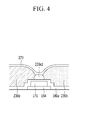
- FIG. 4 is a cross-sectional view illustrating a boundary between two adjacent pixels and its vicinity in a display device according to an exemplary embodiment.
- the display device may be, e.g., a liquid crystal display, and may include at least one display panel 100 and 200 and a liquid crystal layer 3.
- the present exemplary embodiment is mainly described with respect to a liquid crystal display that includes a lower panel 100 and an upper panel 200 disposed to face each other, and a liquid crystal layer 3 interposed therebetween, but a structure of exemplary embodiments of the display device is not limited thereto.
- the liquid crystal display may include one display panel and a liquid crystal layer.
- the upper panel 200 includes a substrate 210 made of glass or plastic, and an alignment layer 21 may be coated on the substrate 210.
- the alignment layer 21 may be a horizontal alignment layer.
- the alignment layer 21 may be rubbed in a direction.
- the alignment layer 21 may be photo-aligned by including a photo-reactive material.
- a gate conductor including gate lines 121 is disposed on a substrate 110 made of, e.g., transparent glass or plastic.
- the gate lines 121 may each include a gate electrode 124 and an end portion 129.
- the gate conductor may be made of an aluminum-based metal such as aluminum (Al) or an aluminum alloy, a silver-based metal such as silver (Ag) or a silver alloy, a copper-based metal such as copper (Cu) or a copper alloy, a molybdenum-based metal such as molybdenum (Mo) or a molybdenum alloy, chromium (Cr), tantalum (Ta), and titanium (Ti).
- the gate conductor may have a multilayered structure including at least two conductive layers having different physical properties.
- a gate insulating layer 140 made of a silicon nitride (SiNx), a silicon oxide (SiOx), or the like is formed on the gate conductor.
- the gate insulating layer 140 may have a multilayered structure including at least two insulating layers having different physical properties.
- a semiconductor 154 is disposed on the gate insulating layer 140.
- the semiconductor 154 may include amorphous silicon, polysilicon, or an oxide semiconductor.
- Ohmic contacts 163 and 165 may be further disposed on the semiconductor 154.
- the ohmic contacts 163 and 165 may be made of a material such as n+ hydrogenated amorphous silicon in which an n-type impurity such as phosphorus is doped at a high concentration, or of a silicide.
- the ohmic contacts 163 and 165 may form a pair to be disposed on the semiconductor 154. In the case where the semiconductor 154 is the oxide semiconductor, the ohmic contacts 163 and 165 may be omitted.
- the data line 171 transfers a data signal and mainly extends in a vertical direction to cross the gate line 121.
- the data line 171 may be periodically curved in order to improve transmittance.
- each data line 171 may be curved at a portion corresponding to a horizontal central line (not shown) of one pixel PX.
- an angle between most of the data lines 171 and the vertical direction may be approximately 5 to 7 degrees, but is not limited thereto.
- the data line 171 may be further curved at least once around the horizontal center line, and in this case, an angle between the data line 171 around the horizontal center line and the vertical direction may be approximately 5 to 7 degrees, but is not limited thereto.
- the data line 171 includes the source electrode 173. According to the exemplary embodiment illustrated in FIG. 1 , the source electrode 173 is not protruded from the data line 171, and may be disposed on the same line as the data line 171.
- the drain electrode 175 faces the source electrode 173.
- the drain electrode 175 may include a rod-shaped portion extending substantially parallel with the source electrode 173 and an extension which is opposite thereto.
- the data conductor may be made of refractory metal such as molybdenum, chromium, tantalum, and titanium, or an alloy thereof, and may have a multilayered structure including a refractory metal layer (not illustrated) and a low resistive conductive layer (not illustrated).
- An example of the multilayered structure may include a double layer including a chromium or molybdenum (alloy) lower layer and an aluminum (alloy) upper layer, and a triple layer including a molybdenum (alloy) lower layer, an aluminum (alloy) intermediate layer, and a molybdenum (alloy) upper layer.
- the data line 171 and the drain electrode 175 may be made of various metals or conductors in addition to the metals.
- the gate electrode 124, the source electrode 173, and the drain electrode 175 constitute one thin film transistor (TFT) together with the semiconductor 154, and a channel of the thin film transistor is positioned in the semiconductor 154 between the source electrode 173 and the drain electrode 175.
- TFT thin film transistor
- a first insulating layer 180a is disposed on the data conductor, the gate insulating layer 140, and an exposed portion of the semiconductor 154.
- the first insulating layer 180a may be made of, e.g., an inorganic insulating material.
- a plurality of color filters 230a and 230b may be disposed on the first insulating layer 180a.
- the color filters 230a and 230b may uniquely display one of the primary colors, and examples of the primary colors may include three primary colors of red, green, and blue, and three primary colors of yellow, cyan, and magenta, or four primary colors.
- the color filters 230a and 230b may further include a color filter displaying a mixed color of the primary colors or white in addition to the primary colors.
- Each of the color filters 230a and 230b may be longitudinally formed along a pixel column or a pixel row.
- the color filters 230a and 230b may include an organic material. In this case, the dielectric constant of the color filters 230a and 230b may have a low dielectric constant of less than about 4.
- the first color filter 230a and the second color filter 230b are respectively disposed at opposite sides of the data line 171 that generally extends in the vertical direction. Adjacent edges of the first and second color filters 230a and 230b are positioned to overlap the data line 171 thereabove. Accordingly, each of the first and second color filters 230a and 230b can be disposed to entirely cover the vicinity of the adjacent data line 171 in the horizontal direction.
- the first color filter 230a and the second color filter 230b may be disposed above the data line 171 to partially overlap each other as shown in FIG. 3 , or to not overlap each other as shown in FIG. 4 . Whether or not the first and second color filters 230a and 230b overlap each other above the data line 171 depends on alignment errors according to scattering of the manufacturing process of the display device.
- a dummy color filter 230cd is disposed above one data line and below a common electrode 270.
- the dummy color filter 230cd may be disposed below or above the first and second color filters 230a and 230b which are disposed to overlap each other or to be adjacent to each other above the data line 171.
- the dummy color filter 230cd displays a color different from those of the first and second color filters 230a and 230b.
- the pixels that do not include the first and second color filters 230a and 230b may include a third color filter (not shown) that displays the same color as that of the dummy color filter 230cd.
- the third color filter can be disposed to entirely cover the vicinity of the adjacent data line 171 in the horizontal direction.
- a thickness of the dummy color filter 230cd may be smaller than that of each of the first and second color filters 230a and 230b. Specifically, the thickness of the dummy color filter 230cd may be smaller than about half of the thickness of each of the first and second color filters 230a and 230b.
- the dummy color filter 230cd may also include an organic material. In this case, the dielectric constant of the dummy color filter 230cd may have a low dielectric constant of less than about 4.
- Opposite edges of the dummy color filter 230cd may be disposed within an area of the data line 171 which is disposed therebelow. Specifically, the opposite edges of dummy color filter 230cd may be disposed between opposite edges of the data line 171 which is disposed therebelow.
- a second insulating layer 180b is disposed on the first and second color filters 230a and 230b and the dummy color filter 230cd.
- the second insulating layer 180b may include an inorganic insulating material.
- the second insulating layer 180b may serve as an overcoat of the color filters 230a and 230b, to prevent the first and second color filters 230a and 230b from being exposed and provide a flat surface.
- the second insulating layer 180b may also serve to prevent impurities such as pigments of the first and second color filters 230a and 230b from flowing into the liquid crystal layer 3.
- the common electrode 270 may be disposed on the second insulating layer 180b.
- the common electrode 270 may have a planar shape, and may be formed as a plate on the entire substrate 110.
- the common electrodes 270 disposed at adjacent pixels PX are connected to each other to transfer a common voltage Vcom having a predetermined magnitude.
- the common electrode 270 may be made of a transparent conductive material such as ITO or IZO.
- the common electrode 270 may have an opening 273 formed in a region corresponding to a portion of the drain electrode 175.
- a third insulating layer 180c may be disposed on the common electrode 270.
- the third insulating layer 180c may be made of an inorganic insulating material.
- the first insulating layer 180a, the second insulating layer 180b, and the third insulating layer 180c include a contact hole 185a for exposing the drain electrode 175 and a contact hole 187 for exposing the end portion 179 of the data line 171.
- the contact hole 185a may be disposed in the opening 273 of the common electrode 270. In other words, the opening 273 of the common electrode 270 may surround the contact hole 185a.
- the first insulating layer 180a, second insulating layer 180b, third insulating layer 180c, and gate insulating layer 140 may include a contact hole 182 for exposing the end portion 129 of the gate line 121.
- a pixel electrode 191 and contact assistants 82 and 87 may be disposed on the third insulating layer 180c.
- the pixel electrode 191 may include a plurality of branch electrodes 192 that are disposed to overlap the common electrode 270. A slit 92 where the electrodes are removed is formed between adjacent branch electrodes 192.
- the branch electrodes 192 of the pixel electrode 191 may be disposed to extend substantially parallel with the data line 171.
- the pixel electrode 191 may be physically and electrically connected to the drain electrode 175 through the contact hole 185a to receive a voltage from the drain electrode 175.
- the contact assistant 82 is connected to the end portion 129 of the gate line 121 through the contact hole 182.
- the contact assistant 87 is connected to the end portion 179 of the data line 171 through the contact hole 187.
- the pixel electrode 191 and the contact assistants 82 and 87 may be made of a transparent conductive material such as ITO or IZO.
- stacking positions of the pixel electrode 191 and the common electrode 270 may be exchanged.
- the pixel electrode 191 may be disposed on the second insulating layer 180b, the third insulating layer 180c may be disposed thereon, and the common electrode 270 may be disposed thereon.
- no contact hole 185a may be formed in the third insulating layer 180c, and the common electrode 270 may not have the opening 273.
- the pixel electrode 191 may have a planer shape which fills most of the area of the pixel PX, and the common electrode 270 may include a plurality of branch electrodes (not illustrated) that are disposed to overlap the pixel electrode 191.
- An alignment layer 11 may be coated on the pixel electrode 191.
- the alignment layer 11 may be a horizontal alignment layer.
- the alignment layer 11 may be rubbed in a predetermined direction.
- the alignment layer 11 may be photo-aligned by including a photo-reactive material.
- a light blocking member 220 may be disposed on the pixel electrode 191.
- the light blocking member 220 may be referred to as a black matrix and may prevent light leakage between the pixels PX.
- the light blocking member 220 may include a pigment such as carbon black and a photosensitive organic material.
- the light blocking member 220 is disposed on the alignment layer 11, but the present invention is not limited thereto.
- the alignment layer 11 may be coated on the light blocking member 220 and the pixel electrode 191.
- the light blocking member 220 may include a spacer 221 and a main light blocker 222.
- the spacer 221 may serve to maintain a separated distance between the lower panel 100 and the upper panel 200.
- the main light blocker 222 has a thickness that is smaller than that of the spacer 221.
- the main light blocker 222 may include a first light blocker 222a disposed to cover the gate line 121 and to extend substantially parallel with the gate line 121, and a second light blocker 222b disposed to cover the data line 171 and to extend substantially parallel with the data line 171.
- the first light blocker 222a may include a first portion for covering the thin film transistor and a second portion for covering the contact hole 185a for exposing the drain electrode 175.
- the second light blocker 222b may be omitted.
- the liquid crystal layer 3 includes liquid crystal molecules (not illustrated) having dielectric anisotropy.
- the liquid crystal molecules may be aligned such that long axes thereof are parallel with the display panels 100 and 200 in a state in which no electric field is generated in the liquid crystal layer 3.
- the liquid crystal molecules may have positive dielectric anisotropy.
- the liquid crystal molecules may be nematic liquid crystal molecules having a structure in which the long-axial directions thereof are spirally twisted from the lower panel 100 to the upper panel 200.
- the liquid crystal molecules may be aligned such that long axes thereof are perpendicular to the display panels 100 and 200 in a state in which no electric field is generated in the liquid crystal layer 3.
- the liquid crystal molecules may have negative dielectric anisotropy.
- the disposition and structure of the pixel electrode 191 and the common electrode 270 may be modified, unlike those illustrated in FIG. 1 and FIG. 2 .
- the pixel electrode 191 may receive a data voltage through the thin film transistor, and the common electrode 270 may receive a common voltage Vcom. Then, the liquid crystal molecules of the liquid crystal layer 3 disposed between the pixel electrode 191 and the common electrode 270 are rearranged by an electric field generated in the liquid crystal layer 3 by the pixel electrode 191 and the common electrode 270 as the field generating electrodes. The polarization of light passing through the liquid crystal layer 3 is adjusted by the rearranged liquid crystal molecules, thereby accomplishing images having a desired luminance.
- branch electrodes 192 of the pixel electrode 191 can generate a fringe field in the liquid crystal layer 3 together with the common electrode 270, to determine alignment directions of the liquid crystal molecules. Accordingly, as in the exemplary embodiment, when the branch electrodes 192 included in one pixel electrode 191 have different directional slopes, directions in which the liquid crystal molecules are inclined are varied, thereby improving a standard viewing angle.
- the light blocking member 220, the color filters 230a and 230b, the pixel electrode 191, and the thin film transistor can be easily aligned by disposing the first and second color filters 230a and 230b and the light blocking member 220 in the lower panel 100 together with the thin film transistor, thereby reducing alignment errors caused by scattering in the process.
- the overlapped portions of the first and second color filters 230a and 203b are positioned between the data line 171 and the common electrode 270, thereby reducing parasitic capacitance between the data line 171 and the common electrode 270. This can prevent fluctuation of the common voltage Vcom of the common electrode 270 caused by coupling with data signals transferred through the data line 171.
- an alignment error generated by scattering in the process causes the first and second color filters 230a and 230b, which overlap each other above the data line 171, to be separated from each other, or causes the overlapped portions of the first and second color filters 230a and 230b to be reduced, thereby increasing the parasitic capacitance between the data line 171 and the common electrode 270.
- the first and second color filters 230a and 230b overlap each other above the dummy color filter 230cd, which is disposed below the common electrode 270 and above the data line 171.
- this can reduce the crosstalk between the data line 171 and the adjacent pixel electrode 191, thereby decreasing the light leakage generated by distortion of the electric field. As a result, the width of the data line 171 in which the dummy color filter 230cd is disposed can be further reduced.
- an organic film including an organic material between the data line 171 and the common electrode 270 unlike the conventional art, thereby reducing a cost of the material of the organic film.
- there is no probability of reducing transmittance caused by the organic film and it is possible to prevent the contamination of the liquid crystal layer 3 caused by the organic material of the organic film.
- FIG. 5 is a schematic cross-sectional view illustrating four adjacent pixels in a display device according to an exemplary embodiment.
- FIG. 6 is a cross-sectional view illustrating a boundary between two adjacent pixels and its vicinity in a display device according to an exemplary embodiment.
- the display device includes a plurality of data lines 171, a plurality of color filters 230a, 230b, and 230c disposed above the data line 171, and a dummy color filter 230cd.
- the first color filter 230a, the second color filter 230b, and the third color filter 230c may display different colors, e.g., red, green, and blue, respectively. However, the colors may be exchanged or different colors may be displayed without being limited thereto.
- the specific kinds of color filters are exemplary, and not meant to serve as limitations. This is true of a display device including four or more kinds of color filters.
- the dummy color filter 230cd may be disposed above the data line 171, between the adjacent first and second color filters 230a and 230b and the data line 171, or on the first and second color filters 230a and 230b. In the present exemplary embodiment, it is illustrated that the dummy color filter 230cd is disposed between the first and second color filters 230a and 230b and above the data line 171.
- the dummy color filter 230cd may include a pigment that displays substantially the same color as that of the third color filter 230c.
- No dummy color filter may be formed on the data lines 171 between the second and third color filters 230b and 230c and/or between third and first color filter 230c and 230a.
- a second width W2 of the data line 171 positioned between the second and third color filters 230b and 230c and/or a third width W3 of the data line 171 positioned between the third and first color filters 230c and 230a may be larger than a first width W1 of the data line 171 which is disposed to overlap the dummy color filter 230cd.
- both the first color filter 230a and the second color filter 230b are required to overlap the data line 171 above a portion of the data line 171 above which no dummy color filter is disposed. Accordingly, it is necessary to provide a minimum margin of partial widths W11 and W13. Further, the first and second color filters 230a and 230b are required to overlap each other above the data line 171 to reduce parasitic capacitance between the data line 171 and the common electrode 270, and thus it is necessary to provide a minimum margin of a partial width W12 for the overlapping of the first and second color filters 230a and 230b.
- the widths W2 and W3 of the data line 171 above which no dummy color filter is disposed may be larger than the width W1 of the data line 171 above which the dummy color filter 230cd is disposed.
- the widths W2 and width W3 are required to be widened to block light leakage between the pixels PX.
- the dummy color filter 230cd can reduce parasitic capacitance between the data line 171 and the common electrode 270 or the pixel electrode 191 of the adjacent pixels PX, and thus a margin for the partial width W12 illustrated in FIG. 6 can be omitted. Accordingly, it is possible to further reduce the width W1 of the data line 171. Further, since the parasitic capacitance between the data line 171 and the adjacent pixels PX can be reduced by the action of the dummy color filter 230cd, the width W1 of the data line 171 can be reduced by as much as the parasitic capacitance is reduced. Accordingly, it is possible to improve the aperture ratio and transmittance of the pixels PX and to easily design the display device with high resolution.
- FIG. 7 is a schematic cross-sectional view illustrating four adjacent pixels of an intermediate product of a display device in a step in a process of a manufacturing method of the display device according to an exemplary embodiment
- FIG. 8 is a schematic cross-sectional view illustrating four adjacent pixels of an intermediate product of a display device in a step next to the step illustrated FIG. 7 in the process of the manufacturing method of the display device according to the exemplary embodiment
- FIG. 9 is a schematic cross-sectional view illustrating four adjacent pixels of an intermediate product of a display device in a step next to the step illustrated FIG. 8 in the process of the manufacturing method of the display device according to the exemplary embodiment.
- the gate conductor including the gate line 121, the gate insulating layer 140, and the semiconductor 154 are formed on the substrate 110, and then a conductive material such as a metal is stacked thereon and patterned to form the data conductor including the data lines 171 and the drain electrodes 175.
- a conductive material such as a metal is stacked thereon and patterned to form the data conductor including the data lines 171 and the drain electrodes 175.
- widths between two adjacent data lines 171 may be substantially the same, or a first width between a first pair of adjacent data lines 171 may be smaller than a second width between a second pair of adjacent data lines 171 that are adjacent thereto.
- a third color filter material is coated on the data lines 171 and is patterned by using, e.g., a photolithography process to form a plurality of third color filters 230c and dummy color filters 230cd.
- the dummy color filters 230cd may be disposed above the data lines 171 of which the widths are relatively small.
- the third color filter 230c may be formed at a pixel PX disposed between two data lines 171.
- the third color filters 230c and the dummy color filters 230cd are separated from each other, and are disposed on different data lines 171.
- the thickness of the dummy color filters 230cd is formed to be smaller than that of the third color filters 230c, and a photomask used for the photolithography process may include transparent regions positioned to correspond to areas at which the third color filters 230c are to be formed, and halftone regions or slits positioned to correspond to areas at which the dummy color filters 230cd are to be formed.
- the photomask may include opaque regions for areas at which the third color filter material needs to be removed. In this case, a portion of the third color filter material remaining after light irradiation may have negative photosensitivity. In contrast, when the third color filter material has positive photosensitivity, the transparency of the aforementioned photomask may be reversed.
- a first color filter material for displaying a color different from that of the third color filters 230c is coated and is patterned by using, e.g., the photolithography process to form a plurality of first color filters 230a disposed at pixels PX, each of which is disposed between the adjacent data lines 171. Edges of the first color filters 230a may be formed to at least partially overlap the dummy color filters 230cd.
- a second color filter material for displaying a color different from those of the first and third color filters 230a and 230c is coated and is patterned by using, e.g., the photolithography process to form a plurality of second color filters 230b disposed at pixels PX each of which is disposed between the adjacent data lines 171. Edges of the second color filters 230b may be formed to at least partially overlap the dummy color filters 230cd, or to not overlap the dummy color filters 230cd.
- FIG. 10 a display device according to an exemplary embodiment will be described with reference to FIG. 10 in addition to FIG. 1 to FIG. 5 which are described above.
- FIG. 10 is a schematic cross-sectional view illustrating four adjacent pixels in a display device according to an exemplary embodiment.
- the display device of the present exemplary embodiment is mostly the same as the display device described with reference to FIG. 5 , but may further include a dummy color filter 230ad.
- the dummy color filter 230ad may be disposed above the data line 171 above which no dummy color filter 230cd is disposed, for example, above the data line 171 between the second color filter 230b and the third color filter 230c, and below the common electrode 270.
- the dummy color filter 230ad may be disposed above the third color filter 230c and below the second color filter 230b.
- the dummy color filter 230ad may include a region that is disposed between the second and third color filters 230b and 230c.
- the dummy color filter 230ad displays a color different from those of the second and third color filters 230b and 230c.
- the dummy color filter 230ad may display the same color as that of the first color filter 230a.
- the thickness of the dummy color filter 230ad may be smaller than that of each of the first to third color filters 230a, 230b, and 230c.
- the thickness of the dummy color filter 230ad may be smaller than about half of the thickness of each of the first to third color filters 230a, 230b, and 230c.
- the dummy color filter 230ad may also include an organic material. In this case, the dielectric constant of the dummy color filter 230ad may have a low dielectric constant of less than about 4.
- Opposite edges of the dummy color filter 230ad may be disposed within an area of the data line 171 which is disposed therebelow. Specifically, the opposite edges of dummy color filter 230ad may be disposed between opposite edges of the data line 171 which is disposed therebelow.
- an alignment error generated by scattering in the process causes the second and third color filters 230b and 230c, which are overlapped with each other above the data line 171, to be separated from each other, or causes the overlapped portions of the second and third color filter 230b and 230c to be reduced, thereby increasing the parasitic capacitance between the data line 171 and the common electrode 270.
- the second and third color filters 230b and 230c are overlapped with each other above the dummy color filter 230ad, which is disposed below the common electrode 270 and above the data line 171.
- this can reduce the crosstalk between the data line 171 and the adjacent pixel electrode 191, thereby decreasing the light leakage generated by distortion of the electric field. As a result, the width of the data line 171 in which the dummy color filter 230ad is disposed can be further reduced.
- the width W3 of the data line 171 above which no dummy color filter 230cd or 230ad is formed may be larger than the width W1 or W2 of the data line 171 which is disposed to overlap the dummy color filter 230cd or 230ad.
- the first and third color filters 230a and 230c are required to overlap each other above the data line 171 to reduce parasitic capacitance between the data line 171 and the common electrode 270, and thus it is necessary to provide a minimum margin area for the overlapping of the first and third color filters 230a and 230c. Accordingly, width W3 of the data line 171 above which no dummy color filter 230cd or 230ad is formed may be larger than the width W1 or W2 of the data line 171 above which the dummy color filter 230cd or 230ad is disposed.
- the dummy color filter 230ad can reduce parasitic capacitance between the data line 171 and the common electrode 270 or the pixel electrode 191 of the adjacent pixels PX, and thus it is possible to further reduce the width W2 of the data line 171. Further, since the parasitic capacitance between the data line 171 and the adjacent pixels PX can be reduced by the action of the dummy color filter 230ad, the width W2 of the data line 171 can be reduced by as much as the parasitic capacitance is reduced. Accordingly, it is possible to improve the aperture ratio and transmittance of the pixels PX and to easily design the display device of high resolution.
- the dummy color filter 230cd of illustrated in FIG. 10 may be omitted.
- FIG. 11 is a schematic cross-sectional view illustrating four adjacent pixels of an intermediate product of a display device in a step in a process of a manufacturing method of the display device according to an exemplary embodiment
- FIG. 12 is a schematic cross-sectional view illustrating four adjacent pixels of an intermediate product of a display device in a step next to the step illustrated FIG. 11 in the process of the manufacturing method of the display device according to the exemplary embodiment
- FIG. 13 is a schematic cross-sectional view illustrating four adjacent pixels of an intermediate product of a display device in a step next to the step illustrated FIG. 12 in the process of the manufacturing method of the display device according to the exemplary embodiment.
- a manufacturing method of the display device according to an exemplary embodiment is mostly the same as the manufacturing method of the display device according to the exemplary embodiment illustrated in FIG. 7 to FIG. 9 which are described above, and thus it will be described based on the differences therebetween.
- a conductive material such as a metal is stacked on the substrate 110 and patterned to form the data conductor including the data lines 171 and the drain electrodes 175.
- Widths between two adjacent data lines 171 may be substantially the same, or a first width between a first pair of adjacent data lines 171 may be larger than a second width between a second pair of adjacent data lines 171 that are adjacent thereto.
- a third color filter material is coated on the data lines 171 and is patterned by using, e.g., a photolithography process to form a plurality of third color filters 230c and dummy color filters 230cd.
- the dummy color filters 230cd may be disposed above the data lines 171 of which the widths are relatively small.
- the third color filter 230c may be formed at a pixel PX disposed between two data lines 171.
- the third color filters 230c and the dummy color filters 230cd are separated from each other, and are disposed on different data lines 171.
- the thickness of the dummy color filters 230cd is formed to be smaller than that of the third color filters 230c, and a photomask used for the photolithography process may include transparent regions positioned to correspond to areas at which the third color filters 230c are to be formed, and halftone regions or slits positioned to correspond to areas at which the dummy color filters 230cd are to be formed.
- the photomask may include opaque regions for areas at which the third color filter material needs to be removed.
- a first color filter material for displaying a color different from that of the third color filters 230c is coated and is patterned by using, e.g., the photolithography process to form a plurality of first color filters 230a and dummy color filters 230ad disposed at pixels PX each of which is disposed between the adjacent data lines 171. Edges of the first color filters 230a may be formed to at least partially overlap the dummy color filters 230cd. The dummy color filters 230ad may be formed to overlap the edges of the third color filters 230c, or may be formed to not overlap the edges of the third color filters 230c.
- the thickness of the dummy color filter 230ad is formed to be smaller than that of the first color filter 230a, and a photomask used for the photolithography process may include transparent regions positioned to correspond to areas at which the first color filter 230a are to be formed, and halftone regions or slits positioned to correspond to areas at which the dummy color filter 230ad are to be formed.
- the photomask may include opaque regions for areas at which the first color filter material needs to be removed.
- a second color filter material for displaying a color different from those of the first and third color filters 230a and 230c is coated and is patterned by using, e.g., the photolithography process to form a plurality of second color filters 230b disposed at pixels PX each of which is disposed between the adjacent data lines 171.
- One edge of the second color filter 230b may be formed to at least partially overlap the dummy color filters 230cd, and another edge thereof may be formed to at least partially overlap the dummy color filters 230ad, or to not overlap the dummy color filters 230ad.
- FIG. 14 a display device according to an exemplary embodiment of the present invention will be described with reference to FIG. 14 in addition to FIG. 1 to FIG. 5 which are described above.
- FIG. 14 is a schematic cross-sectional view illustrating four adjacent pixels in a display device according to an exemplary embodiment of the present invention.
- the display device of the present exemplary embodiment is mostly the same as the display device described with reference to FIG. 10 , but may further include a dummy color filter 230bd.
- the dummy color filter 230bd may be disposed above the data line 171 above which the dummy color filters 230cd and 230ad are not disposed, for example, above the data line 171 between the third color filter 230c and the first color filter 230a, and below the common electrode 270.
- the dummy color filter 230bd may be disposed above the third color filter 230c and below the second color filter 230b.
- the dummy color filter 230bd may include a region that is disposed between the third and first color filters 230c and 230a.
- the dummy color filter 230bd displays a color different from those of the third and first color filters 230c and 230a.
- the dummy color filter 230bd may display the same color as that of the second color filter 230b.
- the thickness of the dummy color filter 230bd may be smaller than that of each of the first to third color filters 230a, 230b, and 230c.
- the thickness of the dummy color filter 230bd may be smaller than about half of the thickness of each of the first to third color filters 230a, 230b, and 230c.
- the dummy color filter 230bd may also include an organic material. In this case, the dielectric constant of the dummy color filter 230bd may have a low dielectric constant of less than about 4.
- Opposite edges of the dummy color filter 230bd may be disposed within an area of the data line 171 which is disposed therebelow. Specifically, the opposite edges of the dummy color filter 230bd may be disposed between opposite edges of the data line 171 which is disposed therebelow.
- an alignment error generated by scattering in the process causes the third and first color filters 230c and 230a which are overlapped with each other above the data line 171 to be separated from each other, or causes the overlapped portions of the third and first color filters 230c and 230a to be reduced, thereby increasing the parasitic capacitance between the data line 171 and the common electrode 270.
- the dummy color filter 230bd is disposed below the common electrode 270 and above the data line 171 above which the third and first color filters 230c and 230a are overlapped with each other.
- this can reduce the crosstalk between the data line 171 and the adjacent pixel electrode 191, thereby decreasing the light leakage generated by distortion of the electric field. As a result, the width of the data line 171 in which the dummy color filter 230bd is disposed can be further reduced.
- the dummy color filters 230cd, 230ad, and 230bd are disposed above all the data lines 171, all the widths W1, W2, and W3 of the data lines 171 can be reduced.
- the dummy color filters 230cd, 230ad, and 230bd are disposed between the data lines 171 and the common electrode 270, and thus margins for reducing the widths W1, W2, and W3 of the data lines 171 can be accomplished even though the adjacent color filters 230a, 230b, and 230c do not overlap each other above the data lines 171.
- the parasitic capacitance between the data lines 171 and the adjacent pixels PX can be reduced by the action of the dummy color filters 230ad, 230ad, and 230bd, the widths W1, W2, and W3 of the data lines 171 can be reduced by as much as the parasitic capacitance is reduced. Accordingly, it is possible to improve the aperture ratio and transmittance of the pixels PX and to easily design the display device with high resolution.
- All the widths W1, W2, and W3 of the data lines 171 may be substantially the same.
- a manufacturing method of the display device according to the exemplary embodiment illustrated in FIG. 14 is mostly the same as the manufacturing method of the display device according to the exemplary embodiment illustrated in FIG. 11 to FIG. 13 which are described above, but the dummy color filter 230bd is formed above the data line 171 between the third color filter 230c and the first color filter 230a together with the second color filter 230b when the second color filter 230b is formed after the first and third color filters 230a and 230c are formed.
- the thickness of the dummy color filter 230bd is formed to be smaller than that of the second color filter 230b
- a photomask used for the photolithography process may include transparent regions positioned to correspond to areas at which the second color filters 230b are to be formed, and halftone regions or slits positioned to correspond to areas at which the dummy color filters 230bd are to be formed.
- the photomask may include opaque regions for areas at which the second color filter material needs to be removed.
- At least one of the dummy color filters 230cd and 230ad of the exemplary embodiment illustrated in FIG. 14 may be omitted.
- a display device and a manufacturing method thereof capable of preventing light leakage and display errors caused by parasitic capacitance between field generating electrodes and data lines without using an organic film, and accomplishing a low manufacturing cost of the display device and a simplified manufacturing process.
- ordinal numbers such as first, second, third, etc. have been placed before the color filters and dummy color filters in each of the specification and claims in order to distinguish between different color filter or distinguish between different dummy color filters.
- ordinal numbers placed before a color filter or dummy color filter may be different in the claims and in the specification or drawings even when they indicate the same color filter or dummy color filter, and any color filter or dummy color filter having a same ordinal number in different claims may indicate different color filter or dummy color filter, and any color filter or dummy color filter having a same ordinal number in a claim and in the specification may indicate different color filter or dummy color filter.
Applications Claiming Priority (1)
| Application Number | Priority Date | Filing Date | Title |
|---|---|---|---|
| KR1020150006325A KR102294835B1 (ko) | 2015-01-13 | 2015-01-13 | 표시 장치 및 그 제조 방법 |
Publications (2)
| Publication Number | Publication Date |
|---|---|
| EP3045962A1 true EP3045962A1 (fr) | 2016-07-20 |
| EP3045962B1 EP3045962B1 (fr) | 2017-12-13 |
Family
ID=54329416
Family Applications (1)
| Application Number | Title | Priority Date | Filing Date |
|---|---|---|---|
| EP15189758.4A Active EP3045962B1 (fr) | 2015-01-13 | 2015-10-14 | Dispositif d'affichage et son procédé de fabrication |
Country Status (4)
| Country | Link |
|---|---|
| US (1) | US9696578B2 (fr) |
| EP (1) | EP3045962B1 (fr) |
| KR (1) | KR102294835B1 (fr) |
| CN (1) | CN105785674B (fr) |
Families Citing this family (9)
| Publication number | Priority date | Publication date | Assignee | Title |
|---|---|---|---|---|
| JP6656907B2 (ja) * | 2015-12-17 | 2020-03-04 | 株式会社ジャパンディスプレイ | 液晶表示装置 |
| US10254579B2 (en) * | 2016-07-29 | 2019-04-09 | Lg Display Co., Ltd. | Curved display device |
| KR102661122B1 (ko) * | 2016-11-21 | 2024-04-26 | 삼성디스플레이 주식회사 | 표시 장치 및 이의 제조 방법 |
| KR20180064613A (ko) * | 2016-12-05 | 2018-06-15 | 삼성디스플레이 주식회사 | 표시 장치 |
| CN107247375B (zh) * | 2017-06-20 | 2020-06-05 | 深圳市华星光电技术有限公司 | 一种通过光罩直接拼接形成的coa基板及显示面板 |
| CN109613741A (zh) * | 2019-01-11 | 2019-04-12 | 惠科股份有限公司 | 显示面板及其制造方法 |
| CN110716359A (zh) * | 2019-10-14 | 2020-01-21 | 深圳市华星光电技术有限公司 | 阵列基板及其制造方法与对准精度检测方法 |
| KR20210081162A (ko) * | 2019-12-23 | 2021-07-01 | 엘지디스플레이 주식회사 | 표시 장치 |
| US20210305324A1 (en) * | 2020-03-30 | 2021-09-30 | Canon Kabushiki Kaisha | Color filter array, electronic device, and method of manufacturing color filter array |
Citations (3)
| Publication number | Priority date | Publication date | Assignee | Title |
|---|---|---|---|---|
| US20050253984A1 (en) * | 2004-03-30 | 2005-11-17 | Lg.Philips Lcd Co., Ltd. | Liquid crystal display and method for manufacturing the same |
| US20060033878A1 (en) * | 2004-08-13 | 2006-02-16 | Fujitsu Display Technologies Corporation | Substrate for liquid crystal display device and liquid crystal display device having the same |
| US20100321283A1 (en) * | 2009-06-18 | 2010-12-23 | Hitachi Displays, Ltd. | Liquid crystal display device and manufacturing method for same |
Family Cites Families (15)
| Publication number | Priority date | Publication date | Assignee | Title |
|---|---|---|---|---|
| JP3536447B2 (ja) | 1995-06-26 | 2004-06-07 | カシオ計算機株式会社 | カラー液晶表示素子 |
| JP4215905B2 (ja) * | 1999-02-15 | 2009-01-28 | シャープ株式会社 | 液晶表示装置 |
| JP2003131020A (ja) | 2001-10-26 | 2003-05-08 | Toppan Printing Co Ltd | カラーフィルタの製造方法 |
| JP2004045726A (ja) | 2002-07-11 | 2004-02-12 | Citizen Watch Co Ltd | カラー液晶装置 |
| JP2006337590A (ja) | 2005-05-31 | 2006-12-14 | Optrex Corp | カラー液晶表示パネル |
| KR101327795B1 (ko) * | 2006-12-12 | 2013-11-11 | 삼성디스플레이 주식회사 | 액정표시장치 |
| KR20080093504A (ko) | 2007-04-17 | 2008-10-22 | 엘지디스플레이 주식회사 | 씨오에이구조 횡전계 방식 액정표시장치용 어레이기판과 그제조방법 |
| KR101472849B1 (ko) | 2008-05-09 | 2014-12-15 | 삼성디스플레이 주식회사 | 박막트랜지스터 기판, 이의 제조 방법 및 이를 갖는액정표시패널 |
| JP5507175B2 (ja) * | 2009-09-25 | 2014-05-28 | 株式会社ジャパンディスプレイ | 液晶表示装置およびその製造方法 |
| KR101595818B1 (ko) | 2009-08-26 | 2016-02-22 | 삼성디스플레이 주식회사 | 박막 트랜지스터 기판 및 그 제조 방법 |
| KR101620531B1 (ko) | 2009-10-08 | 2016-05-13 | 삼성디스플레이 주식회사 | 액정 표시 장치 |
| KR101101021B1 (ko) | 2009-10-09 | 2011-12-29 | 삼성모바일디스플레이주식회사 | 액정표시장치 및 그 제조방법 |
| TWI397757B (zh) * | 2009-12-22 | 2013-06-01 | Au Optronics Corp | 聚合物穩定配向液晶顯示面板及液晶顯示面板 |
| KR102204976B1 (ko) | 2013-11-13 | 2021-01-20 | 삼성디스플레이 주식회사 | 표시 장치 및 그것의 제조 방법 |
| KR102130545B1 (ko) | 2013-11-27 | 2020-07-07 | 삼성디스플레이 주식회사 | 액정 표시 장치 |
-
2015
- 2015-01-13 KR KR1020150006325A patent/KR102294835B1/ko active IP Right Grant
- 2015-06-17 US US14/741,900 patent/US9696578B2/en active Active
- 2015-09-11 CN CN201510580545.9A patent/CN105785674B/zh active Active
- 2015-10-14 EP EP15189758.4A patent/EP3045962B1/fr active Active
Patent Citations (3)
| Publication number | Priority date | Publication date | Assignee | Title |
|---|---|---|---|---|
| US20050253984A1 (en) * | 2004-03-30 | 2005-11-17 | Lg.Philips Lcd Co., Ltd. | Liquid crystal display and method for manufacturing the same |
| US20060033878A1 (en) * | 2004-08-13 | 2006-02-16 | Fujitsu Display Technologies Corporation | Substrate for liquid crystal display device and liquid crystal display device having the same |
| US20100321283A1 (en) * | 2009-06-18 | 2010-12-23 | Hitachi Displays, Ltd. | Liquid crystal display device and manufacturing method for same |
Also Published As
| Publication number | Publication date |
|---|---|
| CN105785674B (zh) | 2020-11-27 |
| US20160202544A1 (en) | 2016-07-14 |
| US9696578B2 (en) | 2017-07-04 |
| KR20160087474A (ko) | 2016-07-22 |
| CN105785674A (zh) | 2016-07-20 |
| KR102294835B1 (ko) | 2021-08-27 |
| EP3045962B1 (fr) | 2017-12-13 |
Similar Documents
| Publication | Publication Date | Title |
|---|---|---|
| EP3045962B1 (fr) | Dispositif d'affichage et son procédé de fabrication | |
| US20180267371A1 (en) | Liquid crystal display | |
| EP2790058B1 (fr) | Affichage à cristaux liquides de type à matrice active qui emploie une configuration horizontale du champ électrique et capacité parasite réduite d'un pixel | |
| KR102128969B1 (ko) | 액정 표시 장치 및 그 제조 방법 | |
| EP1655632A1 (fr) | Panneau à réseau de transistors à couche mince | |
| US20100060838A1 (en) | Liquid crystal display and method thereof | |
| US9618801B2 (en) | Display device having a furrow structure on a light blocking member | |
| US20150062521A1 (en) | Liquid crystal display | |
| CN117590639A (zh) | 显示面板 | |
| US8355090B2 (en) | Liquid crystal display having reduced kickback effect | |
| US20090122248A1 (en) | Thin film transistor substrate and liquid crystal display having the same | |
| US9851608B2 (en) | Liquid crystal display | |
| CN110967882A (zh) | 显示设备 | |
| US9075279B2 (en) | Display device | |
| US10775676B2 (en) | Display device | |
| US9977271B2 (en) | Liquid crystal display | |
| US20160062169A1 (en) | Liquid crystal display device | |
| US10788719B2 (en) | Liquid crystal display device | |
| US9891485B2 (en) | Liquid crystal display | |
| US9904111B2 (en) | Liquid crystal display | |
| US20160209718A1 (en) | Liquid crystal display | |
| US10330990B2 (en) | Liquid crystal display device | |
| US9679920B2 (en) | Liquid crystal display |
Legal Events
| Date | Code | Title | Description |
|---|---|---|---|
| PUAI | Public reference made under article 153(3) epc to a published international application that has entered the european phase |
Free format text: ORIGINAL CODE: 0009012 |
|
| AK | Designated contracting states |
Kind code of ref document: A1 Designated state(s): AL AT BE BG CH CY CZ DE DK EE ES FI FR GB GR HR HU IE IS IT LI LT LU LV MC MK MT NL NO PL PT RO RS SE SI SK SM TR |
|
| AX | Request for extension of the european patent |
Extension state: BA ME |
|
| 17P | Request for examination filed |
Effective date: 20161222 |
|
| RBV | Designated contracting states (corrected) |
Designated state(s): AL AT BE BG CH CY CZ DE DK EE ES FI FR GB GR HR HU IE IS IT LI LT LU LV MC MK MT NL NO PL PT RO RS SE SI SK SM TR |
|
| GRAP | Despatch of communication of intention to grant a patent |
Free format text: ORIGINAL CODE: EPIDOSNIGR1 |
|
| INTG | Intention to grant announced |
Effective date: 20170517 |
|
| RAP1 | Party data changed (applicant data changed or rights of an application transferred) |
Owner name: SAMSUNG DISPLAY CO., LTD. |
|
| RIN1 | Information on inventor provided before grant (corrected) |
Inventor name: LEE, JEONG HO Inventor name: RO, SUNG IN |
|
| GRAJ | Information related to disapproval of communication of intention to grant by the applicant or resumption of examination proceedings by the epo deleted |
Free format text: ORIGINAL CODE: EPIDOSDIGR1 |
|
| GRAR | Information related to intention to grant a patent recorded |
Free format text: ORIGINAL CODE: EPIDOSNIGR71 |
|
| GRAS | Grant fee paid |
Free format text: ORIGINAL CODE: EPIDOSNIGR3 |
|
| INTC | Intention to grant announced (deleted) | ||
| GRAA | (expected) grant |
Free format text: ORIGINAL CODE: 0009210 |
|
| INTG | Intention to grant announced |
Effective date: 20171011 |
|
| REG | Reference to a national code |
Ref country code: GB Ref legal event code: FG4D |
|
| REG | Reference to a national code |
Ref country code: AT Ref legal event code: REF Ref document number: 954950 Country of ref document: AT Kind code of ref document: T Effective date: 20171215 Ref country code: CH Ref legal event code: EP |
|
| REG | Reference to a national code |
Ref country code: IE Ref legal event code: FG4D |
|
| REG | Reference to a national code |
Ref country code: DE Ref legal event code: R096 Ref document number: 602015006616 Country of ref document: DE |
|
| REG | Reference to a national code |
Ref country code: NL Ref legal event code: MP Effective date: 20171213 |
|
| PG25 | Lapsed in a contracting state [announced via postgrant information from national office to epo] |
Ref country code: FI Free format text: LAPSE BECAUSE OF FAILURE TO SUBMIT A TRANSLATION OF THE DESCRIPTION OR TO PAY THE FEE WITHIN THE PRESCRIBED TIME-LIMIT Effective date: 20171213 Ref country code: SE Free format text: LAPSE BECAUSE OF FAILURE TO SUBMIT A TRANSLATION OF THE DESCRIPTION OR TO PAY THE FEE WITHIN THE PRESCRIBED TIME-LIMIT Effective date: 20171213 Ref country code: NO Free format text: LAPSE BECAUSE OF FAILURE TO SUBMIT A TRANSLATION OF THE DESCRIPTION OR TO PAY THE FEE WITHIN THE PRESCRIBED TIME-LIMIT Effective date: 20180313 |
|
| REG | Reference to a national code |
Ref country code: AT Ref legal event code: MK05 Ref document number: 954950 Country of ref document: AT Kind code of ref document: T Effective date: 20171213 |
|
| PG25 | Lapsed in a contracting state [announced via postgrant information from national office to epo] |
Ref country code: LV Free format text: LAPSE BECAUSE OF FAILURE TO SUBMIT A TRANSLATION OF THE DESCRIPTION OR TO PAY THE FEE WITHIN THE PRESCRIBED TIME-LIMIT Effective date: 20171213 Ref country code: RS Free format text: LAPSE BECAUSE OF FAILURE TO SUBMIT A TRANSLATION OF THE DESCRIPTION OR TO PAY THE FEE WITHIN THE PRESCRIBED TIME-LIMIT Effective date: 20171213 Ref country code: HR Free format text: LAPSE BECAUSE OF FAILURE TO SUBMIT A TRANSLATION OF THE DESCRIPTION OR TO PAY THE FEE WITHIN THE PRESCRIBED TIME-LIMIT Effective date: 20171213 Ref country code: GR Free format text: LAPSE BECAUSE OF FAILURE TO SUBMIT A TRANSLATION OF THE DESCRIPTION OR TO PAY THE FEE WITHIN THE PRESCRIBED TIME-LIMIT Effective date: 20180314 Ref country code: BG Free format text: LAPSE BECAUSE OF FAILURE TO SUBMIT A TRANSLATION OF THE DESCRIPTION OR TO PAY THE FEE WITHIN THE PRESCRIBED TIME-LIMIT Effective date: 20180313 |
|
| PG25 | Lapsed in a contracting state [announced via postgrant information from national office to epo] |
Ref country code: NL Free format text: LAPSE BECAUSE OF FAILURE TO SUBMIT A TRANSLATION OF THE DESCRIPTION OR TO PAY THE FEE WITHIN THE PRESCRIBED TIME-LIMIT Effective date: 20171213 |
|
| PG25 | Lapsed in a contracting state [announced via postgrant information from national office to epo] |
Ref country code: SK Free format text: LAPSE BECAUSE OF FAILURE TO SUBMIT A TRANSLATION OF THE DESCRIPTION OR TO PAY THE FEE WITHIN THE PRESCRIBED TIME-LIMIT Effective date: 20171213 Ref country code: CY Free format text: LAPSE BECAUSE OF FAILURE TO SUBMIT A TRANSLATION OF THE DESCRIPTION OR TO PAY THE FEE WITHIN THE PRESCRIBED TIME-LIMIT Effective date: 20171213 Ref country code: EE Free format text: LAPSE BECAUSE OF FAILURE TO SUBMIT A TRANSLATION OF THE DESCRIPTION OR TO PAY THE FEE WITHIN THE PRESCRIBED TIME-LIMIT Effective date: 20171213 Ref country code: CZ Free format text: LAPSE BECAUSE OF FAILURE TO SUBMIT A TRANSLATION OF THE DESCRIPTION OR TO PAY THE FEE WITHIN THE PRESCRIBED TIME-LIMIT Effective date: 20171213 Ref country code: ES Free format text: LAPSE BECAUSE OF FAILURE TO SUBMIT A TRANSLATION OF THE DESCRIPTION OR TO PAY THE FEE WITHIN THE PRESCRIBED TIME-LIMIT Effective date: 20171213 |
|
| PG25 | Lapsed in a contracting state [announced via postgrant information from national office to epo] |
Ref country code: SM Free format text: LAPSE BECAUSE OF FAILURE TO SUBMIT A TRANSLATION OF THE DESCRIPTION OR TO PAY THE FEE WITHIN THE PRESCRIBED TIME-LIMIT Effective date: 20171213 Ref country code: PL Free format text: LAPSE BECAUSE OF FAILURE TO SUBMIT A TRANSLATION OF THE DESCRIPTION OR TO PAY THE FEE WITHIN THE PRESCRIBED TIME-LIMIT Effective date: 20171213 Ref country code: AT Free format text: LAPSE BECAUSE OF FAILURE TO SUBMIT A TRANSLATION OF THE DESCRIPTION OR TO PAY THE FEE WITHIN THE PRESCRIBED TIME-LIMIT Effective date: 20171213 Ref country code: RO Free format text: LAPSE BECAUSE OF FAILURE TO SUBMIT A TRANSLATION OF THE DESCRIPTION OR TO PAY THE FEE WITHIN THE PRESCRIBED TIME-LIMIT Effective date: 20171213 Ref country code: IS Free format text: LAPSE BECAUSE OF FAILURE TO SUBMIT A TRANSLATION OF THE DESCRIPTION OR TO PAY THE FEE WITHIN THE PRESCRIBED TIME-LIMIT Effective date: 20180413 Ref country code: IT Free format text: LAPSE BECAUSE OF FAILURE TO SUBMIT A TRANSLATION OF THE DESCRIPTION OR TO PAY THE FEE WITHIN THE PRESCRIBED TIME-LIMIT Effective date: 20171213 |
|
| REG | Reference to a national code |
Ref country code: DE Ref legal event code: R097 Ref document number: 602015006616 Country of ref document: DE |
|
| REG | Reference to a national code |
Ref country code: FR Ref legal event code: PLFP Year of fee payment: 4 |
|
| PLBE | No opposition filed within time limit |
Free format text: ORIGINAL CODE: 0009261 |
|
| STAA | Information on the status of an ep patent application or granted ep patent |
Free format text: STATUS: NO OPPOSITION FILED WITHIN TIME LIMIT |
|
| 26N | No opposition filed |
Effective date: 20180914 |
|
| PG25 | Lapsed in a contracting state [announced via postgrant information from national office to epo] |
Ref country code: DK Free format text: LAPSE BECAUSE OF FAILURE TO SUBMIT A TRANSLATION OF THE DESCRIPTION OR TO PAY THE FEE WITHIN THE PRESCRIBED TIME-LIMIT Effective date: 20171213 |
|
| PG25 | Lapsed in a contracting state [announced via postgrant information from national office to epo] |
Ref country code: SI Free format text: LAPSE BECAUSE OF FAILURE TO SUBMIT A TRANSLATION OF THE DESCRIPTION OR TO PAY THE FEE WITHIN THE PRESCRIBED TIME-LIMIT Effective date: 20171213 |
|
| REG | Reference to a national code |
Ref country code: CH Ref legal event code: PL |
|
| REG | Reference to a national code |
Ref country code: BE Ref legal event code: MM Effective date: 20181031 |
|
| PG25 | Lapsed in a contracting state [announced via postgrant information from national office to epo] |
Ref country code: LU Free format text: LAPSE BECAUSE OF NON-PAYMENT OF DUE FEES Effective date: 20181014 Ref country code: MC Free format text: LAPSE BECAUSE OF FAILURE TO SUBMIT A TRANSLATION OF THE DESCRIPTION OR TO PAY THE FEE WITHIN THE PRESCRIBED TIME-LIMIT Effective date: 20171213 |
|
| REG | Reference to a national code |
Ref country code: IE Ref legal event code: MM4A |
|
| PG25 | Lapsed in a contracting state [announced via postgrant information from national office to epo] |
Ref country code: BE Free format text: LAPSE BECAUSE OF NON-PAYMENT OF DUE FEES Effective date: 20181031 Ref country code: CH Free format text: LAPSE BECAUSE OF NON-PAYMENT OF DUE FEES Effective date: 20181031 Ref country code: LI Free format text: LAPSE BECAUSE OF NON-PAYMENT OF DUE FEES Effective date: 20181031 |
|
| PG25 | Lapsed in a contracting state [announced via postgrant information from national office to epo] |
Ref country code: IE Free format text: LAPSE BECAUSE OF NON-PAYMENT OF DUE FEES Effective date: 20181014 |
|
| PG25 | Lapsed in a contracting state [announced via postgrant information from national office to epo] |
Ref country code: MT Free format text: LAPSE BECAUSE OF NON-PAYMENT OF DUE FEES Effective date: 20181014 |
|
| PG25 | Lapsed in a contracting state [announced via postgrant information from national office to epo] |
Ref country code: TR Free format text: LAPSE BECAUSE OF FAILURE TO SUBMIT A TRANSLATION OF THE DESCRIPTION OR TO PAY THE FEE WITHIN THE PRESCRIBED TIME-LIMIT Effective date: 20171213 |
|
| PG25 | Lapsed in a contracting state [announced via postgrant information from national office to epo] |
Ref country code: PT Free format text: LAPSE BECAUSE OF FAILURE TO SUBMIT A TRANSLATION OF THE DESCRIPTION OR TO PAY THE FEE WITHIN THE PRESCRIBED TIME-LIMIT Effective date: 20171213 |
|
| PG25 | Lapsed in a contracting state [announced via postgrant information from national office to epo] |
Ref country code: LT Free format text: LAPSE BECAUSE OF FAILURE TO SUBMIT A TRANSLATION OF THE DESCRIPTION OR TO PAY THE FEE WITHIN THE PRESCRIBED TIME-LIMIT Effective date: 20171213 Ref country code: HU Free format text: LAPSE BECAUSE OF FAILURE TO SUBMIT A TRANSLATION OF THE DESCRIPTION OR TO PAY THE FEE WITHIN THE PRESCRIBED TIME-LIMIT; INVALID AB INITIO Effective date: 20151014 Ref country code: MK Free format text: LAPSE BECAUSE OF NON-PAYMENT OF DUE FEES Effective date: 20171213 |
|
| PG25 | Lapsed in a contracting state [announced via postgrant information from national office to epo] |
Ref country code: AL Free format text: LAPSE BECAUSE OF FAILURE TO SUBMIT A TRANSLATION OF THE DESCRIPTION OR TO PAY THE FEE WITHIN THE PRESCRIBED TIME-LIMIT Effective date: 20171213 |
|
| P01 | Opt-out of the competence of the unified patent court (upc) registered |
Effective date: 20230515 |
|
| PGFP | Annual fee paid to national office [announced via postgrant information from national office to epo] |
Ref country code: GB Payment date: 20230920 Year of fee payment: 9 |
|
| PGFP | Annual fee paid to national office [announced via postgrant information from national office to epo] |
Ref country code: FR Payment date: 20230922 Year of fee payment: 9 |
|
| PGFP | Annual fee paid to national office [announced via postgrant information from national office to epo] |
Ref country code: DE Payment date: 20230920 Year of fee payment: 9 |