EP3045801B1 - Verfahren zur bedienung eines fahrzeugrücklichts und fahrzeugrücklicht - Google Patents
Verfahren zur bedienung eines fahrzeugrücklichts und fahrzeugrücklicht Download PDFInfo
- Publication number
- EP3045801B1 EP3045801B1 EP16151123.3A EP16151123A EP3045801B1 EP 3045801 B1 EP3045801 B1 EP 3045801B1 EP 16151123 A EP16151123 A EP 16151123A EP 3045801 B1 EP3045801 B1 EP 3045801B1
- Authority
- EP
- European Patent Office
- Prior art keywords
- light
- function
- input
- signaling function
- dual
- Prior art date
- Legal status (The legal status is an assumption and is not a legal conclusion. Google has not performed a legal analysis and makes no representation as to the accuracy of the status listed.)
- Active
Links
Images

Classifications
-
- B—PERFORMING OPERATIONS; TRANSPORTING
- B60—VEHICLES IN GENERAL
- B60Q—ARRANGEMENT OF SIGNALLING OR LIGHTING DEVICES, THE MOUNTING OR SUPPORTING THEREOF OR CIRCUITS THEREFOR, FOR VEHICLES IN GENERAL
- B60Q1/00—Arrangement of optical signalling or lighting devices, the mounting or supporting thereof or circuits therefor
- B60Q1/26—Arrangement of optical signalling or lighting devices, the mounting or supporting thereof or circuits therefor the devices being primarily intended to indicate the vehicle, or parts thereof, or to give signals, to other traffic
-
- B—PERFORMING OPERATIONS; TRANSPORTING
- B60—VEHICLES IN GENERAL
- B60Q—ARRANGEMENT OF SIGNALLING OR LIGHTING DEVICES, THE MOUNTING OR SUPPORTING THEREOF OR CIRCUITS THEREFOR, FOR VEHICLES IN GENERAL
- B60Q1/00—Arrangement of optical signalling or lighting devices, the mounting or supporting thereof or circuits therefor
- B60Q1/02—Arrangement of optical signalling or lighting devices, the mounting or supporting thereof or circuits therefor the devices being primarily intended to illuminate the way ahead or to illuminate other areas of way or environments
- B60Q1/22—Arrangement of optical signalling or lighting devices, the mounting or supporting thereof or circuits therefor the devices being primarily intended to illuminate the way ahead or to illuminate other areas of way or environments for reverse drive
-
- B—PERFORMING OPERATIONS; TRANSPORTING
- B60—VEHICLES IN GENERAL
- B60Q—ARRANGEMENT OF SIGNALLING OR LIGHTING DEVICES, THE MOUNTING OR SUPPORTING THEREOF OR CIRCUITS THEREFOR, FOR VEHICLES IN GENERAL
- B60Q1/00—Arrangement of optical signalling or lighting devices, the mounting or supporting thereof or circuits therefor
- B60Q1/26—Arrangement of optical signalling or lighting devices, the mounting or supporting thereof or circuits therefor the devices being primarily intended to indicate the vehicle, or parts thereof, or to give signals, to other traffic
- B60Q1/2607—Arrangement of optical signalling or lighting devices, the mounting or supporting thereof or circuits therefor the devices being primarily intended to indicate the vehicle, or parts thereof, or to give signals, to other traffic comprising at least two indicating lamps
-
- B—PERFORMING OPERATIONS; TRANSPORTING
- B60—VEHICLES IN GENERAL
- B60Q—ARRANGEMENT OF SIGNALLING OR LIGHTING DEVICES, THE MOUNTING OR SUPPORTING THEREOF OR CIRCUITS THEREFOR, FOR VEHICLES IN GENERAL
- B60Q1/00—Arrangement of optical signalling or lighting devices, the mounting or supporting thereof or circuits therefor
- B60Q1/26—Arrangement of optical signalling or lighting devices, the mounting or supporting thereof or circuits therefor the devices being primarily intended to indicate the vehicle, or parts thereof, or to give signals, to other traffic
- B60Q1/34—Arrangement of optical signalling or lighting devices, the mounting or supporting thereof or circuits therefor the devices being primarily intended to indicate the vehicle, or parts thereof, or to give signals, to other traffic for indicating change of drive direction
- B60Q1/346—Arrangement of optical signalling or lighting devices, the mounting or supporting thereof or circuits therefor the devices being primarily intended to indicate the vehicle, or parts thereof, or to give signals, to other traffic for indicating change of drive direction with automatic actuation
-
- F—MECHANICAL ENGINEERING; LIGHTING; HEATING; WEAPONS; BLASTING
- F21—LIGHTING
- F21S—NON-PORTABLE LIGHTING DEVICES; SYSTEMS THEREOF; VEHICLE LIGHTING DEVICES SPECIALLY ADAPTED FOR VEHICLE EXTERIORS
- F21S43/00—Signalling devices specially adapted for vehicle exteriors, e.g. brake lamps, direction indicator lights or reversing lights
- F21S43/10—Signalling devices specially adapted for vehicle exteriors, e.g. brake lamps, direction indicator lights or reversing lights characterised by the light source
- F21S43/13—Signalling devices specially adapted for vehicle exteriors, e.g. brake lamps, direction indicator lights or reversing lights characterised by the light source characterised by the type of light source
- F21S43/14—Light emitting diodes [LED]
-
- F—MECHANICAL ENGINEERING; LIGHTING; HEATING; WEAPONS; BLASTING
- F21—LIGHTING
- F21S—NON-PORTABLE LIGHTING DEVICES; SYSTEMS THEREOF; VEHICLE LIGHTING DEVICES SPECIALLY ADAPTED FOR VEHICLE EXTERIORS
- F21S43/00—Signalling devices specially adapted for vehicle exteriors, e.g. brake lamps, direction indicator lights or reversing lights
- F21S43/20—Signalling devices specially adapted for vehicle exteriors, e.g. brake lamps, direction indicator lights or reversing lights characterised by refractors, transparent cover plates, light guides or filters
- F21S43/235—Light guides
- F21S43/236—Light guides characterised by the shape of the light guide
- F21S43/237—Light guides characterised by the shape of the light guide rod-shaped
-
- F—MECHANICAL ENGINEERING; LIGHTING; HEATING; WEAPONS; BLASTING
- F21—LIGHTING
- F21S—NON-PORTABLE LIGHTING DEVICES; SYSTEMS THEREOF; VEHICLE LIGHTING DEVICES SPECIALLY ADAPTED FOR VEHICLE EXTERIORS
- F21S43/00—Signalling devices specially adapted for vehicle exteriors, e.g. brake lamps, direction indicator lights or reversing lights
- F21S43/20—Signalling devices specially adapted for vehicle exteriors, e.g. brake lamps, direction indicator lights or reversing lights characterised by refractors, transparent cover plates, light guides or filters
- F21S43/235—Light guides
- F21S43/236—Light guides characterised by the shape of the light guide
- F21S43/239—Light guides characterised by the shape of the light guide plate-shaped
-
- F—MECHANICAL ENGINEERING; LIGHTING; HEATING; WEAPONS; BLASTING
- F21—LIGHTING
- F21S—NON-PORTABLE LIGHTING DEVICES; SYSTEMS THEREOF; VEHICLE LIGHTING DEVICES SPECIALLY ADAPTED FOR VEHICLE EXTERIORS
- F21S43/00—Signalling devices specially adapted for vehicle exteriors, e.g. brake lamps, direction indicator lights or reversing lights
- F21S43/20—Signalling devices specially adapted for vehicle exteriors, e.g. brake lamps, direction indicator lights or reversing lights characterised by refractors, transparent cover plates, light guides or filters
- F21S43/235—Light guides
- F21S43/236—Light guides characterised by the shape of the light guide
- F21S43/241—Light guides characterised by the shape of the light guide of complex shape
-
- F—MECHANICAL ENGINEERING; LIGHTING; HEATING; WEAPONS; BLASTING
- F21—LIGHTING
- F21S—NON-PORTABLE LIGHTING DEVICES; SYSTEMS THEREOF; VEHICLE LIGHTING DEVICES SPECIALLY ADAPTED FOR VEHICLE EXTERIORS
- F21S43/00—Signalling devices specially adapted for vehicle exteriors, e.g. brake lamps, direction indicator lights or reversing lights
- F21S43/20—Signalling devices specially adapted for vehicle exteriors, e.g. brake lamps, direction indicator lights or reversing lights characterised by refractors, transparent cover plates, light guides or filters
- F21S43/235—Light guides
- F21S43/242—Light guides characterised by the emission area
- F21S43/243—Light guides characterised by the emission area emitting light from one or more of its extremities
-
- F—MECHANICAL ENGINEERING; LIGHTING; HEATING; WEAPONS; BLASTING
- F21—LIGHTING
- F21S—NON-PORTABLE LIGHTING DEVICES; SYSTEMS THEREOF; VEHICLE LIGHTING DEVICES SPECIALLY ADAPTED FOR VEHICLE EXTERIORS
- F21S43/00—Signalling devices specially adapted for vehicle exteriors, e.g. brake lamps, direction indicator lights or reversing lights
- F21S43/20—Signalling devices specially adapted for vehicle exteriors, e.g. brake lamps, direction indicator lights or reversing lights characterised by refractors, transparent cover plates, light guides or filters
- F21S43/235—Light guides
- F21S43/242—Light guides characterised by the emission area
- F21S43/245—Light guides characterised by the emission area emitting light from one or more of its major surfaces
-
- F—MECHANICAL ENGINEERING; LIGHTING; HEATING; WEAPONS; BLASTING
- F21—LIGHTING
- F21S—NON-PORTABLE LIGHTING DEVICES; SYSTEMS THEREOF; VEHICLE LIGHTING DEVICES SPECIALLY ADAPTED FOR VEHICLE EXTERIORS
- F21S43/00—Signalling devices specially adapted for vehicle exteriors, e.g. brake lamps, direction indicator lights or reversing lights
- F21S43/20—Signalling devices specially adapted for vehicle exteriors, e.g. brake lamps, direction indicator lights or reversing lights characterised by refractors, transparent cover plates, light guides or filters
- F21S43/235—Light guides
- F21S43/247—Light guides with a single light source being coupled into the light guide
-
- F—MECHANICAL ENGINEERING; LIGHTING; HEATING; WEAPONS; BLASTING
- F21—LIGHTING
- F21S—NON-PORTABLE LIGHTING DEVICES; SYSTEMS THEREOF; VEHICLE LIGHTING DEVICES SPECIALLY ADAPTED FOR VEHICLE EXTERIORS
- F21S43/00—Signalling devices specially adapted for vehicle exteriors, e.g. brake lamps, direction indicator lights or reversing lights
- F21S43/20—Signalling devices specially adapted for vehicle exteriors, e.g. brake lamps, direction indicator lights or reversing lights characterised by refractors, transparent cover plates, light guides or filters
- F21S43/235—Light guides
- F21S43/249—Light guides with two or more light sources being coupled into the light guide
-
- F—MECHANICAL ENGINEERING; LIGHTING; HEATING; WEAPONS; BLASTING
- F21—LIGHTING
- F21S—NON-PORTABLE LIGHTING DEVICES; SYSTEMS THEREOF; VEHICLE LIGHTING DEVICES SPECIALLY ADAPTED FOR VEHICLE EXTERIORS
- F21S43/00—Signalling devices specially adapted for vehicle exteriors, e.g. brake lamps, direction indicator lights or reversing lights
- F21S43/50—Signalling devices specially adapted for vehicle exteriors, e.g. brake lamps, direction indicator lights or reversing lights characterised by aesthetic components not otherwise provided for, e.g. decorative trim, partition walls or covers
-
- B—PERFORMING OPERATIONS; TRANSPORTING
- B60—VEHICLES IN GENERAL
- B60Q—ARRANGEMENT OF SIGNALLING OR LIGHTING DEVICES, THE MOUNTING OR SUPPORTING THEREOF OR CIRCUITS THEREFOR, FOR VEHICLES IN GENERAL
- B60Q1/00—Arrangement of optical signalling or lighting devices, the mounting or supporting thereof or circuits therefor
- B60Q1/26—Arrangement of optical signalling or lighting devices, the mounting or supporting thereof or circuits therefor the devices being primarily intended to indicate the vehicle, or parts thereof, or to give signals, to other traffic
- B60Q1/30—Arrangement of optical signalling or lighting devices, the mounting or supporting thereof or circuits therefor the devices being primarily intended to indicate the vehicle, or parts thereof, or to give signals, to other traffic for indicating rear of vehicle, e.g. by means of reflecting surfaces
-
- B—PERFORMING OPERATIONS; TRANSPORTING
- B60—VEHICLES IN GENERAL
- B60Q—ARRANGEMENT OF SIGNALLING OR LIGHTING DEVICES, THE MOUNTING OR SUPPORTING THEREOF OR CIRCUITS THEREFOR, FOR VEHICLES IN GENERAL
- B60Q1/00—Arrangement of optical signalling or lighting devices, the mounting or supporting thereof or circuits therefor
- B60Q1/26—Arrangement of optical signalling or lighting devices, the mounting or supporting thereof or circuits therefor the devices being primarily intended to indicate the vehicle, or parts thereof, or to give signals, to other traffic
- B60Q1/44—Arrangement of optical signalling or lighting devices, the mounting or supporting thereof or circuits therefor the devices being primarily intended to indicate the vehicle, or parts thereof, or to give signals, to other traffic for indicating braking action or preparation for braking, e.g. by detection of the foot approaching the brake pedal
-
- B—PERFORMING OPERATIONS; TRANSPORTING
- B60—VEHICLES IN GENERAL
- B60Q—ARRANGEMENT OF SIGNALLING OR LIGHTING DEVICES, THE MOUNTING OR SUPPORTING THEREOF OR CIRCUITS THEREFOR, FOR VEHICLES IN GENERAL
- B60Q2400/00—Special features or arrangements of exterior signal lamps for vehicles
- B60Q2400/20—Multi-color single source or LED matrix, e.g. yellow blinker and red brake lamp generated by single lamp
-
- F—MECHANICAL ENGINEERING; LIGHTING; HEATING; WEAPONS; BLASTING
- F21—LIGHTING
- F21W—INDEXING SCHEME ASSOCIATED WITH SUBCLASSES F21K, F21L, F21S and F21V, RELATING TO USES OR APPLICATIONS OF LIGHTING DEVICES OR SYSTEMS
- F21W2103/00—Exterior vehicle lighting devices for signalling purposes
Definitions
- the present invention relates to the field of motor vehicle rear lights, in particular to rear lights with several optical modules generating light beams and to methods for managing these optical modules.
- Rear lights of vehicles are described in the documents FROM 19753096 , US 2005254240 , WO 2012162203 , DE 102012017596 and DE 102010056313 .
- US2014/0160779 discloses a vehicle rear light, in which part of the light performs a brake light function, or braking indicator of the vehicle, whatever the mode of operation of the rear light, and below a part performing, according to two modes of operation , a position light or a direction indicator.
- Such a rear light has a certain size. Indeed, its various parts comprise at least as many different optical modules, such as light guides associated with light-emitting diodes, as there are signaling functions to be implemented. Also, the part generating the brake light must be powerful enough and have an illuminating surface large enough to be able to be seen, which also gives an additional constraint of size.
- the technical problem which the invention aims to solve is therefore to reduce the size of a vehicle rear light while allowing it to carry out its various signaling functions in a regulatory manner.
- bi-function optical module an optical module able to generate two different light beams
- this dual-function optical module when the vehicle is backing up, or has engaged reverse gear, this dual-function optical module performs alone or participates in a second signaling function, the first signaling function still being active or able to be activated by the first set optical modules.
- this dual-function optical module When the vehicle moves forward, or is in forward gear, this dual-function optical module generates another so-called complementary light beam, which completes the first function, in particular by reinforcing it and/or increasing its opening angle, thus allowing to the first signaling function to be seen from further away.
- the method according to the invention therefore makes it possible to gain in compactness, since the same module is used in two different functions, while maintaining satisfactory performance.
- the first mode is implemented if the vehicle is reversing or if reverse gear is engaged on the vehicle.
- the expression "reverse gear is engaged on the vehicle” or “the vehicle is in reverse gear” means a configuration or a state of the vehicle making it capable of reversing, for example when the gear lever is in the reverse position. reverse.
- the vehicle may indeed be stationary, while reverse gear is engaged, the vehicle being ready to reverse. This vehicle is therefore in a situation where the traffic speeds are as limited as in a situation where it would back up.
- the fact that the vehicle is in reverse can be used in a sub-step of the method making it possible to detect whether the vehicle is reversing or is ready to reverse.
- the second mode is implemented if the vehicle is moving forward or if the vehicle is in forward gear.
- reverse gear is not engaged or "the vehicle is in forward gear” means a configuration or a state of the vehicle making it capable of moving forward, for example when the gear lever is in neutral or in the forward position.
- the fact that the vehicle is in forward gear can be used in a sub-step of the method making it possible to detect whether the vehicle is moving forward or is likely to move forward.
- the reversing light function will be classified in the signaling functions.
- This rear light is suitable for implementing the method according to the invention. It therefore makes it possible to obtain the advantages of this process.
- the method of the invention is implemented to control the optical modules of a rear light according to the invention.
- the first function can be a stop light or a rear position light, more particularly a stop light
- the second function can be a reversing light
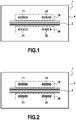
- FIG. 1 and 2 schematically illustrate a rear light 1 according to the invention in two operating modes activated according to the method according to the invention.
- This rear light 1 comprises a box 4 closed by a transparent glass (not shown) in front of optical modules 11, 12, 21, 22 of this rear light.
- the figures 1 and 2 are seen from the front, thus only the illuminating surfaces of these optical modules 11, 12, 21, 22 are represented.
- This first set 10 and this second set 20 of optical modules 11, 12, 21, 22 can be separated for example by a mask or by other optical modules providing another function, such as the town lamp function, represented here by the three horizontal bars referenced 2.
- the optical modules 11, 12 of the first set 10 are each capable of generating a light beam.
- the two light beams obtained perform a first signaling function, such as a rear position light function or a brake light function.
- the first function is a brake light, which will be activated when the vehicle brakes, whether this vehicle is moving forwards or backwards and whether it is in forward or reverse gear.
- This brake light function is represented by the diagonal hatching in the figures 1 and 2 .
- bi-function optical modules 21, 22 are each able to generate two distinct light beams, implemented according to the mode of operation of these bi-function optical modules. 21, 22, and therefore of the operating mode of rear light 1.
- the reverse gear of the vehicle is engaged.
- the dual-function optical modules 21, 22 are controlled to operate according to a first mode of operation, during which the dual-function optical modules 21, 22 each generate a light beam, the two formed beams performing a second signaling function, in this example a reversing light.
- This reversing light function is represented by the vertical hatching on the figure 1 .
- the first set of optical modules 11, 12 can emit a stop light function strong enough for it to be visible from a sufficient distance. In a parking lot, or in a small street, it is not necessary for this stop light to be seen from as far away as on a fast lane.
- the rear light 1 is made in such a way that the optical modules 21, 22 of the second assembly 20 can generate light beams different from those they generate. during the first mode of operation.
- the dual-function optical modules 21, 22 are controlled according to a second mode of operation, in which they will be able to generate additional light beams which will complete the traffic light. stop generated by the first assembly 10, in the event of braking of the vehicle.
- all of the optical modules of the second set 20 are arranged as bi-function optical modules 21, 22. However, it would be possible to produce only one of them in this way. By realizing the two optical modules as bi-function modules, we make the brake light function visible from even further away.
- the complementary light beam of each of the bi-function optical modules 21, 22 has a photometric distribution whose pattern is identical to that of the photometric distribution of the first function.
- a reinforcement of the intensity is therefore obtained by preserving the pattern and the distribution on the photometric grid of the brake light function before it is supplemented by the dual-function optical modules 21, 22.
- the picture 3 illustrates an embodiment of the optical modules 11, 12, 21, 22, of the rear light of the figures 1 and 2 . Only one optical module 11, 21 per set is shown. The following description can be transposed to the other optical modules referenced above 12, 22.
- Each of the optical modules 11, 12 comprises a light guide 19, 29.
- Each of these light guides 19, 29 comprises a diopter of input 14, 24, opposite which is arranged a light-emitting diode 17, 27 (hereinafter LED) so that it emits its light rays towards the corresponding input diopter 14, 24.
- These rays will then pass through the corresponding input interface 14, 24, then be guided, in particular by internal reflection, for example total, inside the light guide 19, 29 corresponding to the faces of this light guide, until 'at an exit diopter terminal forming the illuminating surface 15, 25, of this light guide 19, 29.
- These illuminating surfaces 15 and 25 are the visible image of the optical modules 11, respectively 21, illustrated on the figures 1 and 2 .
- these light guides 19, 29 are in the form of parallelepipedic plates, their illuminating surfaces visible from the front in figures 1 and 2 being rectangular. However, other shapes are possible.
- Each LED 17 associated with a light guide 19 of one of the optical modules of the first set 10, comprises a substrate 16 and a light-emitting element 31 mounted on this substrate facing the input diopter 14.
- This light-emitting element 31 is designed and arranged to emit red light when subjected to an electric current.
- the substrate 16 is itself mounted on an electronic control card 18 of the LED 17.
- the electronic card supplies the light emitting element 31 with current, the latter emits light rays of red color.
- the arrangement of the guide 19 will guide and deflect these rays so that, on leaving, the rays emitted from the illuminating surfaces 15 of the light guides of the first set 10 form a stop light.
- Each LED 27 associated with a light guide 29 of one of the optical modules 21, 22 of the first assembly 20, comprises a substrate 26 and two light-emitting elements 32, 33, mounted on this substrate 26 and facing the diopter input 24 of this light guide 29.
- a first 32 of these light-emitting elements is designed and arranged to emit white light when it is subjected to an electric current.
- a second 33 of these light-emitting elements is designed and arranged to emit red light when it is subjected to an electric current.
- These two light-emitting elements 32 and 32 are mounted on the same substrate 26, so that the LED can be qualified as a bi-chip. Alternatively, it can be two LEDs each mounted on its substrate and placed side by side. coast. In these two cases, the light source will hereinafter be called bi-function LED.
- the substrate 26 is itself mounted on an electronic control board 28 of the bi-function LED 27.
- the electronic control card 28 of this bi-function LED is connected to a control module 30, which, depending on the information signals received by the vehicle, determines the lighting of the optical modules according to the forward gear or the gear rear of the vehicle.
- the control module 30 transmits the setpoint for activating the first light-emitting element 32 of the dual-function LED 27.
- the electronic control card 28 of this dual-function LED 27 then supplies the first element current photoemitter 32, it then emits light rays of white color.
- the arrangement of the light guide 29 will guide and deflect these rays so that, on leaving, the rays emitted from the illuminating surfaces 25 of the light guides of the second set 20 form a regulatory reversing light.
- the control module 30 is also connected to the electronic control card 18 of each LED 17 of the first set 10. In the event of braking, this control module 30 will send the braking instruction to this electronic control card 18 of the first set 10 The latter will then supply the light-emitting element 18, and the first assembly 10 will generate a regulatory stop function. The second set 20 will nevertheless continue to generate a reversing light function.
- the control module 30 If the vehicle is in forward gear, the control module 30 is placed in the second mode of operation. If during this second operating mode, the vehicle brakes, in addition to the braking instruction to the electronic control board 18 of the first assembly 10, the control module 30 transmits the activation instruction of the second light-emitting element 33 of dual-function LED 27. The electronic control card 28 of this dual-function LED 27 then supplies current to the second light-emitting element 33, which then emits red light rays.
- the arrangement of the light guide 29 will guide and deflect these red rays, so that on leaving the rays emitted from the illuminating surfaces 25 of the light guides of the second set 20 are added to the light rays emitted by the surfaces illuminating lights 15 of the first set 10, and together form a so-called reinforced stop light.
- This brake light will thus be more powerful than when the rear light is in the first mode of operation and therefore visible from further away, which is of interest for high-speed travel, in particular on the motorway.
- This rear light and the method according to the invention have therefore made it possible to take advantage, during forward travel, of optical modules serving to signal the reversal of the vehicle when reverse gear is engaged.
- This rear light and this method therefore make it possible to increase the power of the brake light signal without further encumbering the rear light with additional modules.
- the control module 30 can determine whether the vehicle is in reverse gear or forward gear by sensors at the level of the gear lever or by instructions that it receives when the reverse gear or the forward gear is engaged.
- the optical modules of the second set 20 can also be made according to an embodiment illustrated in figure 4 .
- the optical modules 11, 12 of the first set 10 remain identical to those illustrated in picture 3 and are therefore not represented in figure 4 .
- the light guide 129 of each second optical module 121 comprises a first input diopter 124a and a second input diopter 124b, carried respectively by a first branch 129a and a second branch 129b of the light guide 129. These two branches 129a, 129b meet in a common trunk 129c, which carries the exit diopter forming the illuminating surface 125 of the light guide 129.
- first and second input dioptres 124a and 124b are therefore distant and distinct from each other. Opposite each of them is arranged an LED, ie a first LED 127a facing the first input interface 124a and a second LED 127b facing the second input interface 124b.
- Each of these LEDs 127a, 127b comprises a light-emitting element mounted on a corresponding substrate 116, 126.
- the light-emitting element 132 of this first LED 127a is designed and arranged to emit white light when it is subjected to an electric current.
- the light-emitting element 133 of this second LED 127b is designed and arranged to emit red light when it is subjected to an electric current.
- the substrates 116, 126 of these two LEDs 127a, 127b are mounted on the same electronic control board 128.
- the latter is connected to a control module 130, itself connected to the electronic control board(s) 18 of the optical modules 11, 12 of the first set 10.
- this control module 130 will send the braking instruction to this electronic control card 18 of the first assembly 10, as previously described for the picture 3 .
- the control module 130 transmits the setpoint for activating the first LED 127a.
- the electronic control card 128 then supplies the first LED 127a with current.
- the light-emitting element 132 of this first LED then emits light rays of white color, through the first input diopter 124a.
- the arrangement of the light guide 129 will guide and deflect these rays along its first branch 129a, then along its trunk 129c, as far as the exit interface from which they will exit.
- the arrangement of the light guide 129 is such that the white rays emerging from the illuminating surfaces 25 of the light guides of the second set 20 form a reversing light.
- control module 130 can control the first set 10 to generate the brake light, while allowing the second set 20 to generate a reversing light function in parallel.
- the control module 130 if the vehicle is in forward gear, the control module 130 is placed in the second mode of operation. If during this second mode of operation, the vehicle brakes, in addition to the braking instruction to the electronic control card 18 to supply the LEDs of the optical modules of the first set 10, the control module 130 transmits the braking instruction activation of the light-emitting element 133 of the second LED 127b of the optical modules 121 of the second set. The electronic control card 128 of this second LED 127b then supplies its light-emitting element 133 with current, the latter then emits light rays of red color.
- the arrangement of the light guide 129 will guide and deflect these red rays along its second branch 129b, then along its trunk 129c, as far as the exit dioptre from which they will emerge.
- the arrangement of the light guide 129 is such that the illuminating surfaces 25 of the light guides of the second set 20 then form a stop light with the light rays emitted by the illuminating surfaces 15 of the first set 10.
Landscapes
- Engineering & Computer Science (AREA)
- General Engineering & Computer Science (AREA)
- Mechanical Engineering (AREA)
- Physics & Mathematics (AREA)
- Microelectronics & Electronic Packaging (AREA)
- Optics & Photonics (AREA)
- Lighting Device Outwards From Vehicle And Optical Signal (AREA)
- Non-Portable Lighting Devices Or Systems Thereof (AREA)
Claims (14)
- Verfahren zur Steuerung von Optikmodulen (11, 12, 21, 22; 121) einer Rückleuchte (1) eines Fahrzeugs, das Verfahren umfassend die folgenden Schritte:- Aktivieren einer ersten Anordnung (10) eines oder mehrerer Optikmodule (11, 12), wobei die erste Anordnung eine erste Signalisierungsfunktion erzeugt,- wenn der Rückwärtsgang im Fahrzeug eingelegt ist, Aktivieren einer zweiten Anordnung (20) einer oder mehrerer Optikmodule (21, 22; 121) gemäß einem ersten Betriebsmodus, damit die zweite Anordnung eine zweite Signalisierungsfunktion erzeugt, die von der ersten Signalisierungsfunktion gesondert ist,- wenn der Rückwärtsgang im Fahrzeug nicht eingelegt ist, Aktivieren des oder wenigstens eines der Optikmodule der zweiten Anordnung gemäß einem zweiten Betriebsmodus, damit dieses Optikmodul ein ergänzendes Lichtbündel erzeugt, das von dem Lichtbündel gesondert ist, das es im ersten Betriebsmodus emittiert, wobei dieses gesonderte ergänzende Lichtbündel die erste Signalisierungsfunktion ergänzt, wobei das ergänzende Lichtbündel eine photometrische Verteilung aufweist, deren Muster mit jenem der photometrischen Verteilung der ersten Funktion identisch ist.
- Verfahren nach Anspruch 1, wobei die erste Signalisierungsfunktion eine hintere Positionsleuchte oder eine Bremsleuchte ist.
- Verfahren nach einem der Ansprüche 1 bis 2, wobei die zweite Signalisierungsfunktion eine Rückfahrleuchte ist.
- Verfahren nach einem der Ansprüche 1 bis 3, wobei das ergänzende Lichtbündel angeordnet ist, die Leuchtstärke der ersten Signalisierungsfunktion zu verstärken.
- Fahrzeugrückleuchte (1) umfassend:- eine erste Anordnung (10) von einem oder mehreren Optikmodulen (11, 12), wobei das oder die Optikmodule geeignet sind, ein oder mehrere Lichtbündel zu erzeugen, damit die erste Anordnung (10) eine erste Signalisierungsfunktion erzeugt,- eine zweite Anordnung (20) von einem oder mehreren Optikmodulen (21, 22; 121), wobei das oder die Optikmodule geeignet sind, ein oder mehrere Lichtbündel zu erzeugen, damit die zweite Anordnung (20) eine zweite Signalisierungsfunktion erzeugt, die von der ersten Signalisierungsfunktion gesondert ist,dadurch gekennzeichnet, dass das oder wenigstens eins der Optikmodule der zweiten Anordnung, das Bifunktions-Optikmodul (21, 22; 121), so angeordnet ist, dass es alternativ zwei gesonderte Lichtbündel emittieren kann, wobei das erste Lichtbündel die zweite Signalisierungsfunktion ausführt oder an deren Ausführung mitwirkt, und das zweite ergänzende Lichtbündel die erste Signalisierungsfunktion ergänzt, wobei das ergänzende Lichtbündel eine photometrische Verteilung aufweist, deren Muster mit jenem der photometrischen Verteilung der ersten Funktion identisch ist.
- Rückleuchte nach Anspruch 5, wobei wenigstens eins der Optikmodule (11, 12, 21, 22) einen Lichtleiter (19, 29; 129) umfasst, der wenigstens einen Eingangsdiopter (14, 24; 124a, 124b) und wenigstens eine beleuchtende Fläche (15, 25) umfasst, wobei der Lichtleiter so angeordnet ist, dass er die Lichtstrahlen, die von einer Lichtquelle (31, 32; 132, 133) emittiert werden, durch diesen Eingangsdiopter empfangen und diese Lichtstrahlen bis zu dieser beleuchtenden Fläche (15, 25) leiten kann, von wo diese Strahlen austreten, um die erste Signalisierungsfunktion oder die zweite Signalisierungsfunktion zu erzeugen oder an deren Erzeugung mitzuwirken.
- Rückleuchte nach Anspruch 5 oder 6, wobei das Bifunktions-Optikmodul (121) einen Lichtleiter (129) umfasst, der zwei Eingangsdiopter (124a, 124b), die voneinander beabstandet sind, und eine beleuchtende Fläche (125) umfasst, wobei dieser Lichtleiter, der Doppeleingangs-Lichtleiter (129), so angeordnet ist, dass:- einer der Eingangsdiopter, der erste Diopter (124a), das Licht einer Lichtquelle (132) durch diesen Eingangsdiopter empfangen kann,- der andere der Eingangsdiopter, der zweite Diopter (124b), das Licht einer anderen Lichtquelle (133) durch diesen zweiten Eingangsdiopter empfangen kann,- er das Licht von seinen Eingangsdioptern bis zur beleuchtenden Fläche leitet, von wo dieses Licht austritt, um die zweite Signalisierungsfunktion zu erzeugen oder an deren Erzeugung mitzuwirken, oder um die erste Signalisierungsfunktion zu ergänzen.
- Rückleuchte nach Anspruch 7, wobei das Bifunktions-Optikmodul (121) die zwei Lichtquellen unterschiedlicher Stärken und/oder Farben umfasst, wobei eine (132) der Lichtquellen angeordnet ist, durch den ersten Eingangsdiopter (124a) des Doppeleingangs-Lichtleiters (129) zu emittieren, wobei die andere (133) der Lichtquellen angeordnet ist, durch den zweiten Eingangsdiopter (124b) des Doppeleingangs-Lichtleiters (129) zu emittieren.
- Rückleuchte nach Anspruch 8, wobei die Lichtquellen, deren Doppeleingangs-Lichtleiter (129) das Licht empfängt, lichtemittierende Elemente (132, 133) gesonderter Leuchtdioden (127a, 127b) sind.
- Rückleuchte nach Anspruch 6, wobei das Bifunktions-Optikmodul (21) Folgendes umfasst:- einen Lichtleiter (29), der einen Eingangsdiopter (24) und eine beleuchtende Fläche (25) umfasst,- zwei Lichtquellen (32, 33), die angeordnet sind, durch den Eingangsdiopter zu emittieren, wobei die Lichtquellen unterschiedliche Stärken und/oder Farben aufweisen,wobei der Lichtleiter (29) angeordnet ist, das Licht von seinem Eingangsdiopter (24) bis zu dieser beleuchtenden Fläche (25) leitet, von wo dieses Licht austritt, um die zweite Signalisierungsfunktion zu erzeugen oder an deren Erzeugung mitzuwirken, oder um die erste Signalisierungsfunktion zu ergänzen.
- Rückleuchte nach einem der Ansprüche 8 bis 10, wobei eine (33, 133) der Lichtquellen des Bifunktions-Optikmoduls (21, 121) geeignet ist, ein rotes Licht zu emittieren, und die andere (32, 132) der Lichtquellen des Bifunktions-Optikmoduls (21, 121) geeignet ist, ein weißes Licht zu emittieren.
- Rückleuchte nach Anspruch 11, wobei das oder die Optikmodule (11, 12) der ersten Anordnung (10) wenigstens eine Lichtquelle (31) umfassen, die geeignet ist, rotes Licht zu emittieren, so dass das Licht, das von der ersten Anordnung (10) emittiert wird, rot ist.
- Rückleuchte nach einem der Ansprüche 6 bis 12, umfassend ein Steuerungsmodul (30; 130) der Lichtquellen (32, 33; 132, 133) des Bifunktions-Optikmoduls (21, 22; 121), wobei das Steuerungsmodul geeignet ist, eine (33; 133) der Lichtquellen zu aktivieren, wenn sich das Fahrzeug nicht im Rückwärtsgang befindet, und geeignet ist, die andere (32; 132) der Lichtquellen zu aktivieren, wenn das Fahrzeug rückwärts fährt und/oder sich im Rückwärtsgang befindet.
- Verfahren nach einem der Ansprüche 1 bis 4, dadurch gekennzeichnet, dass es durchgeführt wird, um die Optikmodule (11, 12, 21, 22; 121) einer Rückleuchte (1) nach einem der Ansprüche 6 bis 13 zu steuern.
Applications Claiming Priority (1)
| Application Number | Priority Date | Filing Date | Title |
|---|---|---|---|
| FR1550305A FR3031792B1 (fr) | 2015-01-15 | 2015-01-15 | Procede de commande d'un feu arriere de vehicule |
Publications (2)
| Publication Number | Publication Date |
|---|---|
| EP3045801A1 EP3045801A1 (de) | 2016-07-20 |
| EP3045801B1 true EP3045801B1 (de) | 2022-06-29 |
Family
ID=53008652
Family Applications (1)
| Application Number | Title | Priority Date | Filing Date |
|---|---|---|---|
| EP16151123.3A Active EP3045801B1 (de) | 2015-01-15 | 2016-01-13 | Verfahren zur bedienung eines fahrzeugrücklichts und fahrzeugrücklicht |
Country Status (4)
| Country | Link |
|---|---|
| US (1) | US10023109B2 (de) |
| EP (1) | EP3045801B1 (de) |
| CN (1) | CN105799577B (de) |
| FR (1) | FR3031792B1 (de) |
Families Citing this family (10)
| Publication number | Priority date | Publication date | Assignee | Title |
|---|---|---|---|---|
| DE102014118378A1 (de) * | 2014-12-11 | 2016-06-16 | Hella Kgaa Hueck & Co. | Beleuchtungsvorrichtung für Fahrzeuge |
| CN108613099B (zh) * | 2016-12-16 | 2024-02-23 | 市光法雷奥(佛山)汽车照明系统有限公司 | 用于机动车辆的多功能发光装置 |
| JP6938219B2 (ja) * | 2017-05-23 | 2021-09-22 | 株式会社小糸製作所 | 車両用灯具 |
| CN107357002A (zh) * | 2017-08-18 | 2017-11-17 | 嘉兴海拉灯具有限公司 | 一种光导组合及具有该光导组合的车灯 |
| DE102017119500A1 (de) * | 2017-08-25 | 2019-02-28 | Dr. Ing. H.C. F. Porsche Aktiengesellschaft | Beleuchtungseinrichtung |
| CN113639247B (zh) * | 2017-11-20 | 2023-11-28 | 市光法雷奥(佛山)汽车照明系统有限公司 | 光导构件、发光组件、照明装置和车辆 |
| DE102018209303A1 (de) * | 2018-06-12 | 2019-12-12 | Osram Gmbh | Optik, optisches System und Scheinwerfer |
| EP3647654A1 (de) * | 2018-10-31 | 2020-05-06 | Valeo Iluminacion, S.A. | Autobeleuchtungsvorrichtung |
| CN110608414A (zh) * | 2019-09-23 | 2019-12-24 | 华域视觉科技(上海)有限公司 | 信号灯功能复用式分叉聚光器以及汽车 |
| CN110839308A (zh) * | 2019-11-25 | 2020-02-25 | 奇瑞汽车股份有限公司 | 一种汽车尾灯控制系统 |
Family Cites Families (33)
| Publication number | Priority date | Publication date | Assignee | Title |
|---|---|---|---|---|
| SE402431B (sv) * | 1976-07-21 | 1978-07-03 | Saab Scania Ab | Lyktenhet vid ett fordons fremre horn |
| FR2517147A1 (fr) * | 1981-11-25 | 1983-05-27 | Telecommunications Sa | Systeme numerique de transmission d'informations par voie optique dit pluribus optique |
| FR2590351B1 (fr) * | 1985-11-15 | 1988-02-05 | Cibie Projecteurs | Feu de signalisation a double fonction pour vehicule |
| US4859988A (en) * | 1988-05-19 | 1989-08-22 | Emergency Technology, Inc. | Automotive vehicle exterior light flashing circuit |
| DE19753096A1 (de) * | 1997-11-29 | 1999-06-02 | Volkswagen Ag | Kraftfahrzeugleuchte |
| JP2001210111A (ja) * | 2000-01-27 | 2001-08-03 | Koito Mfg Co Ltd | 車輌用灯具 |
| US6243008B1 (en) * | 2000-08-07 | 2001-06-05 | Walter Korabiak | Automobile rear light warning display |
| US6902307B2 (en) * | 2001-05-25 | 2005-06-07 | Illume, L.L.C. | Taillight apparatus and method of making |
| US7119672B2 (en) * | 2004-03-05 | 2006-10-10 | Ramesh Subbaraman | Dynamic vehicle signaling device and system |
| US20050254240A1 (en) * | 2004-05-12 | 2005-11-17 | Lawrence Duwaine W | Multifunction LED taillight |
| WO2007068000A2 (en) * | 2005-12-09 | 2007-06-14 | Abraham Vasant | Apparatus and system for efficient and maneuverable vehicle |
| US20090122566A1 (en) * | 2007-11-13 | 2009-05-14 | Glen Cunningham | Vehicle tail light assembly and method of use |
| EP2269870B1 (de) * | 2009-06-24 | 2012-06-20 | Nxp B.V. | Fahrzeugaußenlichter |
| US8764256B2 (en) * | 2010-10-01 | 2014-07-01 | Magna Mirrors Of America, Inc. | Vehicle exterior mirror system with light module |
| FR2968745B1 (fr) * | 2010-12-14 | 2012-12-07 | Valeo Systemes Thermiques | Temoin lumineux |
| DE102010056313C5 (de) * | 2010-12-27 | 2017-03-16 | Automotive Lighting Reutlingen Gmbh | Beleuchtungseinrichtung eines Kraftfahrzeugs |
| DE102011009100A1 (de) * | 2011-01-21 | 2012-03-15 | Audi Ag | Kraftfahrzeugbeleuchtungseinrichtung zur Innenraumbeleuchtung oder zur Außenbeleuchtung |
| US8569953B2 (en) * | 2011-01-31 | 2013-10-29 | Yao Hung Huang | Multi-function vehicle light assembly |
| US8441194B2 (en) * | 2011-01-31 | 2013-05-14 | Yao-Hung Huang | Multi-function vehicle light assembly |
| US8564205B2 (en) * | 2011-05-23 | 2013-10-22 | General Electric Company | Configurable vehicle solid state lighting |
| US10076995B2 (en) * | 2011-12-07 | 2018-09-18 | Sl Corporation | Automotive lamp |
| US9162613B2 (en) * | 2012-08-29 | 2015-10-20 | Yao Hung Huang | Vehicle rear light assembly |
| DE102012017596A1 (de) * | 2012-09-06 | 2014-03-06 | Volkswagen Aktiengesellschaft | Leuchteinrichtung für ein Fahrzeug |
| DE102012112151B4 (de) | 2012-12-12 | 2023-11-16 | HELLA GmbH & Co. KGaA | Kraftfahrzeugrückleuchte mit zumindest einer Schlusslichtfunktion, einer Blinklichtfunktion und einer Bremslichtfunktion, die einen ersten und mindestens einen zweiten Lichtleiter umfasst |
| FR3002303B1 (fr) * | 2013-02-21 | 2015-03-20 | Valeo Vision | Unite d'eclairage et/ou de signalisation notamment de vehicule automobile |
| FR3002895B1 (fr) * | 2013-03-05 | 2016-12-23 | Peugeot Citroen Automobiles Sa | Dispositif d'indication de changement de direction d'un vehicule, a guide de lumiere et ecran opalin |
| KR20140110593A (ko) * | 2013-03-08 | 2014-09-17 | 현대자동차주식회사 | 램프를 갖는 차량 |
| DE102013105261B4 (de) * | 2013-05-23 | 2022-12-01 | HELLA GmbH & Co. KGaA | Beleuchtungsvorrichtung für Fahrzeuge |
| JP5719884B2 (ja) * | 2013-07-02 | 2015-05-20 | 本田技研工業株式会社 | 車両用灯体 |
| WO2015078865A1 (de) * | 2013-11-28 | 2015-06-04 | Osram Opto Semiconductors Gmbh | Bauelementanordnung und verfahren zum herstellen einer bauelementanordnung |
| KR101620147B1 (ko) * | 2013-12-18 | 2016-05-23 | 현대자동차주식회사 | 차량용 램프의 광원모듈 |
| US9403475B2 (en) * | 2014-07-15 | 2016-08-02 | Lung-Pin Cheng | Rear-view mirror with auxiliary lighting for reverse and open door alert lighting |
| US9981597B2 (en) * | 2015-01-16 | 2018-05-29 | Meyer Products Llc | Method and apparatus for installing and operating an auxiliary lighting system using a vehicle electric plug |
-
2015
- 2015-01-15 FR FR1550305A patent/FR3031792B1/fr active Active
-
2016
- 2016-01-13 EP EP16151123.3A patent/EP3045801B1/de active Active
- 2016-01-14 US US14/995,708 patent/US10023109B2/en active Active
- 2016-01-15 CN CN201610028980.5A patent/CN105799577B/zh active Active
Also Published As
| Publication number | Publication date |
|---|---|
| US20160207450A1 (en) | 2016-07-21 |
| FR3031792A1 (fr) | 2016-07-22 |
| FR3031792B1 (fr) | 2018-08-10 |
| US10023109B2 (en) | 2018-07-17 |
| CN105799577B (zh) | 2020-08-25 |
| CN105799577A (zh) | 2016-07-27 |
| EP3045801A1 (de) | 2016-07-20 |
Similar Documents
| Publication | Publication Date | Title |
|---|---|---|
| EP3045801A1 (de) | Verfahren zur bedienung eines fahrzeugrücklichts und fahrzeugrücklicht | |
| EP3210829B1 (de) | Beleuchtungssystem für den innenraum von einem kraftfahrzeug | |
| EP1895228B1 (de) | Vorrichtung zur Beleuchtung oder Signalisierung vom Typ Hochleistungs-Lichtwellenleiter für Kraftfahrzeuge | |
| EP2317214B1 (de) | Vorrichtung zur Beleuchtung und/oder Signalisierung für Kraftfahrzeuge, die einen Lichtwellenleiter umfasst | |
| EP3002504B1 (de) | Leuchtmodul zur beleuchtung für kraftfahrzeug | |
| EP2521663B1 (de) | Diffraktive signalisierungsvorrichutung für einen rückspiegel mit 2d-/3d-anzeige | |
| EP3002154B1 (de) | Optisches system für kraftfahrzeug | |
| FR3008477A1 (fr) | Lampe pour vehicule | |
| EP3225905A1 (de) | Rückwärtige beleuchtungs- und/oder signalisierungsvorrichtung für kraftfahrzeug, und rücklicht zur beleuchtung und/oder signalisierung, das mit einer solchen vorrichtung ausgestattet ist | |
| FR3030684B1 (fr) | Dispositif lumineux comprenant des sources surfaciques de lumiere | |
| EP3803198A1 (de) | Leuchtmodul für kraftfahrzeug und mit solch einem modul ausgestattete beleuchtungs- und/oder signalvorrichtung | |
| FR3047295A1 (fr) | Dispositif lumineux segmente pour un vehicule automobile utilisant plusieurs guides de lumiere | |
| EP3511608B1 (de) | Optisches modul für ein kraftfahrzeug | |
| EP2846081B1 (de) | Vorrichtung zur Beleuchtung und Signalisierung für Fahrzeuge | |
| WO2016124718A1 (fr) | Module lumineux d'un véhicule compatible au trafic gauche et au trafic droit | |
| EP3030830B1 (de) | Signalisierungs- und/oder beleuchtungsvorrichtung für kraftfahrzeuge | |
| FR3055981B1 (fr) | Controle de faisceau lumineux pixelise | |
| WO2015011378A1 (fr) | Système d'éclairage, notamment pour un organe d'éclairage de véhicule automobile, a carte a circuit imprime inclinée par rapport a la direction d'éclairage | |
| EP2730838B1 (de) | Leuchtmodul für einen Kraftfahzeugscheinwerfer mit mehreren Lichtquellen | |
| US20240264280A1 (en) | Lidar integrated vehicle lights | |
| EP3343531B1 (de) | Informationskommunikationssystem mit einem nutzer in der nähe eines kraftfahrzeugs | |
| FR2995662A1 (fr) | Module et dispositif d'eclairage pour vehicule automobile | |
| EP3054209B1 (de) | Beleuchtungsvorrichtung für kraftfahrzeug | |
| FR3114371A1 (fr) | Dispositif lumineux d’éclairage et de signalisation | |
| FR3048066A1 (fr) | Dispositif lumineux avec une source lumineuse a batonnets lumineux pour differentes fonctions photometriques |
Legal Events
| Date | Code | Title | Description |
|---|---|---|---|
| PUAI | Public reference made under article 153(3) epc to a published international application that has entered the european phase |
Free format text: ORIGINAL CODE: 0009012 |
|
| AK | Designated contracting states |
Kind code of ref document: A1 Designated state(s): AL AT BE BG CH CY CZ DE DK EE ES FI FR GB GR HR HU IE IS IT LI LT LU LV MC MK MT NL NO PL PT RO RS SE SI SK SM TR |
|
| AX | Request for extension of the european patent |
Extension state: BA ME |
|
| RIN1 | Information on inventor provided before grant (corrected) |
Inventor name: FUENTES, MANUEL Inventor name: MARTINEZ, JUAN MANUEL Inventor name: DEL CARMEN MONTANO, MARIA |
|
| STAA | Information on the status of an ep patent application or granted ep patent |
Free format text: STATUS: REQUEST FOR EXAMINATION WAS MADE |
|
| 17P | Request for examination filed |
Effective date: 20161213 |
|
| RBV | Designated contracting states (corrected) |
Designated state(s): AL AT BE BG CH CY CZ DE DK EE ES FI FR GB GR HR HU IE IS IT LI LT LU LV MC MK MT NL NO PL PT RO RS SE SI SK SM TR |
|
| STAA | Information on the status of an ep patent application or granted ep patent |
Free format text: STATUS: EXAMINATION IS IN PROGRESS |
|
| 17Q | First examination report despatched |
Effective date: 20210324 |
|
| REG | Reference to a national code |
Ref country code: DE Ref legal event code: R079 Ref document number: 602016073111 Country of ref document: DE Free format text: PREVIOUS MAIN CLASS: F21S0008100000 Ipc: B60Q0001220000 |
|
| GRAP | Despatch of communication of intention to grant a patent |
Free format text: ORIGINAL CODE: EPIDOSNIGR1 |
|
| STAA | Information on the status of an ep patent application or granted ep patent |
Free format text: STATUS: GRANT OF PATENT IS INTENDED |
|
| RIC1 | Information provided on ipc code assigned before grant |
Ipc: F21S 43/249 20180101ALI20211210BHEP Ipc: F21S 43/247 20180101ALI20211210BHEP Ipc: F21S 43/243 20180101ALI20211210BHEP Ipc: F21S 43/237 20180101ALI20211210BHEP Ipc: F21S 43/14 20180101ALI20211210BHEP Ipc: B60Q 1/44 20060101ALI20211210BHEP Ipc: B60Q 1/30 20060101ALI20211210BHEP Ipc: B60Q 1/26 20060101ALI20211210BHEP Ipc: B60Q 1/22 20060101AFI20211210BHEP |
|
| INTG | Intention to grant announced |
Effective date: 20220110 |
|
| GRAS | Grant fee paid |
Free format text: ORIGINAL CODE: EPIDOSNIGR3 |
|
| GRAA | (expected) grant |
Free format text: ORIGINAL CODE: 0009210 |
|
| STAA | Information on the status of an ep patent application or granted ep patent |
Free format text: STATUS: THE PATENT HAS BEEN GRANTED |
|
| AK | Designated contracting states |
Kind code of ref document: B1 Designated state(s): AL AT BE BG CH CY CZ DE DK EE ES FI FR GB GR HR HU IE IS IT LI LT LU LV MC MK MT NL NO PL PT RO RS SE SI SK SM TR |
|
| REG | Reference to a national code |
Ref country code: GB Ref legal event code: FG4D Free format text: NOT ENGLISH |
|
| REG | Reference to a national code |
Ref country code: CH Ref legal event code: EP |
|
| REG | Reference to a national code |
Ref country code: AT Ref legal event code: REF Ref document number: 1501130 Country of ref document: AT Kind code of ref document: T Effective date: 20220715 |
|
| REG | Reference to a national code |
Ref country code: IE Ref legal event code: FG4D Free format text: LANGUAGE OF EP DOCUMENT: FRENCH |
|
| REG | Reference to a national code |
Ref country code: DE Ref legal event code: R096 Ref document number: 602016073111 Country of ref document: DE |
|
| REG | Reference to a national code |
Ref country code: LT Ref legal event code: MG9D |
|
| PG25 | Lapsed in a contracting state [announced via postgrant information from national office to epo] |
Ref country code: SE Free format text: LAPSE BECAUSE OF FAILURE TO SUBMIT A TRANSLATION OF THE DESCRIPTION OR TO PAY THE FEE WITHIN THE PRESCRIBED TIME-LIMIT Effective date: 20220629 Ref country code: NO Free format text: LAPSE BECAUSE OF FAILURE TO SUBMIT A TRANSLATION OF THE DESCRIPTION OR TO PAY THE FEE WITHIN THE PRESCRIBED TIME-LIMIT Effective date: 20220929 Ref country code: LT Free format text: LAPSE BECAUSE OF FAILURE TO SUBMIT A TRANSLATION OF THE DESCRIPTION OR TO PAY THE FEE WITHIN THE PRESCRIBED TIME-LIMIT Effective date: 20220629 Ref country code: HR Free format text: LAPSE BECAUSE OF FAILURE TO SUBMIT A TRANSLATION OF THE DESCRIPTION OR TO PAY THE FEE WITHIN THE PRESCRIBED TIME-LIMIT Effective date: 20220629 Ref country code: GR Free format text: LAPSE BECAUSE OF FAILURE TO SUBMIT A TRANSLATION OF THE DESCRIPTION OR TO PAY THE FEE WITHIN THE PRESCRIBED TIME-LIMIT Effective date: 20220930 Ref country code: FI Free format text: LAPSE BECAUSE OF FAILURE TO SUBMIT A TRANSLATION OF THE DESCRIPTION OR TO PAY THE FEE WITHIN THE PRESCRIBED TIME-LIMIT Effective date: 20220629 Ref country code: BG Free format text: LAPSE BECAUSE OF FAILURE TO SUBMIT A TRANSLATION OF THE DESCRIPTION OR TO PAY THE FEE WITHIN THE PRESCRIBED TIME-LIMIT Effective date: 20220929 |
|
| REG | Reference to a national code |
Ref country code: NL Ref legal event code: MP Effective date: 20220629 |
|
| REG | Reference to a national code |
Ref country code: AT Ref legal event code: MK05 Ref document number: 1501130 Country of ref document: AT Kind code of ref document: T Effective date: 20220629 |
|
| PG25 | Lapsed in a contracting state [announced via postgrant information from national office to epo] |
Ref country code: RS Free format text: LAPSE BECAUSE OF FAILURE TO SUBMIT A TRANSLATION OF THE DESCRIPTION OR TO PAY THE FEE WITHIN THE PRESCRIBED TIME-LIMIT Effective date: 20220629 Ref country code: LV Free format text: LAPSE BECAUSE OF FAILURE TO SUBMIT A TRANSLATION OF THE DESCRIPTION OR TO PAY THE FEE WITHIN THE PRESCRIBED TIME-LIMIT Effective date: 20220629 |
|
| PG25 | Lapsed in a contracting state [announced via postgrant information from national office to epo] |
Ref country code: NL Free format text: LAPSE BECAUSE OF FAILURE TO SUBMIT A TRANSLATION OF THE DESCRIPTION OR TO PAY THE FEE WITHIN THE PRESCRIBED TIME-LIMIT Effective date: 20220629 |
|
| PG25 | Lapsed in a contracting state [announced via postgrant information from national office to epo] |
Ref country code: SM Free format text: LAPSE BECAUSE OF FAILURE TO SUBMIT A TRANSLATION OF THE DESCRIPTION OR TO PAY THE FEE WITHIN THE PRESCRIBED TIME-LIMIT Effective date: 20220629 Ref country code: SK Free format text: LAPSE BECAUSE OF FAILURE TO SUBMIT A TRANSLATION OF THE DESCRIPTION OR TO PAY THE FEE WITHIN THE PRESCRIBED TIME-LIMIT Effective date: 20220629 Ref country code: RO Free format text: LAPSE BECAUSE OF FAILURE TO SUBMIT A TRANSLATION OF THE DESCRIPTION OR TO PAY THE FEE WITHIN THE PRESCRIBED TIME-LIMIT Effective date: 20220629 Ref country code: PT Free format text: LAPSE BECAUSE OF FAILURE TO SUBMIT A TRANSLATION OF THE DESCRIPTION OR TO PAY THE FEE WITHIN THE PRESCRIBED TIME-LIMIT Effective date: 20221031 Ref country code: ES Free format text: LAPSE BECAUSE OF FAILURE TO SUBMIT A TRANSLATION OF THE DESCRIPTION OR TO PAY THE FEE WITHIN THE PRESCRIBED TIME-LIMIT Effective date: 20220629 Ref country code: EE Free format text: LAPSE BECAUSE OF FAILURE TO SUBMIT A TRANSLATION OF THE DESCRIPTION OR TO PAY THE FEE WITHIN THE PRESCRIBED TIME-LIMIT Effective date: 20220629 Ref country code: AT Free format text: LAPSE BECAUSE OF FAILURE TO SUBMIT A TRANSLATION OF THE DESCRIPTION OR TO PAY THE FEE WITHIN THE PRESCRIBED TIME-LIMIT Effective date: 20220629 |
|
| PG25 | Lapsed in a contracting state [announced via postgrant information from national office to epo] |
Ref country code: PL Free format text: LAPSE BECAUSE OF FAILURE TO SUBMIT A TRANSLATION OF THE DESCRIPTION OR TO PAY THE FEE WITHIN THE PRESCRIBED TIME-LIMIT Effective date: 20220629 Ref country code: IS Free format text: LAPSE BECAUSE OF FAILURE TO SUBMIT A TRANSLATION OF THE DESCRIPTION OR TO PAY THE FEE WITHIN THE PRESCRIBED TIME-LIMIT Effective date: 20221029 |
|
| REG | Reference to a national code |
Ref country code: DE Ref legal event code: R097 Ref document number: 602016073111 Country of ref document: DE |
|
| PG25 | Lapsed in a contracting state [announced via postgrant information from national office to epo] |
Ref country code: AL Free format text: LAPSE BECAUSE OF FAILURE TO SUBMIT A TRANSLATION OF THE DESCRIPTION OR TO PAY THE FEE WITHIN THE PRESCRIBED TIME-LIMIT Effective date: 20220629 |
|
| PG25 | Lapsed in a contracting state [announced via postgrant information from national office to epo] |
Ref country code: DK Free format text: LAPSE BECAUSE OF FAILURE TO SUBMIT A TRANSLATION OF THE DESCRIPTION OR TO PAY THE FEE WITHIN THE PRESCRIBED TIME-LIMIT Effective date: 20220629 Ref country code: CZ Free format text: LAPSE BECAUSE OF FAILURE TO SUBMIT A TRANSLATION OF THE DESCRIPTION OR TO PAY THE FEE WITHIN THE PRESCRIBED TIME-LIMIT Effective date: 20220629 |
|
| PLBE | No opposition filed within time limit |
Free format text: ORIGINAL CODE: 0009261 |
|
| STAA | Information on the status of an ep patent application or granted ep patent |
Free format text: STATUS: NO OPPOSITION FILED WITHIN TIME LIMIT |
|
| 26N | No opposition filed |
Effective date: 20230330 |
|
| P01 | Opt-out of the competence of the unified patent court (upc) registered |
Effective date: 20230629 |
|
| PG25 | Lapsed in a contracting state [announced via postgrant information from national office to epo] |
Ref country code: SI Free format text: LAPSE BECAUSE OF FAILURE TO SUBMIT A TRANSLATION OF THE DESCRIPTION OR TO PAY THE FEE WITHIN THE PRESCRIBED TIME-LIMIT Effective date: 20220629 |
|
| REG | Reference to a national code |
Ref country code: CH Ref legal event code: PL |
|
| GBPC | Gb: european patent ceased through non-payment of renewal fee |
Effective date: 20230113 |
|
| PG25 | Lapsed in a contracting state [announced via postgrant information from national office to epo] |
Ref country code: LU Free format text: LAPSE BECAUSE OF NON-PAYMENT OF DUE FEES Effective date: 20230113 |
|
| REG | Reference to a national code |
Ref country code: BE Ref legal event code: MM Effective date: 20230131 |
|
| PG25 | Lapsed in a contracting state [announced via postgrant information from national office to epo] |
Ref country code: LI Free format text: LAPSE BECAUSE OF NON-PAYMENT OF DUE FEES Effective date: 20230131 Ref country code: GB Free format text: LAPSE BECAUSE OF NON-PAYMENT OF DUE FEES Effective date: 20230113 Ref country code: CH Free format text: LAPSE BECAUSE OF NON-PAYMENT OF DUE FEES Effective date: 20230131 |
|
| PG25 | Lapsed in a contracting state [announced via postgrant information from national office to epo] |
Ref country code: BE Free format text: LAPSE BECAUSE OF NON-PAYMENT OF DUE FEES Effective date: 20230131 |
|
| PG25 | Lapsed in a contracting state [announced via postgrant information from national office to epo] |
Ref country code: IT Free format text: LAPSE BECAUSE OF FAILURE TO SUBMIT A TRANSLATION OF THE DESCRIPTION OR TO PAY THE FEE WITHIN THE PRESCRIBED TIME-LIMIT Effective date: 20220629 Ref country code: IE Free format text: LAPSE BECAUSE OF NON-PAYMENT OF DUE FEES Effective date: 20230113 |
|
| PG25 | Lapsed in a contracting state [announced via postgrant information from national office to epo] |
Ref country code: MC Free format text: LAPSE BECAUSE OF FAILURE TO SUBMIT A TRANSLATION OF THE DESCRIPTION OR TO PAY THE FEE WITHIN THE PRESCRIBED TIME-LIMIT Effective date: 20220629 |
|
| PG25 | Lapsed in a contracting state [announced via postgrant information from national office to epo] |
Ref country code: MC Free format text: LAPSE BECAUSE OF FAILURE TO SUBMIT A TRANSLATION OF THE DESCRIPTION OR TO PAY THE FEE WITHIN THE PRESCRIBED TIME-LIMIT Effective date: 20220629 |
|
| PG25 | Lapsed in a contracting state [announced via postgrant information from national office to epo] |
Ref country code: BG Free format text: LAPSE BECAUSE OF FAILURE TO SUBMIT A TRANSLATION OF THE DESCRIPTION OR TO PAY THE FEE WITHIN THE PRESCRIBED TIME-LIMIT Effective date: 20220629 |
|
| PG25 | Lapsed in a contracting state [announced via postgrant information from national office to epo] |
Ref country code: BG Free format text: LAPSE BECAUSE OF FAILURE TO SUBMIT A TRANSLATION OF THE DESCRIPTION OR TO PAY THE FEE WITHIN THE PRESCRIBED TIME-LIMIT Effective date: 20220629 |
|
| PGFP | Annual fee paid to national office [announced via postgrant information from national office to epo] |
Ref country code: DE Payment date: 20250116 Year of fee payment: 10 |
|
| PGFP | Annual fee paid to national office [announced via postgrant information from national office to epo] |
Ref country code: FR Payment date: 20250130 Year of fee payment: 10 |
|
| PG25 | Lapsed in a contracting state [announced via postgrant information from national office to epo] |
Ref country code: CY Free format text: LAPSE BECAUSE OF FAILURE TO SUBMIT A TRANSLATION OF THE DESCRIPTION OR TO PAY THE FEE WITHIN THE PRESCRIBED TIME-LIMIT; INVALID AB INITIO Effective date: 20160113 |
|
| PG25 | Lapsed in a contracting state [announced via postgrant information from national office to epo] |
Ref country code: HU Free format text: LAPSE BECAUSE OF FAILURE TO SUBMIT A TRANSLATION OF THE DESCRIPTION OR TO PAY THE FEE WITHIN THE PRESCRIBED TIME-LIMIT; INVALID AB INITIO Effective date: 20160113 |
|
| PG25 | Lapsed in a contracting state [announced via postgrant information from national office to epo] |
Ref country code: TR Free format text: LAPSE BECAUSE OF FAILURE TO SUBMIT A TRANSLATION OF THE DESCRIPTION OR TO PAY THE FEE WITHIN THE PRESCRIBED TIME-LIMIT Effective date: 20220629 |