EP3045754B1 - Universelles gleichlaufgelenk - Google Patents
Universelles gleichlaufgelenk Download PDFInfo
- Publication number
- EP3045754B1 EP3045754B1 EP14844277.5A EP14844277A EP3045754B1 EP 3045754 B1 EP3045754 B1 EP 3045754B1 EP 14844277 A EP14844277 A EP 14844277A EP 3045754 B1 EP3045754 B1 EP 3045754B1
- Authority
- EP
- European Patent Office
- Prior art keywords
- joint member
- ball
- torque transmitting
- ball groove
- constant
- Prior art date
- Legal status (The legal status is an assumption and is not a legal conclusion. Google has not performed a legal analysis and makes no representation as to the accuracy of the status listed.)
- Revoked
Links
- 230000005540 biological transmission Effects 0.000 description 4
- 230000007423 decrease Effects 0.000 description 1
- 230000003247 decreasing effect Effects 0.000 description 1
- 230000000694 effects Effects 0.000 description 1
- 238000004519 manufacturing process Methods 0.000 description 1
- 238000012986 modification Methods 0.000 description 1
- 230000004048 modification Effects 0.000 description 1
- 238000005457 optimization Methods 0.000 description 1
- 230000001105 regulatory effect Effects 0.000 description 1
Images

Classifications
-
- F—MECHANICAL ENGINEERING; LIGHTING; HEATING; WEAPONS; BLASTING
- F16—ENGINEERING ELEMENTS AND UNITS; GENERAL MEASURES FOR PRODUCING AND MAINTAINING EFFECTIVE FUNCTIONING OF MACHINES OR INSTALLATIONS; THERMAL INSULATION IN GENERAL
- F16D—COUPLINGS FOR TRANSMITTING ROTATION; CLUTCHES; BRAKES
- F16D3/00—Yielding couplings, i.e. with means permitting movement between the connected parts during the drive
- F16D3/16—Universal joints in which flexibility is produced by means of pivots or sliding or rolling connecting parts
- F16D3/20—Universal joints in which flexibility is produced by means of pivots or sliding or rolling connecting parts one coupling part entering a sleeve of the other coupling part and connected thereto by sliding or rolling members
- F16D3/22—Universal joints in which flexibility is produced by means of pivots or sliding or rolling connecting parts one coupling part entering a sleeve of the other coupling part and connected thereto by sliding or rolling members the rolling members being balls, rollers, or the like, guided in grooves or sockets in both coupling parts
- F16D3/223—Universal joints in which flexibility is produced by means of pivots or sliding or rolling connecting parts one coupling part entering a sleeve of the other coupling part and connected thereto by sliding or rolling members the rolling members being balls, rollers, or the like, guided in grooves or sockets in both coupling parts the rolling members being guided in grooves in both coupling parts
-
- F—MECHANICAL ENGINEERING; LIGHTING; HEATING; WEAPONS; BLASTING
- F16—ENGINEERING ELEMENTS AND UNITS; GENERAL MEASURES FOR PRODUCING AND MAINTAINING EFFECTIVE FUNCTIONING OF MACHINES OR INSTALLATIONS; THERMAL INSULATION IN GENERAL
- F16D—COUPLINGS FOR TRANSMITTING ROTATION; CLUTCHES; BRAKES
- F16D3/00—Yielding couplings, i.e. with means permitting movement between the connected parts during the drive
- F16D3/16—Universal joints in which flexibility is produced by means of pivots or sliding or rolling connecting parts
- F16D3/20—Universal joints in which flexibility is produced by means of pivots or sliding or rolling connecting parts one coupling part entering a sleeve of the other coupling part and connected thereto by sliding or rolling members
- F16D3/22—Universal joints in which flexibility is produced by means of pivots or sliding or rolling connecting parts one coupling part entering a sleeve of the other coupling part and connected thereto by sliding or rolling members the rolling members being balls, rollers, or the like, guided in grooves or sockets in both coupling parts
- F16D3/223—Universal joints in which flexibility is produced by means of pivots or sliding or rolling connecting parts one coupling part entering a sleeve of the other coupling part and connected thereto by sliding or rolling members the rolling members being balls, rollers, or the like, guided in grooves or sockets in both coupling parts the rolling members being guided in grooves in both coupling parts
- F16D3/2237—Universal joints in which flexibility is produced by means of pivots or sliding or rolling connecting parts one coupling part entering a sleeve of the other coupling part and connected thereto by sliding or rolling members the rolling members being balls, rollers, or the like, guided in grooves or sockets in both coupling parts the rolling members being guided in grooves in both coupling parts where the grooves are composed of radii and adjoining straight lines, i.e. undercut free [UF] type joints
-
- F—MECHANICAL ENGINEERING; LIGHTING; HEATING; WEAPONS; BLASTING
- F16—ENGINEERING ELEMENTS AND UNITS; GENERAL MEASURES FOR PRODUCING AND MAINTAINING EFFECTIVE FUNCTIONING OF MACHINES OR INSTALLATIONS; THERMAL INSULATION IN GENERAL
- F16D—COUPLINGS FOR TRANSMITTING ROTATION; CLUTCHES; BRAKES
- F16D3/00—Yielding couplings, i.e. with means permitting movement between the connected parts during the drive
- F16D3/16—Universal joints in which flexibility is produced by means of pivots or sliding or rolling connecting parts
- F16D3/20—Universal joints in which flexibility is produced by means of pivots or sliding or rolling connecting parts one coupling part entering a sleeve of the other coupling part and connected thereto by sliding or rolling members
- F16D3/22—Universal joints in which flexibility is produced by means of pivots or sliding or rolling connecting parts one coupling part entering a sleeve of the other coupling part and connected thereto by sliding or rolling members the rolling members being balls, rollers, or the like, guided in grooves or sockets in both coupling parts
- F16D3/223—Universal joints in which flexibility is produced by means of pivots or sliding or rolling connecting parts one coupling part entering a sleeve of the other coupling part and connected thereto by sliding or rolling members the rolling members being balls, rollers, or the like, guided in grooves or sockets in both coupling parts the rolling members being guided in grooves in both coupling parts
- F16D2003/22303—Details of ball cages
-
- F—MECHANICAL ENGINEERING; LIGHTING; HEATING; WEAPONS; BLASTING
- F16—ENGINEERING ELEMENTS AND UNITS; GENERAL MEASURES FOR PRODUCING AND MAINTAINING EFFECTIVE FUNCTIONING OF MACHINES OR INSTALLATIONS; THERMAL INSULATION IN GENERAL
- F16D—COUPLINGS FOR TRANSMITTING ROTATION; CLUTCHES; BRAKES
- F16D3/00—Yielding couplings, i.e. with means permitting movement between the connected parts during the drive
- F16D3/16—Universal joints in which flexibility is produced by means of pivots or sliding or rolling connecting parts
- F16D3/20—Universal joints in which flexibility is produced by means of pivots or sliding or rolling connecting parts one coupling part entering a sleeve of the other coupling part and connected thereto by sliding or rolling members
- F16D3/22—Universal joints in which flexibility is produced by means of pivots or sliding or rolling connecting parts one coupling part entering a sleeve of the other coupling part and connected thereto by sliding or rolling members the rolling members being balls, rollers, or the like, guided in grooves or sockets in both coupling parts
- F16D3/223—Universal joints in which flexibility is produced by means of pivots or sliding or rolling connecting parts one coupling part entering a sleeve of the other coupling part and connected thereto by sliding or rolling members the rolling members being balls, rollers, or the like, guided in grooves or sockets in both coupling parts the rolling members being guided in grooves in both coupling parts
- F16D2003/22309—Details of grooves
-
- Y—GENERAL TAGGING OF NEW TECHNOLOGICAL DEVELOPMENTS; GENERAL TAGGING OF CROSS-SECTIONAL TECHNOLOGIES SPANNING OVER SEVERAL SECTIONS OF THE IPC; TECHNICAL SUBJECTS COVERED BY FORMER USPC CROSS-REFERENCE ART COLLECTIONS [XRACs] AND DIGESTS
- Y10—TECHNICAL SUBJECTS COVERED BY FORMER USPC
- Y10S—TECHNICAL SUBJECTS COVERED BY FORMER USPC CROSS-REFERENCE ART COLLECTIONS [XRACs] AND DIGESTS
- Y10S464/00—Rotary shafts, gudgeons, housings, and flexible couplings for rotary shafts
- Y10S464/904—Homokinetic coupling
- Y10S464/906—Torque transmitted via radially spaced balls
Definitions
- the present invention relates to a constant-velocity universal joint for vehicles.
- a constant-velocity universal joint comprising the features of the preamble of claim 1 is disclosed in document WO 2011/149005 A1 .
- a constant-velocity universal joint includes an outer joint member having outer ball grooves, an inner joint member having inner ball grooves, torque transmitting balls which are disposed to be guided respectively by a pair of the outer ball groove and the inner ball groove, and a ball cage containing the torque transmitting balls.
- Such a constant-velocity universal joint may be interposed between a transmission and a driving wheel to perform a function of transmitting torque.
- the ball grooves of the constant-velocity universal joint may be formed by joining portions having different shapes so as to have double shapes and to have a high articulation angle (e.g., more than 50 degrees).
- a ratio O/H of an offset value O which is a distance between an inflection point of an outer ball groove and a line connecting centers of the torque transmitting balls in a state that an outer joint member and an inner joint member form 0 angle and a distance H between a center line of an inner joint member and a center of a ball in a state that an outer joint member and an inner joint member form 0 angle is generally within a range of 0.13 to 0.15.
- the present invention has been made in an effort to provide a constant-velocity universal joint of a high-articulation angle which can reduce a power loss through the optimization of the above-described ratio O/H.
- a constant-velocity universal joint includes: an outer joint member having a plurality of outer ball grooves; an inner joint member having a plurality of inner ball grooves respectively corresponding to the plurality of the outer ball grooves; a plurality of torque transmitting balls which are respectively guided by a pair of the outer ball groove and the inner ball groove; and a ball cage containing the plurality of the torque transmitting balls.
- the outer ball groove and the inner ball groove respectively have a double shape which is formed by a connection of different shapes, and a ratio O/H of an offset value O which is a distance between an inflection point of the outer ball groove and a line connecting centers of the torque transmitting balls in a state that the outer joint member and the inner joint member form 0 angle and a distance H between a center line of the inner joint member and a center of the torque
- the ball cage may be formed such that a contact point contacting the torque transmitting ball is positioned at a point between 1/8 and 1/12 from an inner end to an outer end of a contacting surface
- the inner joint member may be formed to be able to be articulated more than 50 degrees with respect to the outer joint member.
- the inflection point is offset toward an open side of the outer joint member from a line connecting centers of the torque transmitting balls.
- the power transmission efficiency can be enhanced and at the same time the locking can be prevented.
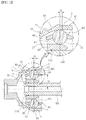
- a constant-velocity universal joint includes an outer joint member 10 and an inner joint member 20.
- the constant-velocity universal joint may perform a function of transmitting power of a transmission to a driving wheel, and the outer joint member 10 may be connected to a driving wheel and the inner joint member 20 may be connected to a transmission via a connecting shaft 100.
- the inner joint member 20 is connected to the connecting shaft 100 so as to rotate therewith, and a fixing ring 110 may be interposed between the inner joint member 20 and the connecting shaft 100 for the fixing along a shaft direction.
- the constant-velocity universal joint may be a constant-velocity universal joint with a high articulation angle (e.g., more than 50 degrees) between the outer joint member 10 and the inner joint member 20.
- a high articulation angle e.g., more than 50 degrees
- the outer joint member 10 may have a shape in which one side thereof are opened so as to receive the inner joint member 20, and the inner joint member 20 is disposed within the outer joint member 10 in a state of being rotatable in a predetermined angle.
- a plurality of outer ball grooves 11 are formed on an inner surface of the outer joint member 10 in a circumferential direction, and a plurality of inner ball grooves 21 are formed on an outer surface of the inner joint member 20 in a circumferential direction.
- a plurality of torque transmitting balls 30 are respectively disposed so as to be guided by a pair of the outer ball groove 11 and the inner ball groove 21. That is, the outer ball groove 11 and the inner ball groove 21 cooperatively operate as a pair, and cooperatively receive the torque transmitting ball 30. Accordingly, the respective torque transmitting ball 30 is disposed in a space formed by a pair of the outer ball groove 11 and the inner ball groove 21 to be movable in a predetermined range to perform a torque transmitting function.
- the torque transmitting ball 30 is contained in a ball cage 40.
- the ball cage includes a plurality of windows 41 for containing the plurality of torque transmitting balls 30.
- the ball cage 40 is interposed between the outer joint member 10 and the inner joint member 10 and may have a ring shape generally, and the respective window 41 may be formed by being perforated in a radial direction.
- the outer ball groove 11 and the inner ball groove 21 are respectively formed by a connection of two different shapes so as to have a double shape. That is, the outer ball groove 11 includes a portion S1 having a first shape and a portion S2 having a second shape which is different from the first shape, and similarly the inner ball groove 21 is formed by a combination of two portions having different shapes so as to have a double shape. At this time, the arrangement of the two portions having different shapes of the inner ball groove 21 is opposite to that of the outer ball groove 11.
- a ratio O/H of an offset value O which is a distance between an inflection point C of the outer ball groove 11 and a line connecting centers BC of the torque transmitting balls 30 in a state that the outer joint member 10 and the inner joint member 20 form 0 angle and a distance H between a center line of the inner joint member 20 and a center of the torque transmitting ball 30 in a state that the outer joint member 10 and the inner joint member 20 form 0 angle (i.e., the state shown in FIG. 1 ) is within a range of 0.07 to 0.11.
- the inflection point C means a point where the two portions S1 and S2 having different shapes meet.
- the inflection point C may be offset toward an open side (the right side in FIG. 1 ) of the outer joint member 10 from a line connecting the centers of the torque transmitting balls 30.
- a linear portion of the outer joint member 10 may be widened less as it goes to the open side compared to the opposite offset direction, the dimensional size of the outer circumference of the outer joint member 10 can be decreased, and accordingly the weight and the size of the total package can be reduced.
- the thickness of the ball cage 40 for restricting the torque transmitting balls should increases more, and the height of a portion which supports the torque transmitting ball decreases so that the ball groove may be crushed, however these problems may be prevented by the offset direction of the embodiment of the present invention.
- the ratio O/H of the two values is within the range of 0.07 to 0.11
- the lower bound 0.07 is a minimum value for preventing locking in consideration of a dimension clearance (approximately 20 ⁇ m) for manufacturing and assembling of the product
- the upper bound 0.11 is a value for achieving an increase of an efficiency of about 5% than the conventional offset ratio (approximately 0.13 to 0.15).
- an embodiment of the present invention is based on discovering the fact that the torque transmitting efficiency varies depending on a ratio O/H of an offset value O which is a distance between an inflection point C of the outer ball groove 11 and a line connecting centers BC of the torque transmitting balls 30 in a state that the outer joint member 10 and the inner joint member 20 form 0 angle and a distance H between a center line of the inner joint member 20 and a center of the torque transmitting ball 30 in a state that the outer joint member 10 and the inner joint member 20 form 0 angle, and this ratio is optimally set to select the range in which the torque transmitting efficiency can be increased and the locking can be prevented.
- the heights OH and IH of the side ends of the outer ball groove 11 and the inner ball groove 21 which restrict the torque transmitting ball 30 may be more than 2/3 of the radius BR of the torque transmitting ball 30.
- the reason of this is that a margin outside the contacting point of the ball can exist so as to prevent a deformation of the groove due to the torque transmitting ball 30 when a load acts in a contacting angle of 30 to 40 degrees of the torque transmitting ball 30.
- the ball cage 40 may be formed such that a contact point contacting the torque transmitting ball 30 may be positioned at a point between 1/8 and 1/12 from an inner end CI to an outer end CO of a contacting surface. That is, in FIG. 3 , a distance between the inner end CI of the contacting surface of the ball cage 40 and the ball contacting point is 1/8 to 1/12 of a distance of the inner end CI and the outer end CO of the contacting surface of the ball cage 40. Further, according to an embodiment of the present invention, a circumferential space for the ball cage 40 may be 1.2 to 1.4 times of the total rotational direction of the torque transmitting ball 30.
- the torque transmitting ball 30 moves in an 8-shape of an improper fraction, and in order to achieve an articulation of 50 degrees it is designed that the contact (at 0 degree) of the ball cage 40 and the torque transmitting ball 30 is downwardly. Due to these values a high articulation angle can be achieved.
- the present invention relates to a constant-velocity joint and can be applied to a part of a vehicle, so it has an industrial applicability.
Landscapes
- Engineering & Computer Science (AREA)
- General Engineering & Computer Science (AREA)
- Mechanical Engineering (AREA)
- Rolling Contact Bearings (AREA)
- Transmission Devices (AREA)
- Testing Of Devices, Machine Parts, Or Other Structures Thereof (AREA)
- Retarders (AREA)
- Steering Controls (AREA)
- Motor Power Transmission Devices (AREA)
Claims (2)
- Universal-Gleichlaufgelenk, umfassend:ein äußeres Gelenkelement (10) mit einer Vielzahl von äußeren Kugelrillen (11);ein inneres Gelenkelement (20) mit einer Vielzahl von inneren Kugelrillen (21), die jeweils der Vielzahl der äußeren Kugelrillen (11) entsprechen;eine Vielzahl von Drehmomentübertragungskugeln (30), die jeweils durch ein Paar aus äußerer Kugelrille (11) und innerer Kugelrille (21) geführt sind; undeinen Kugelkäfig (40), der die Vielzahl der Drehmomentübertragungskugeln (30) enthält,wobei die äußere Kugelrille (11) und die innere Kugelrille (21) jeweils eine Doppelform aufweisen, die durch eine Verbindung verschiedener Formen (S1, S2) gebildet ist,dadurch gekennzeichnet, dassein Verhältnis (O/H) eines Versatzwertes (O), der ein Abstand zwischen einem Wendepunkt (C) der äußeren Kugelrille (11) und einer Linie, die Mittelpunkte (BC) der Drehmomentübertragungskugeln (30) in einem Zustand verbindet, in welchem das äußere Gelenkelement (10) und das innere Gelenkelement (20) einen Winkel 0 bilden, und eines Abstandes (H) zwischen einer Mittellinie des inneren Gelenkelements (20) und einer Mitte (BC) der Drehmomentübertragungskugel (30) in einem Zustand, in welchem das äußere Gelenkelement (10) und das innere Gelenkelement (20) einen Winkel 0 bilden, in einem Bereich von 0,07 bis 0,11 liegt,wobei der Wendepunkt (C) von einer Linie, die Mittelpunkte (BC) der Drehmomentübertragungskugeln (30) verbindet, zu einer offenen Seite des äußeren Gelenkelements (10) hin versetzt ist.
- Universal-Gleichlaufgelenk nach Anspruch 1, wobei der Kugelkäfig (40) so ausgebildet ist, dass ein Berührungspunkt, der die Drehmomentübertragungskugel (30) berührt, an einem Punkt zwischen 1/8 und 1/12 von einem inneren Ende (CI) zu einem äußeren Ende (CO) einer Berührungsfläche positioniert ist.
Applications Claiming Priority (2)
| Application Number | Priority Date | Filing Date | Title |
|---|---|---|---|
| KR1020130109257A KR101467913B1 (ko) | 2013-09-11 | 2013-09-11 | 등속 유니버설 조인트 |
| PCT/KR2014/008469 WO2015037915A1 (ko) | 2013-09-11 | 2014-09-11 | 등속 유니버설 조인트 |
Publications (3)
| Publication Number | Publication Date |
|---|---|
| EP3045754A1 EP3045754A1 (de) | 2016-07-20 |
| EP3045754A4 EP3045754A4 (de) | 2017-06-14 |
| EP3045754B1 true EP3045754B1 (de) | 2019-12-18 |
Family
ID=52665947
Family Applications (1)
| Application Number | Title | Priority Date | Filing Date |
|---|---|---|---|
| EP14844277.5A Revoked EP3045754B1 (de) | 2013-09-11 | 2014-09-11 | Universelles gleichlaufgelenk |
Country Status (6)
| Country | Link |
|---|---|
| US (1) | US10082182B2 (de) |
| EP (1) | EP3045754B1 (de) |
| JP (1) | JP6125732B2 (de) |
| KR (1) | KR101467913B1 (de) |
| CN (1) | CN105593549B (de) |
| WO (1) | WO2015037915A1 (de) |
Citations (6)
| Publication number | Priority date | Publication date | Assignee | Title |
|---|---|---|---|---|
| EP0802341A1 (de) | 1995-12-26 | 1997-10-22 | Ntn Corporation | Homokinetisches kreuzgelenk |
| JP2001097063A (ja) | 1999-09-30 | 2001-04-10 | Ntn Corp | Atv用ドライブアクスル |
| US6431988B1 (en) | 1999-09-17 | 2002-08-13 | Ntn Corporation | Fixed type constant velocity joint and assembling method therefor |
| EP1512879A1 (de) | 2003-09-04 | 2005-03-09 | Ntn Corporation | Gleichlauffestgelenk |
| EP2594820A1 (de) | 2010-07-15 | 2013-05-22 | JTEKT Corporation | Gleichlauf-kugelgelenk |
| EP2594821A2 (de) | 2011-11-16 | 2013-05-22 | Hyundai Wia Corporation | Kugelgleichlaufgelenk für ein Fahrzeug |
Family Cites Families (6)
| Publication number | Priority date | Publication date | Assignee | Title |
|---|---|---|---|---|
| JP3859267B2 (ja) * | 1996-05-28 | 2006-12-20 | Ntn株式会社 | 固定型等速自在継手 |
| DE19706864C1 (de) * | 1997-02-21 | 1998-06-25 | Loehr & Bromkamp Gmbh | Gleichlaufdrehgelenk |
| WO2003064876A2 (en) * | 2002-01-31 | 2003-08-07 | Delphi Technologies, Inc. | Constant velocity joint |
| JP4133415B2 (ja) * | 2003-02-18 | 2008-08-13 | Ntn株式会社 | 固定型等速自在継手 |
| JP2005214344A (ja) * | 2004-01-30 | 2005-08-11 | Ntn Corp | 固定型等速自在継手 |
| JP5602497B2 (ja) * | 2010-05-27 | 2014-10-08 | Ntn株式会社 | 固定式等速自在継手 |
-
2013
- 2013-09-11 KR KR1020130109257A patent/KR101467913B1/ko active Active
-
2014
- 2014-09-11 WO PCT/KR2014/008469 patent/WO2015037915A1/ko not_active Ceased
- 2014-09-11 US US15/021,229 patent/US10082182B2/en active Active
- 2014-09-11 CN CN201480050112.6A patent/CN105593549B/zh active Active
- 2014-09-11 JP JP2016542635A patent/JP6125732B2/ja active Active
- 2014-09-11 EP EP14844277.5A patent/EP3045754B1/de not_active Revoked
Patent Citations (6)
| Publication number | Priority date | Publication date | Assignee | Title |
|---|---|---|---|---|
| EP0802341A1 (de) | 1995-12-26 | 1997-10-22 | Ntn Corporation | Homokinetisches kreuzgelenk |
| US6431988B1 (en) | 1999-09-17 | 2002-08-13 | Ntn Corporation | Fixed type constant velocity joint and assembling method therefor |
| JP2001097063A (ja) | 1999-09-30 | 2001-04-10 | Ntn Corp | Atv用ドライブアクスル |
| EP1512879A1 (de) | 2003-09-04 | 2005-03-09 | Ntn Corporation | Gleichlauffestgelenk |
| EP2594820A1 (de) | 2010-07-15 | 2013-05-22 | JTEKT Corporation | Gleichlauf-kugelgelenk |
| EP2594821A2 (de) | 2011-11-16 | 2013-05-22 | Hyundai Wia Corporation | Kugelgleichlaufgelenk für ein Fahrzeug |
Also Published As
| Publication number | Publication date |
|---|---|
| WO2015037915A1 (ko) | 2015-03-19 |
| KR101467913B1 (ko) | 2014-12-02 |
| JP2016531259A (ja) | 2016-10-06 |
| EP3045754A1 (de) | 2016-07-20 |
| CN105593549B (zh) | 2018-11-16 |
| US10082182B2 (en) | 2018-09-25 |
| CN105593549A (zh) | 2016-05-18 |
| US20160223027A1 (en) | 2016-08-04 |
| EP3045754A4 (de) | 2017-06-14 |
| JP6125732B2 (ja) | 2017-05-10 |
Similar Documents
| Publication | Publication Date | Title |
|---|---|---|
| KR101024883B1 (ko) | 트리포드형 등속 조인트 | |
| EP2535611A1 (de) | Dreibein mit gleichlaufschiebegelenk | |
| US7704149B2 (en) | Fixed type constant velocity joint | |
| EP2831437B1 (de) | Gleichlaufgelenk | |
| JP7188124B2 (ja) | 等速自在継手 | |
| EP3045754B1 (de) | Universelles gleichlaufgelenk | |
| WO2010064577A1 (ja) | 固定型等速自在継手 | |
| JP2017194066A (ja) | プロペラシャフト | |
| KR20090101168A (ko) | 밀봉 링을 구비한 볼-앤드-소켓 조인트 | |
| JP2011231792A (ja) | 摺動式等速自在継手およびその外側継手部材のしごき加工方法 | |
| US20120010005A1 (en) | Cross groove-type constant-velocity universal joint | |
| KR101726979B1 (ko) | 유니버설 조인트를 위한 조인트 요크 및 유니버설 조인트 | |
| US8323116B2 (en) | Universal joint | |
| CN104334900A (zh) | 用于机动车辆的从动车轴传动装置 | |
| JP5834968B2 (ja) | 十字軸式自在継手 | |
| EP4245640B1 (de) | Lenkwinkelbegrenzungsmechanismus und fahrzeuglenksystem und fahrzeug damit | |
| EP3418597B1 (de) | Stationäres universelles gleichlaufgelenk | |
| US8393972B2 (en) | Torsional vibration damper | |
| JP4879501B2 (ja) | 高角固定式等速自在継手 | |
| US9618053B2 (en) | Universal joint | |
| EP2592293B1 (de) | Gleichlauf-kugelgelenk | |
| US20120157216A1 (en) | Sliding type tripod constant velocity joint | |
| JP7135756B2 (ja) | 等速自在継手 | |
| JP6716948B2 (ja) | 十字軸継手用ヨーク、十字軸継手 | |
| JP5983812B2 (ja) | 十字軸式自在継手 |
Legal Events
| Date | Code | Title | Description |
|---|---|---|---|
| PUAI | Public reference made under article 153(3) epc to a published international application that has entered the european phase |
Free format text: ORIGINAL CODE: 0009012 |
|
| 17P | Request for examination filed |
Effective date: 20160406 |
|
| AK | Designated contracting states |
Kind code of ref document: A1 Designated state(s): AL AT BE BG CH CY CZ DE DK EE ES FI FR GB GR HR HU IE IS IT LI LT LU LV MC MK MT NL NO PL PT RO RS SE SI SK SM TR |
|
| AX | Request for extension of the european patent |
Extension state: BA ME |
|
| DAX | Request for extension of the european patent (deleted) | ||
| A4 | Supplementary search report drawn up and despatched |
Effective date: 20170515 |
|
| RIC1 | Information provided on ipc code assigned before grant |
Ipc: F16D 3/20 20060101AFI20170509BHEP Ipc: F16D 3/22 20060101ALI20170509BHEP Ipc: F16D 3/2237 20110101ALI20170509BHEP |
|
| RAP1 | Party data changed (applicant data changed or rights of an application transferred) |
Owner name: ERAE AMS CO., LTD. |
|
| RIC1 | Information provided on ipc code assigned before grant |
Ipc: F16D 3/22 20060101ALI20190529BHEP Ipc: F16D 3/2237 20110101ALI20190529BHEP Ipc: F16D 3/20 20060101AFI20190529BHEP |
|
| GRAP | Despatch of communication of intention to grant a patent |
Free format text: ORIGINAL CODE: EPIDOSNIGR1 |
|
| STAA | Information on the status of an ep patent application or granted ep patent |
Free format text: STATUS: GRANT OF PATENT IS INTENDED |
|
| INTG | Intention to grant announced |
Effective date: 20190711 |
|
| GRAS | Grant fee paid |
Free format text: ORIGINAL CODE: EPIDOSNIGR3 |
|
| GRAA | (expected) grant |
Free format text: ORIGINAL CODE: 0009210 |
|
| STAA | Information on the status of an ep patent application or granted ep patent |
Free format text: STATUS: THE PATENT HAS BEEN GRANTED |
|
| AK | Designated contracting states |
Kind code of ref document: B1 Designated state(s): AL AT BE BG CH CY CZ DE DK EE ES FI FR GB GR HR HU IE IS IT LI LT LU LV MC MK MT NL NO PL PT RO RS SE SI SK SM TR |
|
| REG | Reference to a national code |
Ref country code: CH Ref legal event code: EP |
|
| REG | Reference to a national code |
Ref country code: DE Ref legal event code: R096 Ref document number: 602014058718 Country of ref document: DE |
|
| REG | Reference to a national code |
Ref country code: IE Ref legal event code: FG4D |
|
| REG | Reference to a national code |
Ref country code: AT Ref legal event code: REF Ref document number: 1214929 Country of ref document: AT Kind code of ref document: T Effective date: 20200115 |
|
| REG | Reference to a national code |
Ref country code: NL Ref legal event code: MP Effective date: 20191218 |
|
| PG25 | Lapsed in a contracting state [announced via postgrant information from national office to epo] |
Ref country code: SE Free format text: LAPSE BECAUSE OF FAILURE TO SUBMIT A TRANSLATION OF THE DESCRIPTION OR TO PAY THE FEE WITHIN THE PRESCRIBED TIME-LIMIT Effective date: 20191218 Ref country code: LV Free format text: LAPSE BECAUSE OF FAILURE TO SUBMIT A TRANSLATION OF THE DESCRIPTION OR TO PAY THE FEE WITHIN THE PRESCRIBED TIME-LIMIT Effective date: 20191218 Ref country code: GR Free format text: LAPSE BECAUSE OF FAILURE TO SUBMIT A TRANSLATION OF THE DESCRIPTION OR TO PAY THE FEE WITHIN THE PRESCRIBED TIME-LIMIT Effective date: 20200319 Ref country code: BG Free format text: LAPSE BECAUSE OF FAILURE TO SUBMIT A TRANSLATION OF THE DESCRIPTION OR TO PAY THE FEE WITHIN THE PRESCRIBED TIME-LIMIT Effective date: 20200318 Ref country code: FI Free format text: LAPSE BECAUSE OF FAILURE TO SUBMIT A TRANSLATION OF THE DESCRIPTION OR TO PAY THE FEE WITHIN THE PRESCRIBED TIME-LIMIT Effective date: 20191218 Ref country code: NO Free format text: LAPSE BECAUSE OF FAILURE TO SUBMIT A TRANSLATION OF THE DESCRIPTION OR TO PAY THE FEE WITHIN THE PRESCRIBED TIME-LIMIT Effective date: 20200318 Ref country code: LT Free format text: LAPSE BECAUSE OF FAILURE TO SUBMIT A TRANSLATION OF THE DESCRIPTION OR TO PAY THE FEE WITHIN THE PRESCRIBED TIME-LIMIT Effective date: 20191218 |
|
| REG | Reference to a national code |
Ref country code: LT Ref legal event code: MG4D |
|
| PG25 | Lapsed in a contracting state [announced via postgrant information from national office to epo] |
Ref country code: HR Free format text: LAPSE BECAUSE OF FAILURE TO SUBMIT A TRANSLATION OF THE DESCRIPTION OR TO PAY THE FEE WITHIN THE PRESCRIBED TIME-LIMIT Effective date: 20191218 Ref country code: RS Free format text: LAPSE BECAUSE OF FAILURE TO SUBMIT A TRANSLATION OF THE DESCRIPTION OR TO PAY THE FEE WITHIN THE PRESCRIBED TIME-LIMIT Effective date: 20191218 |
|
| PG25 | Lapsed in a contracting state [announced via postgrant information from national office to epo] |
Ref country code: AL Free format text: LAPSE BECAUSE OF FAILURE TO SUBMIT A TRANSLATION OF THE DESCRIPTION OR TO PAY THE FEE WITHIN THE PRESCRIBED TIME-LIMIT Effective date: 20191218 |
|
| PG25 | Lapsed in a contracting state [announced via postgrant information from national office to epo] |
Ref country code: RO Free format text: LAPSE BECAUSE OF FAILURE TO SUBMIT A TRANSLATION OF THE DESCRIPTION OR TO PAY THE FEE WITHIN THE PRESCRIBED TIME-LIMIT Effective date: 20191218 Ref country code: CZ Free format text: LAPSE BECAUSE OF FAILURE TO SUBMIT A TRANSLATION OF THE DESCRIPTION OR TO PAY THE FEE WITHIN THE PRESCRIBED TIME-LIMIT Effective date: 20191218 Ref country code: EE Free format text: LAPSE BECAUSE OF FAILURE TO SUBMIT A TRANSLATION OF THE DESCRIPTION OR TO PAY THE FEE WITHIN THE PRESCRIBED TIME-LIMIT Effective date: 20191218 Ref country code: PT Free format text: LAPSE BECAUSE OF FAILURE TO SUBMIT A TRANSLATION OF THE DESCRIPTION OR TO PAY THE FEE WITHIN THE PRESCRIBED TIME-LIMIT Effective date: 20200513 Ref country code: NL Free format text: LAPSE BECAUSE OF FAILURE TO SUBMIT A TRANSLATION OF THE DESCRIPTION OR TO PAY THE FEE WITHIN THE PRESCRIBED TIME-LIMIT Effective date: 20191218 |
|
| PG25 | Lapsed in a contracting state [announced via postgrant information from national office to epo] |
Ref country code: SM Free format text: LAPSE BECAUSE OF FAILURE TO SUBMIT A TRANSLATION OF THE DESCRIPTION OR TO PAY THE FEE WITHIN THE PRESCRIBED TIME-LIMIT Effective date: 20191218 Ref country code: SK Free format text: LAPSE BECAUSE OF FAILURE TO SUBMIT A TRANSLATION OF THE DESCRIPTION OR TO PAY THE FEE WITHIN THE PRESCRIBED TIME-LIMIT Effective date: 20191218 Ref country code: IS Free format text: LAPSE BECAUSE OF FAILURE TO SUBMIT A TRANSLATION OF THE DESCRIPTION OR TO PAY THE FEE WITHIN THE PRESCRIBED TIME-LIMIT Effective date: 20200418 |
|
| REG | Reference to a national code |
Ref country code: DE Ref legal event code: R026 Ref document number: 602014058718 Country of ref document: DE |
|
| PLBI | Opposition filed |
Free format text: ORIGINAL CODE: 0009260 |
|
| PLAX | Notice of opposition and request to file observation + time limit sent |
Free format text: ORIGINAL CODE: EPIDOSNOBS2 |
|
| 26 | Opposition filed |
Opponent name: NTN CORPORATION Effective date: 20200907 |
|
| REG | Reference to a national code |
Ref country code: AT Ref legal event code: MK05 Ref document number: 1214929 Country of ref document: AT Kind code of ref document: T Effective date: 20191218 |
|
| PG25 | Lapsed in a contracting state [announced via postgrant information from national office to epo] |
Ref country code: DK Free format text: LAPSE BECAUSE OF FAILURE TO SUBMIT A TRANSLATION OF THE DESCRIPTION OR TO PAY THE FEE WITHIN THE PRESCRIBED TIME-LIMIT Effective date: 20191218 Ref country code: ES Free format text: LAPSE BECAUSE OF FAILURE TO SUBMIT A TRANSLATION OF THE DESCRIPTION OR TO PAY THE FEE WITHIN THE PRESCRIBED TIME-LIMIT Effective date: 20191218 |
|
| PG25 | Lapsed in a contracting state [announced via postgrant information from national office to epo] |
Ref country code: AT Free format text: LAPSE BECAUSE OF FAILURE TO SUBMIT A TRANSLATION OF THE DESCRIPTION OR TO PAY THE FEE WITHIN THE PRESCRIBED TIME-LIMIT Effective date: 20191218 Ref country code: SI Free format text: LAPSE BECAUSE OF FAILURE TO SUBMIT A TRANSLATION OF THE DESCRIPTION OR TO PAY THE FEE WITHIN THE PRESCRIBED TIME-LIMIT Effective date: 20191218 |
|
| PLBB | Reply of patent proprietor to notice(s) of opposition received |
Free format text: ORIGINAL CODE: EPIDOSNOBS3 |
|
| PG25 | Lapsed in a contracting state [announced via postgrant information from national office to epo] |
Ref country code: PL Free format text: LAPSE BECAUSE OF FAILURE TO SUBMIT A TRANSLATION OF THE DESCRIPTION OR TO PAY THE FEE WITHIN THE PRESCRIBED TIME-LIMIT Effective date: 20191218 |
|
| PG25 | Lapsed in a contracting state [announced via postgrant information from national office to epo] |
Ref country code: MC Free format text: LAPSE BECAUSE OF FAILURE TO SUBMIT A TRANSLATION OF THE DESCRIPTION OR TO PAY THE FEE WITHIN THE PRESCRIBED TIME-LIMIT Effective date: 20191218 |
|
| REG | Reference to a national code |
Ref country code: CH Ref legal event code: PL |
|
| REG | Reference to a national code |
Ref country code: BE Ref legal event code: MM Effective date: 20200930 |
|
| PG25 | Lapsed in a contracting state [announced via postgrant information from national office to epo] |
Ref country code: LU Free format text: LAPSE BECAUSE OF NON-PAYMENT OF DUE FEES Effective date: 20200911 |
|
| PG25 | Lapsed in a contracting state [announced via postgrant information from national office to epo] |
Ref country code: IE Free format text: LAPSE BECAUSE OF NON-PAYMENT OF DUE FEES Effective date: 20200911 Ref country code: LI Free format text: LAPSE BECAUSE OF NON-PAYMENT OF DUE FEES Effective date: 20200930 Ref country code: CH Free format text: LAPSE BECAUSE OF NON-PAYMENT OF DUE FEES Effective date: 20200930 Ref country code: BE Free format text: LAPSE BECAUSE OF NON-PAYMENT OF DUE FEES Effective date: 20200930 |
|
| PG25 | Lapsed in a contracting state [announced via postgrant information from national office to epo] |
Ref country code: TR Free format text: LAPSE BECAUSE OF FAILURE TO SUBMIT A TRANSLATION OF THE DESCRIPTION OR TO PAY THE FEE WITHIN THE PRESCRIBED TIME-LIMIT Effective date: 20191218 Ref country code: MT Free format text: LAPSE BECAUSE OF FAILURE TO SUBMIT A TRANSLATION OF THE DESCRIPTION OR TO PAY THE FEE WITHIN THE PRESCRIBED TIME-LIMIT Effective date: 20191218 Ref country code: CY Free format text: LAPSE BECAUSE OF FAILURE TO SUBMIT A TRANSLATION OF THE DESCRIPTION OR TO PAY THE FEE WITHIN THE PRESCRIBED TIME-LIMIT Effective date: 20191218 |
|
| PG25 | Lapsed in a contracting state [announced via postgrant information from national office to epo] |
Ref country code: MK Free format text: LAPSE BECAUSE OF FAILURE TO SUBMIT A TRANSLATION OF THE DESCRIPTION OR TO PAY THE FEE WITHIN THE PRESCRIBED TIME-LIMIT Effective date: 20191218 |
|
| RDAF | Communication despatched that patent is revoked |
Free format text: ORIGINAL CODE: EPIDOSNREV1 |
|
| APBM | Appeal reference recorded |
Free format text: ORIGINAL CODE: EPIDOSNREFNO |
|
| APBP | Date of receipt of notice of appeal recorded |
Free format text: ORIGINAL CODE: EPIDOSNNOA2O |
|
| APAH | Appeal reference modified |
Free format text: ORIGINAL CODE: EPIDOSCREFNO |
|
| APBQ | Date of receipt of statement of grounds of appeal recorded |
Free format text: ORIGINAL CODE: EPIDOSNNOA3O |
|
| PGFP | Annual fee paid to national office [announced via postgrant information from national office to epo] |
Ref country code: IT Payment date: 20230810 Year of fee payment: 10 |
|
| PGFP | Annual fee paid to national office [announced via postgrant information from national office to epo] |
Ref country code: FR Payment date: 20230710 Year of fee payment: 10 Ref country code: DE Payment date: 20230718 Year of fee payment: 10 |
|
| REG | Reference to a national code |
Ref country code: DE Ref legal event code: R103 Ref document number: 602014058718 Country of ref document: DE Ref country code: DE Ref legal event code: R064 Ref document number: 602014058718 Country of ref document: DE |
|
| APBU | Appeal procedure closed |
Free format text: ORIGINAL CODE: EPIDOSNNOA9O |
|
| RDAG | Patent revoked |
Free format text: ORIGINAL CODE: 0009271 |
|
| STAA | Information on the status of an ep patent application or granted ep patent |
Free format text: STATUS: PATENT REVOKED |
|
| REG | Reference to a national code |
Ref country code: CH Ref legal event code: PL |
|
| 27W | Patent revoked |
Effective date: 20240517 |
|
| GBPR | Gb: patent revoked under art. 102 of the ep convention designating the uk as contracting state |
Effective date: 20240517 |
|
| PGFP | Annual fee paid to national office [announced via postgrant information from national office to epo] |
Ref country code: GB Payment date: 20240701 Year of fee payment: 11 |