EP3045694A1 - Stützring für ein abgasführungssystem - Google Patents
Stützring für ein abgasführungssystem Download PDFInfo
- Publication number
- EP3045694A1 EP3045694A1 EP16150593.8A EP16150593A EP3045694A1 EP 3045694 A1 EP3045694 A1 EP 3045694A1 EP 16150593 A EP16150593 A EP 16150593A EP 3045694 A1 EP3045694 A1 EP 3045694A1
- Authority
- EP
- European Patent Office
- Prior art keywords
- support
- exhaust
- support ring
- ring according
- arrangement
- Prior art date
- Legal status (The legal status is an assumption and is not a legal conclusion. Google has not performed a legal analysis and makes no representation as to the accuracy of the status listed.)
- Granted
Links
Images

Classifications
-
- F—MECHANICAL ENGINEERING; LIGHTING; HEATING; WEAPONS; BLASTING
- F01—MACHINES OR ENGINES IN GENERAL; ENGINE PLANTS IN GENERAL; STEAM ENGINES
- F01N—GAS-FLOW SILENCERS OR EXHAUST APPARATUS FOR MACHINES OR ENGINES IN GENERAL; GAS-FLOW SILENCERS OR EXHAUST APPARATUS FOR INTERNAL-COMBUSTION ENGINES
- F01N3/00—Exhaust or silencing apparatus having means for purifying, rendering innocuous, or otherwise treating exhaust
- F01N3/08—Exhaust or silencing apparatus having means for purifying, rendering innocuous, or otherwise treating exhaust for rendering innocuous
- F01N3/10—Exhaust or silencing apparatus having means for purifying, rendering innocuous, or otherwise treating exhaust for rendering innocuous by thermal or catalytic conversion of noxious components of exhaust
- F01N3/24—Exhaust or silencing apparatus having means for purifying, rendering innocuous, or otherwise treating exhaust for rendering innocuous by thermal or catalytic conversion of noxious components of exhaust characterised by constructional aspects of converting apparatus
- F01N3/28—Construction of catalytic reactors
- F01N3/2839—Arrangements for mounting catalyst support in housing, e.g. with means for compensating thermal expansion or vibration
-
- F—MECHANICAL ENGINEERING; LIGHTING; HEATING; WEAPONS; BLASTING
- F01—MACHINES OR ENGINES IN GENERAL; ENGINE PLANTS IN GENERAL; STEAM ENGINES
- F01N—GAS-FLOW SILENCERS OR EXHAUST APPARATUS FOR MACHINES OR ENGINES IN GENERAL; GAS-FLOW SILENCERS OR EXHAUST APPARATUS FOR INTERNAL-COMBUSTION ENGINES
- F01N13/00—Exhaust or silencing apparatus characterised by constructional features
- F01N13/18—Construction facilitating manufacture, assembly, or disassembly
- F01N13/1805—Fixing exhaust manifolds, exhaust pipes or pipe sections to each other, to engine or to vehicle body
-
- F—MECHANICAL ENGINEERING; LIGHTING; HEATING; WEAPONS; BLASTING
- F01—MACHINES OR ENGINES IN GENERAL; ENGINE PLANTS IN GENERAL; STEAM ENGINES
- F01N—GAS-FLOW SILENCERS OR EXHAUST APPARATUS FOR MACHINES OR ENGINES IN GENERAL; GAS-FLOW SILENCERS OR EXHAUST APPARATUS FOR INTERNAL-COMBUSTION ENGINES
- F01N3/00—Exhaust or silencing apparatus having means for purifying, rendering innocuous, or otherwise treating exhaust
- F01N3/08—Exhaust or silencing apparatus having means for purifying, rendering innocuous, or otherwise treating exhaust for rendering innocuous
- F01N3/10—Exhaust or silencing apparatus having means for purifying, rendering innocuous, or otherwise treating exhaust for rendering innocuous by thermal or catalytic conversion of noxious components of exhaust
- F01N3/24—Exhaust or silencing apparatus having means for purifying, rendering innocuous, or otherwise treating exhaust for rendering innocuous by thermal or catalytic conversion of noxious components of exhaust characterised by constructional aspects of converting apparatus
- F01N3/28—Construction of catalytic reactors
- F01N3/2839—Arrangements for mounting catalyst support in housing, e.g. with means for compensating thermal expansion or vibration
- F01N3/2842—Arrangements for mounting catalyst support in housing, e.g. with means for compensating thermal expansion or vibration specially adapted for monolithic supports, e.g. of honeycomb type
-
- F—MECHANICAL ENGINEERING; LIGHTING; HEATING; WEAPONS; BLASTING
- F01—MACHINES OR ENGINES IN GENERAL; ENGINE PLANTS IN GENERAL; STEAM ENGINES
- F01N—GAS-FLOW SILENCERS OR EXHAUST APPARATUS FOR MACHINES OR ENGINES IN GENERAL; GAS-FLOW SILENCERS OR EXHAUST APPARATUS FOR INTERNAL-COMBUSTION ENGINES
- F01N13/00—Exhaust or silencing apparatus characterised by constructional features
- F01N13/08—Other arrangements or adaptations of exhaust conduits
-
- F—MECHANICAL ENGINEERING; LIGHTING; HEATING; WEAPONS; BLASTING
- F01—MACHINES OR ENGINES IN GENERAL; ENGINE PLANTS IN GENERAL; STEAM ENGINES
- F01N—GAS-FLOW SILENCERS OR EXHAUST APPARATUS FOR MACHINES OR ENGINES IN GENERAL; GAS-FLOW SILENCERS OR EXHAUST APPARATUS FOR INTERNAL-COMBUSTION ENGINES
- F01N3/00—Exhaust or silencing apparatus having means for purifying, rendering innocuous, or otherwise treating exhaust
- F01N3/02—Exhaust or silencing apparatus having means for purifying, rendering innocuous, or otherwise treating exhaust for cooling, or for removing solid constituents of, exhaust
- F01N3/021—Exhaust or silencing apparatus having means for purifying, rendering innocuous, or otherwise treating exhaust for cooling, or for removing solid constituents of, exhaust by means of filters
- F01N3/0211—Arrangements for mounting filtering elements in housing, e.g. with means for compensating thermal expansion or vibration
-
- F—MECHANICAL ENGINEERING; LIGHTING; HEATING; WEAPONS; BLASTING
- F01—MACHINES OR ENGINES IN GENERAL; ENGINE PLANTS IN GENERAL; STEAM ENGINES
- F01N—GAS-FLOW SILENCERS OR EXHAUST APPARATUS FOR MACHINES OR ENGINES IN GENERAL; GAS-FLOW SILENCERS OR EXHAUST APPARATUS FOR INTERNAL-COMBUSTION ENGINES
- F01N3/00—Exhaust or silencing apparatus having means for purifying, rendering innocuous, or otherwise treating exhaust
- F01N3/08—Exhaust or silencing apparatus having means for purifying, rendering innocuous, or otherwise treating exhaust for rendering innocuous
- F01N3/10—Exhaust or silencing apparatus having means for purifying, rendering innocuous, or otherwise treating exhaust for rendering innocuous by thermal or catalytic conversion of noxious components of exhaust
- F01N3/18—Exhaust or silencing apparatus having means for purifying, rendering innocuous, or otherwise treating exhaust for rendering innocuous by thermal or catalytic conversion of noxious components of exhaust characterised by methods of operation; Control
- F01N3/20—Exhaust or silencing apparatus having means for purifying, rendering innocuous, or otherwise treating exhaust for rendering innocuous by thermal or catalytic conversion of noxious components of exhaust characterised by methods of operation; Control specially adapted for catalytic conversion
-
- F—MECHANICAL ENGINEERING; LIGHTING; HEATING; WEAPONS; BLASTING
- F01—MACHINES OR ENGINES IN GENERAL; ENGINE PLANTS IN GENERAL; STEAM ENGINES
- F01N—GAS-FLOW SILENCERS OR EXHAUST APPARATUS FOR MACHINES OR ENGINES IN GENERAL; GAS-FLOW SILENCERS OR EXHAUST APPARATUS FOR INTERNAL-COMBUSTION ENGINES
- F01N3/00—Exhaust or silencing apparatus having means for purifying, rendering innocuous, or otherwise treating exhaust
- F01N3/08—Exhaust or silencing apparatus having means for purifying, rendering innocuous, or otherwise treating exhaust for rendering innocuous
- F01N3/10—Exhaust or silencing apparatus having means for purifying, rendering innocuous, or otherwise treating exhaust for rendering innocuous by thermal or catalytic conversion of noxious components of exhaust
- F01N3/24—Exhaust or silencing apparatus having means for purifying, rendering innocuous, or otherwise treating exhaust for rendering innocuous by thermal or catalytic conversion of noxious components of exhaust characterised by constructional aspects of converting apparatus
- F01N3/28—Construction of catalytic reactors
- F01N3/2839—Arrangements for mounting catalyst support in housing, e.g. with means for compensating thermal expansion or vibration
- F01N3/2853—Arrangements for mounting catalyst support in housing, e.g. with means for compensating thermal expansion or vibration using mats or gaskets between catalyst body and housing
- F01N3/2867—Arrangements for mounting catalyst support in housing, e.g. with means for compensating thermal expansion or vibration using mats or gaskets between catalyst body and housing the mats or gaskets being placed at the front or end face of catalyst body
-
- F—MECHANICAL ENGINEERING; LIGHTING; HEATING; WEAPONS; BLASTING
- F16—ENGINEERING ELEMENTS AND UNITS; GENERAL MEASURES FOR PRODUCING AND MAINTAINING EFFECTIVE FUNCTIONING OF MACHINES OR INSTALLATIONS; THERMAL INSULATION IN GENERAL
- F16L—PIPES; JOINTS OR FITTINGS FOR PIPES; SUPPORTS FOR PIPES, CABLES OR PROTECTIVE TUBING; MEANS FOR THERMAL INSULATION IN GENERAL
- F16L3/00—Supports for pipes, cables or protective tubing, e.g. hangers, holders, clamps, cleats, clips, brackets
- F16L3/08—Supports for pipes, cables or protective tubing, e.g. hangers, holders, clamps, cleats, clips, brackets substantially surrounding the pipe, cable or protective tubing
- F16L3/10—Supports for pipes, cables or protective tubing, e.g. hangers, holders, clamps, cleats, clips, brackets substantially surrounding the pipe, cable or protective tubing divided, i.e. with two members engaging the pipe, cable or protective tubing
- F16L3/1058—Supports for pipes, cables or protective tubing, e.g. hangers, holders, clamps, cleats, clips, brackets substantially surrounding the pipe, cable or protective tubing divided, i.e. with two members engaging the pipe, cable or protective tubing one member being flexible or elastic
-
- F—MECHANICAL ENGINEERING; LIGHTING; HEATING; WEAPONS; BLASTING
- F01—MACHINES OR ENGINES IN GENERAL; ENGINE PLANTS IN GENERAL; STEAM ENGINES
- F01N—GAS-FLOW SILENCERS OR EXHAUST APPARATUS FOR MACHINES OR ENGINES IN GENERAL; GAS-FLOW SILENCERS OR EXHAUST APPARATUS FOR INTERNAL-COMBUSTION ENGINES
- F01N2350/00—Arrangements for fitting catalyst support or particle filter element in the housing
- F01N2350/02—Fitting ceramic monoliths in a metallic housing
- F01N2350/06—Fitting ceramic monoliths in a metallic housing with means preventing gas flow by-pass or leakage
-
- Y—GENERAL TAGGING OF NEW TECHNOLOGICAL DEVELOPMENTS; GENERAL TAGGING OF CROSS-SECTIONAL TECHNOLOGIES SPANNING OVER SEVERAL SECTIONS OF THE IPC; TECHNICAL SUBJECTS COVERED BY FORMER USPC CROSS-REFERENCE ART COLLECTIONS [XRACs] AND DIGESTS
- Y02—TECHNOLOGIES OR APPLICATIONS FOR MITIGATION OR ADAPTATION AGAINST CLIMATE CHANGE
- Y02A—TECHNOLOGIES FOR ADAPTATION TO CLIMATE CHANGE
- Y02A50/00—TECHNOLOGIES FOR ADAPTATION TO CLIMATE CHANGE in human health protection, e.g. against extreme weather
- Y02A50/20—Air quality improvement or preservation, e.g. vehicle emission control or emission reduction by using catalytic converters
-
- Y—GENERAL TAGGING OF NEW TECHNOLOGICAL DEVELOPMENTS; GENERAL TAGGING OF CROSS-SECTIONAL TECHNOLOGIES SPANNING OVER SEVERAL SECTIONS OF THE IPC; TECHNICAL SUBJECTS COVERED BY FORMER USPC CROSS-REFERENCE ART COLLECTIONS [XRACs] AND DIGESTS
- Y02—TECHNOLOGIES OR APPLICATIONS FOR MITIGATION OR ADAPTATION AGAINST CLIMATE CHANGE
- Y02T—CLIMATE CHANGE MITIGATION TECHNOLOGIES RELATED TO TRANSPORTATION
- Y02T10/00—Road transport of goods or passengers
- Y02T10/10—Internal combustion engine [ICE] based vehicles
- Y02T10/12—Improving ICE efficiencies
Definitions
- the present invention relates to a support ring, which can be used, for example, in an exhaust system of an internal combustion engine of a vehicle in order to produce a supporting effect for an exhaust gas treatment system provided in the exhaust treatment arrangement, such as catalyst arrangement.
- FIG. 4 an exhaust guide assembly 10 is shown for an exhaust system shown.
- This exhaust guide assembly 10 includes a tubular exhaust guide member 12.
- the tubular exhaust guide member 12 has a substantially cylindrical central portion 14 and preferably at both end portions of respective cylindrical end portions 16 and 18, respectively. In the transition from the central portion 14 to the end portions 16, 18 each have a, for example, a cone-like extension region 20 and 22, respectively.
- exhaust treatment device such as catalyst arrangement
- This comprises a catalyst unit 26, for example with a substrate and catalyst material carried thereon.
- the catalyst unit 26 is surrounded by a bearing mat 28, ie a mat-like, flexible material, which also holds the catalyst unit 26 essentially in the central section 14 by pressing action.
- a respective support ring 36, 38 is provided in association with at least one of the two lying in the direction of a longitudinal axis A of the exhaust guide assembly 10 end portions 30, 32 of the exhaust treatment assembly 24 .
- Each support ring 36, 38 is supported under interference fit radially outward on the inner circumference of a respective end portion 16, 18 of the exhaust gas guide element 12 and is held in this manner in the exhaust gas guide element 12.
- Each support ring 36, 38 covers in the axial direction of the radially outer edge region of the catalyst unit 26. In this way, in addition to the above already mentioned Press support in the central portion 14 of the exhaust guide member 12 is a further contribution to a supporting effect for the catalyst unit 26 and generally the exhaust treatment assembly 24 is provided. It is also advantageous that, by covering the radially outer edge region, the catalyst unit 26 is protected against corrosion in this area.
- Each support ring 36, 38 is constructed with a support member body 40 formed, for example, as a sheet metal forming part, which is formed in cross-section with a U-profile.
- a support assembly 42 is provided which may comprise, for example, a support member 44 constructed of wire mesh. This flexible support member 44 axially supports the catalyst unit 26 without violating its structural integrity, particularly the catalyst material.
- a support ring for an exhaust system in particular an internal combustion engine of a vehicle, comprising a support element body having a plurality of body segments and a body segments connecting the support assembly.
- the support element body comprises a plurality of body segments, that is constructed with a plurality of together the support member body providing components, each of these body segments can be generated in a simple, yet precise manner, for example by reshaping a sheet metal blank, so that in its entirety of the support element body may be constructed, for example, with an annular structure and a plurality of circumferentially successive body segments. Since none of the body segments must extend over an entire peripheral area, they can be provided even with the fundamentally curved configuration with high manufacturing precision, so that on the one hand a Reliable support effect can be generated radially outward to hold the support ring in an exhaust gas guide element, on the other hand, but also reliably the support effect can be generated for an exhaust treatment system.
- the support arrangement not only fulfills the functionality for supporting, for example, an exhaust gas treatment arrangement, but also ensures that the body segments, which are basically constructed separately from one another, are connected to one another.
- At least one, preferably each body segment is formed with a U-profile, wherein the support assembly is at least partially received in a UProfilinnenraum.
- the U-profile has a radially inner U-leg, a radially outer U-leg and a connecting region connecting the U-thighs, and that one U-leg, preferably the radially inner U-leg, is shorter than the other U-leg.
- one U-leg preferably the radially inner U-leg, is shorter than the other U-leg.
- the support arrangement is flexible.
- it is also ring-like, preferably closed ring-like design, so that on the one hand, the support effect can be obtained over the entire peripheral region, but on the other hand, the cohesion of the individual body segments of the support body is achieved.
- At least one body segment preferably each body segment, is formed as a sheet metal forming part.
- this is constructed with wire material, preferably with wire mesh, Drahtgewirk, wire mesh or wire mesh, so generally a material that z. B. provides a solid from a plurality of wire filaments.
- At least one body segment preferably each body segment, is fixedly connected to the support assembly, preferably by frictional engagement and / or material closure.
- the present invention further relates to an exhaust-gas guide assembly for an exhaust-gas guidance system, in particular for an internal combustion engine of a vehicle, comprising a tubular exhaust-gas guide element, an exhaust-gas treatment element arranged in the exhaust-gas guide element, preferably a catalyst arrangement, and at at least one end region of the exhaust-gas treatment device a support ring with the construction described above.
- FIGS Fig. 4 An exhaust guide assembly 10, in which a support ring constructed according to the invention can be used, has been described above with reference to FIGS Fig. 4 described, so that reference may be made to the relevant remarks.
- a support ring described, for example, as a support ring 36 or as a support ring 38 in the in Fig. 4 shown construction can be used.
- a construction is shown in which the support ring 36 has a support element body 40 with two body segments 46, 48.
- Each of the body segments 46, 48 is formed like an annular ring and extends almost over an angular range of 180 °.
- the respective technicallysegmentend Schemee 50, 52, 54, 56 of the two body segments 46, 48 are opposed to each other while maintaining a gap 58, 60 with circumferential distance, ie, in these areas adjacent to each other.
- the body segment 48, the support member body 40 and the body segments 46, 48 are formed in cross section with U-profile. They comprise a radially inner US arm 62 with respect to the ring structure and a radially outer U leg 64. These two U-legs 62, 64, for example, extending substantially parallel to one another, are formed by a connection area, for example, substantially planar 66 connected.
- Each of the body segments 46, 48 may be provided in a simple manner as a sheet metal forming part. Since none of the body segments 46, 48 extends substantially over an entire circumferential area, these body segments 46, 48 can also be provided substantially free from distortion in the production method described above.
- the above-mentioned support member 44 of the support assembly 42 is used in a respective U-profile interior 68 of the support member body 40 and the body segments 46, 48.
- the supporting element 44 constructed, for example, with wire material, for example wire mesh or the like, preferably extends substantially annularly and uninterruptedly over the entire circumference of the support element body 40 and, in particular, bridges the gaps 58, 60. In this way, the two body segments 46, 48 become Provision of the annular structure of the support ring 36 held together.
- the support member 44 In order to achieve a stable composite of the support member 44 with the body segments 46, 48, preferably at a plurality of circumferential positions, for example, by local compression of the knit structure of the support member 44 in the U-profile interior 68 is pressed so that it under Reibpressung on the U-legs 62, 64 and is held against slipping out.
- a material closure by welding 70 can be generated in particular at these compression areas.
- the above-mentioned compression regions are suitable because in these areas the knit structure of the support member 44 is compressed and thus better conditions for the flow of current are created for a welding process.
- at least two such attachment regions are provided in each of the two body segments 46, 48.
- Fig. 3 clearly that the two U-legs 62, 64 starting from the connection region 66 have different extension lengths.
- the radially inner of the two U-legs 62, 64 is shorter than the radially outer.
- Fig. 4 it is ensured that the approximately in the radial center region of the support member 44 terminating outer edge region of the catalyst unit 26 can be supported axially on the support member 44, but the radial inner U-leg 62 still has axial distance to the catalyst unit 26, so that the support interaction is not affected.
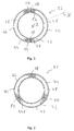
- FIG Fig. 2 An alternative embodiment of the support ring 36 is shown in FIG Fig. 2 shown.
- the support member body 40 is constructed with three body segments 72, 74, 76 and intermediate spaces 78, 80, 82 formed therebetween, respectively.
- the structural cohesion of the body segments 72, 74, 76 is provided by the support element 44 of the support arrangement 42, which preferably extends over the entire circumference in the U-profile interior 68.
- Each of the body segments 72, 74, 76 has a circumferential extent over an angular range of about 120 °, so that they can still be provided with higher manufacturing precision without the risk of warping when forming a sheet metal blank.
- all body segments are identical to each other, so that the number of different components to be provided for the production of such a support ring is small.
- a support ring With the embodiment of a support ring according to the invention, it is possible to provide a simple but nevertheless precise construction a means which can reliably support an exhaust treatment arrangement, for example a catalyst arrangement, in a tubular exhaust guide element of an exhaust system of an internal combustion engine and in particular also in the radially outer one Edge area can provide a protective effect against corrosion. Due to the flexibility provided by the construction according to the invention also in the circumferential and thus radial direction is further ensured that the support element itself is reliably supported in a tubular exhaust guide element, without the need for additional attachment measures are required.
- an exhaust treatment arrangement for example a catalyst arrangement
Landscapes
- Engineering & Computer Science (AREA)
- Chemical & Material Sciences (AREA)
- Chemical Kinetics & Catalysis (AREA)
- General Engineering & Computer Science (AREA)
- Mechanical Engineering (AREA)
- Combustion & Propulsion (AREA)
- Health & Medical Sciences (AREA)
- Toxicology (AREA)
- Exhaust Gas After Treatment (AREA)
Abstract
Description
- Die vorliegende Erfindung betrifft einen Stützring, welcher beispielsweise in einem Abgasführungssystem einer Brennkraftmaschine eines Fahrzeugs eingesetzt werden kann, um eine Abstützwirkung für eine im Abgasführungssystem vorgesehene Abgasbehandlungsanordnung, beispielsweise Katalysatoranordnung, zu erzeugen.
- In
Fig. 4 ist eine Abgasführungsbaugruppe 10 für ein Abgasführungssystem dargestellt vorgesehen. Diese Abgasführungsbaugruppe 10 umfasst ein rohrartiges Abgasführungselement 12. Das rohrartige Abgasführungselement 12 weist einen im Wesentlichen zylindrischen zentralen Abschnitt 14 und vorzugsweise an beiden Endbereichen jeweilige zylindrische Endabschnitte 16 bzw. 18 auf. Im Übergang vom zentralen Abschnitt 14 zu den Endabschnitten 16, 18 ist jeweils ein beispielsweise konusartiger Erweiterungsbereich 20 bzw. 22 vorgesehen. - In dem Abgasführungselement 12 ist eine allgemein mit 24 bezeichnete Abgasbehandlungsanordnung, beispielsweise Katalysatoranordnung, vorgesehen. Diese umfasst eine Katalysatoreinheit 26 beispielsweise mit einem Substrat und daran getragenem Katalysatormaterial. An ihrem Außenumfangsbereich ist die Katalysatoreinheit 26 umgeben von einer Lagermatte 28, also einem mattenartigen, flexiblen Material, welches auch durch Presswirkung die Katalysatoreinheit 26 im Wesentlichen im zentralen Abschnitt 14 festhält.
- In Zuordnung zu wenigstens einem der beiden in Richtung einer Längsachse A der Abgasführungsbaugruppe 10 gelegenen Endbereiche 30, 32 der Abgasbehandlungsanordnung 24 ist jeweils ein Stützring 36, 38 vorgesehen. Jeder Stützring 36, 38 stützt sich unter Presspassung nach radial außen hin am Innenumfang eines jeweiligen Endabschnitts 16, 18 des Abgasführungselements 12 ab und ist auf diese Art und Weise im Abgasführungselement 12 gehalten. Jeder Stützring 36, 38 überdeckt in axialer Richtung den radial äußeren Randbereich der Katalysatoreinheit 26. Auf diese Art und Weise ist zusätzlich zu der vorangehend bereits angesprochenen Presshalterung im zentralen Abschnitt 14 des Abgasführungselements 12 ein weiterer Beitrag für eine Abstützwirkung für die Katalysatoreinheit 26 bzw. allgemein die Abgasbehandlungsanordnung 24 vorgesehen. Weiter ist von Vorteil, dass durch das Überdecken des radial äußeren Randbereichs die Katalysatoreinheit 26 in diesem Bereich gegen Korrosion geschützt ist.
- Jeder Stützring 36, 38 ist mit einem beispielsweise als Blechumformteil ausgebildeten Stützelementenkörper 40 aufgebaut, der im Querschnitt mit einem U-Profil ausgebildet ist. In dem U-Profilinnenraum ist eine Stützanordnung 42 vorgesehen, welche beispielsweise ein aus Drahtgestrick aufgebautes Stützelement 44 umfassen kann. Dieses flexible Stützelement 44 stützt die Katalysatoreinheit 26 axial ab, ohne dessen strukturelle Integrität, insbesondere das Katalysatormaterial, zu verletzen.
- Es ist die Aufgabe der vorliegenden Erfindung, einen Stützring für ein Abgasführungssystem vorzusehen, welcher bei einfacher Herstellbarkeit eine zuverlässige Stützwirkung, beispielsweise für eine Abgasbehandlungsanordnung in einem Abgasführungssystem einer Brennkraftmaschine eines Fahrzeugs, erzeugen kann.
- Erfindungsgemäß wird diese Aufgabe gelöst durch einen Stützring für ein Abgasführungssystem, insbesondere einer Brennkraftmaschine eines Fahrzeugs, umfassend einen Stützelementenkörper mit einer Mehrzahl von Körpersegmenten und eine die Körpersegmente miteinander verbindende Stützanordnung.
- Da bei dem erfindungsgemäßen Stützring der Stützelementenkörper eine Mehrzahl von Körpersegmenten umfasst, also mit einer Mehrzahl von zusammen den Stützelementenkörper bereitstellenden Bauteilen aufgebaut ist, kann jedes dieser Körpersegmente in einfacher, gleichwohl jedoch präziser Art und Weise beispielsweise durch Umformen eines Blechrohlings generiert werden, so dass in seiner Gesamtheit der Stützelementenkörper beispielsweise mit kreisringartiger Struktur und einer Mehrzahl von in Umfangsrichtung aufeinander folgenden Körpersegmenten aufgebaut sein kann. Da keines der Körpersegmente sich über einen gesamten Umfangsbereich erstrecken muss, können diese auch bei der grundsätzlich gekrümmten Konfiguration mit hoher Fertigungspräzision bereitgestellt werden, so dass einerseits eine zuverlässige Stützwirkung nach radial außen erzeugt werden kann, um den Stützring in einem Abgasführungselement halten zu können, andererseits aber zuverlässig auch die Abstützwirkung für eine Abgasbehandlungsanordnung generiert werden kann.
- Um den strukturellen Zusammenhalt des Stützrings in einfacher Weise bereitstellen zu können, wird vorgeschlagen, dass wenigstens zwei Körpersegmente in einander gegenüberliegenden Körpersegmentendbereichen aneinander angrenzen, und dass die Stützanordnung die Körpersegmente miteinander verbindet. Bei dem erfindungsgemäßen Stützring erfüllt die Stützanordnung also nicht nur die Funktionalität zum Abstützen beispielsweise einer Abgasbehandlungsanordnung, sondern sorgt auch dafür, dass die grundsätzlich voneinander getrennt aufgebauten Körpersegmente miteinander verbunden werden.
- Um das Auftreten von Zwängungen beim Eingliedern eines erfindungsgemäßen Stützrings in ein beispielsweise rohrartiges Abgasführungselement vermeiden zu können, wird vorgeschlagen, dass zwischen den Körpersegmentendbereichen ein Zwischenraum gebildet ist.
- Vorteilhafterweise ist wenigstens ein, vorzugsweise jedes Körpersegment mit einem U-Profil ausgebildet, wobei die Stützanordnung wenigstens teilweise in einem UProfilinnenraum aufgenommen ist.
- Um die Stützwechselwirkung des Stützelements beispielsweise mit einer Abgasbehandlungsanordnung bereitstellen zu können bzw. nicht zu beeinträchtigen, wird weiter vorgeschlagen, dass das U-Profil einen radial inneren U-Schenkel, einen radial äußeren U-Schenkel und einen die U-schenkel verbindenden Verbindungsbereich aufweist, und dass ein U-Schenkel, vorzugsweise der radial innere U-Schenkel, kürzer ist, als der andere U-Schenkel. Vorteilhafterweise erstreckt sich dabei dann die Stützanordnung in Richtung vom Verbindungsbereich weg wenigstens über den kürzeren U-Schenkel hinaus.
- Zur Abstützwechselwirkung beispielsweise mit einer Abgasbehandlungsanordnung wird vorgeschlagen, dass die Stützanordnung flexibel ist. Vorteilhafterweise ist sie auch ringartig, vorzugsweise geschlossen ringartig ausgebildet, so dass über den gesamten Umfangsbereich einerseits die Stützwirkung erlangt werden kann, andererseits aber auch der Zusammenhalt der einzelnen Körpersegmente des Stützelementenkörpers erreicht wird.
- Um eine kostengünstige Herstellbarkeit zu gewährleisten, andererseits jedoch auch einen Aufbau zu erlangen, welcher für die vergleichsweise aggressive Umgebung in einem Abgasführungssystem geeignet ist, kann weiter vorgesehen sein, dass wenigstens ein Körpersegment, vorzugsweise jedes Körpersegment, als Blechumformteil ausgebildet ist.
- Um auch die Stützanordnung für die vergleichsweise aggressive Umgebung geeignet auszugestalten, wird vorgeschlagen, dass diese mit Drahtmaterial aufgebaut ist, vorzugsweise mit Drahtgestrick, Drahtgewirk, Drahtgeflecht oder Drahtgewebe, also allgemein einem Material, das z. B. aus einer Mehrzahl von Drahtfilamenten einen Volumenkörper bereitstellt.
- Um einen stabilen Zusammenhalt zu gewährleisten, wird vorgeschlagen, dass wenigstens ein Körpersegment, vorzugsweise jedes Körpersegment, mit der Stützanordnung fest verbunden ist, vorzugsweise durch Reibschluss oder/und Materialschluss.
- Die vorliegende Erfindung betrifft ferner eine Abgasführungsbaugruppe für ein Abgasführungssystem, insbesondere für eine Brennkraftmaschine eines Fahrzeugs, umfassend ein rohrartiges Abgasführungselement, eine in dem Abgasführungselement angeordnete Abgasbehandlungsanordnung, vorzugsweise Katalysatoranordnung, sowie an wenigstens einem Endbereich der Abgasbehandlungsanordnung einen Stützring mit dem vorangehend beschriebenen Aufbau.
- Die vorliegende Erfindung wird nachfolgend mit Bezug auf die beiliegenden Figuren detailliert beschrieben. Es zeigt:
- Fig. 1
- eine Draufsicht auf einen Stützring einer ersten Ausgestaltungsform;
- Fig. 2
- eine Draufsicht auf einen Stützring einer zweiten Ausgestaltungsform;
- Fig. 3
- eine Querschnittdarstellung des Stützrings der
Fig. 1 , geschnitten längs einer Radiallinie III-III inFig. 1 ; - Fig. 4
- eine Längsschnittansicht einer Abgasführungsbaugruppe für ein Abgasführungssystem.
- Eine Abgasführungsbaugruppe 10, bei welcher ein erfindungsgemäß aufgebauter Stützring zum Einsatz kommen kann, wurde vorangehend mit Bezug auf die
Fig. 4 beschrieben, so dass auf die diesbezüglichen Ausführungen verwiesen werden kann. Nachfolgend wird mit Bezug auf dieFig. 1 bis 3 der Aufbau eines Stützrings beschrieben, der beispielsweise als Stützring 36 oder als Stützring 38 bei dem inFig. 4 gezeigten Aufbau eingesetzt werden kann. Beispielhaft sei im Folgenden Bezug genommen auf den Stützring 36. - In
Fig. 1 ist ein Aufbau gezeigt, bei welchem der Stützring 36 einen Stützelementenkörper 40 mit zwei Körpersegmenten 46, 48 aufweist. Jedes der Körpersegmente 46, 48 ist kreisringsegmentartig ausgebildet und erstreckt sich nahezu über einen Winkelbereich von 180°. Die jeweiligen Körpersegmentendbereiche 50, 52, 54, 56 der beiden Körpersegmente 46, 48 liegen einander unter Beibehalt eines Zwischenraums 58, 60 mit Umfangsabstand gegenüber, grenzen also in diesen Bereichen aneinander an. - Wie die
Fig. 3 dies anhand des Körpersegments 48 beispielhaft zeigt, ist der Stützelementenkörper 40 bzw. sind die Körpersegmente 46, 48 im Querschnitt mit U-Profil ausgebildet. Sie umfassen einen bezüglich der Ringstruktur radial inneren USchenkel 62 und einen radial äußeren U-Schenkel 64. Diese beiden sich beispielsweise im Wesentlichen parallel zueinander erstreckenden U-Schenkel 62, 64 sind durch einen beispielsweise im Wesentlichen plan ausgebildeten Verbindungsbereich 66 miteinander verbunden. Jedes der Körpersegmente 46, 48 kann in einfacher Art und Weise als Blechumformteil bereitgestellt werden. Da keines der Körpersegmente 46, 48 sich im Wesentlichen über einen gesamten Umfangsbereich erstreckt, können diese Körpersegmente 46, 48 auch bei der vorangehend beschriebenen Herstellungsmethode im Wesentlichen verzugfrei bereitgestellt werden. - In einen jeweiligen U-Profilinnenraum 68 des Stützelementenkörpers 40 bzw. der Körpersegmente 46, 48 ist das vorangehend bereits angesprochene Stützelement 44 der Stützanordnung 42 eingesetzt. Das beispielsweise mit Drahtmaterial, beispielsweise Drahtgestrick oder dergleichen, aufgebaute Stützelement 44 erstreckt sich vorzugsweise im Wesentlichen ringartig und unterbrechungsfrei über den gesamten Umfang des Stützelementenkörpers 40 und überbrückt insbesondere die Zwischenräume 58, 60. Auf diese Art und Weise werden die beiden Körpersegmente 46, 48 zum Bereitstellen der ringartigen Struktur des Stützrings 36 zusammengehalten.
- Um einen stabilen Verbund des Stützelements 44 mit den Körpersegmenten 46, 48 zu erreichen, kann an vorzugsweise mehreren Umfangspositionen beispielsweise durch lokales Verpressen der Gestrickstruktur des Stützelements 44 dieses in den U-Profilinnenraum 68 so eingepresst werden, dass es unter Reibpressung an den U-Schenkeln 62, 64 anliegt und gegen Herausrutschen gehalten ist. Alternativ oder zusätzlich kann insbesondere an diesen Verpressungsbereichen ein Materialschluss durch Verschweißung 70 generiert werden. Hierzu sind insbesondere die vorangehend angesprochenen Verpressungsbereiche geeignet, da in diesen Bereichen die Gestrickstruktur des Stützelements 44 verdichtet ist und somit für einen Schweißvorgang bessere Konditionen für den Stromfluss geschaffen sind. Vorzugsweise sind bei jedem der beiden Körpersegmente 46, 48 wenigstens zwei derartige Anbindungsbereiche geschaffen.
- Man erkennt in
Fig. 3 deutlich, dass die beiden U-Schenkel 62, 64 ausgehend vom Verbindungsbereich 66 unterschiedliche Erstreckungslängen aufweisen. Der radial inneren der beiden U-Schenkel 62, 64 ist kürzer, als der radial äußere. Wie dies inFig. 4 zu erkennen ist, ist damit gewährleistet, dass der näherungsweise im radialen Mittenbereich des Stützelements 44 endende äußere Randbereich der Katalysator-einheit 26 sich axial am Stützelement 44 abstützen kann, dabei jedoch der radial innere U-Schenkel 62 noch axialen Abstand zur Katalysatoreinheit 26 aufweist, so dass die Abstützwechselwirkung nicht beeinträchtigt wird. - Eine alternative Ausgestaltungsform des Stützrings 36 ist in
Fig. 2 gezeigt. Hier ist der Stützelementenkörper 40 mit drei Körpersegmenten 72, 74, 76 und dazwischen jeweils gebildeten Zwischenräumen 78, 80, 82 aufgebaut. Auch hier wird der strukturelle Zusammenhalt der Körpersegmente 72, 74, 76 durch das im U-Profilinnenraum 68 sich vorzugsweise über den gesamten Umfang erstreckende Stützelement 44 der Stützanordnung 42 bereitgestellt. Jedes der Körpersegmente 72, 74, 76 weist eine Umfangserstreckung über einen Winkelbereich von etwa 120° auf, so dass diese noch mit höherer Fertigungspräzsion ohne der Gefahr des Verziehens beim Umformen eines Blechrohlings bereitgestellt werden können. Ebenso wie bei der vorangehend beschriebenen Ausgestaltungsform sind vorzugsweise alle Körpersegmente zueinander baugleich, so dass die Anzahl der verschiedenen zur Fertigung eines derartigen Stützrings bereitzuhaltenden Bauteile klein ist. - Mit der erfindungsgemäßen Ausgestaltung eines Stützrings wird es möglich, bei einfachem, gleichwohl jedoch präzise zu fertigendem Aufbau ein Mittel bereitzustellen, welches eine Abgasbehandlungsanordnung, beispielsweise eine Katalysatoranord-nung, zuverlässig in einem rohrartigen Abgasführungselement eines Abgasführungssystems einer Brennkraftmaschine haltern kann und insbesondere auch im radial äußeren Randbereich eine Schutzwirkung gegen Korrosion bereitstellen kann. Durch die aufgrund des erfindungsgemäßen Aufbaus vorgesehene Flexibilität auch in Umfangs- und somit Radialrichtung wird weiterhin dafür gesorgt, dass das Stützelement selbst zuverlässig in einem rohrartigen Abgasführungselement gehaltert wird, ohne dass hierfür zusätzliche Befestigungsmaßnahmen erforderlich sind.
Claims (10)
- Stützring für ein Abgasführungssystem, insbesondere einer Brennkraftmaschine eines Fahrzeugs, umfassend einen Stützelementenkörper (40) mit einer Mehrzahl von Körpersegmenten (46, 48; 72, 74, 76) und eine die Körpersegmente (46, 48; 72, 74, 76) miteinander verbindende Stützanordnung (42).
- Stützring nach Anspruch 1, dadurch gekennzeichnet, dass wenigstens zwei Körpersegmente (46, 48; 72, 74, 76) in einander gegenüberliegenden Körpersegmentendbereichen (50, 52, 54, 56) aneinander angrenzen, und dass die Stützanordnung (42) die Körpersegmente (46, 48; 72, 74, 76) miteinander verbindet.
- Stützring nach Anspruch 2, dadurch gekennzeichnet, dass zwischen den Körpersegmentendbereichen ein Zwischenraum (58, 60; 78, 80, 82) gebildet ist.
- Stützring nach einem der Ansprüche 1-3, dadurch gekennzeichnet, dass wenigstens ein, vorzugsweise alle Körpersegmente (46, 48; 72, 74, 76) mit U-Profil ausgebildet sind, und dass die Stützanordnung (42) wenigstens teilweise in einem U-Profilinnenraum (68) aufgenommen ist.
- Stützring nach Anspruch 4, dadurch gekennzeichnet, dass das U-Profil einen radial inneren U-Schenkel (62), einen radial äußeren U-Schenkel (64) und einen die U-Schenkel (62, 64) verbindenden Verbindungsbereich (66) aufweist, und dass ein U-Schenkel (62), vorzugsweise der radial innere U-Schenkel (62), kürzer ist, als der andere U-Schenkel (64).
- Stützring nach Anspruch 5, dadurch gekennzeichnet, dass die Stützanordnung (42) sich in Richtung vom Verbindungsbereich (66) weg wenigstens über den kürzeren U-Schenkel (62) hinaus erstreckt.
- Stützring nach einem der Ansprüche 1-6, dadurch gekennzeichnet, dass die Stützanordnung (42) flexibel ist, oder/und dass die Stützanordnung (42) ringartig, vorzugsweise geschlossen ringartig, ausgebildet ist, oder/und dass wenigstens ein Körpersegment (46, 48; 72, 74, 76), vorzugsweise jedes Körpersegment (46, 48; 72, 74, 76), als Blechumformteil ausgebildet ist.
- Stützring nach Anspruch 7, dadurch gekennzeichnet, dass die Stützanordnung (42) mit Metalldrahtmaterial, vorzugsweise Drahtgestrick, Drahtgewirk, Drahtgeflecht oder Drahtgewebe, aufgebaut ist.
- Stützring nach einem der Ansprüche 1-8, dadurch gekennzeichnet, dass wenigstens ein Körpersegment (46, 48; 72, 74, 76), vorzugsweise jedes Körpersegment (46, 48; 72, 74, 76), mit der Stützanordnung (42) fest verbunden ist, vorzugsweise durch Reibschluss oder/und Materialschluss.
- Abgasführungsbaugruppe für ein Abgasführungssystem, insbesondere für eine Brennkraftmaschine eines Fahrzeugs, umfassend ein rohrartiges Abgasführungselement (12), eine in dem Abgasführungselement (12) angeordnete Abgasbehandlungsanordnung (24), vorzugsweise Katalysatoranordnung, sowie an wenigstens einem Endbereich (30, 32) der Abgasbehandlungsanordnung (24) einen Stützring (36, 38) nach einem der vorangehenden Ansprüche.
Applications Claiming Priority (1)
| Application Number | Priority Date | Filing Date | Title |
|---|---|---|---|
| DE102015100552.2A DE102015100552B3 (de) | 2015-01-15 | 2015-01-15 | Stützring für ein Abgasführungssystem |
Publications (2)
| Publication Number | Publication Date |
|---|---|
| EP3045694A1 true EP3045694A1 (de) | 2016-07-20 |
| EP3045694B1 EP3045694B1 (de) | 2017-12-20 |
Family
ID=55077438
Family Applications (1)
| Application Number | Title | Priority Date | Filing Date |
|---|---|---|---|
| EP16150593.8A Active EP3045694B1 (de) | 2015-01-15 | 2016-01-08 | Stützring für ein abgasführungssystem |
Country Status (5)
| Country | Link |
|---|---|
| US (1) | US9765680B2 (de) |
| EP (1) | EP3045694B1 (de) |
| JP (1) | JP2016133120A (de) |
| CN (1) | CN105804839B (de) |
| DE (1) | DE102015100552B3 (de) |
Families Citing this family (5)
| Publication number | Priority date | Publication date | Assignee | Title |
|---|---|---|---|---|
| DE102016121721A1 (de) | 2016-11-14 | 2018-05-17 | Eberspächer Exhaust Technology GmbH & Co. KG | Verfahren zur Herstellung eines Klappenträgers für eine Abgasklappe |
| CN108868970A (zh) * | 2018-06-14 | 2018-11-23 | 山东沃蓝环保设备有限公司 | 一种利用插装式连接方法的尾气处理装置 |
| CN108533368A (zh) * | 2018-06-14 | 2018-09-14 | 山东沃蓝环保设备有限公司 | 一种安装加热装置的尾气净化装置 |
| DE102019121411A1 (de) * | 2019-08-08 | 2021-02-11 | Eberspächer Exhaust Technology GmbH & Co. KG | Abgasbehandlungsbaugruppe |
| EP4047192B1 (de) | 2021-02-18 | 2023-11-22 | Purem GmbH | Abstützbaugruppe zur abstützung eines in einem gehäuse aufgenommenen abgasbehandlungselements |
Citations (2)
| Publication number | Priority date | Publication date | Assignee | Title |
|---|---|---|---|---|
| JP2000018029A (ja) * | 1998-06-30 | 2000-01-18 | Calsonic Corp | マニホールドコンバータ |
| WO2011066041A1 (en) * | 2009-11-30 | 2011-06-03 | Acs Industries, Inc. | Mounting assemblies for substrates |
Family Cites Families (14)
| Publication number | Priority date | Publication date | Assignee | Title |
|---|---|---|---|---|
| JPS53148881A (en) * | 1977-05-31 | 1978-12-25 | Matsushita Electric Works Ltd | Shutter for illuminator |
| US4393559A (en) * | 1981-07-14 | 1983-07-19 | Heckethorn Manufacturing Company | U-Bolt clamp with tubular reinforcing means |
| US4643458A (en) * | 1984-04-06 | 1987-02-17 | Ammar Jesse I | Support and clamping assembly |
| JPS644096Y2 (de) * | 1985-10-31 | 1989-02-02 | ||
| US20050002836A1 (en) * | 2001-04-13 | 2005-01-06 | Hardesty Jeffrey B. | Gas treatment device, and methods of making and using the same |
| DE10300780A1 (de) * | 2003-01-11 | 2004-07-22 | J. Eberspächer GmbH & Co. KG | Abgasbehandlungseinrichtung |
| DE102004051512B4 (de) * | 2004-10-21 | 2007-02-08 | J. Eberspächer GmbH & Co. KG | Partikelfilter für eine Abgasanlage |
| US7501005B2 (en) * | 2005-02-28 | 2009-03-10 | Caterpillar Inc. | Exhaust treatment device having submerged connecting flanges |
| JP5173180B2 (ja) * | 2006-10-30 | 2013-03-27 | 株式会社キャタラー | 排ガス浄化用触媒 |
| JP2009150242A (ja) * | 2007-12-19 | 2009-07-09 | Nippon Reinz Co Ltd | セラミック製ハニカム用緩衝部材及びその製造方法 |
| JP4834041B2 (ja) * | 2008-08-04 | 2011-12-07 | 本田技研工業株式会社 | 排ガス浄化装置 |
| JP2010190124A (ja) * | 2009-02-18 | 2010-09-02 | Toyota Industries Corp | 排ガス浄化装置 |
| DE102009014435A1 (de) * | 2009-03-26 | 2010-10-14 | J. Eberspächer GmbH & Co. KG | Abgasbehandlungseinrichtung |
| US8136770B2 (en) * | 2009-08-24 | 2012-03-20 | International Engine Intellectual Property Company, Llc | Mount for exhaust system components |
-
2015
- 2015-01-15 DE DE102015100552.2A patent/DE102015100552B3/de active Active
-
2016
- 2016-01-08 EP EP16150593.8A patent/EP3045694B1/de active Active
- 2016-01-13 US US14/994,553 patent/US9765680B2/en not_active Expired - Fee Related
- 2016-01-14 CN CN201610021501.7A patent/CN105804839B/zh active Active
- 2016-01-15 JP JP2016006154A patent/JP2016133120A/ja active Pending
Patent Citations (2)
| Publication number | Priority date | Publication date | Assignee | Title |
|---|---|---|---|---|
| JP2000018029A (ja) * | 1998-06-30 | 2000-01-18 | Calsonic Corp | マニホールドコンバータ |
| WO2011066041A1 (en) * | 2009-11-30 | 2011-06-03 | Acs Industries, Inc. | Mounting assemblies for substrates |
Also Published As
| Publication number | Publication date |
|---|---|
| CN105804839B (zh) | 2018-11-06 |
| JP2016133120A (ja) | 2016-07-25 |
| EP3045694B1 (de) | 2017-12-20 |
| US9765680B2 (en) | 2017-09-19 |
| US20160208673A1 (en) | 2016-07-21 |
| DE102015100552B3 (de) | 2016-06-16 |
| CN105804839A (zh) | 2016-07-27 |
Similar Documents
| Publication | Publication Date | Title |
|---|---|---|
| EP3045694B1 (de) | Stützring für ein abgasführungssystem | |
| EP0212331B1 (de) | Verbindung zweier Rohre einer Leitung für heisse Medien | |
| EP2627919B1 (de) | Axiallageranordnung | |
| DE112008004188T5 (de) | Grommet | |
| EP2831441B1 (de) | Nehmerzylinder | |
| EP2980427A1 (de) | Gleitlagervorrichtung | |
| DE202007013516U1 (de) | Dämpfungsanordnung | |
| DE102010022708A1 (de) | Ventiltrieb einer Brennkraftmaschine sowie entsprechende Brennkraftmaschine | |
| DE102014012169A1 (de) | Entkopplungselement | |
| EP2913495B1 (de) | Verfahren zum Herstellen einer Abgasnachbehandlungseinrichtung und entsprechende Abgasnachbehandlungseinrichtung | |
| EP3199772A1 (de) | Schalldämpfer für eine abgasanlage | |
| EP1241389B1 (de) | Leitungselement mit einem Balg aus Metall | |
| DE102011008927A1 (de) | Gleitringdichtungsanordnung mit Federringscheibe | |
| DE102012216097B4 (de) | Entkoppelelement | |
| WO2019038182A1 (de) | Hitzeschild mit dichtelement | |
| DE102022111864A1 (de) | Heizvorrichtung | |
| EP3907383A1 (de) | Abgasheizer für eine abgasanlage einer brennkraftmaschine | |
| DE102021205783A1 (de) | Wellenfeder | |
| DE102015111324A1 (de) | Ventilvorrichtung für eine Verbrennungskraftmaschine | |
| EP2554455B1 (de) | Lenksäule mit Lenkungslager und Lenkungslager einer Lenksäule | |
| WO1999025984A1 (de) | Schrägkugellager | |
| DE102019213718A1 (de) | Hitzeschild und Bauelement mit einem derartigen Hitzeschild | |
| EP3401584B1 (de) | Rohr, insbesondere abgasführungsrohr | |
| DE102016217851A1 (de) | Doppelkupplung für ein Kraftfahrzeug | |
| DE102021125803A1 (de) | Axiallager sowie Axiallageranordnung umfassend zwei solche Axiallager |
Legal Events
| Date | Code | Title | Description |
|---|---|---|---|
| PUAI | Public reference made under article 153(3) epc to a published international application that has entered the european phase |
Free format text: ORIGINAL CODE: 0009012 |
|
| 17P | Request for examination filed |
Effective date: 20160108 |
|
| AK | Designated contracting states |
Kind code of ref document: A1 Designated state(s): AL AT BE BG CH CY CZ DE DK EE ES FI FR GB GR HR HU IE IS IT LI LT LU LV MC MK MT NL NO PL PT RO RS SE SI SK SM TR |
|
| AX | Request for extension of the european patent |
Extension state: BA ME |
|
| 17Q | First examination report despatched |
Effective date: 20170209 |
|
| RIC1 | Information provided on ipc code assigned before grant |
Ipc: F01N 3/28 20060101AFI20170706BHEP Ipc: F01N 13/08 20100101ALI20170706BHEP Ipc: F01N 3/021 20060101ALI20170706BHEP Ipc: F01N 3/20 20060101ALI20170706BHEP Ipc: F01N 13/18 20100101ALI20170706BHEP Ipc: F16L 3/10 20060101ALI20170706BHEP |
|
| GRAP | Despatch of communication of intention to grant a patent |
Free format text: ORIGINAL CODE: EPIDOSNIGR1 |
|
| INTG | Intention to grant announced |
Effective date: 20170818 |
|
| GRAS | Grant fee paid |
Free format text: ORIGINAL CODE: EPIDOSNIGR3 |
|
| GRAA | (expected) grant |
Free format text: ORIGINAL CODE: 0009210 |
|
| AK | Designated contracting states |
Kind code of ref document: B1 Designated state(s): AL AT BE BG CH CY CZ DE DK EE ES FI FR GB GR HR HU IE IS IT LI LT LU LV MC MK MT NL NO PL PT RO RS SE SI SK SM TR |
|
| REG | Reference to a national code |
Ref country code: GB Ref legal event code: FG4D Free format text: NOT ENGLISH |
|
| REG | Reference to a national code |
Ref country code: CH Ref legal event code: EP |
|
| REG | Reference to a national code |
Ref country code: IE Ref legal event code: FG4D Free format text: LANGUAGE OF EP DOCUMENT: GERMAN |
|
| REG | Reference to a national code |
Ref country code: AT Ref legal event code: REF Ref document number: 956598 Country of ref document: AT Kind code of ref document: T Effective date: 20180115 |
|
| REG | Reference to a national code |
Ref country code: DE Ref legal event code: R096 Ref document number: 502016000357 Country of ref document: DE |
|
| REG | Reference to a national code |
Ref country code: FR Ref legal event code: PLFP Year of fee payment: 3 |
|
| REG | Reference to a national code |
Ref country code: SE Ref legal event code: TRGR |
|
| REG | Reference to a national code |
Ref country code: NL Ref legal event code: MP Effective date: 20171220 |
|
| PG25 | Lapsed in a contracting state [announced via postgrant information from national office to epo] |
Ref country code: NO Free format text: LAPSE BECAUSE OF FAILURE TO SUBMIT A TRANSLATION OF THE DESCRIPTION OR TO PAY THE FEE WITHIN THE PRESCRIBED TIME-LIMIT Effective date: 20180320 Ref country code: LT Free format text: LAPSE BECAUSE OF FAILURE TO SUBMIT A TRANSLATION OF THE DESCRIPTION OR TO PAY THE FEE WITHIN THE PRESCRIBED TIME-LIMIT Effective date: 20171220 Ref country code: FI Free format text: LAPSE BECAUSE OF FAILURE TO SUBMIT A TRANSLATION OF THE DESCRIPTION OR TO PAY THE FEE WITHIN THE PRESCRIBED TIME-LIMIT Effective date: 20171220 |
|
| REG | Reference to a national code |
Ref country code: LT Ref legal event code: MG4D |
|
| PG25 | Lapsed in a contracting state [announced via postgrant information from national office to epo] |
Ref country code: RS Free format text: LAPSE BECAUSE OF FAILURE TO SUBMIT A TRANSLATION OF THE DESCRIPTION OR TO PAY THE FEE WITHIN THE PRESCRIBED TIME-LIMIT Effective date: 20171220 Ref country code: LV Free format text: LAPSE BECAUSE OF FAILURE TO SUBMIT A TRANSLATION OF THE DESCRIPTION OR TO PAY THE FEE WITHIN THE PRESCRIBED TIME-LIMIT Effective date: 20171220 Ref country code: BG Free format text: LAPSE BECAUSE OF FAILURE TO SUBMIT A TRANSLATION OF THE DESCRIPTION OR TO PAY THE FEE WITHIN THE PRESCRIBED TIME-LIMIT Effective date: 20180320 Ref country code: GR Free format text: LAPSE BECAUSE OF FAILURE TO SUBMIT A TRANSLATION OF THE DESCRIPTION OR TO PAY THE FEE WITHIN THE PRESCRIBED TIME-LIMIT Effective date: 20180321 Ref country code: HR Free format text: LAPSE BECAUSE OF FAILURE TO SUBMIT A TRANSLATION OF THE DESCRIPTION OR TO PAY THE FEE WITHIN THE PRESCRIBED TIME-LIMIT Effective date: 20171220 |
|
| PG25 | Lapsed in a contracting state [announced via postgrant information from national office to epo] |
Ref country code: NL Free format text: LAPSE BECAUSE OF FAILURE TO SUBMIT A TRANSLATION OF THE DESCRIPTION OR TO PAY THE FEE WITHIN THE PRESCRIBED TIME-LIMIT Effective date: 20171220 |
|
| REG | Reference to a national code |
Ref country code: DE Ref legal event code: R082 Ref document number: 502016000357 Country of ref document: DE Representative=s name: RUTTENSPERGER LACHNIT TROSSIN GOMOLL, PATENT- , DE Ref country code: DE Ref legal event code: R082 Ref document number: 502016000357 Country of ref document: DE Representative=s name: RUTTENSPERGER LACHNIT TROSSIN GOMOLL PATENT- U, DE |
|
| PG25 | Lapsed in a contracting state [announced via postgrant information from national office to epo] |
Ref country code: CY Free format text: LAPSE BECAUSE OF FAILURE TO SUBMIT A TRANSLATION OF THE DESCRIPTION OR TO PAY THE FEE WITHIN THE PRESCRIBED TIME-LIMIT Effective date: 20171220 Ref country code: EE Free format text: LAPSE BECAUSE OF FAILURE TO SUBMIT A TRANSLATION OF THE DESCRIPTION OR TO PAY THE FEE WITHIN THE PRESCRIBED TIME-LIMIT Effective date: 20171220 Ref country code: SK Free format text: LAPSE BECAUSE OF FAILURE TO SUBMIT A TRANSLATION OF THE DESCRIPTION OR TO PAY THE FEE WITHIN THE PRESCRIBED TIME-LIMIT Effective date: 20171220 Ref country code: ES Free format text: LAPSE BECAUSE OF FAILURE TO SUBMIT A TRANSLATION OF THE DESCRIPTION OR TO PAY THE FEE WITHIN THE PRESCRIBED TIME-LIMIT Effective date: 20171220 Ref country code: CZ Free format text: LAPSE BECAUSE OF FAILURE TO SUBMIT A TRANSLATION OF THE DESCRIPTION OR TO PAY THE FEE WITHIN THE PRESCRIBED TIME-LIMIT Effective date: 20171220 |
|
| PG25 | Lapsed in a contracting state [announced via postgrant information from national office to epo] |
Ref country code: RO Free format text: LAPSE BECAUSE OF FAILURE TO SUBMIT A TRANSLATION OF THE DESCRIPTION OR TO PAY THE FEE WITHIN THE PRESCRIBED TIME-LIMIT Effective date: 20171220 Ref country code: IS Free format text: LAPSE BECAUSE OF FAILURE TO SUBMIT A TRANSLATION OF THE DESCRIPTION OR TO PAY THE FEE WITHIN THE PRESCRIBED TIME-LIMIT Effective date: 20180420 Ref country code: PL Free format text: LAPSE BECAUSE OF FAILURE TO SUBMIT A TRANSLATION OF THE DESCRIPTION OR TO PAY THE FEE WITHIN THE PRESCRIBED TIME-LIMIT Effective date: 20171220 Ref country code: SM Free format text: LAPSE BECAUSE OF FAILURE TO SUBMIT A TRANSLATION OF THE DESCRIPTION OR TO PAY THE FEE WITHIN THE PRESCRIBED TIME-LIMIT Effective date: 20171220 |
|
| REG | Reference to a national code |
Ref country code: DE Ref legal event code: R097 Ref document number: 502016000357 Country of ref document: DE |
|
| PG25 | Lapsed in a contracting state [announced via postgrant information from national office to epo] |
Ref country code: MT Free format text: LAPSE BECAUSE OF FAILURE TO SUBMIT A TRANSLATION OF THE DESCRIPTION OR TO PAY THE FEE WITHIN THE PRESCRIBED TIME-LIMIT Effective date: 20171220 Ref country code: MC Free format text: LAPSE BECAUSE OF FAILURE TO SUBMIT A TRANSLATION OF THE DESCRIPTION OR TO PAY THE FEE WITHIN THE PRESCRIBED TIME-LIMIT Effective date: 20171220 |
|
| PG25 | Lapsed in a contracting state [announced via postgrant information from national office to epo] |
Ref country code: LU Free format text: LAPSE BECAUSE OF NON-PAYMENT OF DUE FEES Effective date: 20180108 |
|
| REG | Reference to a national code |
Ref country code: IE Ref legal event code: MM4A |
|
| PLBE | No opposition filed within time limit |
Free format text: ORIGINAL CODE: 0009261 |
|
| STAA | Information on the status of an ep patent application or granted ep patent |
Free format text: STATUS: NO OPPOSITION FILED WITHIN TIME LIMIT |
|
| REG | Reference to a national code |
Ref country code: BE Ref legal event code: MM Effective date: 20180131 |
|
| PG25 | Lapsed in a contracting state [announced via postgrant information from national office to epo] |
Ref country code: DK Free format text: LAPSE BECAUSE OF FAILURE TO SUBMIT A TRANSLATION OF THE DESCRIPTION OR TO PAY THE FEE WITHIN THE PRESCRIBED TIME-LIMIT Effective date: 20171220 Ref country code: BE Free format text: LAPSE BECAUSE OF NON-PAYMENT OF DUE FEES Effective date: 20180131 |
|
| 26N | No opposition filed |
Effective date: 20180921 |
|
| PG25 | Lapsed in a contracting state [announced via postgrant information from national office to epo] |
Ref country code: IE Free format text: LAPSE BECAUSE OF NON-PAYMENT OF DUE FEES Effective date: 20180108 |
|
| PG25 | Lapsed in a contracting state [announced via postgrant information from national office to epo] |
Ref country code: SI Free format text: LAPSE BECAUSE OF FAILURE TO SUBMIT A TRANSLATION OF THE DESCRIPTION OR TO PAY THE FEE WITHIN THE PRESCRIBED TIME-LIMIT Effective date: 20171220 |
|
| PGFP | Annual fee paid to national office [announced via postgrant information from national office to epo] |
Ref country code: FR Payment date: 20190326 Year of fee payment: 12 |
|
| REG | Reference to a national code |
Ref country code: CH Ref legal event code: PL |
|
| PG25 | Lapsed in a contracting state [announced via postgrant information from national office to epo] |
Ref country code: CH Free format text: LAPSE BECAUSE OF NON-PAYMENT OF DUE FEES Effective date: 20190131 Ref country code: LI Free format text: LAPSE BECAUSE OF NON-PAYMENT OF DUE FEES Effective date: 20190131 |
|
| PG25 | Lapsed in a contracting state [announced via postgrant information from national office to epo] |
Ref country code: TR Free format text: LAPSE BECAUSE OF FAILURE TO SUBMIT A TRANSLATION OF THE DESCRIPTION OR TO PAY THE FEE WITHIN THE PRESCRIBED TIME-LIMIT Effective date: 20171220 |
|
| PG25 | Lapsed in a contracting state [announced via postgrant information from national office to epo] |
Ref country code: PT Free format text: LAPSE BECAUSE OF FAILURE TO SUBMIT A TRANSLATION OF THE DESCRIPTION OR TO PAY THE FEE WITHIN THE PRESCRIBED TIME-LIMIT Effective date: 20171220 |
|
| PG25 | Lapsed in a contracting state [announced via postgrant information from national office to epo] |
Ref country code: HU Free format text: LAPSE BECAUSE OF FAILURE TO SUBMIT A TRANSLATION OF THE DESCRIPTION OR TO PAY THE FEE WITHIN THE PRESCRIBED TIME-LIMIT; INVALID AB INITIO Effective date: 20160108 Ref country code: MK Free format text: LAPSE BECAUSE OF NON-PAYMENT OF DUE FEES Effective date: 20171220 |
|
| PG25 | Lapsed in a contracting state [announced via postgrant information from national office to epo] |
Ref country code: AL Free format text: LAPSE BECAUSE OF FAILURE TO SUBMIT A TRANSLATION OF THE DESCRIPTION OR TO PAY THE FEE WITHIN THE PRESCRIBED TIME-LIMIT Effective date: 20171220 |
|
| PG25 | Lapsed in a contracting state [announced via postgrant information from national office to epo] |
Ref country code: IT Free format text: LAPSE BECAUSE OF NON-PAYMENT OF DUE FEES Effective date: 20200108 |
|
| REG | Reference to a national code |
Ref country code: DE Ref legal event code: R082 Ref document number: 502016000357 Country of ref document: DE Representative=s name: RUTTENSPERGER LACHNIT TROSSIN GOMOLL, PATENT- , DE Ref country code: DE Ref legal event code: R081 Ref document number: 502016000357 Country of ref document: DE Owner name: PUREM GMBH, DE Free format text: FORMER OWNER: EBERSPAECHER EXHAUST TECHNOLOGY GMBH & CO. KG, 66539 NEUNKIRCHEN, DE |
|
| REG | Reference to a national code |
Ref country code: GB Ref legal event code: 732E Free format text: REGISTERED BETWEEN 20210902 AND 20210908 |
|
| REG | Reference to a national code |
Ref country code: AT Ref legal event code: MM01 Ref document number: 956598 Country of ref document: AT Kind code of ref document: T Effective date: 20210108 |
|
| PG25 | Lapsed in a contracting state [announced via postgrant information from national office to epo] |
Ref country code: AT Free format text: LAPSE BECAUSE OF NON-PAYMENT OF DUE FEES Effective date: 20210108 |
|
| PGFP | Annual fee paid to national office [announced via postgrant information from national office to epo] |
Ref country code: DE Payment date: 20250120 Year of fee payment: 10 |
|
| PGFP | Annual fee paid to national office [announced via postgrant information from national office to epo] |
Ref country code: SE Payment date: 20250122 Year of fee payment: 10 |
|
| PGFP | Annual fee paid to national office [announced via postgrant information from national office to epo] |
Ref country code: GB Payment date: 20250123 Year of fee payment: 10 |