EP3045353B1 - Bildanzeigespiegel für ein fahrzeug - Google Patents
Bildanzeigespiegel für ein fahrzeug Download PDFInfo
- Publication number
- EP3045353B1 EP3045353B1 EP16151040.9A EP16151040A EP3045353B1 EP 3045353 B1 EP3045353 B1 EP 3045353B1 EP 16151040 A EP16151040 A EP 16151040A EP 3045353 B1 EP3045353 B1 EP 3045353B1
- Authority
- EP
- European Patent Office
- Prior art keywords
- image display
- polarizing plate
- display apparatus
- mirror
- half mirror
- Prior art date
- Legal status (The legal status is an assumption and is not a legal conclusion. Google has not performed a legal analysis and makes no representation as to the accuracy of the status listed.)
- Active
Links
Images

Classifications
-
- G—PHYSICS
- G09—EDUCATION; CRYPTOGRAPHY; DISPLAY; ADVERTISING; SEALS
- G09F—DISPLAYING; ADVERTISING; SIGNS; LABELS OR NAME-PLATES; SEALS
- G09F9/00—Indicating arrangements for variable information in which the information is built-up on a support by selection or combination of individual elements
- G09F9/30—Indicating arrangements for variable information in which the information is built-up on a support by selection or combination of individual elements in which the desired character or characters are formed by combining individual elements
- G09F9/35—Indicating arrangements for variable information in which the information is built-up on a support by selection or combination of individual elements in which the desired character or characters are formed by combining individual elements being liquid crystals
-
- B—PERFORMING OPERATIONS; TRANSPORTING
- B60—VEHICLES IN GENERAL
- B60R—VEHICLES, VEHICLE FITTINGS, OR VEHICLE PARTS, NOT OTHERWISE PROVIDED FOR
- B60R1/00—Optical viewing arrangements; Real-time viewing arrangements for drivers or passengers using optical image capturing systems, e.g. cameras or video systems specially adapted for use in or on vehicles
- B60R1/02—Rear-view mirror arrangements
-
- B—PERFORMING OPERATIONS; TRANSPORTING
- B60—VEHICLES IN GENERAL
- B60R—VEHICLES, VEHICLE FITTINGS, OR VEHICLE PARTS, NOT OTHERWISE PROVIDED FOR
- B60R1/00—Optical viewing arrangements; Real-time viewing arrangements for drivers or passengers using optical image capturing systems, e.g. cameras or video systems specially adapted for use in or on vehicles
- B60R1/02—Rear-view mirror arrangements
- B60R1/08—Rear-view mirror arrangements involving special optical features, e.g. avoiding blind spots, e.g. convex mirrors; Side-by-side associations of rear-view and other mirrors
- B60R1/083—Anti-glare mirrors, e.g. "day-night" mirrors
-
- B—PERFORMING OPERATIONS; TRANSPORTING
- B60—VEHICLES IN GENERAL
- B60R—VEHICLES, VEHICLE FITTINGS, OR VEHICLE PARTS, NOT OTHERWISE PROVIDED FOR
- B60R1/00—Optical viewing arrangements; Real-time viewing arrangements for drivers or passengers using optical image capturing systems, e.g. cameras or video systems specially adapted for use in or on vehicles
- B60R1/02—Rear-view mirror arrangements
- B60R1/08—Rear-view mirror arrangements involving special optical features, e.g. avoiding blind spots, e.g. convex mirrors; Side-by-side associations of rear-view and other mirrors
- B60R1/083—Anti-glare mirrors, e.g. "day-night" mirrors
- B60R1/084—Anti-glare mirrors, e.g. "day-night" mirrors using a removable filtering or hiding screen
-
- B—PERFORMING OPERATIONS; TRANSPORTING
- B60—VEHICLES IN GENERAL
- B60R—VEHICLES, VEHICLE FITTINGS, OR VEHICLE PARTS, NOT OTHERWISE PROVIDED FOR
- B60R1/00—Optical viewing arrangements; Real-time viewing arrangements for drivers or passengers using optical image capturing systems, e.g. cameras or video systems specially adapted for use in or on vehicles
- B60R1/02—Rear-view mirror arrangements
- B60R1/08—Rear-view mirror arrangements involving special optical features, e.g. avoiding blind spots, e.g. convex mirrors; Side-by-side associations of rear-view and other mirrors
- B60R1/083—Anti-glare mirrors, e.g. "day-night" mirrors
- B60R1/088—Anti-glare mirrors, e.g. "day-night" mirrors using a cell of electrically changeable optical characteristic, e.g. liquid-crystal or electrochromic mirrors
-
- B—PERFORMING OPERATIONS; TRANSPORTING
- B60—VEHICLES IN GENERAL
- B60R—VEHICLES, VEHICLE FITTINGS, OR VEHICLE PARTS, NOT OTHERWISE PROVIDED FOR
- B60R1/00—Optical viewing arrangements; Real-time viewing arrangements for drivers or passengers using optical image capturing systems, e.g. cameras or video systems specially adapted for use in or on vehicles
- B60R1/12—Mirror assemblies combined with other articles, e.g. clocks
-
- G—PHYSICS
- G02—OPTICS
- G02B—OPTICAL ELEMENTS, SYSTEMS OR APPARATUS
- G02B27/00—Optical systems or apparatus not provided for by any of the groups G02B1/00 - G02B26/00, G02B30/00
- G02B27/10—Beam splitting or combining systems
- G02B27/14—Beam splitting or combining systems operating by reflection only
- G02B27/144—Beam splitting or combining systems operating by reflection only using partially transparent surfaces without spectral selectivity
-
- G—PHYSICS
- G02—OPTICS
- G02B—OPTICAL ELEMENTS, SYSTEMS OR APPARATUS
- G02B27/00—Optical systems or apparatus not provided for by any of the groups G02B1/00 - G02B26/00, G02B30/00
- G02B27/28—Optical systems or apparatus not provided for by any of the groups G02B1/00 - G02B26/00, G02B30/00 for polarising
- G02B27/281—Optical systems or apparatus not provided for by any of the groups G02B1/00 - G02B26/00, G02B30/00 for polarising used for attenuating light intensity, e.g. comprising rotatable polarising elements
-
- G—PHYSICS
- G02—OPTICS
- G02B—OPTICAL ELEMENTS, SYSTEMS OR APPARATUS
- G02B5/00—Optical elements other than lenses
- G02B5/30—Polarising elements
- G02B5/3083—Birefringent or phase retarding elements
-
- B—PERFORMING OPERATIONS; TRANSPORTING
- B60—VEHICLES IN GENERAL
- B60R—VEHICLES, VEHICLE FITTINGS, OR VEHICLE PARTS, NOT OTHERWISE PROVIDED FOR
- B60R1/00—Optical viewing arrangements; Real-time viewing arrangements for drivers or passengers using optical image capturing systems, e.g. cameras or video systems specially adapted for use in or on vehicles
- B60R1/12—Mirror assemblies combined with other articles, e.g. clocks
- B60R2001/1215—Mirror assemblies combined with other articles, e.g. clocks with information displays
-
- G—PHYSICS
- G02—OPTICS
- G02B—OPTICAL ELEMENTS, SYSTEMS OR APPARATUS
- G02B5/00—Optical elements other than lenses
- G02B5/08—Mirrors
-
- G—PHYSICS
- G02—OPTICS
- G02B—OPTICAL ELEMENTS, SYSTEMS OR APPARATUS
- G02B5/00—Optical elements other than lenses
- G02B5/30—Polarising elements
Definitions
- the present invention relates to an image display mirror for a vehicle.
- Japanese Patent No. 5273286 discloses an image display mirror including a half mirror arranged on the front surface (viewer side surface) of a monitor.
- the rear can be viewed with a reflected image provided by the half mirror. Meanwhile, when an image is displayed on the monitor, the image can be viewed through the half mirror.
- Such image display mirror involves a problem in that, for example, when the quantity of light from the rear of a vehicle is large, the reflected image inhibits the visibility of the image displayed on the monitor.
- Japanese Patent No. 5273286 proposes the following technology. An influence of the reflected image is reduced by making the angle of the half mirror when a viewer (occupant) views the rear and the angle when the viewer views the image of the monitor different from each other. According to such technology, the influence of the reflected image provided by the half mirror can be reduced by adjusting the angle of the half mirror so that when the monitor image is viewed, the reflected image becomes an image that does not inhibit the visibility of the monitor image, specifically so that a ceiling is mirrored by reflection.
- a liquid crystal switchable image display mirror for a vehicle comprising a first and a second plarizer is disclosed in US-A1-2010/0277786 .
- the present invention has been made to solve the conventional problems, and an object of the present invention is to provide an image display mirror that includes a half mirror and an image display apparatus, reduces an influence of a reflected image provided by the half mirror, and is excellent in visibility of an image displayed on the image display apparatus.
- An image display mirror for a vehicle includes a first polarizing plate, a half mirror, and an image display apparatus in the stated order from a viewer side; the first polarizing plate has an absorption-type polarizer.
- the image display apparatus includes a second polarizing plate including an absorption-type polarizer, and an absorption axis of the polarizer of the second polarizing plate and the absorption axis of the polarizer of the first polarizing plate are substantially parallel to each other.
- a direction of an absorption axis of the polarizer is set so that a transmittance of light output from the image display apparatus that is transmitted through the first polarizing plate becomes maximum.
- the first polarizing plate and the half mirror are brought into close contact with each other by interlayer filling, and the half mirror and the image display apparatus are brought into close contact with each other by interlayer filling.
- the image display mirror for a vehicle further includes a ⁇ /4 plate on a viewer side of the first polarizing plate.
- the image display apparatus includes a liquid crystal display apparatus including a liquid crystal cell, and the liquid crystal display apparatus is free of a polarizing plate on a viewer side of the liquid crystal cell.
- the image display mirror includes the features as defined in claim 1.
- a preferred embodiment is defined in the dependent claim
- the image display mirror that reduces an influence of a reflected image provided by the half mirror, and is excellent in visibility of an image displayed on the image display apparatus can be provided.
- FIG. 1 is a schematic sectional view of an image display mirror according to one embodiment of the present invention.
- An image display mirror 100 for a vehicle includes a first polarizing plate 110, a half mirror 120, and an image display apparatus 130 in the stated order from a viewer side.
- the image display mirror for a vehicle of this embodiment can be used as, for example, the rear-view mirror (room mirror) of a vehicle.
- the half mirror 120 has a light-reflecting function and a light-transmitting function.
- the image display mirror 100 for a vehicle enables an occupant of the vehicle to view the rear by virtue of the light-reflecting function of the half mirror 120.
- an image displayed on the image display apparatus 130 can be viewed by virtue of the light-transmitting function of the half mirror 120.
- the image display apparatus 130 displays, for example, an image provided by an external camera that mirrors the rear of the vehicle.
- the first polarizing plate 110 is preferably arranged so that as large a quantity as possible of light output from the image display apparatus is transmitted through the first polarizing plate. More specifically, it is preferred that the first polarizing plate including a polarizer be used and the direction of the absorption axis of the polarizer be set so that the transmittance of the light output from the image display apparatus that is transmitted through the first polarizing plate becomes maximum.
- An example of such embodiment is an image display mirror for a vehicle that uses the image display apparatus including a second polarizing plate 132 including a polarizer, and is configured so that the absorption axis of the polarizer of the second polarizing plate 132 and the absorption axis of the polarizer of the first polarizing plate 110 are substantially parallel to each other.
- substantially parallel includes the case where an angle formed between the two directions is 0° ⁇ 10°, and the angle is preferably 0° ⁇ 7°, more preferably 0° ⁇ 5°.
- FIG. 2 is a schematic view for illustrating an action according to the one embodiment of the present invention.
- the first polarizing plate 110 is arranged on the viewer side of the half mirror 120, and hence an influence of the reflected image provided by the half mirror is reduced and the visibility of the image displayed on the image display apparatus 130 can be improved.
- the path of light from the viewer side reflected by the half mirror 120 is as follows: the light passes the first polarizing plate twice at the time of its incidence and after the reflection. Thus, the quantity of the light from the viewer side reduces.
- the path of light from a back surface side that is transmitted through the half mirror i.e., the light output from the image display apparatus 130
- the light passes the first polarizing plate only once.
- the extent to which the quantity of the light from the viewer side reduces can be made larger than the extent to which the quantity of the light from the back surface side reduces.
- an image display mirror for a vehicle that is reduced in influence of a reflected image and hence facilitates the viewing of the image of the image display apparatus can be provided.
- the first polarizing plate is arranged so that as large a quantity as possible of the light output from the image display apparatus is transmitted through the first polarizing plate as described above, the quantity of the light from the back surface side that is transmitted through the first polarizing plate (i.e., the light output from the image display apparatus 130) increases, and hence the effects of the present invention become additionally significant.
- the reflected image provided by the half mirror can be viewed because the quantity of light incident from the back surface to be transmitted through the half mirror is substantially zero.
- the first polarizing plate and the half mirror, and the half mirror and the image display apparatus are brought into contact with each other It is preferred that a gap between the first polarizing plate and the half mirror be filled with a transparent resin, and both the members be brought into close contact with each other. Similarly, a gap between the half mirror and the image display apparatus is preferably filled with a transparent resin.
- a pressure-sensitive adhesive excellent in transparency is preferably used as the pressure-sensitive adhesive. Examples thereof include an acrylic pressure-sensitive adhesive, a silicone-based pressure-sensitive adhesive, and a rubber-based pressure-sensitive adhesive.
- a ⁇ /4 plate can be arranged on the viewer side (i.e., the side opposite to the half mirror) of the first polarizing plate.
- the ⁇ /4 plate has a function of transforming linearly polarized light into circularly polarized light (or circularly polarized light into linearly polarized light) by arranging its slow axis at an angle of about +45° or about -45° relative to the absorption axis of the first polarizing plate (details are described later).
- the arrangement of the ⁇ /4 plate can provide an image display mirror for a vehicle excellent in visibility for a user of a pair of polarized sunglasses.
- the ⁇ /4 plate may be brought into contact with the first polarizing plate or may be out of contact therewith.
- the ⁇ /4 plate and the first polarizing plate may be bonded to each other through a pressure-sensitive adhesive layer.
- the A/4 plate may be arranged removably and attachably.
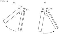
- an angle a formed between the reflection surface of the half mirror and the image display surface of the image display apparatus is set to be more than 0° and 45° or less.
- the orientation of the half mirror when an occupant attempts to view a reflected image i.e., when the half mirror mirrors the rear as the reflected image
- the orientation of the half mirror when the occupant attempts to view an image displayed on the image display apparatus i.e., when the occupant wishes to suppress an influence of the reflected image of the half mirror
- the angle formed between the reflection surface of the half mirror and the image display surface of the image display apparatus is preferably from 5° to 40°, more preferably from 10° to 30°.
- the polarizing plate typically has a polarizer and a protective layer arranged on one side, or each of both sides, of the polarizer.
- the polarizer is typically an absorption- type polarizer.
- the transmittance (also referred to as "single axis transmittance") of the polarizer at a wavelength of 589 nm is preferably 41% or more, more preferably 42% or more. It should be noted that a theoretical upper limit for the single axis transmittance is 50%. In addition, its polarization degree is preferably from 99.5% to 100%, more preferably from 99.9% to 100%.
- any appropriate polarizer may be used as the polarizer.
- a polarizer obtained by adsorbing a dichroic substance, such as iodine, onto a polyvinyl alcohol-based film and subj ecting the resultant film to uniaxial stretching is particularly preferred because of its high polarized dichromaticity.
- the polarizer has a thickness of preferably from 0.5 ⁇ m to 80 ⁇ m.
- the polarizer obtained by adsorbing iodine onto a polyvinyl alcohol-based film and subjecting the resultant film to uniaxial stretching is typically produced by dyeing polyvinyl alcohol through immersion in an aqueous solution of iodine and stretching the resultant film at a ratio of from 3 times to 7 times with respect to its original length.
- the stretching may be carried out after the dyeing, the stretching may be carried out during the dyeing, or the stretching may be carried out before the dyeing.
- the polarizer may be produced by subjecting the film to treatments such as swelling, cross-linking, adjusting, washing with water, and drying in addition to the stretching and the dyeing.
- any appropriate film may be used as the protective layer.
- cellulose-based resins such as triacetylcellulose (TAC); and transparent resins, such as (meth)acrylic, polyester-based, polyvinyl alcohol-based, polycarbonate-based, polyamide-based, polyimide-based, polyether sulfone-based, polysulfone-based, polystyrene-based, polynorbornene-based, polyolefin-based, or acetate-based transparent resins.
- TAC triacetylcellulose
- transparent resins such as (meth)acrylic, polyester-based, polyvinyl alcohol-based, polycarbonate-based, polyamide-based, polyimide-based, polyether sulfone-based, polysulfone-based, polystyrene-based, polynorbornene-based, polyolefin-based, or acetate-based transparent resins.
- examples thereof further include thermosetting resins and UV curable resins, such as acrylic, urethane-based, acrylic urethane-based, epoxy-based, or silicone-based thermosetting resins and UV curable resins.
- examples thereof further include glassy polymers, such as a siloxane-based polymer.
- a polymer film described in Japanese Patent Application Laid-open No. 2001-343529 International Patent WO01/37007A ) may also be used.
- a resin composition containing a thermoplastic resin having in its side chain a substituted or unsubstituted imide group and a thermoplastic resin having in its side chain a substituted or unsubstituted phenyl group and a nitrile group may be used as a material for the film.
- An example thereof is a resin composition containing an alternating copolymer formed of isobutene and N-methylmaleimide and an acrylonitrile-styrene copolymer.
- the polymer film may be, for example, an extruded product of the resin composition.
- any appropriate mirror can be used as the half mirror as long as the mirror can transmit part of incident light and reflect other part thereof.
- Examples thereof include: a half mirror including a transparent base material and a metal thin film formed on the transparent base material; and a half mirror including a transparent base material and a dielectric multilayer film formed on the transparent base material.
- the half mirror is preferably free of a polarization function from the viewpoint that the effect of arranging the first polarizing plate is efficiently obtained.
- any appropriate material can be used as a material for constituting the transparent base material.
- the material include: transparent resin materials, such as polymethyl methacrylate, polycarbonate, and an epoxy resin; and glass.
- the thickness of the transparent base material is, for example, from 20 ⁇ m to 5,000 ⁇ m.
- the transparent base material is preferably free of a retardation.
- a metal having a high light reflectance can be used as a material for constituting the metal thin film, and examples thereof include aluminum, silver, and tin.
- the metal thin film can be formed by, for example, plating or vapor deposition.
- the thickness of the metal thin film is, for example, from 2 nm to 80 nm, preferably from 3 nm to 50 nm.
- a high-refractive index material and a low-refractive index material each having a predetermined thickness are laminated so that the film has a function as a mirror.
- the high-refractive index material and the low-refractive index material are preferably laminated in an alternate manner, and the function as the half mirror is expressed by utilizing the interference of light beams occurring upon their incidence from the low-refractive index material to the high-refractive index material.
- the half mirror including the dielectric multilayer film is preferred because its absorption of light is reduced.
- the high-refractive index material has a refractive index of preferably more than 2.0, more preferably more than 2.0 and 3.0 or less.
- Specific examples of the high-refractive index material include ZnS-SiO 2 , TiO 2 , ZrO 2 , and Ta 2 O 3 .
- the low-refractive index material has a refractive index of preferably from 1.2 to 2.0, more preferably from 1.4 to 1.9.
- Specific examples of the low-refractive index material include SiO 2 , Al 2 O 3 , and MgF.
- the visible light reflectance of the half mirror is preferably from 20% to 80%, more preferably from 30% to 70%, still more preferably from 40% to 60%.
- the visible light transmittance of the half mirror is preferably from 20% to 80%, more preferably from 30% to 70%, still more preferably from 40% to 60%.
- the visible light reflectance, the visible light transmittance, and a ratio therebetween can be adjusted by controlling the thickness of the metal thin film or the dielectric multilayer film.
- the ratio between the visible light reflectance and visible light transmittance of the half mirror is preferably from 2:8 to 8:2, more preferably from 3:7 to 7:3, still more preferably from 4 : 6 to 6:4.
- the ratio between the visible light reflectance and the visible light transmittance can be appropriately adjusted in accordance with, for example, the brightness of the image display apparatus.
- the liquid crystal display apparatus includes a liquid crystal panel including a liquid crystal cell 131, the second polarizing plate 132 arranged on the viewer side of the liquid crystal cell 131, and a third polarizing plate 133 placed on the back surface side of the liquid crystal cell 131.
- the image display apparatus can include any appropriate other member (such as a backlight unit) as required.
- the second polarizingplate and the third polarizingplate can be arranged so that the absorption axes of their respective polarizers are substantially perpendicular or parallel to each other to enable the viewing of an image.
- the liquid crystal cell 131 has a pair of substrates and a liquid crystal layer serving as a display medium sandwiched between the substrates.
- a color filter and a black matrix are arranged on one of the substrates, and a switching element for controlling the electrooptical characteristics of a liquid crystal, a scanning line for providing the switching element with a gate signal and a signal line for providing the element with a source signal, and a pixel electrode and a counter electrode are arranged on the other substrate.
- An interval between the substrates (cell gap) can be controlled with, for example, a spacer.
- an alignment film formed of polyimide can be arranged on the side of each of the substrates to be brought into contact with the liquid crystal layer.
- the liquid crystal layer contains liquid crystal molecules aligned in a homogeneous array under a state in which no electric field is present.
- Typical examples of a driving mode using the liquid crystal layer showing such three-dimensional refractive index include an in-plane switching (IPS) mode and a fringe field switching (FFS) mode.
- IPS in-plane switching
- FFS fringe field switching
- the IPS mode includes a super in-plane switching (S-IPS) mode and an advanced super in-plane switching (AS-IPS) mode each adopting a V-shaped electrode, a zigzag electrode, or the like.
- the FFS mode includes an advanced fringe field switching (A-FFS) mode and an ultra fringe field switching (U-FFS) mode each adopting a V-shaped electrode, a zigzag electrode, or the like.
- the liquid crystal layer contains liquid crystal molecules aligned in a homeotropic array under a state in which no electric field is present.
- a driving mode using the liquid crystal molecules aligned in the homeotropic array under a state in which no electric field is present is, for example, a vertical alignment (VA) mode.
- VA mode includes a multi-domain VA (MVA) mode.
- Such polarizing plate as described in the section B is used as each of the second polarizing plate and the third polarizing plate.
- the second polarizing plate 132 is omitted from the image display apparatus (liquid crystal display apparatus) 130 illustrated in FIG. 1 . That is, in this embodiment, a liquid crystal display apparatus free of a polarizing plate on the viewer side of its liquid crystal cell is used. In this case, the first polarizing plate and the third polarizing plate are arranged so that the absorption axes of their respective polarizers are substantially perpendicular or parallel to each other to enable the viewing of an image. In this embodiment, the brightness of the image display mirror for a vehicle can be improved because an optical loss due to the second polarizing plate can be eliminated.
- the ⁇ /4 plate is arranged on the viewer side (i.e., the side opposite to the half mirror) of the first polarizing plate.
- a front retardation R 0 of the A/4 plate at a wavelength of 590 nm is from 90 nm to 190 nm, preferably from 100 nm to 180 nm, more preferably from 110 nm to 170 nm.
- the A/4 plate shows any appropriate refractive index ellipsoid as long as the plate has the relationship of nx>ny.
- the refractive index ellipsoid of the A/4 plate shows the relationship of nx>nz>ny or nx>ny ⁇ nz.
- An angle between the absorption axis of the polarizer of the first polarizing plate and the slow axis of the A/4 plate is preferably from +40° to +50° or from -40° to -50°, more preferably from +43° to +47° or from -43° to -47°, still more preferably +45° or -45°.
- the laminated structure of the first polarizing plate and the ⁇ /4 plate can function as a circularly polarizing plate.
- a typical example thereof is a stretched film of a polymer film.
- a resin for forming the polymer film include a polycarbonate-based resin and a cycloolefin-based resin.
- a method of producing the ⁇ /4 plate is not particularly limited, but the A/4 plate can be obtained by, for example, stretching the polymer film at a temperature of from about 100°C to about 250°C and at a stretching ratio of from about 1.1 times to about 2.5 times.
- the front retardation and thickness direction retardation of the ⁇ /4 plate can be controlled by adjusting the stretching ratio and stretching temperature of the polymer film.
- the thickness and total light transmittance of the A/4 plate are preferably about 200 ⁇ m or less and 80% or more, respectively, though the thickness and the total light transmittance are not particularly limited thereto.
Landscapes
- Engineering & Computer Science (AREA)
- Multimedia (AREA)
- Mechanical Engineering (AREA)
- Physics & Mathematics (AREA)
- General Physics & Mathematics (AREA)
- Optics & Photonics (AREA)
- Chemical & Material Sciences (AREA)
- Crystallography & Structural Chemistry (AREA)
- Spectroscopy & Molecular Physics (AREA)
- Theoretical Computer Science (AREA)
- Polarising Elements (AREA)
- Liquid Crystal (AREA)
- Optical Elements Other Than Lenses (AREA)
- Devices For Indicating Variable Information By Combining Individual Elements (AREA)
Claims (2)
- Bildanzeigespiegel (100) für ein Fahrzeug, der eine erste polarisierende Scheibe (110), einen Halbspiegel (120) und ein Bildanzeigegerät (130) in der erwähnten Reihenfolge von einer Betrachterseite her umfasst; wobeidas Bildanzeigegerät (130) eine zweite polarisierende Platte beinhaltet, die einen Absorptionstyp-Polarizer beinhaltet;wobei die erste polarisierende Platte (110) einen Absorptionstyp-Polarizer aufweist, wobei eine Richtung einer Absorptionsachse des Polarizers derart eingestellt ist, dass ein Transmissionsgrad des Lichts, das von dem Bildanzeigegerät (130) abgegeben wird, das durch die erste polarisierende Platte (110) übertragen wird, maximal wird, und wobeieine Absorptionsachse des Polarizers der zweiten polarisierenden Platte und die Absorptionsachse des Polarizers der ersten polarisierenden Platte (110) im Wesentlichen zueinander parallel sind, wobei die erste polarisierende Platte (110) und der Halbspiegel (120) durch Zwischenschichtfüllen in engen Kontakt miteinander gebracht werden, und wobei der Halbspiegel (120) und das Bildanzeigegerät (130) durch Zwischenschichtfüllen in engen Kontakt miteinander gebracht werden.
- Bildanzeigespiegel (100) für ein Fahrzeug nach Anspruch 1, der weiter eine λ/4-Platte auf einer Betrachterseite der ersten polarisierenden Platte (110) her umfasst.
Applications Claiming Priority (1)
| Application Number | Priority Date | Filing Date | Title |
|---|---|---|---|
| JP2015005098A JP6571935B2 (ja) | 2015-01-14 | 2015-01-14 | 車両用映像表示ミラー |
Publications (2)
| Publication Number | Publication Date |
|---|---|
| EP3045353A1 EP3045353A1 (de) | 2016-07-20 |
| EP3045353B1 true EP3045353B1 (de) | 2022-10-19 |
Family
ID=55229521
Family Applications (1)
| Application Number | Title | Priority Date | Filing Date |
|---|---|---|---|
| EP16151040.9A Active EP3045353B1 (de) | 2015-01-14 | 2016-01-13 | Bildanzeigespiegel für ein fahrzeug |
Country Status (5)
| Country | Link |
|---|---|
| US (1) | US10377312B2 (de) |
| EP (1) | EP3045353B1 (de) |
| JP (1) | JP6571935B2 (de) |
| KR (1) | KR102418069B1 (de) |
| CN (1) | CN105788476B (de) |
Families Citing this family (15)
| Publication number | Priority date | Publication date | Assignee | Title |
|---|---|---|---|---|
| CA2807615C (en) | 2012-03-08 | 2020-06-30 | Simplehuman, Llc | Vanity mirror |
| US10076176B2 (en) | 2015-03-06 | 2018-09-18 | Simplehuman, Llc | Vanity mirror comprising light sources and methods of manufacture thereof |
| CN108303816A (zh) * | 2017-01-12 | 2018-07-20 | 江苏集萃智能液晶科技有限公司 | 一种具有显示功能的后视镜 |
| US10869537B2 (en) | 2017-03-17 | 2020-12-22 | Simplehuman, Llc | Vanity mirror |
| US11026497B2 (en) | 2018-02-14 | 2021-06-08 | Simplehuman, Llc | Compact mirror |
| US11708031B2 (en) | 2018-03-22 | 2023-07-25 | Simplehuman, Llc | Voice-activated vanity mirror |
| JP7142318B2 (ja) * | 2018-03-29 | 2022-09-27 | パナソニックIpマネジメント株式会社 | 表示装置 |
| CA3113402A1 (en) | 2018-09-19 | 2020-03-26 | Simplehuman, Llc | Vanity mirror |
| USD925928S1 (en) | 2019-03-01 | 2021-07-27 | Simplehuman, Llc | Vanity mirror |
| US11640042B2 (en) | 2019-03-01 | 2023-05-02 | Simplehuman, Llc | Vanity mirror |
| USD927863S1 (en) | 2019-05-02 | 2021-08-17 | Simplehuman, Llc | Vanity mirror cover |
| JP2021162793A (ja) * | 2020-04-02 | 2021-10-11 | 日東電工株式会社 | 車両の内装構造 |
| CN111439204B (zh) * | 2020-04-30 | 2022-01-28 | 北京京东方技术开发有限公司 | 一种防眩显示装置、防眩显示方法和车内后视镜 |
| CN112150940B (zh) * | 2020-09-22 | 2024-05-14 | 郑州胜龙信息技术股份有限公司 | 一种用于信息安全防护的光栅式屏幕显示系统 |
| CA3230834A1 (en) | 2023-03-03 | 2025-06-27 | Simplehuman, Llc | Vanity mirror with hidden sensor |
Family Cites Families (34)
| Publication number | Priority date | Publication date | Assignee | Title |
|---|---|---|---|---|
| JPS60169620U (ja) * | 1984-04-20 | 1985-11-11 | トヨタ自動車株式会社 | 液晶防眩ミラ− |
| HRP930244A2 (en) * | 1993-03-01 | 1995-08-31 | Kre O Tisaj | Inside rear-view mirror supressing specular reflections coming from a rear window |
| JPH09182112A (ja) * | 1995-12-22 | 1997-07-11 | Sharp Corp | 小型光学系を用いたプロジェクタ装置 |
| DE19631409A1 (de) | 1996-08-05 | 1998-02-12 | Juergen Dipl Ing Heinz | Baugruppe mit veränderbarer Transmission und Reflexbeschichtung |
| JPH11183895A (ja) * | 1997-12-25 | 1999-07-09 | Nippon Seiki Co Ltd | 表示装置 |
| WO2001037007A1 (en) | 1999-11-12 | 2001-05-25 | Kaneka Corporation | Transparent film |
| JP2001343529A (ja) | 2000-03-30 | 2001-12-14 | Kanegafuchi Chem Ind Co Ltd | 偏光子保護フィルムおよびその製造方法 |
| TWI266907B (en) * | 2002-07-24 | 2006-11-21 | Nitto Denko Corp | Polarizing device, optical thin film using the same, and image display device using the same |
| JP4332721B2 (ja) * | 2003-12-16 | 2009-09-16 | フジノン株式会社 | 偏光変換素子及び偏光変換素子を含む光学装置 |
| US7502156B2 (en) | 2004-07-12 | 2009-03-10 | Gentex Corporation | Variable reflectance mirrors and windows |
| US8545030B2 (en) * | 2004-07-12 | 2013-10-01 | Gentex Corporation | Rearview mirror assemblies with anisotropic polymer laminates |
| US8282224B2 (en) | 2004-07-12 | 2012-10-09 | Gentex Corporation | Rearview mirror assemblies with anisotropic polymer laminates |
| JP2006106180A (ja) * | 2004-10-01 | 2006-04-20 | Nitto Denko Corp | 光学フィルムおよび画像表示装置 |
| US20070146481A1 (en) * | 2005-12-12 | 2007-06-28 | Volkswagen Ag | Rear view mirror for a motor vehicle |
| US7859753B2 (en) * | 2005-12-21 | 2010-12-28 | Chem Image Corporation | Optical birefringence filters with interleaved absorptive and zero degree reflective polarizers |
| JP5577038B2 (ja) * | 2006-03-09 | 2014-08-20 | ジェンテックス コーポレイション | 高輝度ディスプレイを含む車両リアビューアセンブリ |
| JP2008070604A (ja) * | 2006-09-14 | 2008-03-27 | Canon Inc | 画像表示装置 |
| JP4418483B2 (ja) * | 2007-06-28 | 2010-02-17 | 株式会社村上開明堂 | 液晶防眩ミラー |
| US9254789B2 (en) * | 2008-07-10 | 2016-02-09 | Gentex Corporation | Rearview mirror assemblies with anisotropic polymer laminates |
| JP5591801B2 (ja) * | 2008-07-10 | 2014-09-17 | ジェンテックス コーポレイション | 異方性ポリマー積層体を有するバックミラーアセンブリ |
| US8290139B2 (en) * | 2008-07-30 | 2012-10-16 | Cisco Technology, Inc. | Method and apparatus for maintaining dynamic queues in call centers using social network information |
| JP2010221899A (ja) * | 2009-03-24 | 2010-10-07 | Murakami Corp | モニター付車両用ミラー |
| JP5506411B2 (ja) * | 2010-01-12 | 2014-05-28 | スタンレー電気株式会社 | モニター付きミラーアッセンブリ |
| JP5152309B2 (ja) * | 2010-12-01 | 2013-02-27 | 株式会社デンソー | 電子ミラー |
| CN102887114B (zh) * | 2011-07-18 | 2015-02-04 | 宏腾光电股份有限公司 | 车用显示镜及其制作方法 |
| CN102495495B (zh) * | 2011-10-28 | 2015-03-11 | 友达光电股份有限公司 | 具可透视性的显示装置及其使用的影像显示方法 |
| BR112014010605B1 (pt) | 2011-12-09 | 2020-09-15 | Nissan Motor Co., Ltd | Espelho de exibição de vídeo e sistema de espelho de exibição de vídeo |
| CN104919364B (zh) * | 2013-01-16 | 2017-11-14 | 夏普株式会社 | 反射镜显示器、半反射镜板和电子设备 |
| CN105474291B (zh) * | 2013-08-05 | 2018-06-22 | 夏普株式会社 | 反射镜显示器、半反射镜板和电子设备 |
| CN105774658B (zh) * | 2015-01-14 | 2020-10-16 | 日东电工株式会社 | 车辆用影像显示镜 |
| JP6457284B2 (ja) * | 2015-02-02 | 2019-01-23 | 日東電工株式会社 | 車両用映像表示ミラー |
| JP6441098B2 (ja) * | 2015-02-02 | 2018-12-19 | 日東電工株式会社 | 車両用映像表示ミラー |
| JP6425570B2 (ja) * | 2015-02-02 | 2018-11-21 | 日東電工株式会社 | 映像表示装置付のミラーを備える車両 |
| JP6457283B2 (ja) * | 2015-02-02 | 2019-01-23 | 日東電工株式会社 | 車両用映像表示ミラー |
-
2015
- 2015-01-14 JP JP2015005098A patent/JP6571935B2/ja active Active
-
2016
- 2016-01-12 KR KR1020160003665A patent/KR102418069B1/ko active Active
- 2016-01-12 CN CN201610016407.2A patent/CN105788476B/zh active Active
- 2016-01-13 US US14/994,620 patent/US10377312B2/en active Active
- 2016-01-13 EP EP16151040.9A patent/EP3045353B1/de active Active
Also Published As
| Publication number | Publication date |
|---|---|
| US20160200256A1 (en) | 2016-07-14 |
| JP6571935B2 (ja) | 2019-09-04 |
| KR102418069B1 (ko) | 2022-07-07 |
| KR20160087760A (ko) | 2016-07-22 |
| CN105788476A (zh) | 2016-07-20 |
| EP3045353A1 (de) | 2016-07-20 |
| CN105788476B (zh) | 2020-12-29 |
| US10377312B2 (en) | 2019-08-13 |
| JP2016130097A (ja) | 2016-07-21 |
Similar Documents
| Publication | Publication Date | Title |
|---|---|---|
| EP3045353B1 (de) | Bildanzeigespiegel für ein fahrzeug | |
| EP3045352B1 (de) | Bildanzeigespiegel für ein fahrzeug | |
| EP3050753B1 (de) | Bildanzeigespiegel für ein fahrzeug | |
| EP3050726B1 (de) | Fahrzeug mit spiegel mit bildanzeigevorrichtung | |
| EP3051338B1 (de) | Bildanzeigespiegel für ein fahrzeug | |
| EP3050754B1 (de) | Bildanzeigespiegel für ein fahrzeug | |
| KR102470716B1 (ko) | 차량용 영상 표시 미러 |
Legal Events
| Date | Code | Title | Description |
|---|---|---|---|
| PUAI | Public reference made under article 153(3) epc to a published international application that has entered the european phase |
Free format text: ORIGINAL CODE: 0009012 |
|
| AK | Designated contracting states |
Kind code of ref document: A1 Designated state(s): AL AT BE BG CH CY CZ DE DK EE ES FI FR GB GR HR HU IE IS IT LI LT LU LV MC MK MT NL NO PL PT RO RS SE SI SK SM TR |
|
| AX | Request for extension of the european patent |
Extension state: BA ME |
|
| STAA | Information on the status of an ep patent application or granted ep patent |
Free format text: STATUS: REQUEST FOR EXAMINATION WAS MADE |
|
| 17P | Request for examination filed |
Effective date: 20170117 |
|
| RBV | Designated contracting states (corrected) |
Designated state(s): AL AT BE BG CH CY CZ DE DK EE ES FI FR GB GR HR HU IE IS IT LI LT LU LV MC MK MT NL NO PL PT RO RS SE SI SK SM TR |
|
| STAA | Information on the status of an ep patent application or granted ep patent |
Free format text: STATUS: EXAMINATION IS IN PROGRESS |
|
| 17Q | First examination report despatched |
Effective date: 20190918 |
|
| GRAP | Despatch of communication of intention to grant a patent |
Free format text: ORIGINAL CODE: EPIDOSNIGR1 |
|
| STAA | Information on the status of an ep patent application or granted ep patent |
Free format text: STATUS: GRANT OF PATENT IS INTENDED |
|
| RIC1 | Information provided on ipc code assigned before grant |
Ipc: G02B 5/08 20060101ALN20220524BHEP Ipc: G02B 5/30 20060101ALN20220524BHEP Ipc: B60R 1/08 20060101AFI20220524BHEP |
|
| INTG | Intention to grant announced |
Effective date: 20220627 |
|
| GRAS | Grant fee paid |
Free format text: ORIGINAL CODE: EPIDOSNIGR3 |
|
| GRAA | (expected) grant |
Free format text: ORIGINAL CODE: 0009210 |
|
| STAA | Information on the status of an ep patent application or granted ep patent |
Free format text: STATUS: THE PATENT HAS BEEN GRANTED |
|
| AK | Designated contracting states |
Kind code of ref document: B1 Designated state(s): AL AT BE BG CH CY CZ DE DK EE ES FI FR GB GR HR HU IE IS IT LI LT LU LV MC MK MT NL NO PL PT RO RS SE SI SK SM TR |
|
| REG | Reference to a national code |
Ref country code: GB Ref legal event code: FG4D |
|
| REG | Reference to a national code |
Ref country code: CH Ref legal event code: EP |
|
| REG | Reference to a national code |
Ref country code: DE Ref legal event code: R096 Ref document number: 602016075691 Country of ref document: DE |
|
| REG | Reference to a national code |
Ref country code: IE Ref legal event code: FG4D |
|
| REG | Reference to a national code |
Ref country code: AT Ref legal event code: REF Ref document number: 1525378 Country of ref document: AT Kind code of ref document: T Effective date: 20221115 |
|
| REG | Reference to a national code |
Ref country code: LT Ref legal event code: MG9D |
|
| REG | Reference to a national code |
Ref country code: NL Ref legal event code: MP Effective date: 20221019 |
|
| REG | Reference to a national code |
Ref country code: AT Ref legal event code: MK05 Ref document number: 1525378 Country of ref document: AT Kind code of ref document: T Effective date: 20221019 |
|
| PG25 | Lapsed in a contracting state [announced via postgrant information from national office to epo] |
Ref country code: NL Free format text: LAPSE BECAUSE OF FAILURE TO SUBMIT A TRANSLATION OF THE DESCRIPTION OR TO PAY THE FEE WITHIN THE PRESCRIBED TIME-LIMIT Effective date: 20221019 |
|
| PG25 | Lapsed in a contracting state [announced via postgrant information from national office to epo] |
Ref country code: SE Free format text: LAPSE BECAUSE OF FAILURE TO SUBMIT A TRANSLATION OF THE DESCRIPTION OR TO PAY THE FEE WITHIN THE PRESCRIBED TIME-LIMIT Effective date: 20221019 Ref country code: PT Free format text: LAPSE BECAUSE OF FAILURE TO SUBMIT A TRANSLATION OF THE DESCRIPTION OR TO PAY THE FEE WITHIN THE PRESCRIBED TIME-LIMIT Effective date: 20230220 Ref country code: NO Free format text: LAPSE BECAUSE OF FAILURE TO SUBMIT A TRANSLATION OF THE DESCRIPTION OR TO PAY THE FEE WITHIN THE PRESCRIBED TIME-LIMIT Effective date: 20230119 Ref country code: LT Free format text: LAPSE BECAUSE OF FAILURE TO SUBMIT A TRANSLATION OF THE DESCRIPTION OR TO PAY THE FEE WITHIN THE PRESCRIBED TIME-LIMIT Effective date: 20221019 Ref country code: FI Free format text: LAPSE BECAUSE OF FAILURE TO SUBMIT A TRANSLATION OF THE DESCRIPTION OR TO PAY THE FEE WITHIN THE PRESCRIBED TIME-LIMIT Effective date: 20221019 Ref country code: ES Free format text: LAPSE BECAUSE OF FAILURE TO SUBMIT A TRANSLATION OF THE DESCRIPTION OR TO PAY THE FEE WITHIN THE PRESCRIBED TIME-LIMIT Effective date: 20221019 Ref country code: AT Free format text: LAPSE BECAUSE OF FAILURE TO SUBMIT A TRANSLATION OF THE DESCRIPTION OR TO PAY THE FEE WITHIN THE PRESCRIBED TIME-LIMIT Effective date: 20221019 |
|
| PG25 | Lapsed in a contracting state [announced via postgrant information from national office to epo] |
Ref country code: RS Free format text: LAPSE BECAUSE OF FAILURE TO SUBMIT A TRANSLATION OF THE DESCRIPTION OR TO PAY THE FEE WITHIN THE PRESCRIBED TIME-LIMIT Effective date: 20221019 Ref country code: PL Free format text: LAPSE BECAUSE OF FAILURE TO SUBMIT A TRANSLATION OF THE DESCRIPTION OR TO PAY THE FEE WITHIN THE PRESCRIBED TIME-LIMIT Effective date: 20221019 Ref country code: LV Free format text: LAPSE BECAUSE OF FAILURE TO SUBMIT A TRANSLATION OF THE DESCRIPTION OR TO PAY THE FEE WITHIN THE PRESCRIBED TIME-LIMIT Effective date: 20221019 Ref country code: IS Free format text: LAPSE BECAUSE OF FAILURE TO SUBMIT A TRANSLATION OF THE DESCRIPTION OR TO PAY THE FEE WITHIN THE PRESCRIBED TIME-LIMIT Effective date: 20230219 Ref country code: HR Free format text: LAPSE BECAUSE OF FAILURE TO SUBMIT A TRANSLATION OF THE DESCRIPTION OR TO PAY THE FEE WITHIN THE PRESCRIBED TIME-LIMIT Effective date: 20221019 Ref country code: GR Free format text: LAPSE BECAUSE OF FAILURE TO SUBMIT A TRANSLATION OF THE DESCRIPTION OR TO PAY THE FEE WITHIN THE PRESCRIBED TIME-LIMIT Effective date: 20230120 |
|
| REG | Reference to a national code |
Ref country code: DE Ref legal event code: R097 Ref document number: 602016075691 Country of ref document: DE |
|
| PG25 | Lapsed in a contracting state [announced via postgrant information from national office to epo] |
Ref country code: SM Free format text: LAPSE BECAUSE OF FAILURE TO SUBMIT A TRANSLATION OF THE DESCRIPTION OR TO PAY THE FEE WITHIN THE PRESCRIBED TIME-LIMIT Effective date: 20221019 Ref country code: RO Free format text: LAPSE BECAUSE OF FAILURE TO SUBMIT A TRANSLATION OF THE DESCRIPTION OR TO PAY THE FEE WITHIN THE PRESCRIBED TIME-LIMIT Effective date: 20221019 Ref country code: EE Free format text: LAPSE BECAUSE OF FAILURE TO SUBMIT A TRANSLATION OF THE DESCRIPTION OR TO PAY THE FEE WITHIN THE PRESCRIBED TIME-LIMIT Effective date: 20221019 Ref country code: DK Free format text: LAPSE BECAUSE OF FAILURE TO SUBMIT A TRANSLATION OF THE DESCRIPTION OR TO PAY THE FEE WITHIN THE PRESCRIBED TIME-LIMIT Effective date: 20221019 Ref country code: CZ Free format text: LAPSE BECAUSE OF FAILURE TO SUBMIT A TRANSLATION OF THE DESCRIPTION OR TO PAY THE FEE WITHIN THE PRESCRIBED TIME-LIMIT Effective date: 20221019 |
|
| PLBE | No opposition filed within time limit |
Free format text: ORIGINAL CODE: 0009261 |
|
| STAA | Information on the status of an ep patent application or granted ep patent |
Free format text: STATUS: NO OPPOSITION FILED WITHIN TIME LIMIT |
|
| PG25 | Lapsed in a contracting state [announced via postgrant information from national office to epo] |
Ref country code: SK Free format text: LAPSE BECAUSE OF FAILURE TO SUBMIT A TRANSLATION OF THE DESCRIPTION OR TO PAY THE FEE WITHIN THE PRESCRIBED TIME-LIMIT Effective date: 20221019 Ref country code: AL Free format text: LAPSE BECAUSE OF FAILURE TO SUBMIT A TRANSLATION OF THE DESCRIPTION OR TO PAY THE FEE WITHIN THE PRESCRIBED TIME-LIMIT Effective date: 20221019 |
|
| REG | Reference to a national code |
Ref country code: CH Ref legal event code: PL |
|
| 26N | No opposition filed |
Effective date: 20230720 |
|
| GBPC | Gb: european patent ceased through non-payment of renewal fee |
Effective date: 20230119 |
|
| PG25 | Lapsed in a contracting state [announced via postgrant information from national office to epo] |
Ref country code: LU Free format text: LAPSE BECAUSE OF NON-PAYMENT OF DUE FEES Effective date: 20230113 |
|
| REG | Reference to a national code |
Ref country code: BE Ref legal event code: MM Effective date: 20230131 |
|
| PG25 | Lapsed in a contracting state [announced via postgrant information from national office to epo] |
Ref country code: LI Free format text: LAPSE BECAUSE OF NON-PAYMENT OF DUE FEES Effective date: 20230131 Ref country code: GB Free format text: LAPSE BECAUSE OF NON-PAYMENT OF DUE FEES Effective date: 20230119 Ref country code: CH Free format text: LAPSE BECAUSE OF NON-PAYMENT OF DUE FEES Effective date: 20230131 |
|
| PG25 | Lapsed in a contracting state [announced via postgrant information from national office to epo] |
Ref country code: SI Free format text: LAPSE BECAUSE OF FAILURE TO SUBMIT A TRANSLATION OF THE DESCRIPTION OR TO PAY THE FEE WITHIN THE PRESCRIBED TIME-LIMIT Effective date: 20221019 Ref country code: BE Free format text: LAPSE BECAUSE OF NON-PAYMENT OF DUE FEES Effective date: 20230131 |
|
| PG25 | Lapsed in a contracting state [announced via postgrant information from national office to epo] |
Ref country code: IE Free format text: LAPSE BECAUSE OF NON-PAYMENT OF DUE FEES Effective date: 20230113 |
|
| PG25 | Lapsed in a contracting state [announced via postgrant information from national office to epo] |
Ref country code: IT Free format text: LAPSE BECAUSE OF FAILURE TO SUBMIT A TRANSLATION OF THE DESCRIPTION OR TO PAY THE FEE WITHIN THE PRESCRIBED TIME-LIMIT Effective date: 20221019 |
|
| PG25 | Lapsed in a contracting state [announced via postgrant information from national office to epo] |
Ref country code: MC Free format text: LAPSE BECAUSE OF FAILURE TO SUBMIT A TRANSLATION OF THE DESCRIPTION OR TO PAY THE FEE WITHIN THE PRESCRIBED TIME-LIMIT Effective date: 20221019 |
|
| PG25 | Lapsed in a contracting state [announced via postgrant information from national office to epo] |
Ref country code: MC Free format text: LAPSE BECAUSE OF FAILURE TO SUBMIT A TRANSLATION OF THE DESCRIPTION OR TO PAY THE FEE WITHIN THE PRESCRIBED TIME-LIMIT Effective date: 20221019 |
|
| PG25 | Lapsed in a contracting state [announced via postgrant information from national office to epo] |
Ref country code: BG Free format text: LAPSE BECAUSE OF FAILURE TO SUBMIT A TRANSLATION OF THE DESCRIPTION OR TO PAY THE FEE WITHIN THE PRESCRIBED TIME-LIMIT Effective date: 20221019 |
|
| PG25 | Lapsed in a contracting state [announced via postgrant information from national office to epo] |
Ref country code: BG Free format text: LAPSE BECAUSE OF FAILURE TO SUBMIT A TRANSLATION OF THE DESCRIPTION OR TO PAY THE FEE WITHIN THE PRESCRIBED TIME-LIMIT Effective date: 20221019 |
|
| PG25 | Lapsed in a contracting state [announced via postgrant information from national office to epo] |
Ref country code: CY Free format text: LAPSE BECAUSE OF FAILURE TO SUBMIT A TRANSLATION OF THE DESCRIPTION OR TO PAY THE FEE WITHIN THE PRESCRIBED TIME-LIMIT; INVALID AB INITIO Effective date: 20160113 |
|
| PG25 | Lapsed in a contracting state [announced via postgrant information from national office to epo] |
Ref country code: HU Free format text: LAPSE BECAUSE OF FAILURE TO SUBMIT A TRANSLATION OF THE DESCRIPTION OR TO PAY THE FEE WITHIN THE PRESCRIBED TIME-LIMIT; INVALID AB INITIO Effective date: 20160113 |
|
| PG25 | Lapsed in a contracting state [announced via postgrant information from national office to epo] |
Ref country code: TR Free format text: LAPSE BECAUSE OF FAILURE TO SUBMIT A TRANSLATION OF THE DESCRIPTION OR TO PAY THE FEE WITHIN THE PRESCRIBED TIME-LIMIT Effective date: 20221019 |
|
| PGFP | Annual fee paid to national office [announced via postgrant information from national office to epo] |
Ref country code: FR Payment date: 20251128 Year of fee payment: 11 |
|
| PGFP | Annual fee paid to national office [announced via postgrant information from national office to epo] |
Ref country code: DE Payment date: 20251203 Year of fee payment: 11 |