EP3045217B1 - Druckwechseladsorptionsvorrichtung - Google Patents
Druckwechseladsorptionsvorrichtung Download PDFInfo
- Publication number
- EP3045217B1 EP3045217B1 EP13893669.5A EP13893669A EP3045217B1 EP 3045217 B1 EP3045217 B1 EP 3045217B1 EP 13893669 A EP13893669 A EP 13893669A EP 3045217 B1 EP3045217 B1 EP 3045217B1
- Authority
- EP
- European Patent Office
- Prior art keywords
- contact end
- rotor
- housing
- exhaust port
- contact
- Prior art date
- Legal status (The legal status is an assumption and is not a legal conclusion. Google has not performed a legal analysis and makes no representation as to the accuracy of the status listed.)
- Active
Links
Images


Classifications
-
- B—PERFORMING OPERATIONS; TRANSPORTING
- B01—PHYSICAL OR CHEMICAL PROCESSES OR APPARATUS IN GENERAL
- B01D—SEPARATION
- B01D53/00—Separation of gases or vapours; Recovering vapours of volatile solvents from gases; Chemical or biological purification of waste gases, e.g. engine exhaust gases, smoke, fumes, flue gases, aerosols
- B01D53/02—Separation of gases or vapours; Recovering vapours of volatile solvents from gases; Chemical or biological purification of waste gases, e.g. engine exhaust gases, smoke, fumes, flue gases, aerosols by adsorption, e.g. preparative gas chromatography
- B01D53/06—Separation of gases or vapours; Recovering vapours of volatile solvents from gases; Chemical or biological purification of waste gases, e.g. engine exhaust gases, smoke, fumes, flue gases, aerosols by adsorption, e.g. preparative gas chromatography with moving adsorbents, e.g. rotating beds
-
- B—PERFORMING OPERATIONS; TRANSPORTING
- B01—PHYSICAL OR CHEMICAL PROCESSES OR APPARATUS IN GENERAL
- B01D—SEPARATION
- B01D53/00—Separation of gases or vapours; Recovering vapours of volatile solvents from gases; Chemical or biological purification of waste gases, e.g. engine exhaust gases, smoke, fumes, flue gases, aerosols
- B01D53/02—Separation of gases or vapours; Recovering vapours of volatile solvents from gases; Chemical or biological purification of waste gases, e.g. engine exhaust gases, smoke, fumes, flue gases, aerosols by adsorption, e.g. preparative gas chromatography
- B01D53/04—Separation of gases or vapours; Recovering vapours of volatile solvents from gases; Chemical or biological purification of waste gases, e.g. engine exhaust gases, smoke, fumes, flue gases, aerosols by adsorption, e.g. preparative gas chromatography with stationary adsorbents
- B01D53/047—Pressure swing adsorption
-
- B—PERFORMING OPERATIONS; TRANSPORTING
- B01—PHYSICAL OR CHEMICAL PROCESSES OR APPARATUS IN GENERAL
- B01D—SEPARATION
- B01D2253/00—Adsorbents used in seperation treatment of gases and vapours
- B01D2253/10—Inorganic adsorbents
- B01D2253/106—Silica or silicates
- B01D2253/108—Zeolites
-
- B—PERFORMING OPERATIONS; TRANSPORTING
- B01—PHYSICAL OR CHEMICAL PROCESSES OR APPARATUS IN GENERAL
- B01D—SEPARATION
- B01D2253/00—Adsorbents used in seperation treatment of gases and vapours
- B01D2253/10—Inorganic adsorbents
- B01D2253/116—Molecular sieves other than zeolites
-
- B—PERFORMING OPERATIONS; TRANSPORTING
- B01—PHYSICAL OR CHEMICAL PROCESSES OR APPARATUS IN GENERAL
- B01D—SEPARATION
- B01D2259/00—Type of treatment
- B01D2259/40—Further details for adsorption processes and devices
- B01D2259/40003—Methods relating to valve switching
Definitions
- the invention relates to a pressure swing adsorption device, which is mainly applied to the technical field of gas medium separation.
- PSA Pressure swing adsorption
- the working principle of PSA is as follows: utilizing the differences of "adsorption" capabilities of adsorbent molecular sieves towards different gas molecules to separate gas mixtures; after adsorption equilibrium, according to the property that the molecular sieve adsorbs different quantity of gas under different pressures, lowering pressure so that the molecular sieve desorbs the adsorbed gas, the process of which is called regeneration.
- two or more columns connected in parallel are generally used in a pressure swing adsorption device, so that pressurization adsorption and depressurization regeneration can be conducted alternately, producing continuous product gas.
- FIG. 3 Currently, most of the pressure swing adsorption devices in the market, shown in FIG. 3 , primarily utilize molecular sieves to separate the gas entered into an adsorption column (tank) 3' through a conduit 2' after being compressed by a conventional compressor 1'.
- the conduit 2' is provided with a valve 4' thereon.
- Such a device has the following drawbacks: a separated design, excessive parts, a bulky size, a loose structure, high pipe consumption and valve wear, low gas efficiency per unit power, requiring a complex control circuit, resulting in difficulties in synchronization control, poor reliability, and high cost.
- JP 2007 237004 A describes a pressure swing absorption apparatus in which a circular piston rotates eccentrically within a circular pump chamber, a moving blade forming a seal with the piston to divide the pump chamber into two volumes.
- US 3 945 345 A describes a rotary internal combustion engine having a generally square piston which rotates orbitally the within a trilobal chamber.
- US 2008/226480 A1 describes a rotary vacuum pump in which a generally triangular piston rotates orbitally the within a two-lobed chamber.
- the present invention provides a pressure swing adsorption device as defined in claim 1.
- the device has a simple and compact structure, requiring no complex gas pipeline with an easy synchronization control, and omits a corresponding magnetic valve and a complex control circuit seen in a conventional device.
- a pressure swing adsorption device comprising:
- the individual cavities rotate with the rotor sequentially pass through the gas inlet, the gas outlet, and the exhaust port in each working cycle.
- the center of the rotor is not coincident with the center of the housing, and the center of the rotor rotates around the center of the housing during the rotor rotation.
- the pressure swing adsorption device further comprises a central shaft having an external gear, located at the center of the housing and driven by a motor to rotate, an internal gear being provided at the center of the rotor, the external gear of the central shaft being meshed with the internal gear of the rotor, and the external gear having fewer teeth than the internal gear.
- a pressure relief valve is provided at the gas outlet.
- the rotor is provided with three contact ends arranged clockwise, maintaining a non-stop sliding contact with the inner surface of the housing: a first contact end, a second contact end, and a third contact end; three air cavities are formed between the external surface of the rotor and the inner surface of the housing, and adsorption chambers corresponding to the three air cavities respectively are provided: a first adsorption chamber, a second adsorption chamber, and a third adsorption chamber, wherein the first adsorption chamber is between the first contact end and the second contact end, the second adsorption chamber is between the second contact end and the third contact end, and the third adsorption chamber is between the third contact end and the first contact end; the housing is provided with one gas outlet, one gas inlet, and one exhaust port; when the device is in an initial position, the first contact end of the rotor is at the clockwise side of the gas inlet, and the third contact end is at the counterclockwise side of the exhaust port, with the gas in
- R is a generating radius
- e is a distance between the center of the rotor and the center of the housing
- t is time.
- the rotor is provided with four contact ends arranged clockwise, maintaining a non-stop sliding contact with the inner surface of the housing: a first contact end, a second contact end, a third contact end, and a fourth contact end; four air cavities are formed between the external surface of the rotor and the inner surface of the housing, and adsorption chambers corresponding to the four air cavities respectively are provided inside the rotor: a first adsorption chamber, a second adsorption chamber, a third adsorption chamber, and a fourth adsorption chamber, wherein the first adsorption chamber is between the first contact end and the second contact end, the second adsorption chamber is between the second contact end and the third contact end, the third adsorption chamber is between the third contact end and the fourth contact end, and the fourth adsorption chamber is between the fourth contact end and the first contact end; the housing is provided with one gas outlet, one gas inlet, a first exhaust port, and a second exhaust port; when the device is
- the present invention has the following benefits: compared with the conventional device, the present invention is more compact in structure due to arranging the adsorption chambers inside the rotor and it no longer requires a complex gas pipeline, and the on/off of the gas pipeline depends on the angle of the rotation of the rotor; it is easy to control synchronously, and the corresponding magnetic valve and the complex control circuit in the conventional device may also be reduced or omitted; gas separation is also performed synchronously with gas compression, realizing the integration function completely.
- the whole set of the device has a reasonable layout with a simple and compact structure, resulting to high gas efficiency, a reliable operation, and low cost. It is indeed a better and novel pressure swing adsorption device.
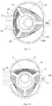
- the housing is provided with a gas inlet 12, an exhaust port 14, and a gas outlet 16 that discharges the separated gas.
- the rotor 2 is provided inside the housing 1 and can rotate; the rotor 2 is provided with three contact ends maintaining a non-stop sliding contact with the inner surface 10 of the housing; the rotor 2 and the inner surface 10 of the housing form individual cavities, i.e., air cavities between adjacent contact ends, and the gas cavities rotate together with the rotor 2 to sequentially pass through the gas inlet 12, the gas outlet 16 and the exhaust port 14.
- the adsorption chambers 32, 34 and 36 are provided inside the rotor 2 to serve as a part of the rotor and can rotate together with the rotor, wherein each adsorption chamber is provided with screen openings in communication with the air cavities, and the interior of each adsorption chamber is loaded with molecular sieves respectively.
- the housing is provided with one gas outlet 16, one gas inlet 12, and one exhaust port 14, wherein the gas inlet 12 and the exhaust port 14 are provided on the left side of the housing 1, and the gas outlet 16 is provided on the right side of the housing 1.
- a pressure relief valve 160 is provided at the gas outlet 16.
- the rotor 2 is provided with three contact ends labeled as contact ends 21, 23 and 25 respectively, and three adsorption chambers, labeled as adsorption chambers 32, 34 and 36 respectively, are separated by the three contact ends.
- the center of the rotor 2 is not coincident with the center of the housing 1, and the center of the rotor 2 rotates around the center of the housing 1 during the rotor 2 rotation.
- the housing 1 is provided with an external gear 100 at the center thereof
- the rotor 2 is provided with an internal gear 200 at the center thereof, wherein the external gear 100 is meshed with the internal gear 200, and the external gear 100 has fewer teeth than the internal gear 200.
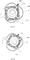
- the operating process of the pressure swing adsorption device of the present invention is as follows: Referring to FIG. 1-1 which shows an initial phase, the contact end 21 of the rotor 2 is at the clockwise side of the gas inlet 12, and the contact end 25 is at the counterclockwise side of the exhaust port 14; that is, the air cavity formed by the adsorption chamber 36, the contact ends 21 and 25 and the inner surface 10 of the housing A is in an intake process of a new phase and an exhaust process of the last phase; the rotation of the internal gear 200 and the external gear 100 drives the rotor 2 to rotate clockwise, and after the contact end 25 moves clockwise beyond the exhaust port 14, the air cavity A begins to enter into an intake state completely. During this process, the volume of the air cavity A gradually increases.
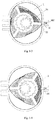
- FIG. 1-2 which shows the maximum volume of air cavity A phase
- FIG. 1-3 which shows the compression process and exhaust preparation phase; the contact end 21 slides to the gas outlet 16, and as the rotor 2 continuously rotates clockwise, the volume of the air cavity A further decreases and is continuously compressed by the air cavity A, such that the gas pressure in the air cavity A gradually increases; and when the pressure is higher than the adsorption pressure of the molecular sieves, the molecular sieves begin to adsorb the corresponding gas.
- the pressure relief valve 160 is opened, and the gas in the air cavity A not being adsorbed by the adsorption chamber begins to exit through the gas outlet.
- FIG. 1-4 which shows the minimum volume of air cavity A phase; as the rotor 2 continuously rotates clockwise, the volume of the air cavity A gradually decreases; in this phase, the volume of the air cavity A reaches the minimum, and the gas outlet 16 exhausts the gas continuously.
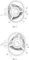
- FIG. 1-5 which shows the exhaust preparation phase
- the contact end 25 slowly approaches the gas outlet 16, the volume of the air cavity A gradually increases, and the gas pressure in the air cavity A gradually decreases; when the gas pressure in the air cavity A is lower than the threshold value of the pressure relief valve 160, the pressure relief valve 160 begins to close.
- the gas pressure in the air cavity A continuously decreases, and when the gas pressure in the air cavity A is lower than the desorption pressure of the molecular sieves, the molecular sieves begin to desorb the gas.
- the adsorbed gas within the adsorption chamber 36 begins to enter into the air cavity A; the contact end 21 slides to the counterclockwise side of the exhaust port 14, and the air cavity A enters the exhaust preparation phase.
- the contact end 21 moves beyond the exhaust port 14, and the contact end 25 slides over the gas outlet 16; the air cavity A is filled with gas desorbed by the adsorption chamber 36, and the air cavity A completely enters the gas exhausting phase.
- Embodiment 2 a working cycle process of an air cavity and a corresponding adsorption chamber is completed.
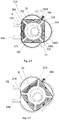
- FIGS. 2-1 to 2-8 are structural schematic drawings of the pressure swing adsorption device of the present invention.
- the rotor 20 is provided inside the housing 110 and can rotate.
- the rotor 20 is provided with four contact ends that maintains a non-stop sliding contact with the inner surface 130 of the housing; the rotor 20 and the inner surface 130 of the housing form individual cavities, i.e., air cavities between adjacent contact ends, and the air cavities rotate together with the rotor 20 to sequentially pass through the gas inlet 120, the gas outlet 180, the first exhaust port 150, and the second exhaust port 140.
- the adsorption chambers 320, 340, 360 and 380 are provided inside the rotor 20 to serve as a part of the rotor 20 and can rotate together with the rotor 20; each adsorption chamber is provided with sieve openings in communication with the air cavities, and the interior of each adsorption chamber is loaded with molecular sieves respectively.
- the housing 110 is provided with a gas outlet 180, a gas inlet 120, a second exhaust port 140, and a first exhaust port 150; the gas inlet 120 and the second exhaust port 140 are provided on the left side of the housing 110, and the gas outlet 180 and the first exhaust port 150 are provided on the right side of the housing 110.
- a pressure relief valve 1800 is provided at the gas outlet 180.
- the rotor 20 is provided with four contact ends labeled as contact ends 210, 230, 250 and 270 respectively, and four adsorption chambers, labeled as adsorption chambers 320, 340 360, and 380 respectively, are separated by the four contact ends.
- the center of the rotor 20 is not coincident with the center of the housing 110, and the center of the rotor 20 rotates around the center of the housing during the rotation of the rotor 2. More specifically, the housing 110 is provided with an external gear 1000 at the center thereof, and the rotor 20 is provided with an internal gear 2000 at the center thereof; the external gear 1000 is meshed with the internal gear 2000, and the external gear 1000 has fewer teeth of the internal gear 2000.
- the operating process of the pressure swing adsorption device of the present invention is as follows:
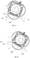
- the contact end 210 of the rotor 20 is on the clockwise side of the gas inlet 120, and the contact end 270 is on the counterclockwise side of the second exhaust port 140; that is, the air cavity B formed by the adsorption chamber 380, the contact ends 210 and 270, and the inner surface 130 of the housing is in an intake process of a new phase and an exhaust process of the last phase; the rotation of the internal gear 2000 and the external gear 1000 drives the rotor 20 to rotate clockwise, and in this process, the volume of the air cavity B gradually increases.
- FIG. 2 which shows the continuous gas intaking and exhaust preparation phase.
- the air cavity B completely enters into an intake state with the volume thereof gradually increasing, and the contact end 210 slides to the right side near the gas outlet 180.
- the volume of the air cavity B will gradually decrease.
- FIG. 2-3 which shows the compression process and gas exhausting start phase.
- the air cavity B continuously compresses the volume thereof, and as the volume of the air cavity B gradually decreases, the gas pressure in the air cavity B gradually increases; and when the pressure is higher than the adsorption pressure of the molecular sieves, the molecular sieves begin to adsorb corresponding gases.
- the pressure relief valve 1800 is opened, and the gas in the air cavity B not being adsorbed by the adsorption chamber 380 begins to exit through the gas outlet 180.
- FIG. 2-4 which shows the minimum volume of air cavity B phase; as the rotor 20 continuously rotates clockwise, the volume of the air cavity B continuously decreases, and the air cavity B keeps exhausting the gas continuously; in this phase, the volume of the air cavity B reaches the minimum.
- the pressure relief valve 1800 begins to close.
- FIG. 2-5 which shows the exhaust preparation phase
- the contact end 270 slowly approaches the gas outlet 180, and the volume of the air cavity B gradually increases while the gas pressure in the air cavity B gradually decreases; when the gas pressure is lower than the desorption pressure of the molecular sieves, the molecular sieves begin to desorb the gas.
- the gas adsorbed in the adsorption chamber 380 begins to enter into the air cavity B; the contact end 210 slides to the right side of the first exhaust port 150, and the air cavity B enters into the first exhaust preparation phase.
- FIG. 2-6 which shows the first exhaust phase; as the rotor continuously rotates clockwise, the contact end 210 begins to slide over the first exhaust port 150, and the air cavity B is filled with gas desorbed by the adsorption chamber 380; the air cavity B enters into the first exhaust phase.
- FIG. 2-7 which shows the double exhaust phase.
- the contact end 270 does not completely slide over the first exhaust port 150, and the contact end 210 slides over the second exhaust port 140; the adsorption chamber 380 keeps exhausting the adsorbed gas, and the second exhaust has already started when the first exhaust is not finished; Meanwhile, the gas is exhausted from the first exhaust port 150 and the second exhaust port 140 simultaneously.
- FIG. 2-8 which shows the complete exhaust phase.
- the contact end 270 completely slides over the first exhaust port 150, and the contact end 210 also moves beyond the second exhaust port 140. Meanwhile, there is still some gas released from the adsorption chamber 380 existing in the air cavity B, and the remaining gas is exhausted by the second exhaust port 140.
Landscapes
- Chemical & Material Sciences (AREA)
- Engineering & Computer Science (AREA)
- Analytical Chemistry (AREA)
- General Chemical & Material Sciences (AREA)
- Oil, Petroleum & Natural Gas (AREA)
- Chemical Kinetics & Catalysis (AREA)
- Separation Of Gases By Adsorption (AREA)
Claims (4)
- Druckwechseladsorptionsvorrichtung, Folgendes umfassend:ein Gehäuse (1) mit einer bogenförmigen Innenoberfläche (10), wobei das Gehäuse mit mindestens einem Gaseinlass (12), mindestens einer Auslassöffnung (14) und mindestens einem Gasauslass (16), der zum Ablassen von getrenntem Gas verwendet wird, versehen ist;einen Rotor (2), der zur exzentrischen Drehung innerhalb des Gehäuses gelagert ist, wobei der Rotor mit mindestens zwei Kontaktenden (21, 23, 25) versehen ist und die Innenoberfläche (10) des Gehäuses derart geformt ist, dass die Kontaktenden einen ununterbrochenen Gleitkontakt mit der Innenoberfläche (10) des Gehäuses aufrechterhalten, wobei eine Außenoberfläche des Rotors und die Innenoberfläche des Gehäuses mindestens zwei einzelne Hohlräume (A) zwischen jeweiligen benachbarten Paaren von Kontaktenden (21, 23; 23, 25; 25, 21) ausbilden und benachbarte Lufthohlräume durch jeweilige Kontaktenden getrennt sind; unddadurch gekennzeichnet, dass sie ferner Folgendes umfasst: mindestens zwei Adsorptionskammern (32, 34, 36), die jeweils einem jeweiligen Hohlraum (A) entsprechen und mit jeweiligen Trennwandöffnungen zur Verbindung damit versehen sind, wobei die Adsorptionskammern (32, 34, 36) innerhalb des Rotors (2) bereitgestellt sind, als ein Teil des Rotors dienen und sich zusammen mit dem Rotor drehen, wobei die Innenräume der Adsorptionskammern mit Molekularsieben beladen sind und wobei ein Druckentlastungsventil (160) an dem Gasauslass (16) bereitgestellt ist, wobei die Anordnung derart ist, dass, wenn der Rotor gedreht wird, die einzelnen Hohlräume (A) sich mit dem Rotor (2) drehen, um in jedem Arbeitszyklus nacheinander den Gaseinlass (12), den Gasauslass (16) und die Auslassöffnung (14) zu passieren.
- Druckwechseladsorptionsvorrichtung nach Anspruch 1, wobei die Druckwechseladsorptionsvorrichtung ferner eine zentrale Welle mit einem Außenzahnrad (100) umfasst, die sich in der Mitte des Gehäuses befindet und von einem Motor angetrieben wird, um sich zu drehen, wobei in der Mitte des Rotors (2) ein Innenzahnrad (200) bereitgestellt ist, wobei das Außenzahnrad der zentralen Welle mit dem Innenzahnrad des Rotors in Eingriff steht und das Außenzahnrad weniger Zähne als das Innenzahnrad aufweist.
- Druckwechseladsorptionsvorrichtung nach Anspruch 1, wobei:der Rotor mit einem ersten, zweiten und dritten Kontaktende (21, 23, 25) versehen ist, die im Uhrzeigersinn angeordnet sind und einen ununterbrochenen Gleitkontakt mit der Innenoberfläche (10) des Gehäuses aufrechterhalten;drei Luftkammern zwischen der Außenoberfläche des Rotors und der Innenoberfläche des Gehäuses ausgebildet sind und eine erste, zweite und dritte Adsorptionskammer, die jeweils den drei Luftkammern entsprechen, innerhalb des Rotors bereitgestellt sind;wobei die erste Adsorptionskammer sich zwischen dem ersten Kontaktende (21) und dem zweiten Kontaktende (23) befindet, die zweite Adsorptionskammer sich zwischen dem zweiten Kontaktende (23) und dem dritten Kontaktende (25) befindet und die dritte Adsorptionskammer sich zwischen dem dritten Kontaktende (25) und dem ersten Kontaktende (21) befindet;das Gehäuse mit einem Gasauslass (16), einem Gaseinlass (12) und einer Auslassöffnung (14) versehen ist und der Gaseinlass (12) sich bezogen auf die Auslassöffnung (14) an einer im Uhrzeigersinn gelegenen Position derart befindet;dass, wenn die Vorrichtung sich in einer Ausgangsstellung befindet (Fig. 1-1):das erste Kontaktende (21) des Rotors (2) sich auf einer im Uhrzeigersinn gelegenen Seite des Gaseinlasses (12) befindet und das dritte Kontaktende (25) sich auf einer entgegen dem Uhrzeigersinn gelegenen Seite der Auslassöffnung (14) befindet, wobei der Gaseinlass (12) und die Auslassöffnung (14) sich zwischen dem ersten Kontaktende (21) und dem dritten Kontaktende (25) befinden; undder Gasauslass (16) direkt dem zweiten Kontaktende (23) zugewandt ist.
- Druckwechseladsorptionsvorrichtung nach Anspruch 1, wobei der Rotor (20) mit einem ersten, zweiten, dritten und vierten Kontaktende (210, 230, 250, 270) versehen ist, die im Uhrzeigersinn angeordnet sind und einen ununterbrochenen Gleitkontakt mit der Innenoberfläche (100) des Gehäuses (10) aufrechterhalten:
vier Luftkammern zwischen der Außenoberfläche des Rotors (20) und der Innenoberfläche (100) des Gehäuses ausgebildet sind und eine erste, zweite, dritte und vierte Adsorptionskammer, die jeweils den vier Luftkammern entsprechen, innerhalb des Rotors bereitgestellt sind:wobei die erste Adsorptionskammer sich zwischen dem ersten Kontaktende und dem zweiten Kontaktende befindet, die zweite Adsorptionskammer sich zwischen dem zweiten Kontaktende und dem dritten Kontaktende befindet, die dritte Adsorptionskammer sich zwischen dem dritten Kontaktende und dem vierten Kontaktende befindet und die vierte Adsorptionskammer sich zwischen dem vierten Kontaktende und dem ersten Kontaktende befindet;das Gehäuse mit einem Gasauslass (180), einem Gaseinlass (120), einer ersten Auslassöffnung (160) und einer zweiten Auslassöffnung (140) versehen ist und der Gaseinlass (120) sich bezogen auf die zweite Auslassöffnung (140) an einer im Uhrzeigersinn gelegenen Position derart befindet;dass, wenn die Vorrichtung sich in einer Ausgangsstellung befindet (Fig. 2-1)das erste Kontaktende (210) des Rotors sich auf der im Uhrzeigersinn gelegenen Seite des Gaseinlasses (120) befindet und das vierte Kontaktende (270) sich auf der entgegen dem Uhrzeigersinn gelegenen Seite der zweiten Auslassöffnung (140) befindet, wobei der Gaseinlass (120) und die zweite Auslassöffnung (140) sich zwischen dem ersten Kontaktende (210) und dem vierten Kontaktende (270) befinden;die erste Auslassöffnung (160) sich zwischen dem dritten Kontaktende (250) und dem vierten Kontaktende (270) befindet und der Gasauslass (180) sich zwischen dem ersten Kontaktende (210) und dem zweiten Kontaktende (230) befindet und dem zweiten Kontaktende (230) benachbart ist.
Applications Claiming Priority (2)
| Application Number | Priority Date | Filing Date | Title |
|---|---|---|---|
| CN201310413453.2A CN103432863B (zh) | 2013-09-10 | 2013-09-10 | 变压吸附装置 |
| PCT/CN2013/086595 WO2015035694A1 (zh) | 2013-09-10 | 2013-11-06 | 变压吸附装置 |
Publications (3)
| Publication Number | Publication Date |
|---|---|
| EP3045217A1 EP3045217A1 (de) | 2016-07-20 |
| EP3045217A4 EP3045217A4 (de) | 2017-05-03 |
| EP3045217B1 true EP3045217B1 (de) | 2020-01-01 |
Family
ID=49686634
Family Applications (1)
| Application Number | Title | Priority Date | Filing Date |
|---|---|---|---|
| EP13893669.5A Active EP3045217B1 (de) | 2013-09-10 | 2013-11-06 | Druckwechseladsorptionsvorrichtung |
Country Status (9)
| Country | Link |
|---|---|
| US (1) | US9731242B2 (de) |
| EP (1) | EP3045217B1 (de) |
| CN (1) | CN103432863B (de) |
| AU (1) | AU2013400510B2 (de) |
| NZ (1) | NZ718875A (de) |
| PH (1) | PH12016500646A1 (de) |
| SG (1) | SG11201602768PA (de) |
| TW (1) | TW201515689A (de) |
| WO (1) | WO2015035694A1 (de) |
Families Citing this family (2)
| Publication number | Priority date | Publication date | Assignee | Title |
|---|---|---|---|---|
| RU2628393C1 (ru) * | 2016-03-02 | 2017-08-16 | Общество с ограниченной ответственностью "ТамбовСорбТех" | Роторно-пластинчатая адсорбционная установка |
| CN116440654B (zh) * | 2023-03-13 | 2023-11-21 | 河北红光燃料有限责任公司 | 一种燃煤烟气脱硫脱硝脱碳设备 |
Family Cites Families (11)
| Publication number | Priority date | Publication date | Assignee | Title |
|---|---|---|---|---|
| JPS49128113A (de) * | 1973-04-17 | 1974-12-07 | ||
| DE3001525A1 (de) * | 1980-01-17 | 1981-07-23 | Adolf Dipl.-Ing. 3060 Stadthagen Margraf | Vorrichtung zum stoffaustausch in einer wirbelschichtkammer |
| US5169414A (en) * | 1990-07-03 | 1992-12-08 | Flakt, Inc. | Rotary adsorption assembly |
| AU752114B2 (en) * | 1997-12-01 | 2002-09-05 | Air Products And Chemicals, Inc. | Modular pressure swing adsorption apparatus |
| AU770022B2 (en) * | 1998-12-16 | 2004-02-12 | Questair Technologies, Inc. | Gas separation with split stream centrifugal turbomachinery |
| US6517610B1 (en) * | 2001-11-13 | 2003-02-11 | The United States Of America As Represented By The Secretary Of The Navy | Microelectromechanical gas concentrator |
| JP4739662B2 (ja) * | 2003-09-09 | 2011-08-03 | 帝人株式会社 | 酸素濃縮機 |
| JP2007237004A (ja) * | 2006-02-09 | 2007-09-20 | Terumo Corp | ガス濃縮装置およびその制御方法 |
| US20080226480A1 (en) * | 2007-03-15 | 2008-09-18 | Ion Metrics, Inc. | Multi-Stage Trochoidal Vacuum Pump |
| CN102755810A (zh) * | 2012-08-02 | 2012-10-31 | 南京圣火水泥新技术工程有限公司 | 转子式变压吸附气体分离装置 |
| CN203507775U (zh) * | 2013-09-10 | 2014-04-02 | 周小山 | 变压吸附装置 |
-
2013
- 2013-09-10 CN CN201310413453.2A patent/CN103432863B/zh active Active
- 2013-11-06 WO PCT/CN2013/086595 patent/WO2015035694A1/zh not_active Ceased
- 2013-11-06 SG SG11201602768PA patent/SG11201602768PA/en unknown
- 2013-11-06 NZ NZ718875A patent/NZ718875A/en unknown
- 2013-11-06 EP EP13893669.5A patent/EP3045217B1/de active Active
- 2013-11-06 US US15/028,478 patent/US9731242B2/en active Active
- 2013-11-06 AU AU2013400510A patent/AU2013400510B2/en active Active
-
2014
- 2014-08-29 TW TW103129973A patent/TW201515689A/zh unknown
-
2016
- 2016-04-08 PH PH12016500646A patent/PH12016500646A1/en unknown
Non-Patent Citations (1)
| Title |
|---|
| None * |
Also Published As
| Publication number | Publication date |
|---|---|
| WO2015035694A1 (zh) | 2015-03-19 |
| AU2013400510A1 (en) | 2016-05-05 |
| SG11201602768PA (en) | 2016-05-30 |
| PH12016500646B1 (en) | 2016-05-30 |
| EP3045217A4 (de) | 2017-05-03 |
| CN103432863B (zh) | 2015-03-11 |
| US20160279559A1 (en) | 2016-09-29 |
| PH12016500646A1 (en) | 2016-05-30 |
| EP3045217A1 (de) | 2016-07-20 |
| NZ718875A (en) | 2016-11-25 |
| US9731242B2 (en) | 2017-08-15 |
| CN103432863A (zh) | 2013-12-11 |
| AU2013400510B2 (en) | 2017-04-27 |
| TW201515689A (zh) | 2015-05-01 |
Similar Documents
| Publication | Publication Date | Title |
|---|---|---|
| US6514319B2 (en) | Life support oxygen concentrator | |
| US7250073B2 (en) | Life support oxygen concentrator | |
| CA2320551C (en) | Compact pressure swing adsorption apparatus | |
| CN104471251A (zh) | 气体压缩机 | |
| EP3045217B1 (de) | Druckwechseladsorptionsvorrichtung | |
| US10260346B2 (en) | Circulating piston engine having a rotary valve assembly | |
| EP2920469A2 (de) | Vorrichtung und verfahren zur verbesserung der verdichtereffizienz | |
| CN202001299U (zh) | 旋转空气压缩机 | |
| JP2005083516A (ja) | 回転バルブおよび圧力スイング吸着式気体分離装置 | |
| CN106762642A (zh) | 旋转压缩机 | |
| CN203507775U (zh) | 变压吸附装置 | |
| JPH07301185A (ja) | スクロール装置 | |
| US7162993B2 (en) | Intersecting vane machines | |
| CN103233782A (zh) | 旋塞式旋转压缩膨胀机构 | |
| RU2436971C1 (ru) | Шестеренчатый двигатель внутреннего сгорания | |
| JPH1111906A (ja) | オルダム式コンプレッサー使用の酸素濃縮装置 | |
| CN206221253U (zh) | 旋转压缩机 | |
| JP4064079B2 (ja) | 医療用酸素濃縮器 | |
| CN120946573A (zh) | 滑片式真空压缩一体机、真空变压吸附制氧系统及方法 | |
| KR101155035B1 (ko) | 회전클랩 흡압장치 | |
| CA2393277A1 (en) | Life support oxygen concentrator | |
| RU2628393C1 (ru) | Роторно-пластинчатая адсорбционная установка | |
| CN103696961A (zh) | 一种双转子相向旋转压缩机 | |
| JP2022152234A (ja) | 内燃機関のco2分離装置 | |
| CN204941692U (zh) | 增压发动机转速主导型容积调节系统 |
Legal Events
| Date | Code | Title | Description |
|---|---|---|---|
| PUAI | Public reference made under article 153(3) epc to a published international application that has entered the european phase |
Free format text: ORIGINAL CODE: 0009012 |
|
| 17P | Request for examination filed |
Effective date: 20160422 |
|
| AK | Designated contracting states |
Kind code of ref document: A1 Designated state(s): AL AT BE BG CH CY CZ DE DK EE ES FI FR GB GR HR HU IE IS IT LI LT LU LV MC MK MT NL NO PL PT RO RS SE SI SK SM TR |
|
| AX | Request for extension of the european patent |
Extension state: BA ME |
|
| RAP1 | Party data changed (applicant data changed or rights of an application transferred) |
Owner name: LEI, JI Owner name: ZHOU, XIAOSHAN Owner name: SUN, MING |
|
| RIN1 | Information on inventor provided before grant (corrected) |
Inventor name: SUN, MING Inventor name: ZHOU, XIAOSHAN Inventor name: LEI, JI |
|
| DAX | Request for extension of the european patent (deleted) | ||
| A4 | Supplementary search report drawn up and despatched |
Effective date: 20170404 |
|
| RIC1 | Information provided on ipc code assigned before grant |
Ipc: B01D 53/06 20060101ALI20170327BHEP Ipc: B01D 53/047 20060101AFI20170327BHEP |
|
| RAP1 | Party data changed (applicant data changed or rights of an application transferred) |
Owner name: IP TECH PTE. LTD. |
|
| RIN1 | Information on inventor provided before grant (corrected) |
Inventor name: ZHOU, XIAOSHAN Inventor name: LEI, JI Inventor name: SUN, MING |
|
| STAA | Information on the status of an ep patent application or granted ep patent |
Free format text: STATUS: EXAMINATION IS IN PROGRESS |
|
| 17Q | First examination report despatched |
Effective date: 20190218 |
|
| GRAP | Despatch of communication of intention to grant a patent |
Free format text: ORIGINAL CODE: EPIDOSNIGR1 |
|
| STAA | Information on the status of an ep patent application or granted ep patent |
Free format text: STATUS: GRANT OF PATENT IS INTENDED |
|
| INTG | Intention to grant announced |
Effective date: 20190531 |
|
| GRAS | Grant fee paid |
Free format text: ORIGINAL CODE: EPIDOSNIGR3 |
|
| GRAA | (expected) grant |
Free format text: ORIGINAL CODE: 0009210 |
|
| STAA | Information on the status of an ep patent application or granted ep patent |
Free format text: STATUS: THE PATENT HAS BEEN GRANTED |
|
| AK | Designated contracting states |
Kind code of ref document: B1 Designated state(s): AL AT BE BG CH CY CZ DE DK EE ES FI FR GB GR HR HU IE IS IT LI LT LU LV MC MK MT NL NO PL PT RO RS SE SI SK SM TR |
|
| REG | Reference to a national code |
Ref country code: GB Ref legal event code: FG4D |
|
| REG | Reference to a national code |
Ref country code: CH Ref legal event code: EP Ref country code: AT Ref legal event code: REF Ref document number: 1219062 Country of ref document: AT Kind code of ref document: T Effective date: 20200115 |
|
| REG | Reference to a national code |
Ref country code: IE Ref legal event code: FG4D |
|
| REG | Reference to a national code |
Ref country code: DE Ref legal event code: R096 Ref document number: 602013064743 Country of ref document: DE |
|
| REG | Reference to a national code |
Ref country code: NL Ref legal event code: MP Effective date: 20200101 |
|
| REG | Reference to a national code |
Ref country code: LT Ref legal event code: MG4D |
|
| PG25 | Lapsed in a contracting state [announced via postgrant information from national office to epo] |
Ref country code: CZ Free format text: LAPSE BECAUSE OF FAILURE TO SUBMIT A TRANSLATION OF THE DESCRIPTION OR TO PAY THE FEE WITHIN THE PRESCRIBED TIME-LIMIT Effective date: 20200101 Ref country code: FI Free format text: LAPSE BECAUSE OF FAILURE TO SUBMIT A TRANSLATION OF THE DESCRIPTION OR TO PAY THE FEE WITHIN THE PRESCRIBED TIME-LIMIT Effective date: 20200101 Ref country code: NO Free format text: LAPSE BECAUSE OF FAILURE TO SUBMIT A TRANSLATION OF THE DESCRIPTION OR TO PAY THE FEE WITHIN THE PRESCRIBED TIME-LIMIT Effective date: 20200401 Ref country code: RS Free format text: LAPSE BECAUSE OF FAILURE TO SUBMIT A TRANSLATION OF THE DESCRIPTION OR TO PAY THE FEE WITHIN THE PRESCRIBED TIME-LIMIT Effective date: 20200101 Ref country code: LT Free format text: LAPSE BECAUSE OF FAILURE TO SUBMIT A TRANSLATION OF THE DESCRIPTION OR TO PAY THE FEE WITHIN THE PRESCRIBED TIME-LIMIT Effective date: 20200101 Ref country code: PT Free format text: LAPSE BECAUSE OF FAILURE TO SUBMIT A TRANSLATION OF THE DESCRIPTION OR TO PAY THE FEE WITHIN THE PRESCRIBED TIME-LIMIT Effective date: 20200527 Ref country code: NL Free format text: LAPSE BECAUSE OF FAILURE TO SUBMIT A TRANSLATION OF THE DESCRIPTION OR TO PAY THE FEE WITHIN THE PRESCRIBED TIME-LIMIT Effective date: 20200101 |
|
| PG25 | Lapsed in a contracting state [announced via postgrant information from national office to epo] |
Ref country code: IS Free format text: LAPSE BECAUSE OF FAILURE TO SUBMIT A TRANSLATION OF THE DESCRIPTION OR TO PAY THE FEE WITHIN THE PRESCRIBED TIME-LIMIT Effective date: 20200501 Ref country code: BG Free format text: LAPSE BECAUSE OF FAILURE TO SUBMIT A TRANSLATION OF THE DESCRIPTION OR TO PAY THE FEE WITHIN THE PRESCRIBED TIME-LIMIT Effective date: 20200401 Ref country code: GR Free format text: LAPSE BECAUSE OF FAILURE TO SUBMIT A TRANSLATION OF THE DESCRIPTION OR TO PAY THE FEE WITHIN THE PRESCRIBED TIME-LIMIT Effective date: 20200402 Ref country code: SE Free format text: LAPSE BECAUSE OF FAILURE TO SUBMIT A TRANSLATION OF THE DESCRIPTION OR TO PAY THE FEE WITHIN THE PRESCRIBED TIME-LIMIT Effective date: 20200101 Ref country code: LV Free format text: LAPSE BECAUSE OF FAILURE TO SUBMIT A TRANSLATION OF THE DESCRIPTION OR TO PAY THE FEE WITHIN THE PRESCRIBED TIME-LIMIT Effective date: 20200101 Ref country code: HR Free format text: LAPSE BECAUSE OF FAILURE TO SUBMIT A TRANSLATION OF THE DESCRIPTION OR TO PAY THE FEE WITHIN THE PRESCRIBED TIME-LIMIT Effective date: 20200101 |
|
| REG | Reference to a national code |
Ref country code: DE Ref legal event code: R097 Ref document number: 602013064743 Country of ref document: DE |
|
| PG25 | Lapsed in a contracting state [announced via postgrant information from national office to epo] |
Ref country code: ES Free format text: LAPSE BECAUSE OF FAILURE TO SUBMIT A TRANSLATION OF THE DESCRIPTION OR TO PAY THE FEE WITHIN THE PRESCRIBED TIME-LIMIT Effective date: 20200101 Ref country code: RO Free format text: LAPSE BECAUSE OF FAILURE TO SUBMIT A TRANSLATION OF THE DESCRIPTION OR TO PAY THE FEE WITHIN THE PRESCRIBED TIME-LIMIT Effective date: 20200101 Ref country code: SK Free format text: LAPSE BECAUSE OF FAILURE TO SUBMIT A TRANSLATION OF THE DESCRIPTION OR TO PAY THE FEE WITHIN THE PRESCRIBED TIME-LIMIT Effective date: 20200101 Ref country code: EE Free format text: LAPSE BECAUSE OF FAILURE TO SUBMIT A TRANSLATION OF THE DESCRIPTION OR TO PAY THE FEE WITHIN THE PRESCRIBED TIME-LIMIT Effective date: 20200101 Ref country code: DK Free format text: LAPSE BECAUSE OF FAILURE TO SUBMIT A TRANSLATION OF THE DESCRIPTION OR TO PAY THE FEE WITHIN THE PRESCRIBED TIME-LIMIT Effective date: 20200101 Ref country code: SM Free format text: LAPSE BECAUSE OF FAILURE TO SUBMIT A TRANSLATION OF THE DESCRIPTION OR TO PAY THE FEE WITHIN THE PRESCRIBED TIME-LIMIT Effective date: 20200101 |
|
| PLBE | No opposition filed within time limit |
Free format text: ORIGINAL CODE: 0009261 |
|
| STAA | Information on the status of an ep patent application or granted ep patent |
Free format text: STATUS: NO OPPOSITION FILED WITHIN TIME LIMIT |
|
| REG | Reference to a national code |
Ref country code: AT Ref legal event code: MK05 Ref document number: 1219062 Country of ref document: AT Kind code of ref document: T Effective date: 20200101 |
|
| 26N | No opposition filed |
Effective date: 20201002 |
|
| PG25 | Lapsed in a contracting state [announced via postgrant information from national office to epo] |
Ref country code: IT Free format text: LAPSE BECAUSE OF FAILURE TO SUBMIT A TRANSLATION OF THE DESCRIPTION OR TO PAY THE FEE WITHIN THE PRESCRIBED TIME-LIMIT Effective date: 20200101 Ref country code: AT Free format text: LAPSE BECAUSE OF FAILURE TO SUBMIT A TRANSLATION OF THE DESCRIPTION OR TO PAY THE FEE WITHIN THE PRESCRIBED TIME-LIMIT Effective date: 20200101 |
|
| PG25 | Lapsed in a contracting state [announced via postgrant information from national office to epo] |
Ref country code: SI Free format text: LAPSE BECAUSE OF FAILURE TO SUBMIT A TRANSLATION OF THE DESCRIPTION OR TO PAY THE FEE WITHIN THE PRESCRIBED TIME-LIMIT Effective date: 20200101 Ref country code: PL Free format text: LAPSE BECAUSE OF FAILURE TO SUBMIT A TRANSLATION OF THE DESCRIPTION OR TO PAY THE FEE WITHIN THE PRESCRIBED TIME-LIMIT Effective date: 20200101 |
|
| PG25 | Lapsed in a contracting state [announced via postgrant information from national office to epo] |
Ref country code: MC Free format text: LAPSE BECAUSE OF FAILURE TO SUBMIT A TRANSLATION OF THE DESCRIPTION OR TO PAY THE FEE WITHIN THE PRESCRIBED TIME-LIMIT Effective date: 20200101 |
|
| REG | Reference to a national code |
Ref country code: CH Ref legal event code: PL |
|
| PG25 | Lapsed in a contracting state [announced via postgrant information from national office to epo] |
Ref country code: LU Free format text: LAPSE BECAUSE OF NON-PAYMENT OF DUE FEES Effective date: 20201106 |
|
| REG | Reference to a national code |
Ref country code: BE Ref legal event code: MM Effective date: 20201130 |
|
| PG25 | Lapsed in a contracting state [announced via postgrant information from national office to epo] |
Ref country code: LI Free format text: LAPSE BECAUSE OF NON-PAYMENT OF DUE FEES Effective date: 20201130 Ref country code: CH Free format text: LAPSE BECAUSE OF NON-PAYMENT OF DUE FEES Effective date: 20201130 |
|
| PG25 | Lapsed in a contracting state [announced via postgrant information from national office to epo] |
Ref country code: IE Free format text: LAPSE BECAUSE OF NON-PAYMENT OF DUE FEES Effective date: 20201106 |
|
| PG25 | Lapsed in a contracting state [announced via postgrant information from national office to epo] |
Ref country code: TR Free format text: LAPSE BECAUSE OF FAILURE TO SUBMIT A TRANSLATION OF THE DESCRIPTION OR TO PAY THE FEE WITHIN THE PRESCRIBED TIME-LIMIT Effective date: 20200101 Ref country code: MT Free format text: LAPSE BECAUSE OF FAILURE TO SUBMIT A TRANSLATION OF THE DESCRIPTION OR TO PAY THE FEE WITHIN THE PRESCRIBED TIME-LIMIT Effective date: 20200101 Ref country code: CY Free format text: LAPSE BECAUSE OF FAILURE TO SUBMIT A TRANSLATION OF THE DESCRIPTION OR TO PAY THE FEE WITHIN THE PRESCRIBED TIME-LIMIT Effective date: 20200101 |
|
| PG25 | Lapsed in a contracting state [announced via postgrant information from national office to epo] |
Ref country code: MK Free format text: LAPSE BECAUSE OF FAILURE TO SUBMIT A TRANSLATION OF THE DESCRIPTION OR TO PAY THE FEE WITHIN THE PRESCRIBED TIME-LIMIT Effective date: 20200101 Ref country code: AL Free format text: LAPSE BECAUSE OF FAILURE TO SUBMIT A TRANSLATION OF THE DESCRIPTION OR TO PAY THE FEE WITHIN THE PRESCRIBED TIME-LIMIT Effective date: 20200101 |
|
| PG25 | Lapsed in a contracting state [announced via postgrant information from national office to epo] |
Ref country code: BE Free format text: LAPSE BECAUSE OF NON-PAYMENT OF DUE FEES Effective date: 20201130 |
|
| P01 | Opt-out of the competence of the unified patent court (upc) registered |
Effective date: 20230515 |
|
| REG | Reference to a national code |
Ref country code: DE Ref legal event code: R081 Ref document number: 602013064743 Country of ref document: DE Owner name: ADVATE TECH PTE. LTD., SG Free format text: FORMER OWNER: IP TECH PTE. LTD., SINGAPORE, SG |
|
| REG | Reference to a national code |
Ref country code: GB Ref legal event code: 732E Free format text: REGISTERED BETWEEN 20251023 AND 20251029 |
|
| PGFP | Annual fee paid to national office [announced via postgrant information from national office to epo] |
Ref country code: DE Payment date: 20251022 Year of fee payment: 13 |
|
| PGFP | Annual fee paid to national office [announced via postgrant information from national office to epo] |
Ref country code: GB Payment date: 20251023 Year of fee payment: 13 |
|
| PGFP | Annual fee paid to national office [announced via postgrant information from national office to epo] |
Ref country code: FR Payment date: 20251023 Year of fee payment: 13 |