EP3044397B1 - Procédé pour commander un actionneur électrique d'une porte ou vantail de porte et dispositif de commande de porte - Google Patents
Procédé pour commander un actionneur électrique d'une porte ou vantail de porte et dispositif de commande de porte Download PDFInfo
- Publication number
- EP3044397B1 EP3044397B1 EP14796463.9A EP14796463A EP3044397B1 EP 3044397 B1 EP3044397 B1 EP 3044397B1 EP 14796463 A EP14796463 A EP 14796463A EP 3044397 B1 EP3044397 B1 EP 3044397B1
- Authority
- EP
- European Patent Office
- Prior art keywords
- door
- travel
- drive
- directions
- wing
- Prior art date
- Legal status (The legal status is an assumption and is not a legal conclusion. Google has not performed a legal analysis and makes no representation as to the accuracy of the status listed.)
- Active
Links
Images

Classifications
-
- E—FIXED CONSTRUCTIONS
- E05—LOCKS; KEYS; WINDOW OR DOOR FITTINGS; SAFES
- E05F—DEVICES FOR MOVING WINGS INTO OPEN OR CLOSED POSITION; CHECKS FOR WINGS; WING FITTINGS NOT OTHERWISE PROVIDED FOR, CONCERNED WITH THE FUNCTIONING OF THE WING
- E05F15/00—Power-operated mechanisms for wings
- E05F15/70—Power-operated mechanisms for wings with automatic actuation
-
- E—FIXED CONSTRUCTIONS
- E05—LOCKS; KEYS; WINDOW OR DOOR FITTINGS; SAFES
- E05F—DEVICES FOR MOVING WINGS INTO OPEN OR CLOSED POSITION; CHECKS FOR WINGS; WING FITTINGS NOT OTHERWISE PROVIDED FOR, CONCERNED WITH THE FUNCTIONING OF THE WING
- E05F15/00—Power-operated mechanisms for wings
- E05F15/60—Power-operated mechanisms for wings using electrical actuators
- E05F15/603—Power-operated mechanisms for wings using electrical actuators using rotary electromotors
- E05F15/632—Power-operated mechanisms for wings using electrical actuators using rotary electromotors for horizontally-sliding wings
-
- E—FIXED CONSTRUCTIONS
- E05—LOCKS; KEYS; WINDOW OR DOOR FITTINGS; SAFES
- E05Y—INDEXING SCHEME ASSOCIATED WITH SUBCLASSES E05D AND E05F, RELATING TO CONSTRUCTION ELEMENTS, ELECTRIC CONTROL, POWER SUPPLY, POWER SIGNAL OR TRANSMISSION, USER INTERFACES, MOUNTING OR COUPLING, DETAILS, ACCESSORIES, AUXILIARY OPERATIONS NOT OTHERWISE PROVIDED FOR, APPLICATION THEREOF
- E05Y2400/00—Electronic control; Electrical power; Power supply; Power or signal transmission; User interfaces
- E05Y2400/10—Electronic control
- E05Y2400/30—Electronic control of motors
- E05Y2400/3013—Electronic control of motors during manual wing operation
- E05Y2400/3015—Power assistance
-
- E—FIXED CONSTRUCTIONS
- E05—LOCKS; KEYS; WINDOW OR DOOR FITTINGS; SAFES
- E05Y—INDEXING SCHEME ASSOCIATED WITH SUBCLASSES E05D AND E05F, RELATING TO CONSTRUCTION ELEMENTS, ELECTRIC CONTROL, POWER SUPPLY, POWER SIGNAL OR TRANSMISSION, USER INTERFACES, MOUNTING OR COUPLING, DETAILS, ACCESSORIES, AUXILIARY OPERATIONS NOT OTHERWISE PROVIDED FOR, APPLICATION THEREOF
- E05Y2400/00—Electronic control; Electrical power; Power supply; Power or signal transmission; User interfaces
- E05Y2400/10—Electronic control
- E05Y2400/30—Electronic control of motors
- E05Y2400/3013—Electronic control of motors during manual wing operation
- E05Y2400/3016—Overriding existing wing movement
-
- E—FIXED CONSTRUCTIONS
- E05—LOCKS; KEYS; WINDOW OR DOOR FITTINGS; SAFES
- E05Y—INDEXING SCHEME ASSOCIATED WITH SUBCLASSES E05D AND E05F, RELATING TO CONSTRUCTION ELEMENTS, ELECTRIC CONTROL, POWER SUPPLY, POWER SIGNAL OR TRANSMISSION, USER INTERFACES, MOUNTING OR COUPLING, DETAILS, ACCESSORIES, AUXILIARY OPERATIONS NOT OTHERWISE PROVIDED FOR, APPLICATION THEREOF
- E05Y2400/00—Electronic control; Electrical power; Power supply; Power or signal transmission; User interfaces
- E05Y2400/10—Electronic control
- E05Y2400/30—Electronic control of motors
- E05Y2400/304—Voltage control
-
- E—FIXED CONSTRUCTIONS
- E05—LOCKS; KEYS; WINDOW OR DOOR FITTINGS; SAFES
- E05Y—INDEXING SCHEME ASSOCIATED WITH SUBCLASSES E05D AND E05F, RELATING TO CONSTRUCTION ELEMENTS, ELECTRIC CONTROL, POWER SUPPLY, POWER SIGNAL OR TRANSMISSION, USER INTERFACES, MOUNTING OR COUPLING, DETAILS, ACCESSORIES, AUXILIARY OPERATIONS NOT OTHERWISE PROVIDED FOR, APPLICATION THEREOF
- E05Y2400/00—Electronic control; Electrical power; Power supply; Power or signal transmission; User interfaces
- E05Y2400/10—Electronic control
- E05Y2400/36—Speed control, detection or monitoring
-
- E—FIXED CONSTRUCTIONS
- E05—LOCKS; KEYS; WINDOW OR DOOR FITTINGS; SAFES
- E05Y—INDEXING SCHEME ASSOCIATED WITH SUBCLASSES E05D AND E05F, RELATING TO CONSTRUCTION ELEMENTS, ELECTRIC CONTROL, POWER SUPPLY, POWER SIGNAL OR TRANSMISSION, USER INTERFACES, MOUNTING OR COUPLING, DETAILS, ACCESSORIES, AUXILIARY OPERATIONS NOT OTHERWISE PROVIDED FOR, APPLICATION THEREOF
- E05Y2400/00—Electronic control; Electrical power; Power supply; Power or signal transmission; User interfaces
- E05Y2400/10—Electronic control
- E05Y2400/44—Sensors not directly associated with the wing movement
-
- E—FIXED CONSTRUCTIONS
- E05—LOCKS; KEYS; WINDOW OR DOOR FITTINGS; SAFES
- E05Y—INDEXING SCHEME ASSOCIATED WITH SUBCLASSES E05D AND E05F, RELATING TO CONSTRUCTION ELEMENTS, ELECTRIC CONTROL, POWER SUPPLY, POWER SIGNAL OR TRANSMISSION, USER INTERFACES, MOUNTING OR COUPLING, DETAILS, ACCESSORIES, AUXILIARY OPERATIONS NOT OTHERWISE PROVIDED FOR, APPLICATION THEREOF
- E05Y2900/00—Application of doors, windows, wings or fittings thereof
- E05Y2900/10—Application of doors, windows, wings or fittings thereof for buildings or parts thereof
- E05Y2900/11—Application of doors, windows, wings or fittings thereof for buildings or parts thereof for industrial buildings
-
- E—FIXED CONSTRUCTIONS
- E05—LOCKS; KEYS; WINDOW OR DOOR FITTINGS; SAFES
- E05Y—INDEXING SCHEME ASSOCIATED WITH SUBCLASSES E05D AND E05F, RELATING TO CONSTRUCTION ELEMENTS, ELECTRIC CONTROL, POWER SUPPLY, POWER SIGNAL OR TRANSMISSION, USER INTERFACES, MOUNTING OR COUPLING, DETAILS, ACCESSORIES, AUXILIARY OPERATIONS NOT OTHERWISE PROVIDED FOR, APPLICATION THEREOF
- E05Y2900/00—Application of doors, windows, wings or fittings thereof
- E05Y2900/10—Application of doors, windows, wings or fittings thereof for buildings or parts thereof
- E05Y2900/13—Type of wing
- E05Y2900/132—Doors
Definitions
- the invention relates to a method for controlling an electric drive of a door or a door leaf according to claim 1 and a door control device according to claim 9.
- Door control devices serve to control and / or regulate at least one electric drive motor for opening or closing at least one door or one door leaf, in particular at least one sliding door or one leaf of a sliding door.
- Sliding doors are mainly found in elevators, on platforms for access control to trains, at the entrance of buildings or for personal protection in an industrial environment, e.g. on machine tools.
- direct current motors or, more recently, electronically commutated, brushless, permanently excited synchronous motors with or without a downstream gear are used as electric drive motors.
- Examples of door drives with such a door control device are in EP 1 894 877 A2 , the DE 10 2011 004 019 A1 and the EP 1 102 390 A2 disclosed.
- Door control devices of this type are increasingly being integrated into an automation system and connected to a central, higher-level controller via an industrial communication link (e.g. PROFIBUS, PROFINET).
- industrial communication link e.g. PROFIBUS, PROFINET
- a door or a door leaf is in a first direction of travel (closing direction) from an open position to a closed position and conversely movable in a second direction of travel (opening direction) from the closed position to the open position.
- first direction of travel closing direction
- second direction of travel open direction
- a so-called "Push & Go" function is already known for revolving doors.
- a short manual pushing of the door in the opening direction i.e. a force acting vertically on a side surface of the door in the direction of rotation of the door
- the revolving doors in and of themselves have little weight and could also be easily opened manually.
- the function is just a convenience function that makes it possible, for example, to open the door when there is little hand freedom.
- a fitting for a sliding door with a stationary fitting part and a fitting part attached to the movable wing of the door and a drive device for the movable fitting part is known, the wing being liftable via the fitting and that the drive device is provided with a programmable control.
- the control can be activated, among other things, by manually pushing the sash, in particular using the handle of the door, or manually pushing the sash in the opening or closing direction.
- a method for controlling a door in particular a motor vehicle door, is known, an electric motor being in operative connection with the door, the electric motor being controlled by a controller when the door is manually operated in such a way that the motor exerts a first force on the door , wherein a system-inherent second force counteracts the manual actuation of the door, wherein the first force counteracts the system-inherent second force and wherein the first force at least partially compensates for the system-inherent second force.
- An "obstacle detection” is also known from sliding doors.
- a permanent manual force on a front face of the door in the closing direction leads to a stop of the drive or a reversal of the direction of movement (reversing).
- monitoring is carried out, for example, for falling below a specified target closing speed and / or exceeding a maximum torque. Pulse monitoring of the incremental encoder is also possible.
- a permanent manual force on a front face of the door in the opening direction stops the drive.
- the electric drive of the door or the door leaf is controlled by manual forces acting in one of the directions of travel on the side surface of the door or the door leaf or a component arranged thereon (e.g. a door handle).
- a component arranged thereon e.g. a door handle.
- This is based on the idea of using the already existing side surface of the door itself as a type of "input system" for controlling the drive and thus the movement of the door, so that no additional input system is necessary. Due to the usually large area of the side surface, the operator can easily reach it by hand, especially when the operator moves with the opening or closing door. Since the side face - in contrast to an end face of the door - does not pose a risk of crushing for an operator, a risk to persons can also be avoided.
- a particularly intuitive and thus simple control of the drive and thus of the movement of a heavy door can also take place through direct manual force action in the direction or directions of travel.
- the manual force effects can either only control part of the door's movements (e.g. only starting or stopping the door) or preferably all movement sequences (e.g. also speed changes, reversing functions).
- a duration and / or direction and / or strength of the manual force effects are used to control the drive determined.
- This information can be flexibly linked with one another either in a door control itself or in one of these higher-level controls and, depending on the application, a wide variety of target specifications for the drive can be derived, for example, travel orders can be issued, deleted, interrupted or changed.
- target specifications for the drive can be derived, for example, travel orders can be issued, deleted, interrupted or changed.
- the duration and / or direction and / or strength of the manual force effects can be determined particularly easily and without additional complex sensor systems by means of a feed current of the drive or an intermediate circuit current of a current or voltage supply of the drive when the drive is moving.
- a door control device itself can derive a status of the drive from the determined values of the duration and / or direction and / or strength of the manual force action and derive responses as a function thereof.
- the status of the drive can also be reported to a higher-level control device, which then triggers a reaction by corresponding specifications to a door control device.
- the determination of the duration and / or direction and / or strength of the force action can take place particularly simply by comparing an actual value of the feed current or intermediate circuit current with a reference value that is preferably automatically learned.
- the reference value can, for example, be determined during commissioning by a learning run for the entire travel distance and represent the actual value of the feed current or intermediate circuit current without external forces acting on the door.
- the duration and / or direction and / or strength of the manual force can be determined particularly easily by means of an incremental path caused by the force and / or a speed of the drive or the door or door leaf caused by the force.
- a drive order to open or close the door or the door leaf can be generated in a simple and user-friendly manner in that, when the door or the door leaf is motionless and a pulsed manual force is exerted in one of the directions of travel, the drive is controlled in such a way that the door moves or the door leaf moves in this direction of travel.
- the drive can then, for example, be controlled in such a way that the movement of the door or the door leaf in the direction of travel is stopped. This can then also cause a travel order to be deleted.
- the drive is controlled according to the invention in such a way that the movement of the door or the door leaf in the direction of travel takes place at a predefined, in particular reduced, speed. This does not involve maintaining or changing a previous travel order. If this permanent force does not apply to an existing transport order, this can in turn cause a deletion or interruption of a transport order.
- a door control device for an electric drive of a door or a door leaf, the door or the door leaf by means of the drive in a first direction of travel (closing direction) from an open position to a closed position and vice versa in a second direction of travel (opening direction) from the closed position is movable into the open position, and wherein the door or the door leaf has at least one side surface running in the two directions of travel, is designed such that it uses the drive to move the door or the door leaf in at least one of the two directions of travel as a function of manual forces , which act in one of the directions of travel on the side surface of the door or the door leaf or a component arranged on it (e.g. door handle) controls.
- the door control device is designed such that when the door is moved in this direction of travel and there is a permanent manual force on the door in this direction, the drive is controlled in such a way that the door moves in this direction at a predefined speed.
- Door control device 1 shown in a simplified schematic diagram is used to control and / or regulate an electric drive motor 2 for opening or closing a sliding door 3.
- the door 3 is, for example, a sliding door with a high weight of preferably more than 300 kg.
- Such sliding doors are used, for example, in commercial and industrial companies.
- the electric drive motor 2 is preferably an electronically commutated, brushless, permanent magnet synchronous motor.
- the door control device 1 comprises a power section 5 for voltage / current supply of the motor 2 and a control section 10 for controlling and / or regulating the power section 5 and thus the motor 2.
- the power section 5 comprises a rectifier 6 and a commutation circuit 7 for the motor 2.
- the rectifier 6 and the commutation circuit 7 are connected to one another via an intermediate circuit 8.
- the rectifier 6 can be connected to a voltage supply network (not shown) - possibly via a network transformer.
- the control part 10 comprises a microcontroller system with a microcontroller (not shown in detail) and a data memory.
- the door control device 1 is accommodated in a housing 20 and thus forms a compact device.
- the housing 20 has a communication interface 23 for communication with an industrial communication system 30 external to the device (e.g. a data bus or network such as PROFIBUS or PROFINET).
- an industrial communication system 30 external to the device (e.g. a data bus or network such as PROFIBUS or PROFINET).
- Further door drives 9 and a higher-level controller 31 for the door drives 9 can also be coupled to the communication system 30.
- the higher-level controller 31, the communication system 30 and the door drives 9 form an automation system 35.
- the higher-level controller 31 is connected to the door control devices via the communication system 30 1 connected via their respective interface 23 to their control.
- the motor 2 drives a deflection roller 12 via its output shaft 4, which positively drives a toothed belt 13 to which the door 3 is attached via a bracket 14.
- the toothed belt 13 is guided over a second deflection roller 15 which is either not driven or - for example in the case of particularly heavy doors - is also driven by a motor that is synchronized with the motor 2.
- a toothed rack can also be provided instead of the toothed belt 13, a toothed rack can also be provided.
- the door 3 is in a first direction of travel (closing direction) by means of the motor 2, which is shown in FIG FIG 1 with "S” is designated, from an open position to a closed position and vice versa in a second direction of travel (opening direction), which in the FIG 1 with "O” is movable from the closed position to the open position.
- the door 3 has two side surfaces running in the two directions of travel S, O, of which in FIG FIG 1 only the front side surfaces 16 is visible. Furthermore, the door 3 has a front face 17 in the closing direction S and a front face 18 in the opening direction O.
- the motor 2 is in at least one of the two directions of travel S or O by manual forces acting in one of the directions S, O on the side surface 16 of the door 3 or a component arranged on it (e.g. a door handle 19), controllable.
- an analysis and evaluation unit 11 determines the duration, direction and strength of the manual force effects on the side surface 16.
- the door is not moving, this can be done by determining an incremental path X (for light doors) or a speed V (for heavy doors) of the output shaft 4 caused by a manual force, with the aid of an incremental encoder 21 coupled to it.
- the incremental encoder 21 can for this purpose also be coupled to a rotor of the motor 2, the toothed belt 13 or one of the deflection rollers 12, 15.
- predefined movement states of the door or operating states of the drive 9 can be inferred and, depending on this, predefined reactions (e.g. triggering, deleting, interruption, changing of driving orders, ie predefined movement profiles for the door 3) can be triggered.
- This analysis can be based on parameters which can be set individually in the analysis and evaluation unit 11 in order to enable an adaptation to different door systems with regard to the sensitivity of the analysis and the reactions.
- the analysis and evaluation unit 11 can be located either in the control part 10 of the door control device 1 or, alternatively, in the higher-level control device 31, as shown. In the latter case, the values determined by the door control device 1 for the current I or I 'and for the incremental path X or the speed V are transmitted in the form of status information via the interface 23 and the communication system 30 to the higher-level control device 31 or, conversely, control specifications of the The higher-level control device 31 is transmitted to the door control device 1.
- the analysis and evaluation unit 11 can have one or more recognition algorithms and automatic control systems, which are stored, for example, in the form of one or more executable programs in a data memory of the analysis and evaluation unit 11 and are executed by a processor of the analysis and evaluation unit 11 can be.
- a first analysis method that can be implemented by the analysis and evaluation unit 11 can aim at the motor 2 being controlled in one of the directions S, O of the motionless door 3 and a pulsed manual force F or F 'on the side surface 16 in such a way that the Door 3 is moved O, S in this direction of travel.
- This function can be referred to as "impulse drive” and enables a heavy door to be opened by lightly pressing the door or a door handle in a direction of travel S or O.
- the analysis and evaluation unit 11 shows this according to FIG 2 a detection algorithm 41 and an associated automatic control system 42 for the "impulse starting".
- the detection algorithm 41 detects a pulse-shaped force in the opening direction O or closing direction S by analyzing the incremental path X (for light doors) or the speed V (for heavy doors) of the output shaft 4 detected with the aid of the incremental encoder 21, this either generates a signal IMP_V or IMP_X generated.
- These two signals are logically linked with an OR circuit and fed to the automatic control system 42.
- the automatic control system 42 When a release signal IMP_R is present, the automatic control system 42 generates a driving order for moving the door 3 in the direction of the force F on the side surface 16 or the direction of rotation of the output shaft 4 determined by the incremental encoder 21, i.e. depending on the direction of the force F either in the opening direction O or in the closing direction S.
- a second analysis method that can be implemented by the analysis and evaluation unit 11 can aim at the fact that when the door 3 moves in one of the directions of travel S, O and a sudden force is applied to the side surface 16 of the door 3 against this direction of travel, the motor 2 is controlled in such a way that that the movement of the door 2 in the direction of travel is stopped.
- This function can be referred to as "Assisted Stop” and enables the door 3 to be stopped manually by gently jerking the door against the direction of travel.
- the analysis and evaluation unit 11 comprises according to FIG 3 a recognition algorithm 43 and an associated automatic control system 44 for the "assisted stopping".
- the detection algorithm 43 is based on an analysis of the low-pass filtered feed current I of the motor 2, hereinafter referred to as “I *”. This reflects the driving force of the motor 2.
- the underlying method evaluates an actual value of the current I * based on an automatically learned reference value I R.
- This reference value I R is determined in a manner familiar to a person skilled in the art when the door drive 9 is started up by a learning run for the entire travel path of the door 3. This is done separately for the opening and closing directions O and S.
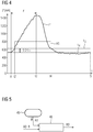
- FIG 4 shows an example of the time curve of the low-pass filtered motor current I * when door 3 is driven in opening direction O.
- no force F acts on side wall 16 of door 3, so that motor current I * corresponds to reference value I R .
- a force acts on the side wall 16 of the door 3 in the closing direction S.
- the recognition algorithm 43 sets an output signal AS active.
- the motor current I * increases until the force on the side wall 16 ceases at time t3.
- the motor current then decreases to I * and reaches the point in time t4 the limit value I G at which the output signal AS is reset again.
- the motor current I * then falls further, in order to then level itself back to the reference value I R at time t5.
- the signal AS is fed to the automatic control system 44.
- the automatic control system 44 When a release signal AS_R is present for “assisted stopping”, the automatic control system 44 generates a command ST for deleting the currently present drive order, which leads to the movement of the door 3 being stopped.
- a third analysis method that can be implemented by the analysis and evaluation unit 11 can aim at the fact that when the door 3 moves in one of the driving directions O, S and a permanent force is applied to the side surface 16 of the door 3 in this driving direction, the motor 2 is controlled in such a way that that the movement of the door 3 in the direction of travel takes place at a lower speed than during normal travel.
- This function can be referred to as “assisted drive” and enables the door 3 to move synchronously with a movement of an operator in the direction of travel.
- the analysis and evaluation unit 11 comprises according to FIG 5 a detection algorithm 45 and an associated automatic control system 46 for the "assisted driving" function.
- the detection algorithm 45 is also based on an analysis of the low-pass filtered motor current I *, in turn an evaluation of an actual value of the current I * based on the automatically learned reference value I R.
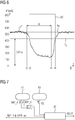
- FIG 6 shows an example of the time profile of the low-pass filtered motor current I * when door 3 in Opening direction O.
- the detection algorithm 45 sets an output signal AD active.
- the motor current I * continues to drop until the force F on the side wall 16 ceases at time t3.
- the motor current I * then rises again and, at time t4, reaches the limit value I G at which the output signal AD is reset again.
- the motor current I * then rises further in order to then level itself back to the reference value I R at time t5.
- the detection algorithm 45 can be flexibly adapted to different door systems with regard to its sensitivity.
- the signal AD of the automatic control 46 is supplied.
- a release signal AD_R for "assisted driving” is present, the automatic control system 46 generates a command RD for changing an existing driving order at normal speed to a driving order at reduced speed.
- the functions “pulse starting” and “assisted stopping” are combined with one another in the analysis and evaluation unit 11.
- the analysis and evaluation unit 11 has both the detection algorithm 41 for the “impulse start” and the detection algorithm 43 for the “assisted stopping” as well as in addition an automatic control system 47 is available for these combined functions.
- the automatic control system 47 can be activated via an extension signal "Supported stopping" IMP_R_ext in connection with the enable signal IMP_R for the "impulse start".
- the "Assisted stopping" function is a dynamic function that can be switched on and off while driving.
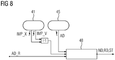
- the functions "impulse starting” and “assisted driving” are combined with one another in the analysis and evaluation unit 11.
- the analysis and evaluation unit 11 has both the recognition algorithm 41 for the "impulse starting” function and the recognition algorithm 45 for the "assisted driving” function, as well as an automatic control system 48 for these combined functions.
- the automatic control system 48 is activated via the release signal AD_R for the "assisted driving" function.
- the "Impulse start” function is first active and generates a command ND for a drive order at normal speed for door 3 in opening direction O. If the manual force in opening direction O continues continues, the "assisted driving” function becomes active and generates an output signal AD, whereupon the automatic control system 48 converts the command ND for the driving order ND at normal speed into a command RD for a driving order at reduced speed. As long as the manual force F continues in the opening direction O, the signal AD is also still active. As soon as but the manual force is not applied, the signal AD is reset. The automatic control system 48 thereupon generates a command ST for deleting the drive order, which leads to the door 3 stopping. A corresponding functionality works with a manual force F 'in the closing direction S.
- the analysis method described to determine the effect of a force in the direction of travel (i.e. a support force) or against the direction of travel (i.e. a counterforce) of a door or a door leaf by comparing the motor current (or intermediate circuit current) with a reference value that was automatically learned, for example when the door drive was started up and represents the current without the presence of a manual counterforce or support force, can be used in addition to sliding doors on all types of doors that can be moved by means of an electric drive, for example also on pivoting doors, revolving doors, folding doors and flap doors.
- the functions derived as a result of this analysis, such as "assisted driving" or "assisted braking” can also be used - possibly in a slightly adapted form - on all types of doors that can be moved by means of an electric drive.
Landscapes
- Power-Operated Mechanisms For Wings (AREA)
Claims (15)
- Procédé de commande d'un entraînement (2) électrique d'une porte (3) ou d'un vantail de porte,
dans lequel la porte (3) ou le vantail de porte peut être déplacée, dans un premier sens (S) de déplacement, d'une position ouverte à une position fermée et inversement, dans un deuxième sens (O) de déplacement, de la position fermée à la position ouverte,
dans lequel, pour le déplacement de la porte ou du vantail de porte dans au moins l'un des deux sens de déplacement, l'entraînement peut être commandé par des applications (F) de force manuelle à la porte (3) ou au vantail de porte, et dans lequel la porte (2) ou le vantail de porte a au moins une surface (16) latérale, s'étendant dans les deux sens de déplacement,
dans lequel, pour le déplacement de la porte (3) ou du vantail de porte, on commande l'entraînement (2) par des applications (F) de force manuelle, qui s'appliquent dans l'un des sens (S, O) de déplacement à la surface (16) latérale de la porte (3) ou du vantail de porte ou à une pièce (19), qui y est disposée,
caractérisé en ce que, lors d'un déplacement de la porte (3) ou du vantail de porte dans l'un des sens (S, O) de déplacement et d'une application (F) de force permanente à la surface (16) latérale de la porte (3) ou du vantail de porte dans ce sens (S, O) de déplacement, on commande l'entraînement (2) de manière à ce que le déplacement de la porte (2) ou du vantail de porte dans le sens (S, O) de déplacement ait lieu à une vitesse définie à l'avance. - Procédé suivant la revendication 1, caractérisé en ce que, pour la commande de l'entraînement (2), on détermine une durée et/ou un sens et/ou une intensité des applications (F) de force manuelle.
- Procédé suivant la revendication 2, caractérisé en ce que, lors d'un déplacement de l'entraînement (2), on détermine la durée et/ou la direction et/ou l'intensité des applications (S) de force manuelle au moyen d'un courant (I) d'alimentation ou d'un courant (I') de circuit intermédiaire d'une alimentation (5) en tension ou en courant de l'entraînement (2).
- Procédé suivant la revendication 3, caractérisé en ce que, pour la détermination de la durée et/ou la direction et/ou l'intensité des applications (F) de force manuelle, on compare une valeur en cours du courant (I) d'alimentation ou du courant de circuit intermédiaire à une valeur de référence apprise, de préférence, automatiquement.
- Procédé suivant l'une des revendications 2 à 4, caractérisé en ce que, lorsqu'il n'y a pas de déplacement de l'entraînement (2), on détermine la durée et/ou la direction et/ou l'intensité des applications de force manuelle au moyen d'un trajet incrémentiel provoqué par les applications (F) de force et/ou d'une vitesse, provoquée par les applications (F) de force, de l'entraînement (2) ou de la porte (3).
- Procédé suivant l'une des revendications précédentes, caractérisé en ce que, lorsqu'il y a une immobilité de la porte (3) et une application (F) de force manuelle sous forme d'impulsions dans l'un des sens (S, O) de déplacement, on commande l'entraînement (2) de manière à ce que la porte (3) se déplace dans ce sens (S, O) de déplacement.
- Procédé suivant l'une des revendications précédentes, caractérisé en ce que, lorsqu'il y a un déplacement de la porte dans l'un des sens (S, O) de déplacement et une application de force de type poussé à la porte, contrairement à ce sens (S, O) de déplacement, on commande l'entraînement (2) de manière à faire cesser le déplacement de la porte (3) dans le sens (S, O) de déplacement.
- Procédé suivant l'une des revendications précédentes, dans lequel les applications (F) de force dans l'un des sens (S, O) de déplacement s'appliquent à la surface (16) latérale de la porte (3).
- Dispositif (1) de commande de porte pour un entraînement (2) électrique d'une porte (3) ou d'un vantail de porte, dans lequel la porte (3) ou le vantail de porte peut être déplacé dans un premier sens (S) de déplacement, d'une position ouverte à une position fermée et inversement dans un deuxième sens (O) de déplacement de la position fermée à la position ouverte,
dans lequel la porte (3) ou le vantail de porte a au moins une surface (16) latérale s'étendant dans les deux sens (S, O) de déplacement,
dans lequel le dispositif (1) de commande de porte est constitué de manière à ce que, pour le déplacement de la porte (3) ou du vantail de porte dans au moins l'un des deux sens (S, O) de déplacement, il commande l'entraînement (2) en fonction d'applications de force manuelle, qui s'appliquent dans l'un des sens (S, O) de déplacement à la surface (16) latérale de la porte (3) ou du vantail de porte ou à une pièce (19), qui y est disposée,
caractérisé en ce que le dispositif (1) de commande de porte est constitué de manière à ce que, lors d'un déplacement de la porte (3) ou du vantail de porte dans l'un des sens (S, O) de déplacement et d'une application (F) de force permanente à la surface (16) latérale de la porte (3) ou du vantail de porte dans ce sens (S, O) de déplacement, il commande l'entraînement (2) de manière à ce que le déplacement de la porte (2) ou du vantail de porte dans le sens (S, O) de déplacement ait lieu à une vitesse définie à l'avance. - Dispositif (1) de commande de porte suivant la revendication 9, caractérisé par au moins une unité (11) d'analyse et d'exploitation pour la détermination d'une durée et/ou d'un sens et/ou d'une intensité des applications (F) de force manuelle.
- Dispositif (1) de commande de porte suivant la revendication 10, caractérisé en ce que l'unité (11) d'analyse et d'exploitation est reliée à un capteur (22) de détection d'un courant (I) d'alimentation ou d'un courant de circuit intermédiaire pour l'entraînement (2) et est constituée de manière à, lorsqu'il y a un déplacement de l'entraînement (2), il détermine la durée et/ou le sens et/ou l'intensité des applications (F) de force manuelle par une comparaison d'une valeur en cours du courant (I) d'alimentation ou du courant de circuit intermédiaire à une valeur de référence apprise, de préférence, automatiquement.
- Dispositif (1) de commande de porte suivant la revendication 10, caractérisé en ce que l'unité (11) d'analyse et d'exploitation est reliée à un indicateur (21) d'incrément pour la détection d'un trajet incrémentiel et/ou d'une vitesse de l'entraînement ou de la porte (2) et est constituée de manière à déterminer, lorsqu'il n'y a pas de déplacement de l'entraînement (2), la durée et/ou le sens et/ou l'intensité des applications de force manuelle au moyen d'un trajet incrémentiel provoqué les applications de force et/ou d'une vitesse, provoquée par les applications de force, de l'entraînement (2) ou de la porte (3).
- Dispositif (1) de commande de porte suivant l'une des revendications 9 à 12, caractérisé en ce qu'il est constitué de manière à commander, lorsqu'il y a un déplacement de la porte (3) dans l'un des sens (S, O) de déplacement et d'une application (F) de force de type poussé à la surface (16) latérale de la porte, contrairement au sens (S, O) de déplacement, l'entraînement (2) de manière à faire cesser le déplacement de la porte (3) dans le sens (S, O) de déplacement.
- Dispositif (1) de commande de porte suivant l'une des revendications 9 à 13,
dans lequel les applications (F) de force manuelle s'appliquent dans l'un des sens (S, O) de déplacement à la surface (16) latérale de la porte (3). - Dispositif (1) de commande de porte suivant l'une des revendications 9 à 14, caractérisé en ce qu'il est constitué de manière à commander, lorsqu'il n'y a pas de déplacement de la porte (3) et qu'il y a une application (F) de force manuelle sous forme d'impulsions dans l'un des sens (S, O) de déplacement, l'entraînement (2) de manière à déplacer la porte (3) dans ce sens (S, O) de déplacement.
Applications Claiming Priority (2)
| Application Number | Priority Date | Filing Date | Title |
|---|---|---|---|
| DE102013224148.8A DE102013224148A1 (de) | 2013-11-26 | 2013-11-26 | Verfahren zur Steuerung eines elektrischen Antriebs einer Tür oder eines Türflügels sowie Türsteuereinrichtung |
| PCT/EP2014/073507 WO2015078660A1 (fr) | 2013-11-26 | 2014-11-03 | Procédé de commande d'un entraînement électrique d'une porte ou d'un battant de porte et dispositif de commande de porte |
Publications (2)
| Publication Number | Publication Date |
|---|---|
| EP3044397A1 EP3044397A1 (fr) | 2016-07-20 |
| EP3044397B1 true EP3044397B1 (fr) | 2020-12-30 |
Family
ID=51894009
Family Applications (1)
| Application Number | Title | Priority Date | Filing Date |
|---|---|---|---|
| EP14796463.9A Active EP3044397B1 (fr) | 2013-11-26 | 2014-11-03 | Procédé pour commander un actionneur électrique d'une porte ou vantail de porte et dispositif de commande de porte |
Country Status (3)
| Country | Link |
|---|---|
| EP (1) | EP3044397B1 (fr) |
| DE (1) | DE102013224148A1 (fr) |
| WO (1) | WO2015078660A1 (fr) |
Families Citing this family (6)
| Publication number | Priority date | Publication date | Assignee | Title |
|---|---|---|---|---|
| DE102016205367A1 (de) | 2016-03-31 | 2017-10-05 | Meiko Maschinenbau Gmbh & Co. Kg | Reinigungsvorrichtung und Verfahren zum Reinigen von Reinigungsgut |
| DE102019107187A1 (de) * | 2019-03-20 | 2020-09-24 | Brose Fahrzeugteile Se & Co. Kommanditgesellschaft, Bamberg | Steuersystem zur Ansteuerung einer Antriebsanordnung |
| DE102020125098A1 (de) * | 2020-09-25 | 2022-03-31 | Dormakaba Deutschland Gmbh | Verfahren zum Verschwenken eines Flügels mit einer Antriebseinrichtung und Antriebseinrichtung zum Verschwenken eines Flügels |
| DE102021204691A1 (de) * | 2021-05-10 | 2022-11-10 | Geze Gmbh | Antrieb für eine Tür |
| CN114622500B (zh) * | 2022-01-27 | 2024-01-16 | 浙江大华技术股份有限公司 | 闸翼转向学习方法、系统、闸机、计算机设备和存储介质 |
| DE102023210163A1 (de) * | 2023-10-17 | 2025-04-17 | Geze Gmbh | Türsystem |
Family Cites Families (6)
| Publication number | Priority date | Publication date | Assignee | Title |
|---|---|---|---|---|
| JPH10252349A (ja) * | 1997-03-11 | 1998-09-22 | Asmo Co Ltd | 車両ドア開閉装置 |
| DE19956076A1 (de) | 1999-11-22 | 2001-05-31 | Siemens Ag | Antriebseinrichtung für Aufzugtüren |
| DE202004017100U1 (de) * | 2004-10-29 | 2005-03-03 | Gretsch-Unitas GmbH Baubeschläge | Beschlag für eine Hebe-Schiebe-Tür |
| DE102006040232A1 (de) | 2006-08-28 | 2008-03-13 | Siemens Ag | Türantrieb für eine automatische Tür |
| DE502007002673D1 (de) * | 2007-03-12 | 2010-03-11 | Delphi Tech Inc | Türbetätigungsverfahren |
| DE102011004019B4 (de) | 2011-02-14 | 2015-02-12 | Siemens Aktiengesellschaft | Elektrisch angetriebene Tür |
-
2013
- 2013-11-26 DE DE102013224148.8A patent/DE102013224148A1/de not_active Ceased
-
2014
- 2014-11-03 WO PCT/EP2014/073507 patent/WO2015078660A1/fr not_active Ceased
- 2014-11-03 EP EP14796463.9A patent/EP3044397B1/fr active Active
Non-Patent Citations (1)
| Title |
|---|
| None * |
Also Published As
| Publication number | Publication date |
|---|---|
| EP3044397A1 (fr) | 2016-07-20 |
| WO2015078660A1 (fr) | 2015-06-04 |
| DE102013224148A1 (de) | 2015-05-28 |
Similar Documents
| Publication | Publication Date | Title |
|---|---|---|
| EP3044397B1 (fr) | Procédé pour commander un actionneur électrique d'une porte ou vantail de porte et dispositif de commande de porte | |
| EP2653642B1 (fr) | Procédé de fonctionnement d'un système de pliage et système de pliage | |
| EP2704925B1 (fr) | Procédé d'actionnement d'un ensemble élément de fermeture d'un véhicule automobile | |
| EP3361028B1 (fr) | Unité d'entraînement | |
| EP0910883B1 (fr) | Procede de commande de la fermeture de dispositifs de fermeture pourvus d'au moins une partie deplacee par moteur electrique | |
| EP0751274A1 (fr) | Dispositif d'actionnement | |
| DE3933266A1 (de) | Verfahren zur steuerung eines elektromotors fuer einen rolladen, insbesondere faltrolladen und steuereinheit hierfuer | |
| EP2558669B1 (fr) | Procédé permettant de faire fonctionner un dispositif de fermeture et dispositif de fermeture | |
| DE102010014806B4 (de) | Torantriebsvorrichtung, damit versehener Gebäudeabschluss, Torsystem und Herstell- und Antriebsverfahren | |
| EP2369124B1 (fr) | Commande de moteur tubulaire pour un dispositif d'occultation | |
| EP3240936B1 (fr) | Procédé permettant de faire fonctionner un entraînement de porte, commande d'entraînement de porte, entraînement de porte et porte battante | |
| DE102009035449B3 (de) | Verfahren und Vorrichtung zur zeitgesteuerten Einklemmerkennung | |
| WO2018019601A1 (fr) | Procédé et dispositif de détection d'un coincement et/ou d'une limite de force de fermeture d'une partie déplaçable au moyen d'un moteur électrique | |
| WO2022167043A1 (fr) | Procédé d'assistance motorisée du mouvement d'une porte de véhicule | |
| EP2388424B1 (fr) | Dispositif d'entraînement de porte et installation de porte en étant équipée | |
| DE102007004445B4 (de) | Antriebsvorrichtung | |
| EP1251226A2 (fr) | Système de lève-vitre et méthode pour contrôler une pluralité de lève-vitres | |
| DE19700828B4 (de) | Verfahren zum Betrieb einer automatischen Türanlage | |
| DE102011078832B4 (de) | Gebäudetür | |
| EP2444585A2 (fr) | Procédé de surveillance de mouvements sur un portail roulant et dispositif d'exécution du procédé | |
| EP3963164A1 (fr) | Unité de commande conçue pour un entraînement de porte ou de fenêtre | |
| DE4337015B4 (de) | Verfahren zur Steuerung eines motorischen Antriebs einer Tür- oder Fensteranlage | |
| DE10253643A1 (de) | Fensterhebersteuerung und Verfahren zur Steuerung von Fensterhebern | |
| EP3245372B1 (fr) | Procédé pour faire fonctionner un dispositif d'entraînement de porte, commande d'entraînement de porte et porte battante | |
| EP2634358A1 (fr) | Détection d'obstacles intelligente |
Legal Events
| Date | Code | Title | Description |
|---|---|---|---|
| PUAI | Public reference made under article 153(3) epc to a published international application that has entered the european phase |
Free format text: ORIGINAL CODE: 0009012 |
|
| 17P | Request for examination filed |
Effective date: 20160415 |
|
| AK | Designated contracting states |
Kind code of ref document: A1 Designated state(s): AL AT BE BG CH CY CZ DE DK EE ES FI FR GB GR HR HU IE IS IT LI LT LU LV MC MK MT NL NO PL PT RO RS SE SI SK SM TR |
|
| AX | Request for extension of the european patent |
Extension state: BA ME |
|
| DAX | Request for extension of the european patent (deleted) | ||
| RAP1 | Party data changed (applicant data changed or rights of an application transferred) |
Owner name: SIEMENS AKTIENGESELLSCHAFT |
|
| STAA | Information on the status of an ep patent application or granted ep patent |
Free format text: STATUS: EXAMINATION IS IN PROGRESS |
|
| 17Q | First examination report despatched |
Effective date: 20180301 |
|
| GRAP | Despatch of communication of intention to grant a patent |
Free format text: ORIGINAL CODE: EPIDOSNIGR1 |
|
| STAA | Information on the status of an ep patent application or granted ep patent |
Free format text: STATUS: GRANT OF PATENT IS INTENDED |
|
| INTG | Intention to grant announced |
Effective date: 20200703 |
|
| GRAS | Grant fee paid |
Free format text: ORIGINAL CODE: EPIDOSNIGR3 |
|
| GRAA | (expected) grant |
Free format text: ORIGINAL CODE: 0009210 |
|
| STAA | Information on the status of an ep patent application or granted ep patent |
Free format text: STATUS: THE PATENT HAS BEEN GRANTED |
|
| AK | Designated contracting states |
Kind code of ref document: B1 Designated state(s): AL AT BE BG CH CY CZ DE DK EE ES FI FR GB GR HR HU IE IS IT LI LT LU LV MC MK MT NL NO PL PT RO RS SE SI SK SM TR |
|
| REG | Reference to a national code |
Ref country code: GB Ref legal event code: FG4D Free format text: NOT ENGLISH |
|
| REG | Reference to a national code |
Ref country code: AT Ref legal event code: REF Ref document number: 1350082 Country of ref document: AT Kind code of ref document: T Effective date: 20210115 |
|
| REG | Reference to a national code |
Ref country code: DE Ref legal event code: R096 Ref document number: 502014015158 Country of ref document: DE |
|
| REG | Reference to a national code |
Ref country code: IE Ref legal event code: FG4D Free format text: LANGUAGE OF EP DOCUMENT: GERMAN |
|
| PG25 | Lapsed in a contracting state [announced via postgrant information from national office to epo] |
Ref country code: GR Free format text: LAPSE BECAUSE OF FAILURE TO SUBMIT A TRANSLATION OF THE DESCRIPTION OR TO PAY THE FEE WITHIN THE PRESCRIBED TIME-LIMIT Effective date: 20210331 Ref country code: NO Free format text: LAPSE BECAUSE OF FAILURE TO SUBMIT A TRANSLATION OF THE DESCRIPTION OR TO PAY THE FEE WITHIN THE PRESCRIBED TIME-LIMIT Effective date: 20210330 Ref country code: RS Free format text: LAPSE BECAUSE OF FAILURE TO SUBMIT A TRANSLATION OF THE DESCRIPTION OR TO PAY THE FEE WITHIN THE PRESCRIBED TIME-LIMIT Effective date: 20201230 Ref country code: FI Free format text: LAPSE BECAUSE OF FAILURE TO SUBMIT A TRANSLATION OF THE DESCRIPTION OR TO PAY THE FEE WITHIN THE PRESCRIBED TIME-LIMIT Effective date: 20201230 |
|
| PG25 | Lapsed in a contracting state [announced via postgrant information from national office to epo] |
Ref country code: LV Free format text: LAPSE BECAUSE OF FAILURE TO SUBMIT A TRANSLATION OF THE DESCRIPTION OR TO PAY THE FEE WITHIN THE PRESCRIBED TIME-LIMIT Effective date: 20201230 Ref country code: SE Free format text: LAPSE BECAUSE OF FAILURE TO SUBMIT A TRANSLATION OF THE DESCRIPTION OR TO PAY THE FEE WITHIN THE PRESCRIBED TIME-LIMIT Effective date: 20201230 Ref country code: BG Free format text: LAPSE BECAUSE OF FAILURE TO SUBMIT A TRANSLATION OF THE DESCRIPTION OR TO PAY THE FEE WITHIN THE PRESCRIBED TIME-LIMIT Effective date: 20210330 |
|
| REG | Reference to a national code |
Ref country code: NL Ref legal event code: MP Effective date: 20201230 |
|
| PG25 | Lapsed in a contracting state [announced via postgrant information from national office to epo] |
Ref country code: HR Free format text: LAPSE BECAUSE OF FAILURE TO SUBMIT A TRANSLATION OF THE DESCRIPTION OR TO PAY THE FEE WITHIN THE PRESCRIBED TIME-LIMIT Effective date: 20201230 |
|
| REG | Reference to a national code |
Ref country code: LT Ref legal event code: MG9D |
|
| PG25 | Lapsed in a contracting state [announced via postgrant information from national office to epo] |
Ref country code: LT Free format text: LAPSE BECAUSE OF FAILURE TO SUBMIT A TRANSLATION OF THE DESCRIPTION OR TO PAY THE FEE WITHIN THE PRESCRIBED TIME-LIMIT Effective date: 20201230 Ref country code: PT Free format text: LAPSE BECAUSE OF FAILURE TO SUBMIT A TRANSLATION OF THE DESCRIPTION OR TO PAY THE FEE WITHIN THE PRESCRIBED TIME-LIMIT Effective date: 20210430 Ref country code: SK Free format text: LAPSE BECAUSE OF FAILURE TO SUBMIT A TRANSLATION OF THE DESCRIPTION OR TO PAY THE FEE WITHIN THE PRESCRIBED TIME-LIMIT Effective date: 20201230 Ref country code: RO Free format text: LAPSE BECAUSE OF FAILURE TO SUBMIT A TRANSLATION OF THE DESCRIPTION OR TO PAY THE FEE WITHIN THE PRESCRIBED TIME-LIMIT Effective date: 20201230 Ref country code: NL Free format text: LAPSE BECAUSE OF FAILURE TO SUBMIT A TRANSLATION OF THE DESCRIPTION OR TO PAY THE FEE WITHIN THE PRESCRIBED TIME-LIMIT Effective date: 20201230 Ref country code: EE Free format text: LAPSE BECAUSE OF FAILURE TO SUBMIT A TRANSLATION OF THE DESCRIPTION OR TO PAY THE FEE WITHIN THE PRESCRIBED TIME-LIMIT Effective date: 20201230 Ref country code: CZ Free format text: LAPSE BECAUSE OF FAILURE TO SUBMIT A TRANSLATION OF THE DESCRIPTION OR TO PAY THE FEE WITHIN THE PRESCRIBED TIME-LIMIT Effective date: 20201230 |
|
| PG25 | Lapsed in a contracting state [announced via postgrant information from national office to epo] |
Ref country code: PL Free format text: LAPSE BECAUSE OF FAILURE TO SUBMIT A TRANSLATION OF THE DESCRIPTION OR TO PAY THE FEE WITHIN THE PRESCRIBED TIME-LIMIT Effective date: 20201230 |
|
| PG25 | Lapsed in a contracting state [announced via postgrant information from national office to epo] |
Ref country code: IS Free format text: LAPSE BECAUSE OF FAILURE TO SUBMIT A TRANSLATION OF THE DESCRIPTION OR TO PAY THE FEE WITHIN THE PRESCRIBED TIME-LIMIT Effective date: 20210430 |
|
| REG | Reference to a national code |
Ref country code: DE Ref legal event code: R097 Ref document number: 502014015158 Country of ref document: DE |
|
| PG25 | Lapsed in a contracting state [announced via postgrant information from national office to epo] |
Ref country code: AL Free format text: LAPSE BECAUSE OF FAILURE TO SUBMIT A TRANSLATION OF THE DESCRIPTION OR TO PAY THE FEE WITHIN THE PRESCRIBED TIME-LIMIT Effective date: 20201230 |
|
| PLBE | No opposition filed within time limit |
Free format text: ORIGINAL CODE: 0009261 |
|
| STAA | Information on the status of an ep patent application or granted ep patent |
Free format text: STATUS: NO OPPOSITION FILED WITHIN TIME LIMIT |
|
| PG25 | Lapsed in a contracting state [announced via postgrant information from national office to epo] |
Ref country code: ES Free format text: LAPSE BECAUSE OF FAILURE TO SUBMIT A TRANSLATION OF THE DESCRIPTION OR TO PAY THE FEE WITHIN THE PRESCRIBED TIME-LIMIT Effective date: 20201230 Ref country code: DK Free format text: LAPSE BECAUSE OF FAILURE TO SUBMIT A TRANSLATION OF THE DESCRIPTION OR TO PAY THE FEE WITHIN THE PRESCRIBED TIME-LIMIT Effective date: 20201230 |
|
| 26N | No opposition filed |
Effective date: 20211001 |
|
| PG25 | Lapsed in a contracting state [announced via postgrant information from national office to epo] |
Ref country code: SI Free format text: LAPSE BECAUSE OF FAILURE TO SUBMIT A TRANSLATION OF THE DESCRIPTION OR TO PAY THE FEE WITHIN THE PRESCRIBED TIME-LIMIT Effective date: 20201230 |
|
| PG25 | Lapsed in a contracting state [announced via postgrant information from national office to epo] |
Ref country code: IS Free format text: LAPSE BECAUSE OF FAILURE TO SUBMIT A TRANSLATION OF THE DESCRIPTION OR TO PAY THE FEE WITHIN THE PRESCRIBED TIME-LIMIT Effective date: 20210430 |
|
| PG25 | Lapsed in a contracting state [announced via postgrant information from national office to epo] |
Ref country code: MC Free format text: LAPSE BECAUSE OF FAILURE TO SUBMIT A TRANSLATION OF THE DESCRIPTION OR TO PAY THE FEE WITHIN THE PRESCRIBED TIME-LIMIT Effective date: 20201230 |
|
| REG | Reference to a national code |
Ref country code: CH Ref legal event code: PL |
|
| GBPC | Gb: european patent ceased through non-payment of renewal fee |
Effective date: 20211103 |
|
| PG25 | Lapsed in a contracting state [announced via postgrant information from national office to epo] |
Ref country code: LU Free format text: LAPSE BECAUSE OF NON-PAYMENT OF DUE FEES Effective date: 20211103 Ref country code: BE Free format text: LAPSE BECAUSE OF NON-PAYMENT OF DUE FEES Effective date: 20211130 |
|
| REG | Reference to a national code |
Ref country code: BE Ref legal event code: MM Effective date: 20211130 |
|
| PG25 | Lapsed in a contracting state [announced via postgrant information from national office to epo] |
Ref country code: LI Free format text: LAPSE BECAUSE OF NON-PAYMENT OF DUE FEES Effective date: 20211130 Ref country code: CH Free format text: LAPSE BECAUSE OF NON-PAYMENT OF DUE FEES Effective date: 20211130 |
|
| PG25 | Lapsed in a contracting state [announced via postgrant information from national office to epo] |
Ref country code: IE Free format text: LAPSE BECAUSE OF NON-PAYMENT OF DUE FEES Effective date: 20211103 Ref country code: GB Free format text: LAPSE BECAUSE OF NON-PAYMENT OF DUE FEES Effective date: 20211103 |
|
| REG | Reference to a national code |
Ref country code: AT Ref legal event code: MM01 Ref document number: 1350082 Country of ref document: AT Kind code of ref document: T Effective date: 20211103 |
|
| PG25 | Lapsed in a contracting state [announced via postgrant information from national office to epo] |
Ref country code: AT Free format text: LAPSE BECAUSE OF NON-PAYMENT OF DUE FEES Effective date: 20211103 |
|
| PG25 | Lapsed in a contracting state [announced via postgrant information from national office to epo] |
Ref country code: HU Free format text: LAPSE BECAUSE OF FAILURE TO SUBMIT A TRANSLATION OF THE DESCRIPTION OR TO PAY THE FEE WITHIN THE PRESCRIBED TIME-LIMIT; INVALID AB INITIO Effective date: 20141103 |
|
| PG25 | Lapsed in a contracting state [announced via postgrant information from national office to epo] |
Ref country code: CY Free format text: LAPSE BECAUSE OF FAILURE TO SUBMIT A TRANSLATION OF THE DESCRIPTION OR TO PAY THE FEE WITHIN THE PRESCRIBED TIME-LIMIT Effective date: 20201230 |
|
| PG25 | Lapsed in a contracting state [announced via postgrant information from national office to epo] |
Ref country code: SM Free format text: LAPSE BECAUSE OF FAILURE TO SUBMIT A TRANSLATION OF THE DESCRIPTION OR TO PAY THE FEE WITHIN THE PRESCRIBED TIME-LIMIT Effective date: 20201230 |
|
| PG25 | Lapsed in a contracting state [announced via postgrant information from national office to epo] |
Ref country code: MK Free format text: LAPSE BECAUSE OF FAILURE TO SUBMIT A TRANSLATION OF THE DESCRIPTION OR TO PAY THE FEE WITHIN THE PRESCRIBED TIME-LIMIT Effective date: 20201230 |
|
| PG25 | Lapsed in a contracting state [announced via postgrant information from national office to epo] |
Ref country code: MT Free format text: LAPSE BECAUSE OF FAILURE TO SUBMIT A TRANSLATION OF THE DESCRIPTION OR TO PAY THE FEE WITHIN THE PRESCRIBED TIME-LIMIT Effective date: 20201230 |
|
| PGFP | Annual fee paid to national office [announced via postgrant information from national office to epo] |
Ref country code: DE Payment date: 20250120 Year of fee payment: 11 |
|
| PG25 | Lapsed in a contracting state [announced via postgrant information from national office to epo] |
Ref country code: TR Free format text: LAPSE BECAUSE OF FAILURE TO SUBMIT A TRANSLATION OF THE DESCRIPTION OR TO PAY THE FEE WITHIN THE PRESCRIBED TIME-LIMIT Effective date: 20201230 |
|
| PGFP | Annual fee paid to national office [announced via postgrant information from national office to epo] |
Ref country code: IT Payment date: 20251125 Year of fee payment: 12 |
|
| PGFP | Annual fee paid to national office [announced via postgrant information from national office to epo] |
Ref country code: FR Payment date: 20251114 Year of fee payment: 12 |