EP3044397B1 - Method for controlling a electrical drive of a door or door wing and door control device - Google Patents
Method for controlling a electrical drive of a door or door wing and door control device Download PDFInfo
- Publication number
- EP3044397B1 EP3044397B1 EP14796463.9A EP14796463A EP3044397B1 EP 3044397 B1 EP3044397 B1 EP 3044397B1 EP 14796463 A EP14796463 A EP 14796463A EP 3044397 B1 EP3044397 B1 EP 3044397B1
- Authority
- EP
- European Patent Office
- Prior art keywords
- door
- travel
- drive
- directions
- wing
- Prior art date
- Legal status (The legal status is an assumption and is not a legal conclusion. Google has not performed a legal analysis and makes no representation as to the accuracy of the status listed.)
- Active
Links
Images

Classifications
-
- E—FIXED CONSTRUCTIONS
- E05—LOCKS; KEYS; WINDOW OR DOOR FITTINGS; SAFES
- E05F—DEVICES FOR MOVING WINGS INTO OPEN OR CLOSED POSITION; CHECKS FOR WINGS; WING FITTINGS NOT OTHERWISE PROVIDED FOR, CONCERNED WITH THE FUNCTIONING OF THE WING
- E05F15/00—Power-operated mechanisms for wings
- E05F15/70—Power-operated mechanisms for wings with automatic actuation
-
- E—FIXED CONSTRUCTIONS
- E05—LOCKS; KEYS; WINDOW OR DOOR FITTINGS; SAFES
- E05F—DEVICES FOR MOVING WINGS INTO OPEN OR CLOSED POSITION; CHECKS FOR WINGS; WING FITTINGS NOT OTHERWISE PROVIDED FOR, CONCERNED WITH THE FUNCTIONING OF THE WING
- E05F15/00—Power-operated mechanisms for wings
- E05F15/60—Power-operated mechanisms for wings using electrical actuators
- E05F15/603—Power-operated mechanisms for wings using electrical actuators using rotary electromotors
- E05F15/632—Power-operated mechanisms for wings using electrical actuators using rotary electromotors for horizontally-sliding wings
-
- E—FIXED CONSTRUCTIONS
- E05—LOCKS; KEYS; WINDOW OR DOOR FITTINGS; SAFES
- E05Y—INDEXING SCHEME ASSOCIATED WITH SUBCLASSES E05D AND E05F, RELATING TO CONSTRUCTION ELEMENTS, ELECTRIC CONTROL, POWER SUPPLY, POWER SIGNAL OR TRANSMISSION, USER INTERFACES, MOUNTING OR COUPLING, DETAILS, ACCESSORIES, AUXILIARY OPERATIONS NOT OTHERWISE PROVIDED FOR, APPLICATION THEREOF
- E05Y2400/00—Electronic control; Electrical power; Power supply; Power or signal transmission; User interfaces
- E05Y2400/10—Electronic control
- E05Y2400/30—Electronic control of motors
- E05Y2400/3013—Electronic control of motors during manual wing operation
- E05Y2400/3015—Power assistance
-
- E—FIXED CONSTRUCTIONS
- E05—LOCKS; KEYS; WINDOW OR DOOR FITTINGS; SAFES
- E05Y—INDEXING SCHEME ASSOCIATED WITH SUBCLASSES E05D AND E05F, RELATING TO CONSTRUCTION ELEMENTS, ELECTRIC CONTROL, POWER SUPPLY, POWER SIGNAL OR TRANSMISSION, USER INTERFACES, MOUNTING OR COUPLING, DETAILS, ACCESSORIES, AUXILIARY OPERATIONS NOT OTHERWISE PROVIDED FOR, APPLICATION THEREOF
- E05Y2400/00—Electronic control; Electrical power; Power supply; Power or signal transmission; User interfaces
- E05Y2400/10—Electronic control
- E05Y2400/30—Electronic control of motors
- E05Y2400/3013—Electronic control of motors during manual wing operation
- E05Y2400/3016—Overriding existing wing movement
-
- E—FIXED CONSTRUCTIONS
- E05—LOCKS; KEYS; WINDOW OR DOOR FITTINGS; SAFES
- E05Y—INDEXING SCHEME ASSOCIATED WITH SUBCLASSES E05D AND E05F, RELATING TO CONSTRUCTION ELEMENTS, ELECTRIC CONTROL, POWER SUPPLY, POWER SIGNAL OR TRANSMISSION, USER INTERFACES, MOUNTING OR COUPLING, DETAILS, ACCESSORIES, AUXILIARY OPERATIONS NOT OTHERWISE PROVIDED FOR, APPLICATION THEREOF
- E05Y2400/00—Electronic control; Electrical power; Power supply; Power or signal transmission; User interfaces
- E05Y2400/10—Electronic control
- E05Y2400/30—Electronic control of motors
- E05Y2400/304—Voltage control
-
- E—FIXED CONSTRUCTIONS
- E05—LOCKS; KEYS; WINDOW OR DOOR FITTINGS; SAFES
- E05Y—INDEXING SCHEME ASSOCIATED WITH SUBCLASSES E05D AND E05F, RELATING TO CONSTRUCTION ELEMENTS, ELECTRIC CONTROL, POWER SUPPLY, POWER SIGNAL OR TRANSMISSION, USER INTERFACES, MOUNTING OR COUPLING, DETAILS, ACCESSORIES, AUXILIARY OPERATIONS NOT OTHERWISE PROVIDED FOR, APPLICATION THEREOF
- E05Y2400/00—Electronic control; Electrical power; Power supply; Power or signal transmission; User interfaces
- E05Y2400/10—Electronic control
- E05Y2400/36—Speed control, detection or monitoring
-
- E—FIXED CONSTRUCTIONS
- E05—LOCKS; KEYS; WINDOW OR DOOR FITTINGS; SAFES
- E05Y—INDEXING SCHEME ASSOCIATED WITH SUBCLASSES E05D AND E05F, RELATING TO CONSTRUCTION ELEMENTS, ELECTRIC CONTROL, POWER SUPPLY, POWER SIGNAL OR TRANSMISSION, USER INTERFACES, MOUNTING OR COUPLING, DETAILS, ACCESSORIES, AUXILIARY OPERATIONS NOT OTHERWISE PROVIDED FOR, APPLICATION THEREOF
- E05Y2400/00—Electronic control; Electrical power; Power supply; Power or signal transmission; User interfaces
- E05Y2400/10—Electronic control
- E05Y2400/44—Sensors not directly associated with the wing movement
-
- E—FIXED CONSTRUCTIONS
- E05—LOCKS; KEYS; WINDOW OR DOOR FITTINGS; SAFES
- E05Y—INDEXING SCHEME ASSOCIATED WITH SUBCLASSES E05D AND E05F, RELATING TO CONSTRUCTION ELEMENTS, ELECTRIC CONTROL, POWER SUPPLY, POWER SIGNAL OR TRANSMISSION, USER INTERFACES, MOUNTING OR COUPLING, DETAILS, ACCESSORIES, AUXILIARY OPERATIONS NOT OTHERWISE PROVIDED FOR, APPLICATION THEREOF
- E05Y2900/00—Application of doors, windows, wings or fittings thereof
- E05Y2900/10—Application of doors, windows, wings or fittings thereof for buildings or parts thereof
- E05Y2900/11—Application of doors, windows, wings or fittings thereof for buildings or parts thereof for industrial buildings
-
- E—FIXED CONSTRUCTIONS
- E05—LOCKS; KEYS; WINDOW OR DOOR FITTINGS; SAFES
- E05Y—INDEXING SCHEME ASSOCIATED WITH SUBCLASSES E05D AND E05F, RELATING TO CONSTRUCTION ELEMENTS, ELECTRIC CONTROL, POWER SUPPLY, POWER SIGNAL OR TRANSMISSION, USER INTERFACES, MOUNTING OR COUPLING, DETAILS, ACCESSORIES, AUXILIARY OPERATIONS NOT OTHERWISE PROVIDED FOR, APPLICATION THEREOF
- E05Y2900/00—Application of doors, windows, wings or fittings thereof
- E05Y2900/10—Application of doors, windows, wings or fittings thereof for buildings or parts thereof
- E05Y2900/13—Type of wing
- E05Y2900/132—Doors
Definitions
- the invention relates to a method for controlling an electric drive of a door or a door leaf according to claim 1 and a door control device according to claim 9.
- Door control devices serve to control and / or regulate at least one electric drive motor for opening or closing at least one door or one door leaf, in particular at least one sliding door or one leaf of a sliding door.
- Sliding doors are mainly found in elevators, on platforms for access control to trains, at the entrance of buildings or for personal protection in an industrial environment, e.g. on machine tools.
- direct current motors or, more recently, electronically commutated, brushless, permanently excited synchronous motors with or without a downstream gear are used as electric drive motors.
- Examples of door drives with such a door control device are in EP 1 894 877 A2 , the DE 10 2011 004 019 A1 and the EP 1 102 390 A2 disclosed.
- Door control devices of this type are increasingly being integrated into an automation system and connected to a central, higher-level controller via an industrial communication link (e.g. PROFIBUS, PROFINET).
- industrial communication link e.g. PROFIBUS, PROFINET
- a door or a door leaf is in a first direction of travel (closing direction) from an open position to a closed position and conversely movable in a second direction of travel (opening direction) from the closed position to the open position.
- first direction of travel closing direction
- second direction of travel open direction
- a so-called "Push & Go" function is already known for revolving doors.
- a short manual pushing of the door in the opening direction i.e. a force acting vertically on a side surface of the door in the direction of rotation of the door
- the revolving doors in and of themselves have little weight and could also be easily opened manually.
- the function is just a convenience function that makes it possible, for example, to open the door when there is little hand freedom.
- a fitting for a sliding door with a stationary fitting part and a fitting part attached to the movable wing of the door and a drive device for the movable fitting part is known, the wing being liftable via the fitting and that the drive device is provided with a programmable control.
- the control can be activated, among other things, by manually pushing the sash, in particular using the handle of the door, or manually pushing the sash in the opening or closing direction.
- a method for controlling a door in particular a motor vehicle door, is known, an electric motor being in operative connection with the door, the electric motor being controlled by a controller when the door is manually operated in such a way that the motor exerts a first force on the door , wherein a system-inherent second force counteracts the manual actuation of the door, wherein the first force counteracts the system-inherent second force and wherein the first force at least partially compensates for the system-inherent second force.
- An "obstacle detection” is also known from sliding doors.
- a permanent manual force on a front face of the door in the closing direction leads to a stop of the drive or a reversal of the direction of movement (reversing).
- monitoring is carried out, for example, for falling below a specified target closing speed and / or exceeding a maximum torque. Pulse monitoring of the incremental encoder is also possible.
- a permanent manual force on a front face of the door in the opening direction stops the drive.
- the electric drive of the door or the door leaf is controlled by manual forces acting in one of the directions of travel on the side surface of the door or the door leaf or a component arranged thereon (e.g. a door handle).
- a component arranged thereon e.g. a door handle.
- This is based on the idea of using the already existing side surface of the door itself as a type of "input system" for controlling the drive and thus the movement of the door, so that no additional input system is necessary. Due to the usually large area of the side surface, the operator can easily reach it by hand, especially when the operator moves with the opening or closing door. Since the side face - in contrast to an end face of the door - does not pose a risk of crushing for an operator, a risk to persons can also be avoided.
- a particularly intuitive and thus simple control of the drive and thus of the movement of a heavy door can also take place through direct manual force action in the direction or directions of travel.
- the manual force effects can either only control part of the door's movements (e.g. only starting or stopping the door) or preferably all movement sequences (e.g. also speed changes, reversing functions).
- a duration and / or direction and / or strength of the manual force effects are used to control the drive determined.
- This information can be flexibly linked with one another either in a door control itself or in one of these higher-level controls and, depending on the application, a wide variety of target specifications for the drive can be derived, for example, travel orders can be issued, deleted, interrupted or changed.
- target specifications for the drive can be derived, for example, travel orders can be issued, deleted, interrupted or changed.
- the duration and / or direction and / or strength of the manual force effects can be determined particularly easily and without additional complex sensor systems by means of a feed current of the drive or an intermediate circuit current of a current or voltage supply of the drive when the drive is moving.
- a door control device itself can derive a status of the drive from the determined values of the duration and / or direction and / or strength of the manual force action and derive responses as a function thereof.
- the status of the drive can also be reported to a higher-level control device, which then triggers a reaction by corresponding specifications to a door control device.
- the determination of the duration and / or direction and / or strength of the force action can take place particularly simply by comparing an actual value of the feed current or intermediate circuit current with a reference value that is preferably automatically learned.
- the reference value can, for example, be determined during commissioning by a learning run for the entire travel distance and represent the actual value of the feed current or intermediate circuit current without external forces acting on the door.
- the duration and / or direction and / or strength of the manual force can be determined particularly easily by means of an incremental path caused by the force and / or a speed of the drive or the door or door leaf caused by the force.
- a drive order to open or close the door or the door leaf can be generated in a simple and user-friendly manner in that, when the door or the door leaf is motionless and a pulsed manual force is exerted in one of the directions of travel, the drive is controlled in such a way that the door moves or the door leaf moves in this direction of travel.
- the drive can then, for example, be controlled in such a way that the movement of the door or the door leaf in the direction of travel is stopped. This can then also cause a travel order to be deleted.
- the drive is controlled according to the invention in such a way that the movement of the door or the door leaf in the direction of travel takes place at a predefined, in particular reduced, speed. This does not involve maintaining or changing a previous travel order. If this permanent force does not apply to an existing transport order, this can in turn cause a deletion or interruption of a transport order.
- a door control device for an electric drive of a door or a door leaf, the door or the door leaf by means of the drive in a first direction of travel (closing direction) from an open position to a closed position and vice versa in a second direction of travel (opening direction) from the closed position is movable into the open position, and wherein the door or the door leaf has at least one side surface running in the two directions of travel, is designed such that it uses the drive to move the door or the door leaf in at least one of the two directions of travel as a function of manual forces , which act in one of the directions of travel on the side surface of the door or the door leaf or a component arranged on it (e.g. door handle) controls.
- the door control device is designed such that when the door is moved in this direction of travel and there is a permanent manual force on the door in this direction, the drive is controlled in such a way that the door moves in this direction at a predefined speed.
- Door control device 1 shown in a simplified schematic diagram is used to control and / or regulate an electric drive motor 2 for opening or closing a sliding door 3.
- the door 3 is, for example, a sliding door with a high weight of preferably more than 300 kg.
- Such sliding doors are used, for example, in commercial and industrial companies.
- the electric drive motor 2 is preferably an electronically commutated, brushless, permanent magnet synchronous motor.
- the door control device 1 comprises a power section 5 for voltage / current supply of the motor 2 and a control section 10 for controlling and / or regulating the power section 5 and thus the motor 2.
- the power section 5 comprises a rectifier 6 and a commutation circuit 7 for the motor 2.
- the rectifier 6 and the commutation circuit 7 are connected to one another via an intermediate circuit 8.
- the rectifier 6 can be connected to a voltage supply network (not shown) - possibly via a network transformer.
- the control part 10 comprises a microcontroller system with a microcontroller (not shown in detail) and a data memory.
- the door control device 1 is accommodated in a housing 20 and thus forms a compact device.
- the housing 20 has a communication interface 23 for communication with an industrial communication system 30 external to the device (e.g. a data bus or network such as PROFIBUS or PROFINET).
- an industrial communication system 30 external to the device (e.g. a data bus or network such as PROFIBUS or PROFINET).
- Further door drives 9 and a higher-level controller 31 for the door drives 9 can also be coupled to the communication system 30.
- the higher-level controller 31, the communication system 30 and the door drives 9 form an automation system 35.
- the higher-level controller 31 is connected to the door control devices via the communication system 30 1 connected via their respective interface 23 to their control.
- the motor 2 drives a deflection roller 12 via its output shaft 4, which positively drives a toothed belt 13 to which the door 3 is attached via a bracket 14.
- the toothed belt 13 is guided over a second deflection roller 15 which is either not driven or - for example in the case of particularly heavy doors - is also driven by a motor that is synchronized with the motor 2.
- a toothed rack can also be provided instead of the toothed belt 13, a toothed rack can also be provided.
- the door 3 is in a first direction of travel (closing direction) by means of the motor 2, which is shown in FIG FIG 1 with "S” is designated, from an open position to a closed position and vice versa in a second direction of travel (opening direction), which in the FIG 1 with "O” is movable from the closed position to the open position.
- the door 3 has two side surfaces running in the two directions of travel S, O, of which in FIG FIG 1 only the front side surfaces 16 is visible. Furthermore, the door 3 has a front face 17 in the closing direction S and a front face 18 in the opening direction O.
- the motor 2 is in at least one of the two directions of travel S or O by manual forces acting in one of the directions S, O on the side surface 16 of the door 3 or a component arranged on it (e.g. a door handle 19), controllable.
- an analysis and evaluation unit 11 determines the duration, direction and strength of the manual force effects on the side surface 16.
- the door is not moving, this can be done by determining an incremental path X (for light doors) or a speed V (for heavy doors) of the output shaft 4 caused by a manual force, with the aid of an incremental encoder 21 coupled to it.
- the incremental encoder 21 can for this purpose also be coupled to a rotor of the motor 2, the toothed belt 13 or one of the deflection rollers 12, 15.
- predefined movement states of the door or operating states of the drive 9 can be inferred and, depending on this, predefined reactions (e.g. triggering, deleting, interruption, changing of driving orders, ie predefined movement profiles for the door 3) can be triggered.
- This analysis can be based on parameters which can be set individually in the analysis and evaluation unit 11 in order to enable an adaptation to different door systems with regard to the sensitivity of the analysis and the reactions.
- the analysis and evaluation unit 11 can be located either in the control part 10 of the door control device 1 or, alternatively, in the higher-level control device 31, as shown. In the latter case, the values determined by the door control device 1 for the current I or I 'and for the incremental path X or the speed V are transmitted in the form of status information via the interface 23 and the communication system 30 to the higher-level control device 31 or, conversely, control specifications of the The higher-level control device 31 is transmitted to the door control device 1.
- the analysis and evaluation unit 11 can have one or more recognition algorithms and automatic control systems, which are stored, for example, in the form of one or more executable programs in a data memory of the analysis and evaluation unit 11 and are executed by a processor of the analysis and evaluation unit 11 can be.
- a first analysis method that can be implemented by the analysis and evaluation unit 11 can aim at the motor 2 being controlled in one of the directions S, O of the motionless door 3 and a pulsed manual force F or F 'on the side surface 16 in such a way that the Door 3 is moved O, S in this direction of travel.
- This function can be referred to as "impulse drive” and enables a heavy door to be opened by lightly pressing the door or a door handle in a direction of travel S or O.
- the analysis and evaluation unit 11 shows this according to FIG 2 a detection algorithm 41 and an associated automatic control system 42 for the "impulse starting".
- the detection algorithm 41 detects a pulse-shaped force in the opening direction O or closing direction S by analyzing the incremental path X (for light doors) or the speed V (for heavy doors) of the output shaft 4 detected with the aid of the incremental encoder 21, this either generates a signal IMP_V or IMP_X generated.
- These two signals are logically linked with an OR circuit and fed to the automatic control system 42.
- the automatic control system 42 When a release signal IMP_R is present, the automatic control system 42 generates a driving order for moving the door 3 in the direction of the force F on the side surface 16 or the direction of rotation of the output shaft 4 determined by the incremental encoder 21, i.e. depending on the direction of the force F either in the opening direction O or in the closing direction S.
- a second analysis method that can be implemented by the analysis and evaluation unit 11 can aim at the fact that when the door 3 moves in one of the directions of travel S, O and a sudden force is applied to the side surface 16 of the door 3 against this direction of travel, the motor 2 is controlled in such a way that that the movement of the door 2 in the direction of travel is stopped.
- This function can be referred to as "Assisted Stop” and enables the door 3 to be stopped manually by gently jerking the door against the direction of travel.
- the analysis and evaluation unit 11 comprises according to FIG 3 a recognition algorithm 43 and an associated automatic control system 44 for the "assisted stopping".
- the detection algorithm 43 is based on an analysis of the low-pass filtered feed current I of the motor 2, hereinafter referred to as “I *”. This reflects the driving force of the motor 2.
- the underlying method evaluates an actual value of the current I * based on an automatically learned reference value I R.
- This reference value I R is determined in a manner familiar to a person skilled in the art when the door drive 9 is started up by a learning run for the entire travel path of the door 3. This is done separately for the opening and closing directions O and S.
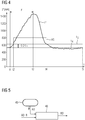
- FIG 4 shows an example of the time curve of the low-pass filtered motor current I * when door 3 is driven in opening direction O.
- no force F acts on side wall 16 of door 3, so that motor current I * corresponds to reference value I R .
- a force acts on the side wall 16 of the door 3 in the closing direction S.
- the recognition algorithm 43 sets an output signal AS active.
- the motor current I * increases until the force on the side wall 16 ceases at time t3.
- the motor current then decreases to I * and reaches the point in time t4 the limit value I G at which the output signal AS is reset again.
- the motor current I * then falls further, in order to then level itself back to the reference value I R at time t5.
- the signal AS is fed to the automatic control system 44.
- the automatic control system 44 When a release signal AS_R is present for “assisted stopping”, the automatic control system 44 generates a command ST for deleting the currently present drive order, which leads to the movement of the door 3 being stopped.
- a third analysis method that can be implemented by the analysis and evaluation unit 11 can aim at the fact that when the door 3 moves in one of the driving directions O, S and a permanent force is applied to the side surface 16 of the door 3 in this driving direction, the motor 2 is controlled in such a way that that the movement of the door 3 in the direction of travel takes place at a lower speed than during normal travel.
- This function can be referred to as “assisted drive” and enables the door 3 to move synchronously with a movement of an operator in the direction of travel.
- the analysis and evaluation unit 11 comprises according to FIG 5 a detection algorithm 45 and an associated automatic control system 46 for the "assisted driving" function.
- the detection algorithm 45 is also based on an analysis of the low-pass filtered motor current I *, in turn an evaluation of an actual value of the current I * based on the automatically learned reference value I R.
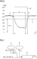
- FIG 6 shows an example of the time profile of the low-pass filtered motor current I * when door 3 in Opening direction O.
- the detection algorithm 45 sets an output signal AD active.
- the motor current I * continues to drop until the force F on the side wall 16 ceases at time t3.
- the motor current I * then rises again and, at time t4, reaches the limit value I G at which the output signal AD is reset again.
- the motor current I * then rises further in order to then level itself back to the reference value I R at time t5.
- the detection algorithm 45 can be flexibly adapted to different door systems with regard to its sensitivity.
- the signal AD of the automatic control 46 is supplied.
- a release signal AD_R for "assisted driving” is present, the automatic control system 46 generates a command RD for changing an existing driving order at normal speed to a driving order at reduced speed.
- the functions “pulse starting” and “assisted stopping” are combined with one another in the analysis and evaluation unit 11.
- the analysis and evaluation unit 11 has both the detection algorithm 41 for the “impulse start” and the detection algorithm 43 for the “assisted stopping” as well as in addition an automatic control system 47 is available for these combined functions.
- the automatic control system 47 can be activated via an extension signal "Supported stopping" IMP_R_ext in connection with the enable signal IMP_R for the "impulse start".
- the "Assisted stopping" function is a dynamic function that can be switched on and off while driving.
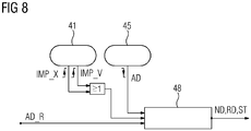
- the functions "impulse starting” and “assisted driving” are combined with one another in the analysis and evaluation unit 11.
- the analysis and evaluation unit 11 has both the recognition algorithm 41 for the "impulse starting” function and the recognition algorithm 45 for the "assisted driving” function, as well as an automatic control system 48 for these combined functions.
- the automatic control system 48 is activated via the release signal AD_R for the "assisted driving" function.
- the "Impulse start” function is first active and generates a command ND for a drive order at normal speed for door 3 in opening direction O. If the manual force in opening direction O continues continues, the "assisted driving” function becomes active and generates an output signal AD, whereupon the automatic control system 48 converts the command ND for the driving order ND at normal speed into a command RD for a driving order at reduced speed. As long as the manual force F continues in the opening direction O, the signal AD is also still active. As soon as but the manual force is not applied, the signal AD is reset. The automatic control system 48 thereupon generates a command ST for deleting the drive order, which leads to the door 3 stopping. A corresponding functionality works with a manual force F 'in the closing direction S.
- the analysis method described to determine the effect of a force in the direction of travel (i.e. a support force) or against the direction of travel (i.e. a counterforce) of a door or a door leaf by comparing the motor current (or intermediate circuit current) with a reference value that was automatically learned, for example when the door drive was started up and represents the current without the presence of a manual counterforce or support force, can be used in addition to sliding doors on all types of doors that can be moved by means of an electric drive, for example also on pivoting doors, revolving doors, folding doors and flap doors.
- the functions derived as a result of this analysis, such as "assisted driving" or "assisted braking” can also be used - possibly in a slightly adapted form - on all types of doors that can be moved by means of an electric drive.
Landscapes
- Power-Operated Mechanisms For Wings (AREA)
Description
Die Erfindung betrifft ein Verfahren zur Steuerung eines elektrischen Antriebs einer Tür oder eines Türflügels gemäß Patentanspruch 1 sowie eine Türsteuereinrichtung gemäß Patentanspruch 9.The invention relates to a method for controlling an electric drive of a door or a door leaf according to
Türsteuereinrichtungen dienen zur Steuerung und/oder Regelung zumindest eines elektrischen Antriebsmotors zum Öffnen bzw. Schließen wenigstens einer Tür oder eines Türflügels, insbesondere wenigstens einer Schiebetür oder eines Flügels einer Schiebetür.Door control devices serve to control and / or regulate at least one electric drive motor for opening or closing at least one door or one door leaf, in particular at least one sliding door or one leaf of a sliding door.
Schiebetüren finden sich vor allem in Aufzügen, auf Bahnsteigen zur Zutrittskontrolle zu Zügen, am Eingang von Gebäuden oder zum Personenschutz im industriellen Umfeld, z.B. an Werkzeugmaschinen.Sliding doors are mainly found in elevators, on platforms for access control to trains, at the entrance of buildings or for personal protection in an industrial environment, e.g. on machine tools.
Als elektrische Antriebsmotoren kommen beispielsweise Gleichstrommotoren oder neuerdings elektronisch kommutierte, bürstenlose, permanent erregte Synchronmotoren mit oder ohne einem nachgeschalteten Getriebe zum Einsatz.For example, direct current motors or, more recently, electronically commutated, brushless, permanently excited synchronous motors with or without a downstream gear are used as electric drive motors.
Beispiele für Türantriebe mit derartigen Türsteuereinrichtung sind in der
In zunehmendem Maße sind derartige Türsteuereinrichtungen in ein Automatisierungssystem eingebunden und über eine industrielle Kommunikationsverbindung (z.B. PROFIBUS, PROFINET) mit einer zentralen übergeordneten Steuerung verbunden.Door control devices of this type are increasingly being integrated into an automation system and connected to a central, higher-level controller via an industrial communication link (e.g. PROFIBUS, PROFINET).
Mittels des elektrischen Türantriebs ist eine Tür oder ein Türflügel in einer ersten Fahrrichtung (Schließrichtung) von einer geöffneten Position in eine geschlossene Position und umgekehrt in einer zweiten Fahrrichtung (Öffnungsrichtung) von der geschlossenen Position in die geöffnete Position bewegbar. Es sind dabei auch schon Fälle bekannt, bei denen der Antrieb durch manuelle (d.h. durch eine Hand ausgeübte) Krafteinwirkungen auf die Tür gesteuert wird.By means of the electric door drive, a door or a door leaf is in a first direction of travel (closing direction) from an open position to a closed position and conversely movable in a second direction of travel (opening direction) from the closed position to the open position. Cases are also known in which the drive is controlled by manual (that is, exerted by one hand) forces acting on the door.
So ist bei Drehtüren schon eine sogenannte "Push&Go"-Funktion bekannt. Bei einem Stillstand der Tür führt dabei ein kurzes manuelles Anschieben der Tür in Öffnungsrichtung (d.h. eine Krafteinwirkung senkrecht auf eine Seitenfläche der Tür in Drehrichtung der Tür) zu einem automatischen Öffnen der Tür und anschließendem selbsttätigen Schließen der Tür mit individuell einstellbarer Offenhaltezeit. Die Drehtüren weisen dabei aber an und für sich wenig Gewicht auf und wären an sich auch mühelos vollständig manuell zu öffnen. Die Funktion ist nur eine Komfortfunktion, die es beispielsweise ermöglicht, bei wenig Handfreiheit die Tür zu öffnen.A so-called "Push & Go" function is already known for revolving doors. When the door comes to a standstill, a short manual pushing of the door in the opening direction (i.e. a force acting vertically on a side surface of the door in the direction of rotation of the door) results in the door being opened automatically and the door subsequently closing automatically with an individually adjustable hold-open time. However, the revolving doors in and of themselves have little weight and could also be easily opened manually. The function is just a convenience function that makes it possible, for example, to open the door when there is little hand freedom.
Aus
Aus
Von Schiebetüren ist zudem eine "Hinderniserkennung" bekannt. Dabei führt bei einer Bewegung der Tür in Schließrichtung eine dauerhafte manuelle Krafteinwirkung auf eine vordere Stirnfläche der Tür in Schließrichtung zu einem Stoppen des Antriebs oder einer Umkehr der Bewegungsrichtung (Reversieren). Hierzu wird beispielweise auf eine Unterschreitung einer festgelegten Soll-Schließgeschwindigkeit und/oder Überschreiten eines maximalen Drehmomentes überwacht. Außerdem ist eine Impulsüberwachung des Inkrementalgebers möglich. In entsprechender Weise führt eine dauerhafte manuelle Krafteinwirkung auf eine vordere Stirnfläche der Tür in Öffnungsrichtung zu einem Stoppen des Antriebs.An "obstacle detection" is also known from sliding doors. When the door is moved in the closing direction, a permanent manual force on a front face of the door in the closing direction leads to a stop of the drive or a reversal of the direction of movement (reversing). For this purpose, monitoring is carried out, for example, for falling below a specified target closing speed and / or exceeding a maximum torque. Pulse monitoring of the incremental encoder is also possible. In a corresponding manner, a permanent manual force on a front face of the door in the opening direction stops the drive.
Gerade Schiebetüren in gewerblichen oder industriellen Gebäuden und Anlagen weisen ein hohes Gewicht von 300 kg und mehr auf. Aufgrund des hohen damit verbundenen Reibungswiderstandes ist ein manuelles Schieben der Tür nahezu unmöglich und es kommen deshalb Türantriebe zum Bewegen der Türen zum Einsatz. Über aufwendige Sensor- oder Eingabesysteme (z.B. über seitlich am Türrahmen angeordnete digitale Schalter) können manuell Fahraufträge abgeleitet und somit der Türantrieb gesteuert werden. Eine manuelle Steuerung ist dabei aber wegen der Größe der Türen und der Entfernungen zu den Eingabesystemen (z.B. Schaltern) jedoch schwierig. So hat im Fall einer großen Tür eine Person, die mit der sich öffnenden oder schließenden Tür mitgeht, Probleme, mit ihrer Hand ein Eingabesystem zu erreichen, das sich stationär in einem Türrahmen befindet. Zudem müssen bei einem derartigen Antrieb auch Personengefährdungen vermieden werden.Sliding doors in commercial or industrial buildings and systems in particular have a high weight of 300 kg and more. Due to the high frictional resistance associated with this, manual sliding of the door is almost impossible and door drives are therefore used to move the doors. Using complex sensor or input systems (e.g. digital switches on the side of the door frame), driving orders can be derived manually and the door drive can be controlled. However, manual control is difficult because of the size of the doors and the distance to the input systems (e.g. switches). In the case of a large door, for example, a person who walks along with the opening or closing door has problems reaching an input system with their hand that is stationary in a door frame. In addition, personal hazards must be avoided with such a drive.
Es ist deshalb Aufgabe vorliegender Erfindung, ein Verfahren anzugeben, mit dem unter Vermeidung von Personengefährdungen und ohne zusätzliche Eingabesysteme eine einfache Steuerung eines elektrischen Antriebs einer schweren Tür oder eines schweren Türflügels durch manuelle Krafteinwirkungen möglich ist.It is therefore the object of the present invention to provide a method with which a simple control of an electric drive of a heavy door or a heavy door while avoiding personal hazards and without additional input systems heavy door leaf is possible by manual force.
Die Lösung dieser Aufgabe gelingt durch ein Verfahren mit dem Merkmalen des Patentanspruchs 1 und eine Türsteuereinrichtung mit den Merkmalen des Anspruchs 9. Vorteilhafte Ausgestaltungen des Verfahrens sind Gegenstand der Ansprüche 2 bis 8 und vorteilhafte Ausgestaltungen der Türsteuereinrichtung sind Gegenstand der Ansprüche 10 bis 15.This object is achieved by a method with the features of
Erfindungsgemäß wird zum Bewegen der Tür oder des Türflügels der elektrische Antrieb der Tür oder des Türflügels durch manuelle Krafteinwirkungen, die in einer der Fahrrichtungen auf die Seitenfläche der Tür oder des Türflügels oder ein darauf angeordnetes Bauteil (z.B. einen Türgriff) wirken, gesteuert. Dabei liegt der Gedanke zugrunde, die ohnehin vorhandene Seitenfläche der Tür selbst als eine Art "Eingabesystem" für die Steuerung des Antriebs und damit der Bewegung der Tür zu nutzen, so dass kein zusätzliches Eingabesystem notwendig ist. Aufgrund der üblicherweise großen Fläche der Seitenfläche ist für eine Bedienperson eine gute Erreichbarkeit mit der Hand gegeben, gerade auch wenn sich die Bedienperson mit der sich öffnenden oder schließenden Tür mitbewegt. Da durch die Seitenfläche - im Gegensatz zu einer Stirnfläche der Tür - keine Quetschgefahr für eine Bedienperson ausgeht, kann auch eine Personengefährdung vermieden werden. Durch direkte manuelle Krafteinwirkung in der oder den Fahrrichtungen kann auch eine besonders intuitive und somit einfache Steuerung des Antriebs und somit der Bewegung einer schweren Tür erfolgen. Dabei kann durch die manuellen Krafteinwirkungen entweder nur eine Steuerung eines Teils der Bewegungen der Tür (z.B. nur ein Anfahren oder ein Anhalten der Tür) oder auch vorzugsweise eine Steuerung sämtlicher Bewegungsabläufe (z.B. auch Geschwindigkeitsänderungen, Reversierfunktionen) ermöglicht werden.According to the invention, to move the door or the door leaf, the electric drive of the door or the door leaf is controlled by manual forces acting in one of the directions of travel on the side surface of the door or the door leaf or a component arranged thereon (e.g. a door handle). This is based on the idea of using the already existing side surface of the door itself as a type of "input system" for controlling the drive and thus the movement of the door, so that no additional input system is necessary. Due to the usually large area of the side surface, the operator can easily reach it by hand, especially when the operator moves with the opening or closing door. Since the side face - in contrast to an end face of the door - does not pose a risk of crushing for an operator, a risk to persons can also be avoided. A particularly intuitive and thus simple control of the drive and thus of the movement of a heavy door can also take place through direct manual force action in the direction or directions of travel. The manual force effects can either only control part of the door's movements (e.g. only starting or stopping the door) or preferably all movement sequences (e.g. also speed changes, reversing functions).
Weiterhin werden für die Steuerung des Antriebs eine Dauer und/oder Richtung und/oder Stärke der manuellen Krafteinwirkungen ermittelt. Diese Informationen können entweder in einer Türsteuerung selbst oder in einer dieser übergeordneten Steuerung flexibel miteinander verknüpft und daraus je nach Anwendungsfall unterschiedlichste Sollvorgaben für den Antrieb abgeleitet werden, beispielsweise Fahraufträge erteilt, gelöscht, unterbrochen oder abgeändert werden. Durch unterschiedliche Parametrierungen bei der Ermittlung dieser Werte können unterschiedliche Empfindlichkeiten eingestellt und somit eine Anpassung der Steuerung an unterschiedliche Türen, Antriebe, Gewichte, Gummilippen, etc. erfolgen.Furthermore, a duration and / or direction and / or strength of the manual force effects are used to control the drive determined. This information can be flexibly linked with one another either in a door control itself or in one of these higher-level controls and, depending on the application, a wide variety of target specifications for the drive can be derived, for example, travel orders can be issued, deleted, interrupted or changed. By different parameterizations when determining these values, different sensitivities can be set and thus the control can be adapted to different doors, drives, weights, rubber lips, etc.
Die Dauer und/oder Richtung und/oder Stärke der manuellen Krafteinwirkungen kann bei einer Bewegung des Antriebs besonders einfach und ohne zusätzliche aufwendige Sensorsysteme mittels eines Einspeisestromes des Antriebs oder eines Zwischenkreisstromes einer Strom- oder Spannungsversorgung des Antriebs ermittelt werden. Aus den ermittelten Werten der Dauer und/oder Richtung und/oder Stärke der manuellen Krafteinwirkung kann eine Türsteuereinrichtung selbst einen Status des Antriebs ableiten und in Abhängigkeit davon Reaktionen ableiten. Der Status des Antriebs kann aber auch an eine übergeordnete Steuerungseinrichtung gemeldet werden, die dann durch entsprechende Vorgaben an eine Türsteuereinrichtung eine Reaktion auslöst.The duration and / or direction and / or strength of the manual force effects can be determined particularly easily and without additional complex sensor systems by means of a feed current of the drive or an intermediate circuit current of a current or voltage supply of the drive when the drive is moving. A door control device itself can derive a status of the drive from the determined values of the duration and / or direction and / or strength of the manual force action and derive responses as a function thereof. The status of the drive can also be reported to a higher-level control device, which then triggers a reaction by corresponding specifications to a door control device.
Die Ermittlung der Dauer und/oder Richtung und/oder Stärke der Krafteinwirkung kann hierbei besonders einfach dadurch erfolgen, dass ein Aktualwert des Einspeisestromes oder Zwischenkreisstromes mit einem, vorzugsweise automatisch eingelernten, Referenzwert verglichen wird. Der Referenzwert kann beispielsweise bei der Inbetriebnahme durch eine Lernfahrt für den gesamten Verfahrweg ermittelt werden und den Aktualwert des Einspeisestromes oder Zwischenkreisstromes ohne externe Krafteinwirkungen auf die Tür repräsentieren.The determination of the duration and / or direction and / or strength of the force action can take place particularly simply by comparing an actual value of the feed current or intermediate circuit current with a reference value that is preferably automatically learned. The reference value can, for example, be determined during commissioning by a learning run for the entire travel distance and represent the actual value of the feed current or intermediate circuit current without external forces acting on the door.
Bei keiner Bewegung des Antriebs kann die Dauer und/oder Richtung und/oder Stärke der manuellen Krafteinwirkung besonders einfach mittels eines durch die Krafteinwirkungen verursachten inkrementellen Wegs und/oder einer durch die Krafteinwirkungen verursachten Geschwindigkeit des Antriebs oder der Tür oder des Türflügels ermittelt werden.If the drive is not moving, the duration and / or direction and / or strength of the manual force can be determined particularly easily by means of an incremental path caused by the force and / or a speed of the drive or the door or door leaf caused by the force.
Eine Generierung eines Fahrauftrags zum Öffnen oder Schließen der Tür oder des Türflügels kann auf einfache und bedienerfreundliche Weise dadurch erfolgen, dass bei einer Bewegungslosigkeit der Tür oder des Türflügels und einer impulsförmigen manuellen Krafteinwirkung in einer der Fahrrichtungen der Antrieb derart angesteuert wird, dass sich die Tür oder der Türflügel in dieser Fahrrichtung bewegt.A drive order to open or close the door or the door leaf can be generated in a simple and user-friendly manner in that, when the door or the door leaf is motionless and a pulsed manual force is exerted in one of the directions of travel, the drive is controlled in such a way that the door moves or the door leaf moves in this direction of travel.
Bei einer Bewegung der Tür oder des Türflügels in einer der Fahrrichtungen und einer ruckartigen Krafteinwirkung auf die Seitenfläche der Tür oder des Türflügels entgegen dieser Fahrrichtung kann der Antrieb dann beispielsweise derart angesteuert werden, dass die Bewegung der Tür oder des Türflügels in der Fahrrichtung gestoppt wird. Dies kann dann auch ein Löschen eines Fahrauftrages bewirken.If the door or the door leaf moves in one of the directions of travel and a jerky force is applied to the side surface of the door or the door leaf against this direction of travel, the drive can then, for example, be controlled in such a way that the movement of the door or the door leaf in the direction of travel is stopped. This can then also cause a travel order to be deleted.
Bei einer Bewegung der Tür oder des Türflügels in einer der Fahrrichtungen und einer dauerhaften Krafteinwirkung auf die Seitenfläche der Tür in dieser Fahrrichtung : wird der Antrieb erfindungsgemäß derart angesteuert dass die Bewegung der Tür oder des Türflügels in der Fahrrichtung mit einer vordefinierten, insbesondere reduzierten, Geschwindigkeit erfolgt. Damit kein eine Aufrechterhaltung oder Abänderung eines vorherigen Fahrauftrags verbunden sein. Wenn bei einem bestehenden Fahrauftrag diese dauerhafte Krafteinwirkung entfällt, kann dies wiederum eine Löschung oder Unterbrechung eines Fahrauftrags bewirken.When the door or the door leaf moves in one of the directions of travel and a permanent force is exerted on the Side surface of the door in this direction of travel: the drive is controlled according to the invention in such a way that the movement of the door or the door leaf in the direction of travel takes place at a predefined, in particular reduced, speed. This does not involve maintaining or changing a previous travel order. If this permanent force does not apply to an existing transport order, this can in turn cause a deletion or interruption of a transport order.
Eine erfindungsgemäße Türsteuerungseinrichtung für einen elektrischen Antrieb einer Tür oder eines Türflügels, wobei die Tür oder der Türflügel mittels des Antriebs in einer ersten Fahrrichtung (Schließrichtung) von einer geöffneten Position in eine geschlossene Position und umgekehrt in einer zweiten Fahrrichtung (Öffnungsrichtung) von der geschlossenen Position in die geöffnete Position bewegbar ist, und wobei die Tür oder der Türflügel zumindest eine in den beiden Fahrrichtungen verlaufende Seitenfläche aufweist, ist derart ausgebildet, dass sie zum Bewegen der Tür oder des Türflügels in zumindest einer der beiden Fahrrichtungen den Antrieb in Abhängigkeit von manuellen Krafteinwirkungen, die in einer der Fahrrichtungen auf die Seitenfläche der Tür oder des Türflügels oder ein darauf angeordnetes Bauteil (z.B. Türgriff) wirken, steuert. Die Türsteuereinrichtung ist derart ausgebildet, dass bei einer Bewegung der Tür in diese Fahrrichtung und einer dauerhaften manuellen Krafteinwirkung auf die Tür in diese Fahrrichtung der Antrieb derart angesteuert wird, dass die Bewegung der Tür in diese Fahrrichtung mit einer vordefinierten Geschwindigkeit erfolgt.A door control device according to the invention for an electric drive of a door or a door leaf, the door or the door leaf by means of the drive in a first direction of travel (closing direction) from an open position to a closed position and vice versa in a second direction of travel (opening direction) from the closed position is movable into the open position, and wherein the door or the door leaf has at least one side surface running in the two directions of travel, is designed such that it uses the drive to move the door or the door leaf in at least one of the two directions of travel as a function of manual forces , which act in one of the directions of travel on the side surface of the door or the door leaf or a component arranged on it (e.g. door handle) controls. The door control device is designed such that when the door is moved in this direction of travel and there is a permanent manual force on the door in this direction, the drive is controlled in such a way that the door moves in this direction at a predefined speed.
Vorteilhafte Ausgestaltungen der Türsteuereinrichtung sind Gegenstand der Ansprüche 10 bis 15. Die für das erfindungsgemäße Verfahren und seine vorteilhaften Ausgestaltungen genannten Überlegungen und Vorteile gelten entsprechend für die erfindungsgemäße Türsteuereinrichtung bzw. deren jeweils korrespondierende Ausgestaltungen.Advantageous refinements of the door control device are the subject matter of
Die Erfindung sowie weitere vorteilhafte Ausgestaltungen der Erfindung gemäß Merkmalen der Unteransprüche werden im Folgenden anhand von Ausführungsbeispielen in den Figuren näher erläutert; darin zeigen:
- FIG 1
- einen Türantrieb mit einer erfindungsgemäßen Türsteuereinrichtung,
- FIG 2
- eine Analyse- und Auswerteeinheit für eine Funktion "Impuls-Anfahren",
- FIG 3
- eine Analyse- und Auswerteeinheit für eine Funktion "Unterstütztes Anhalten",
- FIG 4
- einen Verlauf eines Motorstromes über der Zeit zur Ermittlung einer manuellen Krafteinwirkung für die Funktion "Unterstütztes Anhalten",
- FIG 5
- eine Analyse- und Auswerteeinheit für eine Funktion "Unterstütztes Fahren",
- FIG 6
- einen Verlauf eines Motorstromes über der Zeit zur Ermittlung einer manuellen Krafteinwirkung für die Funktion "Unterstütztes Fahren",
- FIG 7
- eine Analyse- und Auswerteeinheit für eine Kombination der Funktionen "Impuls-Anfahren" und "Unterstütztes Anhalten" und
- FIG 8
- eine Analyse- und Auswerteeinheit für eine Kombination der Funktionen "Impuls-Anfahren" und "Unterstütztes Fahren".
- FIG 1
- a door drive with a door control device according to the invention,
- FIG 2
- an analysis and evaluation unit for a "pulse approach" function,
- FIG 3
- an analysis and evaluation unit for an "assisted stopping" function,
- FIG 4
- a course of a motor current over time to determine a manual force effect for the "Assisted stopping" function,
- FIG 5
- an analysis and evaluation unit for an "assisted driving" function,
- FIG 6
- a course of a motor current over time to determine a manual force effect for the "assisted driving" function,
- FIG 7
- an analysis and evaluation unit for a combination of the functions "impulse starting" and "assisted stopping" and
- FIG 8
- an analysis and evaluation unit for a combination of the "impulse starting" and "assisted driving" functions.
Eine in
Der elektrische Antriebsmotor 2 ist vorzugsweise ein elektronisch kommutierter, bürstenloser, permanenterregter Synchronmotor.The
Die Türsteuereinrichtung 1 bildet zusammen mit dem Motor 2 einen Türantrieb 9.The
Die Türsteuereinrichtung 1 umfasst einen Leistungsteil 5 zur Spannungs-/Stromversorgung des Motors 2 und einen Steuerteil 10 zur Steuerung und/oder Regelung des Leistungsteils 5 und somit des Motors 2.The
Der Leistungsteil 5 umfasst einen Gleichrichter 6 und eine Kommutierungsschaltung 7 für den Motor 2. Der Gleichrichter 6 und die Kommutierungsschaltung 7 sind über einen Zwischenkreis 8 miteinander verbunden. Der Gleichrichter 6 kann eingangsseitig - ggf. über einen Netztransformator - mit einem Spannungsversorgungsnetz verbunden sein (nicht dargestellt).The
Der Steuerteil 10 umfasst ein Mikrocontrollersystem mit einem nicht näher dargestellten Mikrocontroller und einem Datenspeicher.The
Die Türsteuereinrichtung 1 ist in einem Gehäuse 20 untergebracht und bildet somit ein kompaktes Gerät.The
Das Gehäuse 20 weist eine Kommunikationsschnittstelle 23 zur Kommunikation mit einem geräte-externen industriellen Kommunikationssystem 30 (z.B. einem Datenbus oder -netz wie z.B. PROFIBUS oder PROFINET) auf.The
An das Kommunikationssystem 30 können noch weitere Türantriebe 9 sowie eine übergeordnete Steuerung 31 für die Türantriebe 9 angekoppelt sein. Die übergeordnete Steuerung 31, das Kommunikationssystem 30 sowie die Türantriebe 9 bilden ein Automatisierungssystem 35. Die übergeordnete Steuerung 31 ist über das Kommunikationssystem 30 mit den Türsteuereinrichtungen 1 über deren jeweilige Schnittstelle 23 zu deren Steuerung verbunden.Further door drives 9 and a higher-
Der Motor 2 treibt über seine Abtriebswelle 4 eine Umlenkrolle 12 an, die formschlüssig einen Zahnriemen 13 antreibt, an dem die Tür 3 über eine Halterung 14 befestigt ist. Der Zahnriemen 13 ist dabei über eine zweite Umlenkrolle 15 geführt, die entweder nicht angetrieben ist, oder - beispielsweise bei besonders schweren Türen - ebenfalls von einem Motor angetrieben wird, der mit dem Motor 2 synchronisiert ist. Alternativ kann anstatt des Zahnriemens 13 auch eine Zahnstange vorgesehen sein.The
Die Tür 3 ist mittels des Motors 2 in einer ersten Fahrrichtung (Schließrichtung), die in
Die Tür 3 weist zwei in den beiden Fahrrichtungen S, O verlaufende Seitenflächen auf, von denen in
Zum Bewegen der Tür 3 ist der Motor 2 in zumindest einer der beiden Fahrrichtungen S oder O durch manuelle Krafteinwirkungen, die in einer der Fahrrichtungen S, O auf die Seitenfläche 16 der Tür 3 oder ein darauf angeordnetes Bauteil (z.B. einen Türgriff 19) wirken, steuerbar.To move the
Hierzu werden durch eine Analyse- und Auswerteinheit 11 eine Dauer, Richtung und Stärke der manuellen Krafteinwirkungen auf die Seitenfläche 16 ermittelt.For this purpose, an analysis and
Dies erfolgt bei einer Bewegung der Tür - wie im Zusammenhang mit
Bei keiner Bewegung der Tür kann dies durch Ermittlung eines durch eine manuelle Krafteinwirkung verursachten inkrementellen Wegs X (bei leichten Türen) oder einer Geschwindigkeit V (bei schweren Türen) der Abtriebswelle 4 mit Hilfe eines hiermit gekoppelten Inkrementalgebers 21 erfolgen. Alternativ kann der Inkrementalgeber 21 hierzu auch mit einem Rotor des Motors 2, dem Zahnriemen 13 oder einer der Umlenkrollen 12, 15 gekoppelt sein.If the door is not moving, this can be done by determining an incremental path X (for light doors) or a speed V (for heavy doors) of the
Durch eine Analyse der ermittelten Dauer, Richtung und Stärke der manuellen Krafteinwirkungen auf die Seitenfläche 16 kann auf vordefinierte Bewegungszustände der Tür bzw. Betriebszustände des Antriebs 9 geschlossen werden und in Abhängigkeit davon vordefinierte Reaktionen (z.B. Auslösen, Löschen, Unterbrechung, Änderung von Fahraufträgen, d.h. vordefinierten Bewegungsprofilen für die Tür 3) ausgelöst werden. Diese Analyse kann auf Parametern beruhen, die in der Analyse- und Auswerteeinheit 11 individuell einstellbar sind, um somit hinsichtlich der Empfindlichkeit der Analyse und der Reaktionen eine Anpassung an unterschiedliche Türsysteme zu ermöglichen.By analyzing the determined duration, direction and strength of the manual force effects on the
Zur Analyse und Ableitung von Vorgaben für die Steuerung des Motors 2 kann sich - wie dargestellt - die Analyse- und Auswerteeinheit 11 entweder in dem Steuerteil 10 der Türsteuereinrichtung 1 oder alternativ auch in der übergeordneten Steuereinrichtung 31 befinden. In letzterem Fall werden die von der Türsteuereinrichtung 1 ermittelten Werte für den Strom I oder I' sowie zum inkrementellen Weg X oder der Geschwindigkeit V in Form von Statusinformationen über die Schnittstelle 23 und das Kommunikationssystem 30 an die übergeordneten Steuereinrichtung 31 übertragen bzw. umgekehrt Steuervorgaben der übergeordneten Steuereinrichtung 31 an die Türsteuereinrichtung 1 übertragen.To analyze and derive specifications for the control of the
Die Analyse- und Auswerteeinheit 11 kann hierzu eine oder mehrere Erkennungsalgorithmen und Steuerautomatiken aufweisen, die beispielsweise in Form von einem oder mehreren ausführbaren Programmen in einem Datenspeicher der Analyse- und Auswerteeinheit 11 gespeichert sind und durch eine Prozessor der Analyse- und Auswerteeinheit 11 zur Ausführung gebracht werden können.For this purpose, the analysis and
Ein erstes durch die Analyse- und Auswerteeinheit 11 realisierbares Analyseverfahren kann darauf hinzielen, dass bei bewegungsloser Tür 3 und einer impulsförmigen manuellen Krafteinwirkung F oder F' auf die Seitenfläche 16 in einer der Fahrrichtungen S, O der Motor 2 derart angesteuert wird, dass sich die Tür 3 in dieser Fahrrichtung O, S bewegt. Diese Funktion kann als Impuls-Anfahren ("Impuls-Drive") bezeichnet werden und ermöglicht ein Auffahren einer schweren Tür durch leichtes Drücken an der Tür oder einem Türgriff in einer Fahrrichtung S bzw. O.A first analysis method that can be implemented by the analysis and
Die Analyse- und Auswerteeinheit 11 weist hierzu gemäß
Wenn der Erkennungsalgorithmus 41 durch Analyse des mit Hilfe des Inkrementalgebers 21 erfassten inkrementellen Weges X (bei leichten Türen) oder der Geschwindigkeit V (bei schweren Türen) der Abtriebswelle 4 eine impulsförmige Krafteinwirkung in Öffnungsrichtung O oder Schließrichtung S erkennt, wird von diesem entweder ein Signal IMP_V oder IMP_X erzeugt. Diese beiden Signale werden logisch mit einer Oder-Schaltung verknüpft und der Steuerautomatik 42 zugeführt. Die Steuerautomatik 42 erzeugt bei Vorliegen eines Freigabesignals IMP_R einen Fahrauftrag für das Bewegen der Tür 3 in der Richtung der Krafteinwirkung F auf die Seitenfläche 16 bzw. der mittels des Inkrementalgebers 21 ermittelten Drehrichtung der Abtriebswelle 4, d.h. je nach Richtung der Krafteinwirkung F entweder in Öffnungsrichtung O oder in Schließrichtung S.If the
Ein zweites durch die Analyse- und Auswerteeinheit 11 realisierbares Analyseverfahren kann darauf hinzielen, dass bei einer Bewegung der Tür 3 in einer der Fahrrichtungen S, O und einer ruckartigen Krafteinwirkung auf die Seitenfläche 16 der Tür 3 entgegen dieser Fahrrichtung der Motor 2 derart angesteuert wird, dass die Bewegung der Tür 2 in der Fahrrichtung gestoppt wird. Diese Funktion kann als "Unterstütztes Anhalten" ("Assisted Stop") bezeichnet werden und ermöglicht ein manuelles Anhalten der Tür 3 durch einen leichten Ruck an der Tür entgegen der Fahrtrichtung.A second analysis method that can be implemented by the analysis and
Die Analyse- und Auswerteeinheit 11 umfasst hierzu gemäß
Der Erkennungsalgorithmus 43 basiert auf einer Analyse des tiefpassgefilterten Einspeisestromes I des Motors 2, im Folgenden mit "I*" bezeichnet. Dieser spiegelt die Antriebskraft des Motors 2 wieder. Das zugrunde liegende Verfahren bewertet einen Aktualwert des Stroms I* bezogen auf einen automatisch eingelernten Referenzwert IR. Dieser Referenzwert IR wird in einer dem Fachmann geläufigen Weise bei der Inbetriebnahme des Türantriebs 9 durch eine Lernfahrt für den gesamten Verfahrweg der Tür 3 ermittelt. Dies erfolgt separat für die Öffnungs- und Schließrichtung O bzw. S.The
Wie in
Ein drittes durch die Analyse- und Auswerteeinheit 11 realisierbares Analyseverfahren kann darauf hinzielen, dass bei einer Bewegung der Tür 3 in einer der Fahrrichtungen O, S und einer dauerhaften Krafteinwirkung auf die Seitenfläche 16 der Tür 3 in dieser Fahrrichtung der Motor 2 derart angesteuert wird, dass die Bewegung der Tür 3 in der Fahrrichtung mit einer niedrigeren Geschwindigkeit als bei einer Normalfahrt erfolgt. Diese Funktion kann als "Unterstütztes Fahren" ("Assisted Drive") bezeichnet werden und ermöglicht eine Bewegung der Tür 3 synchron mit einer Bewegung einer Bedienperson in der Fahrrichtung.A third analysis method that can be implemented by the analysis and
Die Analyse- und Auswerteeinheit 11 umfasst hierzu gemäß
Der Erkennungsalgorithmus 45 basiert ebenfalls auf einer Analyse des tiefpassgefilterten Motorstromes I*, und zwar wiederum einer Bewertung eines Aktualwerts des Stroms I* bezogen auf den automatisch eingelernten Referenzwert IR.The
Wie in
Die verschiedenen Analyseverfahren und die damit verbundenen Funktionen wie z.B. "Impuls-Anfahren", "Unterstütztes Bremsen" oder "Unterstütztes Fahren" können dabei auch flexibel miteinander kombiniert werden, um wiederum weitergehende Funktionalitäten für eine manuelle Steuerung des Motors 2 und somit der Bewegungen der Tür 3 zu ermöglichen.The various analysis methods and the associated functions such as "Impulse starting", "assisted braking" or "assisted driving" can also be flexibly combined with one another in order to enable further functionalities for manual control of the
In Fall von
Ist das Erweiterungssignal IMP_R_ext aktiv, arbeitet die Steuerautomatik 47 im langsamen Fahrprofil und es wird ein Befehl RD für einen Fahrauftrag mit reduzierter Geschwindigkeit erzeugt. Sobald der Erkennungsalgorithmus 43 durch Setzen des Signals AS eine Gegenkraft signalisiert, wird durch die Steuerautomatik 47 durch einen Befehl ST der aktive Fahrauftrag gelöscht. Die Funktion "Unterstütztes Anhalten" ist hierbei eine dynamische Funktion, die während der Fahrt zu- und abgeschaltet werden kann.If the expansion signal IMP_R_ext is active, the
In Fall von
Bei einer impulsförmigen manuellen Krafteinwirkung F in Öffnungsrichtung O auf die Seitenwand 16 wird zuerst die Funktion "Impuls-Anfahren" aktiv und erzeugt einen Befehl ND für einen Fahrauftrag mit normaler Geschwindigkeit für die Tür 3 in Öffnungsrichtung O. Wenn die manuelle Krafteinwirkung in Öffnungsrichtung O weiter anhält, wird die Funktion "Unterstützte Fahren" aktiv und erzeugt ein Ausgangssignal AD, woraufhin die Steuerautomatik 48 den Befehl ND für den Fahrauftrag ND mit normaler Geschwindigkeit in einen Befehl RD für einen Fahrauftrag mit reduzierter Geschwindigkeit umwandelt. Solange die manuelle Krafteinwirkung F in Öffnungsrichtung O weiter anhält ist auch das Signal AD weiterhin aktiv. Sobald aber die manuelle Krafteinwirkung entfällt, wird das Signal AD zurückgesetzt. Die Steuerautomatik 48 erzeugt daraufhin einen Befehl ST für ein Löschen des Fahrauftrags, was zu einem Anhalten der Tür 3 führt. Eine entsprechende Funktionalität wirkt bei einer manuellen Krafteinwirkung F' in Schließrichtung S.In the case of a pulsed manual force F in opening direction O on the
Das im Zusammenhang mit
Claims (15)
- Method for controlling an electrical drive (2) of a door (3) or a door wing, wherein the door (3) or the door wing can be moved by means of the drive (2) in a first direction of travel (S) from an opened position into a closed position and conversely in a second direction of travel (O) from the closed position into the opened position,
wherein in order to move the door or the door wing in at least one of the two directions of travel, the drive can be controlled by means of manual force effects (F) on the door (3) or the door wing, and
wherein the door (2) or the door wing has at least one side surface (16) which runs in the two directions of travel,
wherein in order to move the door (3) or the door wing, the drive (2) is controlled by means of manual force effects (F), which, in one of the directions of travel (S, O), act on the side surface (16) of the door (3) or the door wing or a component (19) arranged thereupon,
characterised in that with a movement of the door (3) or the door wing in one of the directions of travel (S, O) and a continuous force effect (F) on the side surface (16) of the door (3) or the door wing in this direction of travel (S, O), the drive (2) is controlled so that the movement of the door (2) or the door wing in the direction of travel (S, O) takes place with a predefined speed. - Method according to claim 1, characterised in that a duration and/or direction and/or intensity of the manual force effects (F) is determined for the controller of the drive (2).
- Method according to claim 2, characterised in that with a movement of the drive (2), the duration and/or direction and/or intensity of the manual force effects (F) are determined by means of a feeding current (I) or an intermediate circuit current (I') of a voltage or power supply (5) of the drive (2).
- Method according to claim 3, characterised in that to determine the duration and/or direction and/or intensity of the force effects (F), a current value of the feeding current (I) or intermediate circuit current is compared with a reference value which is preferably automatically taught.
- Method according to one of claims 2 to 4, characterised in that with no movement of the drive (2), the duration and/or direction and/or intensity of the manual force effects (F) are determined by means of an incremental path caused by the force effects (F) and/or a speed of the drive (2) or the door (3) caused by the force effects (F).
- Method according to one of the preceding claims, characterised in that with a motionless door (3) and a pulsed manual force effect (F) in one of the directions of travel (S, O), the drive (2) is controlled so that the door (3) moves in this direction of travel (S, 0).
- Method according to one of the preceding claims, characterised in that with a movement of the door (3) in one of the directions of travel (S, O) and a jerky force effect (F) on the door counter to this direction of travel (S, O), the drive (2) is controlled so that the movement of the door (3) in the direction of travel (S, O) is stopped.
- Method according to one of the preceding claims, wherein in one of the directions of travel (S, O) the manual force effects (F) act on the side surface (16) of the door (3).
- Door control facility (1) for an electrical drive (2) of a door (3) or a door wing, wherein the door (3) or the door wing can be moved by means of the drive (2) in a first direction of travel (S) from an opened position into a closed position and conversely in a second direction of travel (O) from the closed position into the opened position,
wherein the door (3) or the door wing has at least one side surface (16) which runs in the two directions of travel (S, O), wherein the door control facility (1) is embodied so that in order to move the door (3) or the door wing in at least one of the two directions of travel (S, O) it controls the drive (2) as a function of manual force effects, which in one of the directions of travel (S, O) act on the side surface (16) of the door (3) or the door wing or a component (19) arranged thereupon,
characterised in that the door control facility (1) is embodied so that with a movement of the door (3) or the door wing in one of the directions of travel (S, O) and a continuous force effect (F) on the side surface (16) of the door (3) or the door wing in this direction of travel (S, O) it controls the drive (2) so that the movement of the door (2) or the door wing in the direction of travel (S, O) is carried out with a predefined speed. - Door control facility (1) according to claim 9, characterised by at least one analysis and evaluation unit (11) for determining a duration and/or direction and/or intensity of the manual force effects (F).
- Door control facility (1) according to claim 10, characterised in that the analysis and evaluation unit (11) is connected to a sensor (22) for acquiring a feeding current (I) or an intermediate circuit current for the drive (2) and is embodied so that with a movement of the drive (2) it determines the duration and/or direction and/or intensity of the manual force effects (F) by comparing a current value of the feeding current (I) or intermediate circuit current with a reference value which is preferably automatically taught.
- Door control facility (1) according to claim 10, characterised in that the analysis and evaluation unit (11) is connected to an incremental sensor (21) for acquiring an incremental path and/or a speed of the drive (2) or the door (3) and is embodied so that with no movement of the drive (2), it determines the duration and/or direction and/or intensity of the manual force effects by means of an incremental path caused by the force effects and/or a speed of the drive (2) or the door (3) caused by the force effects.
- Door control facility (1) according to one of claims 9 to 12, characterised in that it is embodied so that with a movement of the door (3) in one of the directions of travel (S, O) and a jerky force effect (F) on the side surface (16) of the door counter to this direction of travel (S, O), it controls the drive (2) so that the movement of the door (3) stops in the direction of travel (S, 0).
- Door control facility (1) according to one of claims 9 to 13, wherein in one of the directions of travel (S, O) the manual force effects (F) act on the side surface (16) of the door (3).
- Door control facility (1) according to one of claims 9 to 14, characterised in that it is embodied so that with no movement of the door (3) and a pulsed manual force effect (F) in one of the directions of travel (S, O), it controls the drive (2) so that the door (3) moves in this direction of travel (S, O).
Applications Claiming Priority (2)
| Application Number | Priority Date | Filing Date | Title |
|---|---|---|---|
| DE102013224148.8A DE102013224148A1 (en) | 2013-11-26 | 2013-11-26 | Method for controlling an electric drive of a door or a door leaf and door control device |
| PCT/EP2014/073507 WO2015078660A1 (en) | 2013-11-26 | 2014-11-03 | Method for controlling an electric drive of a door or door leaf and a door control device |
Publications (2)
| Publication Number | Publication Date |
|---|---|
| EP3044397A1 EP3044397A1 (en) | 2016-07-20 |
| EP3044397B1 true EP3044397B1 (en) | 2020-12-30 |
Family
ID=51894009
Family Applications (1)
| Application Number | Title | Priority Date | Filing Date |
|---|---|---|---|
| EP14796463.9A Active EP3044397B1 (en) | 2013-11-26 | 2014-11-03 | Method for controlling a electrical drive of a door or door wing and door control device |
Country Status (3)
| Country | Link |
|---|---|
| EP (1) | EP3044397B1 (en) |
| DE (1) | DE102013224148A1 (en) |
| WO (1) | WO2015078660A1 (en) |
Families Citing this family (6)
| Publication number | Priority date | Publication date | Assignee | Title |
|---|---|---|---|---|
| DE102016205367A1 (en) | 2016-03-31 | 2017-10-05 | Meiko Maschinenbau Gmbh & Co. Kg | Cleaning device and method for cleaning items to be cleaned |
| DE102019107187A1 (en) * | 2019-03-20 | 2020-09-24 | Brose Fahrzeugteile Se & Co. Kommanditgesellschaft, Bamberg | Control system for controlling a drive arrangement |
| DE102020125098A1 (en) * | 2020-09-25 | 2022-03-31 | Dormakaba Deutschland Gmbh | Method for pivoting a wing with a drive device and drive device for pivoting a wing |
| DE102021204691A1 (en) * | 2021-05-10 | 2022-11-10 | Geze Gmbh | Drive for a door |
| CN114622500B (en) * | 2022-01-27 | 2024-01-16 | 浙江大华技术股份有限公司 | Gate wing steering learning method, system, gate, computer equipment and storage medium |
| DE102023210163A1 (en) * | 2023-10-17 | 2025-04-17 | Geze Gmbh | door system |
Family Cites Families (6)
| Publication number | Priority date | Publication date | Assignee | Title |
|---|---|---|---|---|
| JPH10252349A (en) * | 1997-03-11 | 1998-09-22 | Asmo Co Ltd | Vehicle door opening and closing device |
| DE19956076A1 (en) | 1999-11-22 | 2001-05-31 | Siemens Ag | Drive device for elevator doors |
| DE202004017100U1 (en) * | 2004-10-29 | 2005-03-03 | Gretsch-Unitas GmbH Baubeschläge | Method for operating sliding door installations has mobile door section attached to driven mounting which is manually or automatically controlled |
| DE102006040232A1 (en) | 2006-08-28 | 2008-03-13 | Siemens Ag | Door drive for an automatic door |
| DE502007002673D1 (en) * | 2007-03-12 | 2010-03-11 | Delphi Tech Inc | Door operating procedures |
| DE102011004019B4 (en) | 2011-02-14 | 2015-02-12 | Siemens Aktiengesellschaft | Electrically powered door |
-
2013
- 2013-11-26 DE DE102013224148.8A patent/DE102013224148A1/en not_active Ceased
-
2014
- 2014-11-03 WO PCT/EP2014/073507 patent/WO2015078660A1/en not_active Ceased
- 2014-11-03 EP EP14796463.9A patent/EP3044397B1/en active Active
Non-Patent Citations (1)
| Title |
|---|
| None * |
Also Published As
| Publication number | Publication date |
|---|---|
| EP3044397A1 (en) | 2016-07-20 |
| WO2015078660A1 (en) | 2015-06-04 |
| DE102013224148A1 (en) | 2015-05-28 |
Similar Documents
| Publication | Publication Date | Title |
|---|---|---|
| EP3044397B1 (en) | Method for controlling a electrical drive of a door or door wing and door control device | |
| EP2653642B1 (en) | Method for operating a folding system and folding system | |
| EP2704925B1 (en) | Method for controlling a closure element arrangement of a motor vehicle | |
| EP3361028B1 (en) | Drive unit | |
| EP0910883B1 (en) | Method for controlling the closing process of closing devices with at least one part moved by an electromotor | |
| EP0751274A1 (en) | Actuator | |
| DE3933266A1 (en) | Controlling electromotor for folding roller shutter - sensing torque and and reversing before shut=off to prevent damage from obstruction or jamming | |
| EP2558669B1 (en) | Method for operating a closing device, and a closing device | |
| DE102010014806B4 (en) | Door drive device, thus provided building closure, door system and manufacturing and drive method | |
| EP2369124B1 (en) | Tubular drive control for a shading device | |
| EP3240936B1 (en) | Method for operating a door drive, door drive controller, door drive, and swing door | |
| DE102009035449B3 (en) | Method and device for time-controlled pinch detection | |
| WO2018019601A1 (en) | Method and device for detecting an obstruction and/or closing force limitation of a part that can be moved by an electric motor | |
| WO2022167043A1 (en) | Method for motor-driven assistance of the movement of a vehicle door | |
| EP2388424B1 (en) | Gate drive device and gate assembly comprising same | |
| DE102007004445B4 (en) | driving device | |
| EP1251226A2 (en) | Window elevator system and method for controlling a plurality of window elevators | |
| DE19700828B4 (en) | Method for operating an automatic door system | |
| DE102011078832B4 (en) | building door | |
| EP2444585A2 (en) | Method for monitoring movements on a rolling gate and device for executing the method | |
| EP3963164A1 (en) | Controller for door or window drive | |
| DE4337015B4 (en) | Method for controlling a motor drive of a door or window system | |
| DE10253643A1 (en) | Window regulator control and method for controlling window regulators | |
| EP3245372B1 (en) | Method for operating a door drive, door drive control, door drive and hinged door | |
| EP2634358A1 (en) | Intelligent obstacle detection |
Legal Events
| Date | Code | Title | Description |
|---|---|---|---|
| PUAI | Public reference made under article 153(3) epc to a published international application that has entered the european phase |
Free format text: ORIGINAL CODE: 0009012 |
|
| 17P | Request for examination filed |
Effective date: 20160415 |
|
| AK | Designated contracting states |
Kind code of ref document: A1 Designated state(s): AL AT BE BG CH CY CZ DE DK EE ES FI FR GB GR HR HU IE IS IT LI LT LU LV MC MK MT NL NO PL PT RO RS SE SI SK SM TR |
|
| AX | Request for extension of the european patent |
Extension state: BA ME |
|
| DAX | Request for extension of the european patent (deleted) | ||
| RAP1 | Party data changed (applicant data changed or rights of an application transferred) |
Owner name: SIEMENS AKTIENGESELLSCHAFT |
|
| STAA | Information on the status of an ep patent application or granted ep patent |
Free format text: STATUS: EXAMINATION IS IN PROGRESS |
|
| 17Q | First examination report despatched |
Effective date: 20180301 |
|
| GRAP | Despatch of communication of intention to grant a patent |
Free format text: ORIGINAL CODE: EPIDOSNIGR1 |
|
| STAA | Information on the status of an ep patent application or granted ep patent |
Free format text: STATUS: GRANT OF PATENT IS INTENDED |
|
| INTG | Intention to grant announced |
Effective date: 20200703 |
|
| GRAS | Grant fee paid |
Free format text: ORIGINAL CODE: EPIDOSNIGR3 |
|
| GRAA | (expected) grant |
Free format text: ORIGINAL CODE: 0009210 |
|
| STAA | Information on the status of an ep patent application or granted ep patent |
Free format text: STATUS: THE PATENT HAS BEEN GRANTED |
|
| AK | Designated contracting states |
Kind code of ref document: B1 Designated state(s): AL AT BE BG CH CY CZ DE DK EE ES FI FR GB GR HR HU IE IS IT LI LT LU LV MC MK MT NL NO PL PT RO RS SE SI SK SM TR |
|
| REG | Reference to a national code |
Ref country code: GB Ref legal event code: FG4D Free format text: NOT ENGLISH |
|
| REG | Reference to a national code |
Ref country code: AT Ref legal event code: REF Ref document number: 1350082 Country of ref document: AT Kind code of ref document: T Effective date: 20210115 |
|
| REG | Reference to a national code |
Ref country code: DE Ref legal event code: R096 Ref document number: 502014015158 Country of ref document: DE |
|
| REG | Reference to a national code |
Ref country code: IE Ref legal event code: FG4D Free format text: LANGUAGE OF EP DOCUMENT: GERMAN |
|
| PG25 | Lapsed in a contracting state [announced via postgrant information from national office to epo] |
Ref country code: GR Free format text: LAPSE BECAUSE OF FAILURE TO SUBMIT A TRANSLATION OF THE DESCRIPTION OR TO PAY THE FEE WITHIN THE PRESCRIBED TIME-LIMIT Effective date: 20210331 Ref country code: NO Free format text: LAPSE BECAUSE OF FAILURE TO SUBMIT A TRANSLATION OF THE DESCRIPTION OR TO PAY THE FEE WITHIN THE PRESCRIBED TIME-LIMIT Effective date: 20210330 Ref country code: RS Free format text: LAPSE BECAUSE OF FAILURE TO SUBMIT A TRANSLATION OF THE DESCRIPTION OR TO PAY THE FEE WITHIN THE PRESCRIBED TIME-LIMIT Effective date: 20201230 Ref country code: FI Free format text: LAPSE BECAUSE OF FAILURE TO SUBMIT A TRANSLATION OF THE DESCRIPTION OR TO PAY THE FEE WITHIN THE PRESCRIBED TIME-LIMIT Effective date: 20201230 |
|
| PG25 | Lapsed in a contracting state [announced via postgrant information from national office to epo] |
Ref country code: LV Free format text: LAPSE BECAUSE OF FAILURE TO SUBMIT A TRANSLATION OF THE DESCRIPTION OR TO PAY THE FEE WITHIN THE PRESCRIBED TIME-LIMIT Effective date: 20201230 Ref country code: SE Free format text: LAPSE BECAUSE OF FAILURE TO SUBMIT A TRANSLATION OF THE DESCRIPTION OR TO PAY THE FEE WITHIN THE PRESCRIBED TIME-LIMIT Effective date: 20201230 Ref country code: BG Free format text: LAPSE BECAUSE OF FAILURE TO SUBMIT A TRANSLATION OF THE DESCRIPTION OR TO PAY THE FEE WITHIN THE PRESCRIBED TIME-LIMIT Effective date: 20210330 |
|
| REG | Reference to a national code |
Ref country code: NL Ref legal event code: MP Effective date: 20201230 |
|
| PG25 | Lapsed in a contracting state [announced via postgrant information from national office to epo] |
Ref country code: HR Free format text: LAPSE BECAUSE OF FAILURE TO SUBMIT A TRANSLATION OF THE DESCRIPTION OR TO PAY THE FEE WITHIN THE PRESCRIBED TIME-LIMIT Effective date: 20201230 |
|
| REG | Reference to a national code |
Ref country code: LT Ref legal event code: MG9D |
|
| PG25 | Lapsed in a contracting state [announced via postgrant information from national office to epo] |
Ref country code: LT Free format text: LAPSE BECAUSE OF FAILURE TO SUBMIT A TRANSLATION OF THE DESCRIPTION OR TO PAY THE FEE WITHIN THE PRESCRIBED TIME-LIMIT Effective date: 20201230 Ref country code: PT Free format text: LAPSE BECAUSE OF FAILURE TO SUBMIT A TRANSLATION OF THE DESCRIPTION OR TO PAY THE FEE WITHIN THE PRESCRIBED TIME-LIMIT Effective date: 20210430 Ref country code: SK Free format text: LAPSE BECAUSE OF FAILURE TO SUBMIT A TRANSLATION OF THE DESCRIPTION OR TO PAY THE FEE WITHIN THE PRESCRIBED TIME-LIMIT Effective date: 20201230 Ref country code: RO Free format text: LAPSE BECAUSE OF FAILURE TO SUBMIT A TRANSLATION OF THE DESCRIPTION OR TO PAY THE FEE WITHIN THE PRESCRIBED TIME-LIMIT Effective date: 20201230 Ref country code: NL Free format text: LAPSE BECAUSE OF FAILURE TO SUBMIT A TRANSLATION OF THE DESCRIPTION OR TO PAY THE FEE WITHIN THE PRESCRIBED TIME-LIMIT Effective date: 20201230 Ref country code: EE Free format text: LAPSE BECAUSE OF FAILURE TO SUBMIT A TRANSLATION OF THE DESCRIPTION OR TO PAY THE FEE WITHIN THE PRESCRIBED TIME-LIMIT Effective date: 20201230 Ref country code: CZ Free format text: LAPSE BECAUSE OF FAILURE TO SUBMIT A TRANSLATION OF THE DESCRIPTION OR TO PAY THE FEE WITHIN THE PRESCRIBED TIME-LIMIT Effective date: 20201230 |
|
| PG25 | Lapsed in a contracting state [announced via postgrant information from national office to epo] |
Ref country code: PL Free format text: LAPSE BECAUSE OF FAILURE TO SUBMIT A TRANSLATION OF THE DESCRIPTION OR TO PAY THE FEE WITHIN THE PRESCRIBED TIME-LIMIT Effective date: 20201230 |
|
| PG25 | Lapsed in a contracting state [announced via postgrant information from national office to epo] |
Ref country code: IS Free format text: LAPSE BECAUSE OF FAILURE TO SUBMIT A TRANSLATION OF THE DESCRIPTION OR TO PAY THE FEE WITHIN THE PRESCRIBED TIME-LIMIT Effective date: 20210430 |
|
| REG | Reference to a national code |
Ref country code: DE Ref legal event code: R097 Ref document number: 502014015158 Country of ref document: DE |
|
| PG25 | Lapsed in a contracting state [announced via postgrant information from national office to epo] |
Ref country code: AL Free format text: LAPSE BECAUSE OF FAILURE TO SUBMIT A TRANSLATION OF THE DESCRIPTION OR TO PAY THE FEE WITHIN THE PRESCRIBED TIME-LIMIT Effective date: 20201230 |
|
| PLBE | No opposition filed within time limit |
Free format text: ORIGINAL CODE: 0009261 |
|
| STAA | Information on the status of an ep patent application or granted ep patent |
Free format text: STATUS: NO OPPOSITION FILED WITHIN TIME LIMIT |
|
| PG25 | Lapsed in a contracting state [announced via postgrant information from national office to epo] |
Ref country code: ES Free format text: LAPSE BECAUSE OF FAILURE TO SUBMIT A TRANSLATION OF THE DESCRIPTION OR TO PAY THE FEE WITHIN THE PRESCRIBED TIME-LIMIT Effective date: 20201230 Ref country code: DK Free format text: LAPSE BECAUSE OF FAILURE TO SUBMIT A TRANSLATION OF THE DESCRIPTION OR TO PAY THE FEE WITHIN THE PRESCRIBED TIME-LIMIT Effective date: 20201230 |
|
| 26N | No opposition filed |
Effective date: 20211001 |
|
| PG25 | Lapsed in a contracting state [announced via postgrant information from national office to epo] |
Ref country code: SI Free format text: LAPSE BECAUSE OF FAILURE TO SUBMIT A TRANSLATION OF THE DESCRIPTION OR TO PAY THE FEE WITHIN THE PRESCRIBED TIME-LIMIT Effective date: 20201230 |
|
| PG25 | Lapsed in a contracting state [announced via postgrant information from national office to epo] |
Ref country code: IS Free format text: LAPSE BECAUSE OF FAILURE TO SUBMIT A TRANSLATION OF THE DESCRIPTION OR TO PAY THE FEE WITHIN THE PRESCRIBED TIME-LIMIT Effective date: 20210430 |
|
| PG25 | Lapsed in a contracting state [announced via postgrant information from national office to epo] |
Ref country code: MC Free format text: LAPSE BECAUSE OF FAILURE TO SUBMIT A TRANSLATION OF THE DESCRIPTION OR TO PAY THE FEE WITHIN THE PRESCRIBED TIME-LIMIT Effective date: 20201230 |
|
| REG | Reference to a national code |
Ref country code: CH Ref legal event code: PL |
|
| GBPC | Gb: european patent ceased through non-payment of renewal fee |
Effective date: 20211103 |
|
| PG25 | Lapsed in a contracting state [announced via postgrant information from national office to epo] |
Ref country code: LU Free format text: LAPSE BECAUSE OF NON-PAYMENT OF DUE FEES Effective date: 20211103 Ref country code: BE Free format text: LAPSE BECAUSE OF NON-PAYMENT OF DUE FEES Effective date: 20211130 |
|
| REG | Reference to a national code |
Ref country code: BE Ref legal event code: MM Effective date: 20211130 |
|
| PG25 | Lapsed in a contracting state [announced via postgrant information from national office to epo] |
Ref country code: LI Free format text: LAPSE BECAUSE OF NON-PAYMENT OF DUE FEES Effective date: 20211130 Ref country code: CH Free format text: LAPSE BECAUSE OF NON-PAYMENT OF DUE FEES Effective date: 20211130 |
|
| PG25 | Lapsed in a contracting state [announced via postgrant information from national office to epo] |
Ref country code: IE Free format text: LAPSE BECAUSE OF NON-PAYMENT OF DUE FEES Effective date: 20211103 Ref country code: GB Free format text: LAPSE BECAUSE OF NON-PAYMENT OF DUE FEES Effective date: 20211103 |
|
| REG | Reference to a national code |
Ref country code: AT Ref legal event code: MM01 Ref document number: 1350082 Country of ref document: AT Kind code of ref document: T Effective date: 20211103 |
|
| PG25 | Lapsed in a contracting state [announced via postgrant information from national office to epo] |
Ref country code: AT Free format text: LAPSE BECAUSE OF NON-PAYMENT OF DUE FEES Effective date: 20211103 |
|
| PG25 | Lapsed in a contracting state [announced via postgrant information from national office to epo] |
Ref country code: HU Free format text: LAPSE BECAUSE OF FAILURE TO SUBMIT A TRANSLATION OF THE DESCRIPTION OR TO PAY THE FEE WITHIN THE PRESCRIBED TIME-LIMIT; INVALID AB INITIO Effective date: 20141103 |
|
| PG25 | Lapsed in a contracting state [announced via postgrant information from national office to epo] |
Ref country code: CY Free format text: LAPSE BECAUSE OF FAILURE TO SUBMIT A TRANSLATION OF THE DESCRIPTION OR TO PAY THE FEE WITHIN THE PRESCRIBED TIME-LIMIT Effective date: 20201230 |
|
| PG25 | Lapsed in a contracting state [announced via postgrant information from national office to epo] |
Ref country code: SM Free format text: LAPSE BECAUSE OF FAILURE TO SUBMIT A TRANSLATION OF THE DESCRIPTION OR TO PAY THE FEE WITHIN THE PRESCRIBED TIME-LIMIT Effective date: 20201230 |
|
| PG25 | Lapsed in a contracting state [announced via postgrant information from national office to epo] |
Ref country code: MK Free format text: LAPSE BECAUSE OF FAILURE TO SUBMIT A TRANSLATION OF THE DESCRIPTION OR TO PAY THE FEE WITHIN THE PRESCRIBED TIME-LIMIT Effective date: 20201230 |
|
| PG25 | Lapsed in a contracting state [announced via postgrant information from national office to epo] |
Ref country code: MT Free format text: LAPSE BECAUSE OF FAILURE TO SUBMIT A TRANSLATION OF THE DESCRIPTION OR TO PAY THE FEE WITHIN THE PRESCRIBED TIME-LIMIT Effective date: 20201230 |
|
| PGFP | Annual fee paid to national office [announced via postgrant information from national office to epo] |
Ref country code: DE Payment date: 20250120 Year of fee payment: 11 |
|
| PG25 | Lapsed in a contracting state [announced via postgrant information from national office to epo] |
Ref country code: TR Free format text: LAPSE BECAUSE OF FAILURE TO SUBMIT A TRANSLATION OF THE DESCRIPTION OR TO PAY THE FEE WITHIN THE PRESCRIBED TIME-LIMIT Effective date: 20201230 |
|
| PGFP | Annual fee paid to national office [announced via postgrant information from national office to epo] |
Ref country code: IT Payment date: 20251125 Year of fee payment: 12 |
|
| PGFP | Annual fee paid to national office [announced via postgrant information from national office to epo] |
Ref country code: FR Payment date: 20251114 Year of fee payment: 12 |