EP3040486A1 - Device for fastening and levelling sanitary fittings onto walls - Google Patents
Device for fastening and levelling sanitary fittings onto walls Download PDFInfo
- Publication number
- EP3040486A1 EP3040486A1 EP15192906.4A EP15192906A EP3040486A1 EP 3040486 A1 EP3040486 A1 EP 3040486A1 EP 15192906 A EP15192906 A EP 15192906A EP 3040486 A1 EP3040486 A1 EP 3040486A1
- Authority
- EP
- European Patent Office
- Prior art keywords
- fastening
- levelling
- wall
- laminar body
- respect
- Prior art date
- Legal status (The legal status is an assumption and is not a legal conclusion. Google has not performed a legal analysis and makes no representation as to the accuracy of the status listed.)
- Granted
Links
Images
Classifications
-
- E—FIXED CONSTRUCTIONS
- E03—WATER SUPPLY; SEWERAGE
- E03C—DOMESTIC PLUMBING INSTALLATIONS FOR FRESH WATER OR WASTE WATER; SINKS
- E03C1/00—Domestic plumbing installations for fresh water or waste water; Sinks
- E03C1/02—Plumbing installations for fresh water
- E03C1/021—Devices for positioning or connecting of water supply lines
-
- E—FIXED CONSTRUCTIONS
- E03—WATER SUPPLY; SEWERAGE
- E03C—DOMESTIC PLUMBING INSTALLATIONS FOR FRESH WATER OR WASTE WATER; SINKS
- E03C1/00—Domestic plumbing installations for fresh water or waste water; Sinks
- E03C1/02—Plumbing installations for fresh water
- E03C1/04—Water-basin installations specially adapted to wash-basins or baths
- E03C1/042—Arrangements on taps for wash-basins or baths for connecting to the wall
Definitions
- This invention refers to a device for fastening and levelling sanitary fittings onto walls with respect to the three coordinate axes.
- each wall onto which sanitary fittings are to be installed creates a different angle with respect to a vertical plane.
- walls usually comprise irregularities that make the fastening of said fittings with the desired arrangement even more complicated.
- the present invention describes a device for fastening and levelling sanitary fitting onto walls, comprising a laminar body, which in turn comprises a front side to be arranged facing the sanitary fittings fastened to the laminar body; and a rear side to be arranged facing the wall.
- the device additionally comprises: two profiles, one in an upper edge and another one in a lower edge of the laminar body based on how the device is fastened to the wall, both profiles being arranged in a displaced plane relative to the laminar body towards the rear side; fastening orifices to fasten the device to the wall, which comprise a central orifice arranged in a middle point of the longitudinal extension of the profile of the upper edge and lateral orifices at least in the profile of the upper edge; and levelling means arranged in the laminar body, each of which being individually adjustable throughout its length with respect to the rear side and providing support against the wall.
- each of the levelling means comprises a threaded body and an externally threaded extension element to be threadable through the threaded body.
- each of the extension elements may comprise a bed to provide support against the wall and a head for its handling.
- Each extension element is immobilized by means of a locknut.
- the present invention describes a device for fastening and levelling sanitary fittings onto walls (8), despite them being walls (8) with undesired inclination and/or superficial irregularities.
- the present device is simple and easy to use for obtaining a desired orientation with respect to a horizontal coordinate axis (X), a vertical coordinate axis (Y) and a depth coordinate axis (Z), that is to say with respect to each of the three coordinate axes (X, Y, Z).
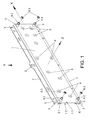
- the present device comprises a laminar body (1), which in turn comprises a front side (1.1) and a rear side (1.2).
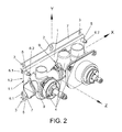
- the front side (1.1) is configured to be arranged facing the fittings which are fastened to the device through housings (9). Said fastening is carried out by partially inserting the fittings in the housings (9) or through conventional fastening means in said housings (9).
- the rear side (1.2) whereas is configured to be arranged facing the surface or wall (8) onto which the device which is the object of the present invention is fastened.
- the laminar body (1) comprises several lengths depending on the number of fittings to be housed. Should the number of fittings be higher than one, these are to be arranged with respect to the horizontal coordinate axis (X), as it is shown in Figures 2 and 4 . Therefore, the dimensions, and especially the horizontal extension, are variable, depending on the number and size of fittings to be housed.
- the device also comprises fastening orifices (2, 3) with the aim of fastening the device to the wall (8).
- the fastening orifices (2, 3) comprise a central orifice (2) and at least two lateral orifices (3), one at each side of the central orifice (2), with respect to the horizontal coordinate axis (X).
- the central orifice (2) is an elongated orifice such that it has a linear stretch in an upward direction according to the position for use of the present device. This linear stretch has smaller dimensions than the rest of the orifices used for its levelling. Said central orifice (2) is clearly seen in Figures 1 and 2 .
- the present device comprises two profiles (7), arranged externally to the laminar body (1) in an upper edge and in a lower edge of the device, forming a step-shaped configuration with respect to the laminar body (1) towards the rear side (1.2), thus being located in a parallel plane with respect to the laminar body (1).
- the profiles (7) are configured to act as contact areas with the walls (8). Therefore, by means of the U-shaped transverse section, a cavity or hollow is created, which may attain the goal of solving irregularities on the walls (8) where the present device is fastened, thus facilitating both its fastening and levelling.
- the fastening orifices (2, 3) are arranged in the profiles (7) and are configured to be crossed by elements such as nails and screws to fasten this device to the wall (8).
- the central orifice (2) is arranged in the middle point of the horizontal longitudinal extension of the profile (7) arranged on the upper edge of the device, and on each of side of said orifice (2) there is at least one of the lateral orifices (3) also in said profile (7) separated with respect to the central orifice (2) to provide a stable fastening.
- the device comprises one of the lateral orifices (3) in each of the corners of the device.
- no central orifice (2) is arranged, but two of the lateral orifices (3) separated from each other are included so as to provide the device with stable fastening.
- the device which is the object of the present invention also comprises levelling means (5, 6).
- the number and the location of the levelling means (5, 6) vary based on aspects such as the dimensions of the device, number and weight of the fittings to be housed, status of the wall (8), etc.
- the device comprises one of the levelling means (5, 6) in each of the corners of the laminar body (1).
- Each of the levelling means (5, 6) comprises an internally threaded body (5) and an externally threaded extension element (6) to be threadable through the threaded body (5) by a user manipulating the present device.
- the threaded body (5) is arranged making up a unitary element together with the laminar body (1), although in another preferred embodiment they are independent elements joined to the laminar body (1), for example, by welding, now stapling
- each of the extension elements (6) is arranged threaded through the related threaded body (5), also passing through the laminar body (1).
- the extension elements (6) comprise a head (6.2) at the end of each of the extension elements (6) arranged in the front side (1.1) with the aim of serving as handling point of said extension elements (6) to be then threaded to a greater or lesser extent.
- the heads (6.2) may be handled manually or by means of mechanical elements such as screwdrivers or the like.
- Each extension element (6) is immobilized by means of a locknut (6.3) coupled to said extension element (5).
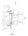
- each of the extension elements (6) arranged in the rear side (1.2) serve as support against the wall (8) onto which the present devices are fastened. Due to this goal of the ends of the extension elements (6), in a preferred embodiment, said extension elements (6) additionally comprise a support (6.1) at each of said ends, being the supports (6.1) clearly appreciated in Figures 2 and 3 .
- the supports (6.1) are aimed to increasing the contact surface between the extension elements (6) and the wall (8), apart from providing a support that does not damage or alter the contact surface between the extension elements (6) and the wall (8).
- the supports (6.1), in its most retracted position, are housed in the hollow or cavity generated by the step existing between the laminar body (1) and the profiles (7), not preventing the present device from being fastened or levelled should it not be required its extension or protuberance with respect to the laminar body (1), and the profiles (7), to level said device.
- extension elements (6) The main goal of these extension elements (6) is having an adjustable extension from their rear side (1.2), individually, to solve or compensate irregularities and/or inclination on the wall (8) area onto which the present device is fastened.
- An example is shown in Figure 3 wherein an inclination is compensated with respect to a vertical plane by means of a pair of extension elements (6) close to the profile (7) arranged on the upper edge. If the inclination is opposite to the one shown in Figure 3 , the device comprises the extension elements (6) closest to the lower edge of the device.
- the device may comprise some of the extension elements (6) close to the upper edge and other extension elements (6) close to the lower edge, maintaining the related ones in the retracted position, the supports close to the laminar body (1), and the related ones extended, that is with the supports (6.1) as far from the laminar body (1) as it is required.
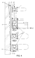
- FIG 4 An example similar to the above-mentioned situation is shown in Figure 4 , where three out of the four supports (6.1) comprised in the device, are appreciated, each of them being extended at different extents according to the wall (8) requirements resulting from the irregularities thereon.
- the first step is to place the device in such a way that a screw or nail arranged in the wall (8) is arranged through the central orifice (2).
- the device simply hangs from said screw or nail, its position not being fastened. It is thus horizontally levelled, that is, a horizontal longitudinal axis that goes through the device through its centre with respect to the horizontal coordinate axis (X) is levelled.
- a level may be employed to facilitate said horizontal levelling.
- blind bores need to be carried out in the wall, using the lateral orifices (3) of the profile (7) to mark them on said wall.
- nails or screws are inserted to pre-fasten the device onto the wall (8) by partially inserting it in said wall (8).
- these nails or screws are not completely inserted, only insofar as it is necessary to maintain the device in horizontal position.
- the nails or screws located through the lateral orifices (3) fasten in a definite manner the position of the device by being introduced to the greatest extent possible according to the levelling and positioning established by the extension elements (6), that is to say by the levelling means (5, 6).
- the nails or screws may be inserted to the greatest extent possible according to the levelling and positioning established by the extension elements (6) for its definitive fastening.
- Additional elements may be used such as the level to arrange the device with the inclination or angle desired at any time during the fastening and levelling of the present device.
Abstract
Description
- This invention refers to a device for fastening and levelling sanitary fittings onto walls with respect to the three coordinate axes.
- It is of utmost importance that upon fastening or installing sanitary fittings on walls they are arranged forming a desired angle with respect to each of the three coordinate axes (X, Y, Z). This is so because these sanitary fittings are joined or connected to additional fittings that provide continuity to the plumbing installation, etc.
- In this way, if the sanitary fittings are not fastened in the desired angle, the installation of subsequent fittings is thus undesirably restricted. The final result may not be successful when tile lines (tile joints), both vertical and horizontal, do not match.
- Usually, each wall onto which sanitary fittings are to be installed creates a different angle with respect to a vertical plane. In addition, walls usually comprise irregularities that make the fastening of said fittings with the desired arrangement even more complicated.
- Nowadays supports for the appropriate levelling of the sanitary fittings with respect to the three coordinate axes (X, Y, Z) according to a desired angle are known. However, a problem with these supports is that they comprise complex levelling systems which, depending on the space available, sometimes complicate even more the correct fastening of the sanitary fittings. Another problem of said supports is that they also entail an additional cost due to their complex manufacturing, assembly and installation.
- With the aim of attaining these goals and solving the different technical problems mentioned so far, apart from others described further on, the present invention describes a device for fastening and levelling sanitary fitting onto walls, comprising a laminar body, which in turn comprises a front side to be arranged facing the sanitary fittings fastened to the laminar body; and a rear side to be arranged facing the wall.
- An important feature of the present invention is that the device additionally comprises: two profiles, one in an upper edge and another one in a lower edge of the laminar body based on how the device is fastened to the wall, both profiles being arranged in a displaced plane relative to the laminar body towards the rear side; fastening orifices to fasten the device to the wall, which comprise a central orifice arranged in a middle point of the longitudinal extension of the profile of the upper edge and lateral orifices at least in the profile of the upper edge; and levelling means arranged in the laminar body, each of which being individually adjustable throughout its length with respect to the rear side and providing support against the wall.
- In this way, it is possible to fasten and level the device with respect to the three coordinate axes by means of the combined adjustment of the fastening orifices and levelling means, the fastening orifices and the levelling means being handled independently from each other.
- Another important feature of the present invention is that each of the levelling means comprises a threaded body and an externally threaded extension element to be threadable through the threaded body.
- Additionally, each of the extension elements may comprise a bed to provide support against the wall and a head for its handling. Each extension element is immobilized by means of a locknut.
- For a better understanding of the present description, the invention is complemented with a set of drawings in which, for illustration purposes and without limitation, the following has been represented:
-
Figure 1 shows a perspective view of the device for fastening and levelling sanitary fittings onto walls which is the object of the present invention, according to a preferred embodiment. -
Figure 2 shows a perspective view of the complete device for fastening and levelling sanitary fittings onto walls which is the object of the present invention, with sanitary fittings fastened thereto, according to another preferred embodiment. -
Figure 3 shows a lateral view of the device for fastening and levelling sanitary fittings onto walls which is the object of the present invention, with sanitary fittings fastened thereto, according to another preferred embodiment. -
Figure 4 shows a cross-sectional elevation view of the device for fastening and levelling sanitary fittings onto walls which is the object of the present invention, with sanitary fittings fastened thereto, according to another preferred embodiment. - Below is a list of the different components that have been represented in the drawings and which are comprised in the invention:
- X = Horizontal coordinate axis
- X = Vertical coordinate axis
- Z = Depth coordinate axis
- 1 = Laminar body
- 1.1 = Front side
- 1.2 = Rear side
- 2 = Central orifice for planning or marking
- 3 = Lateral orifice
- 4 = Sanitary fitting
- 5 = Threaded body
- 6 = Extension element
- 6.1 = Support
- 6.2 = Head
- 6.3 = Locknut
- 7 = Profile
- 8 = Wall
- 9 = Housings
- As previously mentioned, and as it appears in the figures, the present invention describes a device for fastening and levelling sanitary fittings onto walls (8), despite them being walls (8) with undesired inclination and/or superficial irregularities. The present device is simple and easy to use for obtaining a desired orientation with respect to a horizontal coordinate axis (X), a vertical coordinate axis (Y) and a depth coordinate axis (Z), that is to say with respect to each of the three coordinate axes (X, Y, Z).
- The present device comprises a laminar body (1), which in turn comprises a front side (1.1) and a rear side (1.2). The front side (1.1) is configured to be arranged facing the fittings which are fastened to the device through housings (9). Said fastening is carried out by partially inserting the fittings in the housings (9) or through conventional fastening means in said housings (9). The rear side (1.2) whereas is configured to be arranged facing the surface or wall (8) onto which the device which is the object of the present invention is fastened.
- Preferably, the laminar body (1) comprises several lengths depending on the number of fittings to be housed. Should the number of fittings be higher than one, these are to be arranged with respect to the horizontal coordinate axis (X), as it is shown in
Figures 2 and4 . Therefore, the dimensions, and especially the horizontal extension, are variable, depending on the number and size of fittings to be housed. - The device also comprises fastening orifices (2, 3) with the aim of fastening the device to the wall (8). In a preferred embodiment, the fastening orifices (2, 3) comprise a central orifice (2) and at least two lateral orifices (3), one at each side of the central orifice (2), with respect to the horizontal coordinate axis (X). Preferably, although not necessarily, the central orifice (2) is an elongated orifice such that it has a linear stretch in an upward direction according to the position for use of the present device. This linear stretch has smaller dimensions than the rest of the orifices used for its levelling. Said central orifice (2) is clearly seen in
Figures 1 and2 . - Additionally, the present device according to a preferred embodiment comprises two profiles (7), arranged externally to the laminar body (1) in an upper edge and in a lower edge of the device, forming a step-shaped configuration with respect to the laminar body (1) towards the rear side (1.2), thus being located in a parallel plane with respect to the laminar body (1). The profiles (7) are configured to act as contact areas with the walls (8). Therefore, by means of the U-shaped transverse section, a cavity or hollow is created, which may attain the goal of solving irregularities on the walls (8) where the present device is fastened, thus facilitating both its fastening and levelling.
- The fastening orifices (2, 3) are arranged in the profiles (7) and are configured to be crossed by elements such as nails and screws to fasten this device to the wall (8).
- In the preferred embodiment shown in
Figure 2 , which comprises a smaller horizontal longitudinal extension than the preferred embodiment shown inFigure 1 , the central orifice (2) is arranged in the middle point of the horizontal longitudinal extension of the profile (7) arranged on the upper edge of the device, and on each of side of said orifice (2) there is at least one of the lateral orifices (3) also in said profile (7) separated with respect to the central orifice (2) to provide a stable fastening. Both in the preferred embodiment shown inFigure 1 and in that shown inFigure 2 , the device comprises one of the lateral orifices (3) in each of the corners of the device. - In the profile (7) arranged on the lower edge, no central orifice (2) is arranged, but two of the lateral orifices (3) separated from each other are included so as to provide the device with stable fastening. The greater the longitudinal extension with respect to the horizontal coordinate axis (X), the greater the number of lateral orifices (3) are located in the device, the lateral orifices (3) being separated from each other so that stable fastening is provided.
- The device which is the object of the present invention also comprises levelling means (5, 6). The number and the location of the levelling means (5, 6) vary based on aspects such as the dimensions of the device, number and weight of the fittings to be housed, status of the wall (8), etc. In the preferred embodiments shown in
Figures 1 and2 , the device comprises one of the levelling means (5, 6) in each of the corners of the laminar body (1). - Each of the levelling means (5, 6) comprises an internally threaded body (5) and an externally threaded extension element (6) to be threadable through the threaded body (5) by a user manipulating the present device.
- The threaded body (5) is arranged making up a unitary element together with the laminar body (1), although in another preferred embodiment they are independent elements joined to the laminar body (1), for example, by welding, now stapling As it may be observed in the figures, each of the extension elements (6) is arranged threaded through the related threaded body (5), also passing through the laminar body (1).
- The extension elements (6) comprise a head (6.2) at the end of each of the extension elements (6) arranged in the front side (1.1) with the aim of serving as handling point of said extension elements (6) to be then threaded to a greater or lesser extent. The heads (6.2) may be handled manually or by means of mechanical elements such as screwdrivers or the like.
- Each extension element (6) is immobilized by means of a locknut (6.3) coupled to said extension element (5).
- The opposite ends, that is, the ends of each of the extension elements (6) arranged in the rear side (1.2) serve as support against the wall (8) onto which the present devices are fastened. Due to this goal of the ends of the extension elements (6), in a preferred embodiment, said extension elements (6) additionally comprise a support (6.1) at each of said ends, being the supports (6.1) clearly appreciated in
Figures 2 and3 . - Among other objects, the supports (6.1) are aimed to increasing the contact surface between the extension elements (6) and the wall (8), apart from providing a support that does not damage or alter the contact surface between the extension elements (6) and the wall (8). The supports (6.1), in its most retracted position, are housed in the hollow or cavity generated by the step existing between the laminar body (1) and the profiles (7), not preventing the present device from being fastened or levelled should it not be required its extension or protuberance with respect to the laminar body (1), and the profiles (7), to level said device.
- The main goal of these extension elements (6) is having an adjustable extension from their rear side (1.2), individually, to solve or compensate irregularities and/or inclination on the wall (8) area onto which the present device is fastened. An example is shown in
Figure 3 wherein an inclination is compensated with respect to a vertical plane by means of a pair of extension elements (6) close to the profile (7) arranged on the upper edge. If the inclination is opposite to the one shown inFigure 3 , the device comprises the extension elements (6) closest to the lower edge of the device. - In both cases, the device may comprise some of the extension elements (6) close to the upper edge and other extension elements (6) close to the lower edge, maintaining the related ones in the retracted position, the supports close to the laminar body (1), and the related ones extended, that is with the supports (6.1) as far from the laminar body (1) as it is required. An example similar to the above-mentioned situation is shown in
Figure 4 , where three out of the four supports (6.1) comprised in the device, are appreciated, each of them being extended at different extents according to the wall (8) requirements resulting from the irregularities thereon. - For the fastening and levelling of the present device, the first step is to place the device in such a way that a screw or nail arranged in the wall (8) is arranged through the central orifice (2). The device simply hangs from said screw or nail, its position not being fastened. It is thus horizontally levelled, that is, a horizontal longitudinal axis that goes through the device through its centre with respect to the horizontal coordinate axis (X) is levelled. A level may be employed to facilitate said horizontal levelling.
- It is worth noting that, before inserting the screws, blind bores need to be carried out in the wall, using the lateral orifices (3) of the profile (7) to mark them on said wall.
- Later, through at least some lateral orifices (3), nails or screws are inserted to pre-fasten the device onto the wall (8) by partially inserting it in said wall (8). Preferably, these nails or screws are not completely inserted, only insofar as it is necessary to maintain the device in horizontal position. Afterwards, with the individual adjustment of each of the levelling means (5, 6) by screwing or unscrewing the extension elements (6) through the threaded bodies (5), the position is finally defined with respect to the three coordinate axes (X, Y, Z).
- Once it is positioned as desired, the nails or screws located through the lateral orifices (3) fasten in a definite manner the position of the device by being introduced to the greatest extent possible according to the levelling and positioning established by the extension elements (6), that is to say by the levelling means (5, 6). When there are some of the lateral orifices (3) where no nails or screws have been introduced to pre-fasten the device to the wall (8), the nails or screws may be inserted to the greatest extent possible according to the levelling and positioning established by the extension elements (6) for its definitive fastening.
- Additional elements may be used such as the level to arrange the device with the inclination or angle desired at any time during the fastening and levelling of the present device.
- Once the nature of the invention has been described, it is thus stated, for the relevant purposes, that it is not limited to the exact details of this description, but on the contrary, whichever amendments are deemed appropriate may be introduced, insofar as the essential features thereon are not altered. In consequence, the scope of the invention is defined by the following claims.
Claims (3)
- Device for fastening and levelling sanitary fittings onto walls (8), comprising:- a laminar body (1), which in turn comprises:characterized in that the device additionally comprises:o a front side (1.1) to be arranged facing the sanitary fittings (4) fastened to the laminar body (1); ando a rear side (1.2) to be arranged facing the wall (8);- two profiles (7) integrated in the laminar body (1), one on an upper edge and another one on a lower edge of the laminar body (1) according to the position of the device being fastened to the wall (8), both profiles (7) being arranged in a displaced plane with respect to the laminar body (1) towards the rear side (1.2);- fastening orifices (2, 3) to fasten the device to the wall (8), comprising:o a central orifice (2) arranged in a middle point of the longitudinal extension of the profile (7) of the upper edge, ando lateral orifices (3) at least in the profile (7) of the upper and lower edge;- levelling means (5, 6) arranged in the laminar body (1), the extension of each being individually adjustable with respect to the rear side (1.2) and providing support against the wall (8);such that the device is to be fastened and levelled with respect to the three coordinate axes (X, Y, Z) by means of the combined adjustment of the fastening orifices (2, 3) and the levelling means (5, 6), the fastening orifices (2, 3) and the levelling means (5, 6) being handled independently from each other.
- Device according to claim 1, characterized in that each of the levelling means (5, 6) comprises a threaded body (5) and an extension element (6) externally threaded to be threadable through the threaded body (5); where the extension element (6) is immobilized by a locknut (6.3) coupled to said extension element (5).
- Device according to claim 2, characterized in that each of the extension elements (6) comprises a support (6.1) to provide support against the wall (8) and a head (6.2) for its handling.
Priority Applications (1)
| Application Number | Priority Date | Filing Date | Title |
|---|---|---|---|
| PL15192906T PL3040486T3 (en) | 2014-12-30 | 2015-11-04 | Device for fastening and levelling sanitary fittings onto walls |
Applications Claiming Priority (1)
| Application Number | Priority Date | Filing Date | Title |
|---|---|---|---|
| ES201431695U ES1135619Y (en) | 2014-12-30 | 2014-12-30 | Device for fixing and leveling sanitation accessories on walls |
Publications (2)
| Publication Number | Publication Date |
|---|---|
| EP3040486A1 true EP3040486A1 (en) | 2016-07-06 |
| EP3040486B1 EP3040486B1 (en) | 2019-03-13 |
Family
ID=52389153
Family Applications (1)
| Application Number | Title | Priority Date | Filing Date |
|---|---|---|---|
| EP15192906.4A Not-in-force EP3040486B1 (en) | 2014-12-30 | 2015-11-04 | Device for fastening and levelling sanitary fittings onto walls |
Country Status (3)
| Country | Link |
|---|---|
| EP (1) | EP3040486B1 (en) |
| ES (2) | ES1135619Y (en) |
| PL (1) | PL3040486T3 (en) |
Cited By (2)
| Publication number | Priority date | Publication date | Assignee | Title |
|---|---|---|---|---|
| DK201600414A1 (en) * | 2016-07-12 | 2018-01-22 | Ebbe Schødt Søndergaard | Adjustable Mounting Bracket |
| GR1009369B (en) * | 2017-05-11 | 2018-10-01 | Πανος Διονυσιου Τερζοπουλος | Base-blade furnished with integral spirit levels and destined for the fixation of water supply fixtures |
Families Citing this family (1)
| Publication number | Priority date | Publication date | Assignee | Title |
|---|---|---|---|---|
| ES2697061B2 (en) * | 2017-07-21 | 2020-03-20 | Tor Mans S L | POSITIONING DEVICE, SYSTEM AND PROCEDURE FOR HYDRAULIC INSTALLATIONS IN A PARAMENT |
Citations (3)
| Publication number | Priority date | Publication date | Assignee | Title |
|---|---|---|---|---|
| EP0609973A1 (en) * | 1993-02-01 | 1994-08-10 | MANNESMANN Aktiengesellschaft | Device for fixing of angled coverbrackets |
| DE102007055565B3 (en) * | 2007-11-20 | 2009-04-16 | Aloys F. Dornbracht Gmbh & Co. Kg | Device for concealed fixing of sanitary elements |
| DE102011082120A1 (en) * | 2011-09-05 | 2013-03-07 | Hansgrohe Se | Terminal block for connection of sanitary fitting to domestic installation, has connecting pipe that connects connection element with base, and adjusting element that angularly orients connection element relative to base |
-
2014
- 2014-12-30 ES ES201431695U patent/ES1135619Y/en not_active Expired - Fee Related
-
2015
- 2015-11-04 ES ES15192906T patent/ES2721265T3/en active Active
- 2015-11-04 EP EP15192906.4A patent/EP3040486B1/en not_active Not-in-force
- 2015-11-04 PL PL15192906T patent/PL3040486T3/en unknown
Patent Citations (3)
| Publication number | Priority date | Publication date | Assignee | Title |
|---|---|---|---|---|
| EP0609973A1 (en) * | 1993-02-01 | 1994-08-10 | MANNESMANN Aktiengesellschaft | Device for fixing of angled coverbrackets |
| DE102007055565B3 (en) * | 2007-11-20 | 2009-04-16 | Aloys F. Dornbracht Gmbh & Co. Kg | Device for concealed fixing of sanitary elements |
| DE102011082120A1 (en) * | 2011-09-05 | 2013-03-07 | Hansgrohe Se | Terminal block for connection of sanitary fitting to domestic installation, has connecting pipe that connects connection element with base, and adjusting element that angularly orients connection element relative to base |
Cited By (3)
| Publication number | Priority date | Publication date | Assignee | Title |
|---|---|---|---|---|
| DK201600414A1 (en) * | 2016-07-12 | 2018-01-22 | Ebbe Schødt Søndergaard | Adjustable Mounting Bracket |
| DK179351B1 (en) * | 2016-07-12 | 2018-05-14 | Soendergaard Ebbe Schoedt | Adjustable Mounting Bracket |
| GR1009369B (en) * | 2017-05-11 | 2018-10-01 | Πανος Διονυσιου Τερζοπουλος | Base-blade furnished with integral spirit levels and destined for the fixation of water supply fixtures |
Also Published As
| Publication number | Publication date |
|---|---|
| ES2721265T3 (en) | 2019-07-30 |
| ES1135619U (en) | 2015-01-28 |
| ES1135619Y (en) | 2015-04-20 |
| PL3040486T3 (en) | 2019-09-30 |
| EP3040486B1 (en) | 2019-03-13 |
Similar Documents
| Publication | Publication Date | Title |
|---|---|---|
| US8939416B2 (en) | Front adjustable wall panel mounting device | |
| US10012366B2 (en) | Pot light assembly | |
| EP3040486A1 (en) | Device for fastening and levelling sanitary fittings onto walls | |
| CN105793501A (en) | Mount for panel | |
| US20150060616A1 (en) | Adjustable television nook mount | |
| CN205065190U (en) | Anchoring system | |
| EP3020884A8 (en) | Curtain façade construction | |
| KR101631689B1 (en) | Complex anchor system | |
| IT201600070881A1 (en) | JUNCTION SYSTEM WITH LEVELER FOR FURNITURE PARTS AND FURNISHING ITEMS | |
| RU147534U1 (en) | FASTENING BRACKET | |
| US9617743B2 (en) | Primary and intermediate horizontal leveler | |
| US20190161982A1 (en) | Compensating element | |
| US20190218774A1 (en) | System for the partition of spaces | |
| US9845818B2 (en) | Coupling device and lamp apparatus having the same | |
| US20180100307A1 (en) | Adjustable lintel | |
| RU151327U1 (en) | BRACKET FOR INSTALLING FRAME STRUCTURES IN OPENINGS | |
| JP2012154084A (en) | Fitting frame adjuster and fitting frame adjustment structure | |
| JP6560008B2 (en) | Mounting structure of upper frame material in partition device and partition device using the same | |
| RU147935U1 (en) | FASTENING BRACKET | |
| JP2016508929A (en) | Connecting means | |
| KR101980958B1 (en) | Independently height-adjustable left and right vertical part of ladder | |
| JP6158894B2 (en) | Finishing method of concrete casting surface and top end setting device used therefor | |
| US20190128066A1 (en) | Ladder Safety Device | |
| EP4030017A4 (en) | Floor tile levelling device | |
| EP2942450A1 (en) | Method and fastener for fastening a rail |
Legal Events
| Date | Code | Title | Description |
|---|---|---|---|
| PUAI | Public reference made under article 153(3) epc to a published international application that has entered the european phase |
Free format text: ORIGINAL CODE: 0009012 |
|
| AK | Designated contracting states |
Kind code of ref document: A1 Designated state(s): AL AT BE BG CH CY CZ DE DK EE ES FI FR GB GR HR HU IE IS IT LI LT LU LV MC MK MT NL NO PL PT RO RS SE SI SK SM TR |
|
| AX | Request for extension of the european patent |
Extension state: BA ME |
|
| STAA | Information on the status of an ep patent application or granted ep patent |
Free format text: STATUS: REQUEST FOR EXAMINATION WAS MADE |
|
| 17P | Request for examination filed |
Effective date: 20161223 |
|
| RBV | Designated contracting states (corrected) |
Designated state(s): AL AT BE BG CH CY CZ DE DK EE ES FI FR GB GR HR HU IE IS IT LI LT LU LV MC MK MT NL NO PL PT RO RS SE SI SK SM TR |
|
| STAA | Information on the status of an ep patent application or granted ep patent |
Free format text: STATUS: EXAMINATION IS IN PROGRESS |
|
| 17Q | First examination report despatched |
Effective date: 20170628 |
|
| GRAP | Despatch of communication of intention to grant a patent |
Free format text: ORIGINAL CODE: EPIDOSNIGR1 |
|
| STAA | Information on the status of an ep patent application or granted ep patent |
Free format text: STATUS: GRANT OF PATENT IS INTENDED |
|
| INTG | Intention to grant announced |
Effective date: 20181205 |
|
| GRAS | Grant fee paid |
Free format text: ORIGINAL CODE: EPIDOSNIGR3 |
|
| GRAA | (expected) grant |
Free format text: ORIGINAL CODE: 0009210 |
|
| STAA | Information on the status of an ep patent application or granted ep patent |
Free format text: STATUS: THE PATENT HAS BEEN GRANTED |
|
| AK | Designated contracting states |
Kind code of ref document: B1 Designated state(s): AL AT BE BG CH CY CZ DE DK EE ES FI FR GB GR HR HU IE IS IT LI LT LU LV MC MK MT NL NO PL PT RO RS SE SI SK SM TR |
|
| REG | Reference to a national code |
Ref country code: GB Ref legal event code: FG4D |
|
| REG | Reference to a national code |
Ref country code: CH Ref legal event code: EP Ref country code: AT Ref legal event code: REF Ref document number: 1107842 Country of ref document: AT Kind code of ref document: T Effective date: 20190315 |
|
| REG | Reference to a national code |
Ref country code: IE Ref legal event code: FG4D |
|
| REG | Reference to a national code |
Ref country code: DE Ref legal event code: R096 Ref document number: 602015026225 Country of ref document: DE |
|
| REG | Reference to a national code |
Ref country code: NL Ref legal event code: MP Effective date: 20190313 |
|
| REG | Reference to a national code |
Ref country code: LT Ref legal event code: MG4D |
|
| REG | Reference to a national code |
Ref country code: ES Ref legal event code: FG2A Ref document number: 2721265 Country of ref document: ES Kind code of ref document: T3 Effective date: 20190730 |
|
| PG25 | Lapsed in a contracting state [announced via postgrant information from national office to epo] |
Ref country code: LT Free format text: LAPSE BECAUSE OF FAILURE TO SUBMIT A TRANSLATION OF THE DESCRIPTION OR TO PAY THE FEE WITHIN THE PRESCRIBED TIME-LIMIT Effective date: 20190313 Ref country code: FI Free format text: LAPSE BECAUSE OF FAILURE TO SUBMIT A TRANSLATION OF THE DESCRIPTION OR TO PAY THE FEE WITHIN THE PRESCRIBED TIME-LIMIT Effective date: 20190313 Ref country code: NO Free format text: LAPSE BECAUSE OF FAILURE TO SUBMIT A TRANSLATION OF THE DESCRIPTION OR TO PAY THE FEE WITHIN THE PRESCRIBED TIME-LIMIT Effective date: 20190613 Ref country code: SE Free format text: LAPSE BECAUSE OF FAILURE TO SUBMIT A TRANSLATION OF THE DESCRIPTION OR TO PAY THE FEE WITHIN THE PRESCRIBED TIME-LIMIT Effective date: 20190313 |
|
| PG25 | Lapsed in a contracting state [announced via postgrant information from national office to epo] |
Ref country code: LV Free format text: LAPSE BECAUSE OF FAILURE TO SUBMIT A TRANSLATION OF THE DESCRIPTION OR TO PAY THE FEE WITHIN THE PRESCRIBED TIME-LIMIT Effective date: 20190313 Ref country code: RS Free format text: LAPSE BECAUSE OF FAILURE TO SUBMIT A TRANSLATION OF THE DESCRIPTION OR TO PAY THE FEE WITHIN THE PRESCRIBED TIME-LIMIT Effective date: 20190313 Ref country code: GR Free format text: LAPSE BECAUSE OF FAILURE TO SUBMIT A TRANSLATION OF THE DESCRIPTION OR TO PAY THE FEE WITHIN THE PRESCRIBED TIME-LIMIT Effective date: 20190614 Ref country code: BG Free format text: LAPSE BECAUSE OF FAILURE TO SUBMIT A TRANSLATION OF THE DESCRIPTION OR TO PAY THE FEE WITHIN THE PRESCRIBED TIME-LIMIT Effective date: 20190613 Ref country code: HR Free format text: LAPSE BECAUSE OF FAILURE TO SUBMIT A TRANSLATION OF THE DESCRIPTION OR TO PAY THE FEE WITHIN THE PRESCRIBED TIME-LIMIT Effective date: 20190313 Ref country code: NL Free format text: LAPSE BECAUSE OF FAILURE TO SUBMIT A TRANSLATION OF THE DESCRIPTION OR TO PAY THE FEE WITHIN THE PRESCRIBED TIME-LIMIT Effective date: 20190313 |
|
| REG | Reference to a national code |
Ref country code: AT Ref legal event code: MK05 Ref document number: 1107842 Country of ref document: AT Kind code of ref document: T Effective date: 20190313 |
|
| PG25 | Lapsed in a contracting state [announced via postgrant information from national office to epo] |
Ref country code: PT Free format text: LAPSE BECAUSE OF FAILURE TO SUBMIT A TRANSLATION OF THE DESCRIPTION OR TO PAY THE FEE WITHIN THE PRESCRIBED TIME-LIMIT Effective date: 20190713 Ref country code: AL Free format text: LAPSE BECAUSE OF FAILURE TO SUBMIT A TRANSLATION OF THE DESCRIPTION OR TO PAY THE FEE WITHIN THE PRESCRIBED TIME-LIMIT Effective date: 20190313 Ref country code: SK Free format text: LAPSE BECAUSE OF FAILURE TO SUBMIT A TRANSLATION OF THE DESCRIPTION OR TO PAY THE FEE WITHIN THE PRESCRIBED TIME-LIMIT Effective date: 20190313 Ref country code: CZ Free format text: LAPSE BECAUSE OF FAILURE TO SUBMIT A TRANSLATION OF THE DESCRIPTION OR TO PAY THE FEE WITHIN THE PRESCRIBED TIME-LIMIT Effective date: 20190313 Ref country code: RO Free format text: LAPSE BECAUSE OF FAILURE TO SUBMIT A TRANSLATION OF THE DESCRIPTION OR TO PAY THE FEE WITHIN THE PRESCRIBED TIME-LIMIT Effective date: 20190313 Ref country code: EE Free format text: LAPSE BECAUSE OF FAILURE TO SUBMIT A TRANSLATION OF THE DESCRIPTION OR TO PAY THE FEE WITHIN THE PRESCRIBED TIME-LIMIT Effective date: 20190313 |
|
| PG25 | Lapsed in a contracting state [announced via postgrant information from national office to epo] |
Ref country code: SM Free format text: LAPSE BECAUSE OF FAILURE TO SUBMIT A TRANSLATION OF THE DESCRIPTION OR TO PAY THE FEE WITHIN THE PRESCRIBED TIME-LIMIT Effective date: 20190313 |
|
| REG | Reference to a national code |
Ref country code: DE Ref legal event code: R097 Ref document number: 602015026225 Country of ref document: DE |
|
| PG25 | Lapsed in a contracting state [announced via postgrant information from national office to epo] |
Ref country code: IS Free format text: LAPSE BECAUSE OF FAILURE TO SUBMIT A TRANSLATION OF THE DESCRIPTION OR TO PAY THE FEE WITHIN THE PRESCRIBED TIME-LIMIT Effective date: 20190713 Ref country code: AT Free format text: LAPSE BECAUSE OF FAILURE TO SUBMIT A TRANSLATION OF THE DESCRIPTION OR TO PAY THE FEE WITHIN THE PRESCRIBED TIME-LIMIT Effective date: 20190313 |
|
| PLBE | No opposition filed within time limit |
Free format text: ORIGINAL CODE: 0009261 |
|
| STAA | Information on the status of an ep patent application or granted ep patent |
Free format text: STATUS: NO OPPOSITION FILED WITHIN TIME LIMIT |
|
| PG25 | Lapsed in a contracting state [announced via postgrant information from national office to epo] |
Ref country code: DK Free format text: LAPSE BECAUSE OF FAILURE TO SUBMIT A TRANSLATION OF THE DESCRIPTION OR TO PAY THE FEE WITHIN THE PRESCRIBED TIME-LIMIT Effective date: 20190313 |
|
| 26N | No opposition filed |
Effective date: 20191216 |
|
| PG25 | Lapsed in a contracting state [announced via postgrant information from national office to epo] |
Ref country code: SI Free format text: LAPSE BECAUSE OF FAILURE TO SUBMIT A TRANSLATION OF THE DESCRIPTION OR TO PAY THE FEE WITHIN THE PRESCRIBED TIME-LIMIT Effective date: 20190313 |
|
| PG25 | Lapsed in a contracting state [announced via postgrant information from national office to epo] |
Ref country code: TR Free format text: LAPSE BECAUSE OF FAILURE TO SUBMIT A TRANSLATION OF THE DESCRIPTION OR TO PAY THE FEE WITHIN THE PRESCRIBED TIME-LIMIT Effective date: 20190313 |
|
| REG | Reference to a national code |
Ref country code: CH Ref legal event code: PL |
|
| PG25 | Lapsed in a contracting state [announced via postgrant information from national office to epo] |
Ref country code: LU Free format text: LAPSE BECAUSE OF NON-PAYMENT OF DUE FEES Effective date: 20191104 Ref country code: CH Free format text: LAPSE BECAUSE OF NON-PAYMENT OF DUE FEES Effective date: 20191130 Ref country code: LI Free format text: LAPSE BECAUSE OF NON-PAYMENT OF DUE FEES Effective date: 20191130 Ref country code: MC Free format text: LAPSE BECAUSE OF FAILURE TO SUBMIT A TRANSLATION OF THE DESCRIPTION OR TO PAY THE FEE WITHIN THE PRESCRIBED TIME-LIMIT Effective date: 20190313 |
|
| REG | Reference to a national code |
Ref country code: BE Ref legal event code: MM Effective date: 20191130 |
|
| GBPC | Gb: european patent ceased through non-payment of renewal fee |
Effective date: 20191104 |
|
| PG25 | Lapsed in a contracting state [announced via postgrant information from national office to epo] |
Ref country code: IE Free format text: LAPSE BECAUSE OF NON-PAYMENT OF DUE FEES Effective date: 20191104 Ref country code: GB Free format text: LAPSE BECAUSE OF NON-PAYMENT OF DUE FEES Effective date: 20191104 |
|
| PGFP | Annual fee paid to national office [announced via postgrant information from national office to epo] |
Ref country code: FR Payment date: 20200915 Year of fee payment: 6 |
|
| PG25 | Lapsed in a contracting state [announced via postgrant information from national office to epo] |
Ref country code: BE Free format text: LAPSE BECAUSE OF NON-PAYMENT OF DUE FEES Effective date: 20191130 |
|
| PGFP | Annual fee paid to national office [announced via postgrant information from national office to epo] |
Ref country code: ES Payment date: 20201201 Year of fee payment: 6 Ref country code: IT Payment date: 20201111 Year of fee payment: 6 Ref country code: DE Payment date: 20201126 Year of fee payment: 6 |
|
| PGFP | Annual fee paid to national office [announced via postgrant information from national office to epo] |
Ref country code: PL Payment date: 20201009 Year of fee payment: 6 |
|
| PG25 | Lapsed in a contracting state [announced via postgrant information from national office to epo] |
Ref country code: CY Free format text: LAPSE BECAUSE OF FAILURE TO SUBMIT A TRANSLATION OF THE DESCRIPTION OR TO PAY THE FEE WITHIN THE PRESCRIBED TIME-LIMIT Effective date: 20190313 |
|
| PG25 | Lapsed in a contracting state [announced via postgrant information from national office to epo] |
Ref country code: MT Free format text: LAPSE BECAUSE OF FAILURE TO SUBMIT A TRANSLATION OF THE DESCRIPTION OR TO PAY THE FEE WITHIN THE PRESCRIBED TIME-LIMIT Effective date: 20190313 Ref country code: HU Free format text: LAPSE BECAUSE OF FAILURE TO SUBMIT A TRANSLATION OF THE DESCRIPTION OR TO PAY THE FEE WITHIN THE PRESCRIBED TIME-LIMIT; INVALID AB INITIO Effective date: 20151104 |
|
| REG | Reference to a national code |
Ref country code: DE Ref legal event code: R119 Ref document number: 602015026225 Country of ref document: DE |
|
| PG25 | Lapsed in a contracting state [announced via postgrant information from national office to epo] |
Ref country code: MK Free format text: LAPSE BECAUSE OF FAILURE TO SUBMIT A TRANSLATION OF THE DESCRIPTION OR TO PAY THE FEE WITHIN THE PRESCRIBED TIME-LIMIT Effective date: 20190313 |
|
| PG25 | Lapsed in a contracting state [announced via postgrant information from national office to epo] |
Ref country code: DE Free format text: LAPSE BECAUSE OF NON-PAYMENT OF DUE FEES Effective date: 20220601 |
|
| PG25 | Lapsed in a contracting state [announced via postgrant information from national office to epo] |
Ref country code: FR Free format text: LAPSE BECAUSE OF NON-PAYMENT OF DUE FEES Effective date: 20211130 |
|
| PG25 | Lapsed in a contracting state [announced via postgrant information from national office to epo] |
Ref country code: IT Free format text: LAPSE BECAUSE OF NON-PAYMENT OF DUE FEES Effective date: 20211104 |
|
| REG | Reference to a national code |
Ref country code: ES Ref legal event code: FD2A Effective date: 20230214 |
|
| PG25 | Lapsed in a contracting state [announced via postgrant information from national office to epo] |
Ref country code: ES Free format text: LAPSE BECAUSE OF NON-PAYMENT OF DUE FEES Effective date: 20211105 |
|
| PG25 | Lapsed in a contracting state [announced via postgrant information from national office to epo] |
Ref country code: PL Free format text: LAPSE BECAUSE OF NON-PAYMENT OF DUE FEES Effective date: 20211104 |