EP3039287B1 - Verfahren zur bestimmung einer physikalischen grösse in einer verdrängerpumpe - Google Patents
Verfahren zur bestimmung einer physikalischen grösse in einer verdrängerpumpe Download PDFInfo
- Publication number
- EP3039287B1 EP3039287B1 EP14755358.0A EP14755358A EP3039287B1 EP 3039287 B1 EP3039287 B1 EP 3039287B1 EP 14755358 A EP14755358 A EP 14755358A EP 3039287 B1 EP3039287 B1 EP 3039287B1
- Authority
- EP
- European Patent Office
- Prior art keywords
- pressure
- displacer element
- set forth
- determined
- valve
- Prior art date
- Legal status (The legal status is an assumption and is not a legal conclusion. Google has not performed a legal analysis and makes no representation as to the accuracy of the status listed.)
- Active
Links
- 238000000034 method Methods 0.000 title claims description 49
- 238000006073 displacement reaction Methods 0.000 title claims description 22
- 239000012530 fluid Substances 0.000 claims description 56
- 230000033001 locomotion Effects 0.000 claims description 31
- 230000006870 function Effects 0.000 claims description 15
- 238000005457 optimization Methods 0.000 claims description 8
- 238000005259 measurement Methods 0.000 claims description 6
- 238000004364 calculation method Methods 0.000 claims description 5
- 238000013016 damping Methods 0.000 claims description 3
- 230000004044 response Effects 0.000 claims description 3
- 238000010586 diagram Methods 0.000 description 15
- 239000012528 membrane Substances 0.000 description 10
- 230000008859 change Effects 0.000 description 6
- 238000012937 correction Methods 0.000 description 5
- 230000008569 process Effects 0.000 description 5
- 238000005086 pumping Methods 0.000 description 4
- 230000002123 temporal effect Effects 0.000 description 4
- PEDCQBHIVMGVHV-UHFFFAOYSA-N Glycerine Chemical compound OCC(O)CO PEDCQBHIVMGVHV-UHFFFAOYSA-N 0.000 description 3
- 230000001133 acceleration Effects 0.000 description 3
- 230000004913 activation Effects 0.000 description 3
- 230000006835 compression Effects 0.000 description 3
- 238000007906 compression Methods 0.000 description 3
- 230000001105 regulatory effect Effects 0.000 description 3
- 238000012897 Levenberg–Marquardt algorithm Methods 0.000 description 2
- 230000009471 action Effects 0.000 description 2
- 238000013459 approach Methods 0.000 description 2
- 238000004140 cleaning Methods 0.000 description 2
- 238000011217 control strategy Methods 0.000 description 2
- 230000009849 deactivation Effects 0.000 description 2
- 238000001514 detection method Methods 0.000 description 2
- 238000003745 diagnosis Methods 0.000 description 2
- 230000004907 flux Effects 0.000 description 2
- 239000002655 kraft paper Substances 0.000 description 2
- 230000036962 time dependent Effects 0.000 description 2
- 238000012935 Averaging Methods 0.000 description 1
- 230000003466 anti-cipated effect Effects 0.000 description 1
- 230000004888 barrier function Effects 0.000 description 1
- 230000008901 benefit Effects 0.000 description 1
- 238000005352 clarification Methods 0.000 description 1
- 230000003247 decreasing effect Effects 0.000 description 1
- 230000001419 dependent effect Effects 0.000 description 1
- 238000013461 design Methods 0.000 description 1
- 238000011161 development Methods 0.000 description 1
- 238000012774 diagnostic algorithm Methods 0.000 description 1
- 238000002405 diagnostic procedure Methods 0.000 description 1
- 238000011156 evaluation Methods 0.000 description 1
- 230000006872 improvement Effects 0.000 description 1
- 230000000977 initiatory effect Effects 0.000 description 1
- 230000006855 networking Effects 0.000 description 1
- 230000000737 periodic effect Effects 0.000 description 1
- 230000036316 preload Effects 0.000 description 1
- 238000004540 process dynamic Methods 0.000 description 1
- 238000012545 processing Methods 0.000 description 1
- 230000000007 visual effect Effects 0.000 description 1
Images

Classifications
-
- F—MECHANICAL ENGINEERING; LIGHTING; HEATING; WEAPONS; BLASTING
- F04—POSITIVE - DISPLACEMENT MACHINES FOR LIQUIDS; PUMPS FOR LIQUIDS OR ELASTIC FLUIDS
- F04B—POSITIVE-DISPLACEMENT MACHINES FOR LIQUIDS; PUMPS
- F04B17/00—Pumps characterised by combination with, or adaptation to, specific driving engines or motors
- F04B17/03—Pumps characterised by combination with, or adaptation to, specific driving engines or motors driven by electric motors
- F04B17/04—Pumps characterised by combination with, or adaptation to, specific driving engines or motors driven by electric motors using solenoids
- F04B17/042—Pumps characterised by combination with, or adaptation to, specific driving engines or motors driven by electric motors using solenoids the solenoid motor being separated from the fluid flow
-
- F—MECHANICAL ENGINEERING; LIGHTING; HEATING; WEAPONS; BLASTING
- F04—POSITIVE - DISPLACEMENT MACHINES FOR LIQUIDS; PUMPS FOR LIQUIDS OR ELASTIC FLUIDS
- F04B—POSITIVE-DISPLACEMENT MACHINES FOR LIQUIDS; PUMPS
- F04B43/00—Machines, pumps, or pumping installations having flexible working members
- F04B43/02—Machines, pumps, or pumping installations having flexible working members having plate-like flexible members, e.g. diaphragms
- F04B43/04—Pumps having electric drive
-
- F—MECHANICAL ENGINEERING; LIGHTING; HEATING; WEAPONS; BLASTING
- F04—POSITIVE - DISPLACEMENT MACHINES FOR LIQUIDS; PUMPS FOR LIQUIDS OR ELASTIC FLUIDS
- F04B—POSITIVE-DISPLACEMENT MACHINES FOR LIQUIDS; PUMPS
- F04B49/00—Control, e.g. of pump delivery, or pump pressure of, or safety measures for, machines, pumps, or pumping installations, not otherwise provided for, or of interest apart from, groups F04B1/00 - F04B47/00
- F04B49/02—Stopping, starting, unloading or idling control
- F04B49/022—Stopping, starting, unloading or idling control by means of pressure
-
- F—MECHANICAL ENGINEERING; LIGHTING; HEATING; WEAPONS; BLASTING
- F04—POSITIVE - DISPLACEMENT MACHINES FOR LIQUIDS; PUMPS FOR LIQUIDS OR ELASTIC FLUIDS
- F04B—POSITIVE-DISPLACEMENT MACHINES FOR LIQUIDS; PUMPS
- F04B49/00—Control, e.g. of pump delivery, or pump pressure of, or safety measures for, machines, pumps, or pumping installations, not otherwise provided for, or of interest apart from, groups F04B1/00 - F04B47/00
- F04B49/06—Control using electricity
- F04B49/065—Control using electricity and making use of computers
-
- F—MECHANICAL ENGINEERING; LIGHTING; HEATING; WEAPONS; BLASTING
- F04—POSITIVE - DISPLACEMENT MACHINES FOR LIQUIDS; PUMPS FOR LIQUIDS OR ELASTIC FLUIDS
- F04B—POSITIVE-DISPLACEMENT MACHINES FOR LIQUIDS; PUMPS
- F04B49/00—Control, e.g. of pump delivery, or pump pressure of, or safety measures for, machines, pumps, or pumping installations, not otherwise provided for, or of interest apart from, groups F04B1/00 - F04B47/00
- F04B49/20—Control, e.g. of pump delivery, or pump pressure of, or safety measures for, machines, pumps, or pumping installations, not otherwise provided for, or of interest apart from, groups F04B1/00 - F04B47/00 by changing the driving speed
-
- F—MECHANICAL ENGINEERING; LIGHTING; HEATING; WEAPONS; BLASTING
- F04—POSITIVE - DISPLACEMENT MACHINES FOR LIQUIDS; PUMPS FOR LIQUIDS OR ELASTIC FLUIDS
- F04B—POSITIVE-DISPLACEMENT MACHINES FOR LIQUIDS; PUMPS
- F04B51/00—Testing machines, pumps, or pumping installations
-
- F—MECHANICAL ENGINEERING; LIGHTING; HEATING; WEAPONS; BLASTING
- F04—POSITIVE - DISPLACEMENT MACHINES FOR LIQUIDS; PUMPS FOR LIQUIDS OR ELASTIC FLUIDS
- F04B—POSITIVE-DISPLACEMENT MACHINES FOR LIQUIDS; PUMPS
- F04B53/00—Component parts, details or accessories not provided for in, or of interest apart from, groups F04B1/00 - F04B23/00 or F04B39/00 - F04B47/00
- F04B53/10—Valves; Arrangement of valves
-
- F—MECHANICAL ENGINEERING; LIGHTING; HEATING; WEAPONS; BLASTING
- F15—FLUID-PRESSURE ACTUATORS; HYDRAULICS OR PNEUMATICS IN GENERAL
- F15B—SYSTEMS ACTING BY MEANS OF FLUIDS IN GENERAL; FLUID-PRESSURE ACTUATORS, e.g. SERVOMOTORS; DETAILS OF FLUID-PRESSURE SYSTEMS, NOT OTHERWISE PROVIDED FOR
- F15B19/00—Testing; Calibrating; Fault detection or monitoring; Simulation or modelling of fluid-pressure systems or apparatus not otherwise provided for
- F15B19/007—Simulation or modelling
-
- G—PHYSICS
- G05—CONTROLLING; REGULATING
- G05B—CONTROL OR REGULATING SYSTEMS IN GENERAL; FUNCTIONAL ELEMENTS OF SUCH SYSTEMS; MONITORING OR TESTING ARRANGEMENTS FOR SUCH SYSTEMS OR ELEMENTS
- G05B13/00—Adaptive control systems, i.e. systems automatically adjusting themselves to have a performance which is optimum according to some preassigned criterion
- G05B13/02—Adaptive control systems, i.e. systems automatically adjusting themselves to have a performance which is optimum according to some preassigned criterion electric
- G05B13/04—Adaptive control systems, i.e. systems automatically adjusting themselves to have a performance which is optimum according to some preassigned criterion electric involving the use of models or simulators
-
- F—MECHANICAL ENGINEERING; LIGHTING; HEATING; WEAPONS; BLASTING
- F04—POSITIVE - DISPLACEMENT MACHINES FOR LIQUIDS; PUMPS FOR LIQUIDS OR ELASTIC FLUIDS
- F04B—POSITIVE-DISPLACEMENT MACHINES FOR LIQUIDS; PUMPS
- F04B2203/00—Motor parameters
- F04B2203/02—Motor parameters of rotating electric motors
- F04B2203/0201—Current
-
- F—MECHANICAL ENGINEERING; LIGHTING; HEATING; WEAPONS; BLASTING
- F04—POSITIVE - DISPLACEMENT MACHINES FOR LIQUIDS; PUMPS FOR LIQUIDS OR ELASTIC FLUIDS
- F04B—POSITIVE-DISPLACEMENT MACHINES FOR LIQUIDS; PUMPS
- F04B2203/00—Motor parameters
- F04B2203/04—Motor parameters of linear electric motors
- F04B2203/0401—Current
-
- F—MECHANICAL ENGINEERING; LIGHTING; HEATING; WEAPONS; BLASTING
- F04—POSITIVE - DISPLACEMENT MACHINES FOR LIQUIDS; PUMPS FOR LIQUIDS OR ELASTIC FLUIDS
- F04B—POSITIVE-DISPLACEMENT MACHINES FOR LIQUIDS; PUMPS
- F04B2203/00—Motor parameters
- F04B2203/04—Motor parameters of linear electric motors
- F04B2203/0402—Voltage
-
- F—MECHANICAL ENGINEERING; LIGHTING; HEATING; WEAPONS; BLASTING
- F05—INDEXING SCHEMES RELATING TO ENGINES OR PUMPS IN VARIOUS SUBCLASSES OF CLASSES F01-F04
- F05B—INDEXING SCHEME RELATING TO WIND, SPRING, WEIGHT, INERTIA OR LIKE MOTORS, TO MACHINES OR ENGINES FOR LIQUIDS COVERED BY SUBCLASSES F03B, F03D AND F03G
- F05B2210/00—Working fluid
- F05B2210/10—Kind or type
- F05B2210/11—Kind or type liquid, i.e. incompressible
-
- F—MECHANICAL ENGINEERING; LIGHTING; HEATING; WEAPONS; BLASTING
- F05—INDEXING SCHEMES RELATING TO ENGINES OR PUMPS IN VARIOUS SUBCLASSES OF CLASSES F01-F04
- F05B—INDEXING SCHEME RELATING TO WIND, SPRING, WEIGHT, INERTIA OR LIKE MOTORS, TO MACHINES OR ENGINES FOR LIQUIDS COVERED BY SUBCLASSES F03B, F03D AND F03G
- F05B2260/00—Function
- F05B2260/60—Fluid transfer
-
- Y—GENERAL TAGGING OF NEW TECHNOLOGICAL DEVELOPMENTS; GENERAL TAGGING OF CROSS-SECTIONAL TECHNOLOGIES SPANNING OVER SEVERAL SECTIONS OF THE IPC; TECHNICAL SUBJECTS COVERED BY FORMER USPC CROSS-REFERENCE ART COLLECTIONS [XRACs] AND DIGESTS
- Y10—TECHNICAL SUBJECTS COVERED BY FORMER USPC
- Y10S—TECHNICAL SUBJECTS COVERED BY FORMER USPC CROSS-REFERENCE ART COLLECTIONS [XRACs] AND DIGESTS
- Y10S417/00—Pumps
Definitions
- the present invention relates to a method for determining a physical quantity in a positive displacement pump.
- Positive displacement pumps generally have a movable displacement element which delimits the metering space, which in turn is connected via valves to a suction line and to a pressure line. This has the consequence that by an oscillating movement of the displacement element alternately conveying fluid can be sucked via the suction line into the dosing and pressed through the pressure line from the dosing.
- a drive for the oscillating movement of the displacer is provided.
- the displacer element is a membrane which can be moved back and forth between two extreme positions, wherein in the first extreme position the volume of the metering chamber is minimal, while in the second extreme position the volume of the metering chamber is maximal , Therefore, if the membrane is moved from its first position into the second, the pressure in the dosing chamber will drop, so that the conveying fluid is sucked into the dosing space via the suction line. In the return movement, i.
- the membrane In electromagnetically driven diaphragm pumps, the membrane is connected to a pressure piece, which is usually spring biased at least partially mounted within an electromagnet. As long as the electromagnet is not traversed by a current, so that no magnetic flux is built up in its interior, the resilient bias ensures that the pressure piece and thus the membrane in a predetermined position, for example, the second position, ie the position in the the dosing chamber has the largest volume remains.
- such electromagnetically driven diaphragm pumps are used when the volume of fluid to be metered is significantly greater than the Dosierraumvolumen, so that the metering rate is determined essentially by the frequency or the timing of the current flow through the electromagnet. If, for example, the dosing speed is to be doubled, then the electromagnet will flow through a current twice as often in the same time, which in turn results in twice the frequency of the movement cycle of the diaphragm.
- Such a magnetic metering pump is for example in the EP 1 757 809 described.
- magnetic metering pumps By regulating the movement of the pressure piece, magnetic metering pumps can also be used to promote significantly smaller quantities of fluid, since the lifting movement no longer takes place abruptly but regulated.
- valve opening and valve closing times of the metering pump play an essential role, since they determine the beginning and end of the actual metering process.
- gas bubbles in the hydraulic system and / or cavitations in the pump head of the dosing unit can reduce the actual dosing amount, which can significantly reduce the dosing accuracy, especially at very low dosing quantities.
- the metering chamber must be cleaned very thoroughly on a regular basis.
- the object is achieved by a method according to claim 1.
- An equation of motion is understood to mean a mathematical equation which describes the spatial and temporal movement of the displacer element under the influence of external influences.
- the present invention will initially be described below using the example of determining the fluid pressure. However, the invention is not limited to the determination of the fluid pressure. Further examples will be explained below.
- the measurement of the position of the displacer can be done without contact, for example, and is usually done anyway in the described metering pumps, so that the Information about the current position of the displacer is available.
- the equation of motion of the displacer takes into account all forces acting on the displacer. This is in addition to the force applied to the displacer by the drive force and the applied by the fluid pressure in the metering chamber on the membrane and thus on the displacer counterforce.
- the positive displacement pump is an electromagnetically driven metering pump, preferably an electromagnetically driven diaphragm pump.
- the force can be determined on the displacer by the drive and from the movement of the displacer then the pressure in the dosing head can be determined.
- a warning signal may be issued and the warning signal may be sent to an automatic cut-off device which shuts down the metering pump in response to the receipt of the warning signal. Should therefore for some reason a valve does not open or the pressure on the pressure line rise sharply, this can be determined by the inventive method without using a pressure sensor and the pump can be shut off for safety's sake.
- the displacement element with the associated drive additionally assumes the function of the pressure sensor.
- a target fluid pressure curve, a desired position curve of the displacer element and / or the desired current profile are stored by the electromagnetic drive for a movement cycle of the displacer element.
- the actual fluid pressure with the desired fluid pressure, the actual position of the displacer with the desired position of the displacer and / or the actual current can be compared by the electromagnetic drive with a desired current through the electromagnetic drive and, if the differences between the actual value and the target value fulfill a predetermined criterion, a warning signal is output.
- This method step is based on the idea that certain events, such as gas bubbles in the hydraulic system or cavitation in the pump head cause a recognizable change in the expected fluid pressure and therefore conclusions about the above events can be drawn from the determination of the fluid pressure.
- the warning signal can activate, for example, a visual display or an acoustic display. Alternatively or in combination, however, the warning signal can also be provided directly to a control unit, which takes appropriate action in response to the receipt of the warning signal.
- the difference between the actual and desired values is determined for one or more of the measured or determined variables, and if one of the differences exceeds a predetermined value, a warning signal is output.
- a weighted sum of the relative deviations from the target value may be determined and the criterion selected such that a warning signal is output when the weighted sum exceeds a predetermined value.
- the different error events can be assigned different weighting coefficients. Ideally, when a miss event occurs, exactly one criterion is met so that the fault event can be diagnosed.
- the temporal gradient of a measured or determined variable is determined and, if this exceeds a predetermined limit value, the valve opening or the valve closure is diagnosed.
- the mass m of the displacement element, the spring constant k of the spring biasing the displacement element, the damping d and / or the electrical resistance R Cu of the electromagnetic drive are determined as the physical variable.
- all of the variables mentioned are determined. This can be done for example by a minimization calculation.
- All of the above-mentioned variables represent constants which can be determined experimentally and generally do not change during pumping operation. Nevertheless, it can lead to fatigue of the different elements that change the value of the constant.
- the measured pressure-path curve can be compared with an expected pressure-path curve.
- the integrated over a cycle difference from both gradients can be minimized by varying the constant sizes. If one puts thereby for example If the spring constant has changed, a faulty spring can be diagnosed.
- the method according to the invention can be further developed in order to improve the control of the pressure piece movement, without a prior tabulation of control parameters being necessary. Thereby, the achievable with the positive displacement metering can be improved.
- a model-based control in particular a non-linear model-based control, is used to drive the displacement element.
- Characteristic of such a model-based control is therefore the constant calculation of the necessary control variable on the basis of measured variables using the system variables given by the model.
- displacement-pump-specific forces acting on the pressure piece are modeled in the differential equation.
- the force exerted by a spring on the pressure element, or its spring constant k, and / or the magnetic force exerted on the pressure element by the magnetic drive can be modeled.
- the force exerted by the conveying fluid on the pressure piece force can then be treated as a disturbance.
- the influence of the available manipulated variables on the controlled variable can be simulated in the same model. With the aid of known optimization methods, the currently best control strategy can then be selected adaptively. Alternatively, it is also possible to determine a control strategy once on the basis of the model and then to apply this as a function of the acquired measured variables.
- a nonlinear state space model is selected as the state space model and the nonlinear control takes place either via control Lyapunov functions, via flatness-based control methods with flatness-based feedforward control, via integrator backstepping methods, via sliding-mode methods or via predictive control.
- Nonlinear control over control Lyapunov functions is preferred.
- Control Lyapunov functions are a generalized description of Lyapunov functions. Appropriately chosen control Lyapunov functions lead to a stable behavior within the model.
- the model underlying the model-based control is used to formulate an optimization problem in which, as a constraint of the optimization, the electrical voltage at the electric motor and thus the energy supplied to the metering pump is as small as possible, but at the same time as fast and as little as possible overshooting approach of the actual profile to the target profile is achieved.
- the measured signals are low-pass filtered prior to processing in the underlying model to reduce the influence of noise.
- a self-learning system is realized here.
- the model-based control according to the invention has already led to a significant improvement in the control behavior, it can nevertheless lead to deviations between the desired profile and the actual profile. This is unavoidable especially in the case of energy-minimizing selection of the control intervention.
- the deviation is detected during one cycle and the detected deviation at the next cycle is at least partially subtracted from the desired setpoint position profile.
- a subsequent pressure-suction cycle is intentionally given a "wrong" setpoint profile, and the "wrong" setpoint profile is calculated from the experience gained in the previous cycle. If, in the following suction-pressure cycle, exactly the same deviation between the actual and desired profile occurs as in the previous cycle, then using the "wrong" setpoint profile results in the actual desired setpoint profile is reached.
- the difference between the actual and desired profile is determined at regular intervals, preferably at each cycle, and taken into account accordingly in the subsequent cycle.
- any function dependent on the detected difference may be used to correct the next desired position profile.
- a physical model with hydraulic parameters is also set up for the hydraulic system and that at least one hydraulic parameter is calculated with the aid of an optimization calculation.
- Hydraulic parameters are understood to mean any parameter of the hydraulic system, apart from the position of the displacer, which influences the flow of the fluid through the metering chamber.
- Hydraulic parameters are therefore e.g. the density of the delivery fluid in the dosing and the viscosity of the fluid in the dosing. Further hydraulic parameters are, for example, hose or pipe lengths and diameters of hoses and pipes which are at least temporarily connected to the metering space.
- hydraulic parameters can be determined without an additional sensor must be provided.
- valve to the suction line is open and the valve to the pressure line is closed.
- a flexible hose is mounted on the valve to the suction line, which ends in a reservoir under ambient pressure.
- This condition is during the so-called suction stroke, i. while the displacer moves from the second position to the first position.
- This hydraulic system could, for example, be described by means of the nonlinear Navier-Stokes equation taking into account laminar and turbulent flows.
- the diameter of the hose connecting the suction valve to the reservoir, the length of the hose and the difference in height, which must overcome the fluid in the hose, are to be considered as hydraulic parameters.
- the determination method according to the invention could be carried out solely by a repeated analysis of the suction stroke behavior.
- the physical model of the hydraulic system can be considered in the case that the valve is closed to the suction line and the valve is open to the pressure line.
- the pipe system connected to the pressure valve which connects the pressure line to the metering chamber is not known, only a generalized assumption can be made here , The established physical model can therefore be set up without knowledge of the connected to the pressure valve piping system, not in the accuracy, as is possible for the hydraulic system during the suction stroke in the rule.
- the set-up physical model with the hydraulic parameters determined in this way can be used, in turn, to determine the pressure in the dosing space.
- This knowledge can in turn be used to improve the motion control of the pressure piece by the force exerted by the fluid on the pressure piece force is modeled by the thus determined hydraulic parameters.
- Such a magnetic metering pump has a movable pressure piece with a push rod fixedly connected thereto.
- the pressure piece is axially movably mounted in a longitudinally fixed axis in the pump housing in the magnetic housing, so that the pressure piece with push rod in the electrical control of the solenoid is pulled in the magnetic sheath against the action of a compression spring in a bore of the magnetic shell and the pressure piece returns to the initial position after deactivation of the magnet by the compression spring.
- the force on the pressure piece can be determined by the fluid pressure in the delivery space. Since the surface of the pressure piece, which is acted upon by the fluid pressure is known, can be calculated from the force of the fluid pressure.
- the described design of a non-linear system description of the electromagnetic metering pump system makes it possible to use model-based diagnostic methods. For this, the state variables of the system models are evaluated and the pressure in the pump head of the electromagnetic dosing pump is determined. The necessary current and position sensors are already installed in the pump system for control purposes, so that the information is already available without the structure of the metering pump must be supplemented. Based on the temporal change of the state variables and the pressure in the dosing head of the pump, the diagnostic algorithms can then be executed.
- the model-based diagnosis of process-side overpressure and the automated pump shutdown can be realized.
- the detection of the valve opening and valve closing times can be done, for example, by determining and evaluating temporal gradients of coupled state variables of the system model.
- An overshoot or undershoot of the state gradients can be detected by means of predetermined barriers, which leads to the detection of the valve opening and valve closing times.
- the pressure in dependence on the position of the pressure piece can be determined and the valve opening and valve closing times are derived from an evaluation.
- a corresponding pressure-path diagram is in FIG. 1 shown on the left. In FIG. 1 on the right is the associated path-time diagram.
- FIG. 1 on the left the associated pressure-distance diagram is shown. It is traversed in a clockwise direction, starting at the point of origin, where the pressure piece is in position 1. During the pressure phase, the pressure in the dosing chamber will initially rise sharply until the pressure is able to open the valve to the pressure line. Once the pressure valve is opened, the pressure in the metering chamber remains substantially constant. The opening point is marked with the number 2. From this point in time also in FIG. 1 is entered on the right, it comes to a dosage. With each further movement of the pressure piece dosing fluid is pumped into the pressure line.
- time 3 As soon as the pressure piece has reached the maximum position (time 3), the movement of the pressure piece turns over, the pressure valve closes immediately and the pressure in the dosing chamber drops again. Once a minimum pressure is reached (time 4) opens the suction valve, which connects the dosing with the suction line, and dosing fluid is sucked into the dosing until the starting position is reached.
- the valve closing times can be determined from the path-time diagram, since they are on the maximum travel of the pressure piece.
- gas bubbles in the hydraulic system By comparing the desired and actual trajectories of the individual state variables of the system models, gas bubbles in the hydraulic system, cavitation in the pump head of the metering unit and / or valve opening and valve closing times of the metering units can be diagnosed. In particular, if a predetermined error limit is exceeded between the desired and actual trajectories, this can trigger a warning signal and corresponding measures.
- FIG. 2 An example is in FIG. 2 shown. Again, the pressure-distance diagram is shown on the left and the path-time diagram on the right. The right figure is identical to the corresponding diagram of FIG. 1 , If there are gas bubbles in the hydraulic system that are compressible cause that the pressure valve opens only at the time 2 'and the suction valve opens only at the time 4'. A clear shift of the valve opening times can thus be used to diagnose the condition "air in the metering chamber". In the case of cavitation, only the valve opening timing 4 'but not the valve opening timing 2 shifts so that such a behavior for diagnosing the "cavitation" state can be used.
- the presented model-based methodology allows a much more comprehensive and higher-quality diagnosis by analyzing the individual coupled system state variables than has hitherto been realized.
- the model it is also possible to detect future or actually existing deviations between the desired curve and the actual curve.
- the model can be used to calculate the anticipated influence of a control intervention.
- this difference is measured during a pressure-suction cycle and used as the desired profile for the following cycle, the sum of the measured difference and the desired nominal profile.
- the pressure-stroke cycle repeats itself.
- a setpoint profile is deviated which deviates from the actual desired setpoint profile.
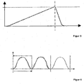
- FIG. 4 shown schematically. Shown is the position of the pressure piece on the Y axis and the time on the X axis.
- a reference profile used for the control is shown with a dashed line.
- This desired profile corresponds to the desired nominal profile, which is shown for comparison in the third cycle as a reference profile.
- the actual profile will deviate from the desired profile.
- FIG. 4 is therefore an example of an actual profile shown by a solid line. The deviations between actual and nominal profile for clarity are more pronounced than they occur in practice.
- the difference between the actual profile of the first cycle and the reference profile is subtracted from the desired profile used for the first cycle, and the difference is used as a target profile for the control during the second cycle.
- the so-obtained target profile is shown in dashed lines in the second cycle.
- the actual profile deviates to the same extent from the desired profile used, as was observed in the first cycle. This results in an actual profile (drawn with a solid line in the second cycle), which corresponds to the reference profile.
- the position of the displacement element or the speed and acceleration of the displacement element derived therefrom and the pressure in the metering space which can be determined via the force exerted by the membrane on the delivery fluid, serve as measured variables or external variables to be determined.
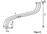
- the suction line consists of a hose which connects the suction valve with a reservoir can, for the suction stroke, ie while the pressure valve is closed and the suction valve is opened, the hydraulic system will be described in simplified FIG. 5 is shown.
- the suction line consists of a hose with the diameter D S and the hose length L.
- the hose bridges a height difference Z.
- the non-linear Navier-Stokes equations can be simplified if it is assumed that the suction line has a constant diameter and is not stretchable and that an incompressible fluid is used.
- the hydraulic parameters are now determined, which can best describe the measured or specific position of the pressure piece and the measured or specific pressure in the dosing chamber on the basis of the established model.
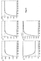
- FIGS. 6a to 6e Here, using the example of glycerol as conveying fluid, a hydraulic parameter (dotted line) as well as the values resulting from the method according to the invention (solid line) over time are shown.
- the parameters determined by the method according to the invention can in turn be used, together with the established physical model, to determine the force exerted by the hydraulic system on the pressure piece.
- This information can be used for the regulation according to the invention.
- the developed hydraulic model can physically map the influence of the hydraulic system and take this into account in the form of feedforward control.
Applications Claiming Priority (2)
| Application Number | Priority Date | Filing Date | Title |
|---|---|---|---|
| DE102013109410.4A DE102013109410A1 (de) | 2013-08-29 | 2013-08-29 | Verfahren zur Bestimmung einer physikalischen Größe in einer Verdrängerpumpe |
| PCT/EP2014/067816 WO2015028385A1 (de) | 2013-08-29 | 2014-08-21 | VERFAHREN ZUR BESTIMMUNG EINER PHYSIKALISCHEN GRÖßE IN EINER VERDRÄNGERPUMPE |
Publications (2)
| Publication Number | Publication Date |
|---|---|
| EP3039287A1 EP3039287A1 (de) | 2016-07-06 |
| EP3039287B1 true EP3039287B1 (de) | 2019-09-25 |
Family
ID=51398614
Family Applications (1)
| Application Number | Title | Priority Date | Filing Date |
|---|---|---|---|
| EP14755358.0A Active EP3039287B1 (de) | 2013-08-29 | 2014-08-21 | Verfahren zur bestimmung einer physikalischen grösse in einer verdrängerpumpe |
Country Status (8)
| Country | Link |
|---|---|
| US (1) | US20160177937A1 (fi) |
| EP (1) | EP3039287B1 (fi) |
| JP (1) | JP6234584B2 (fi) |
| KR (1) | KR20160046888A (fi) |
| CN (1) | CN105492768B (fi) |
| CA (1) | CA2921877C (fi) |
| DE (1) | DE102013109410A1 (fi) |
| WO (1) | WO2015028385A1 (fi) |
Families Citing this family (11)
| Publication number | Priority date | Publication date | Assignee | Title |
|---|---|---|---|---|
| DE102013109411A1 (de) * | 2013-08-29 | 2015-03-05 | Prominent Gmbh | Verfahren zur Bestimmung von hydraulischen Parametern |
| DE102013109412A1 (de) * | 2013-08-29 | 2015-03-05 | Prominent Gmbh | Verfahren zur Verbesserung von Dosierprofilen von Verdrängerpumpen |
| SG11201704255WA (en) | 2014-12-22 | 2017-07-28 | Smith & Nephew | Negative pressure wound therapy apparatus and methods |
| EP3544658A1 (en) * | 2016-11-22 | 2019-10-02 | Sorrel Medical Ltd. | Apparatus for delivering a therapeutic substance |
| US10995746B2 (en) | 2017-01-17 | 2021-05-04 | Innio Jenbacher Gmbh & Co Og | Two-stage reciprocating compressor optimization control system |
| EP3486482B1 (en) * | 2017-11-17 | 2021-12-08 | Artemis Intelligent Power Limited | Measuring hydraulic fluid pressure in a fluid-working machine |
| EP3591226B1 (en) * | 2018-07-06 | 2022-02-16 | Grundfos Holding A/S | Metering pump and method for controlling a metering pump |
| US11357909B2 (en) | 2018-10-05 | 2022-06-14 | Eitan Medical Ltd. | Triggering sequence |
| EP3705148A1 (en) | 2019-03-04 | 2020-09-09 | Avoset Health Ltd. | In cycle pressure measurement |
| EP4108916A1 (en) * | 2021-06-25 | 2022-12-28 | Grundfos Holding A/S | Monitoring method for monitoring the operation of a dosing pump and dosing pump system |
| DE102022207806A1 (de) | 2022-07-28 | 2024-02-08 | Prognost Systems Gmbh | Verfahren zur automatischen Überwachung einer Kolbenmaschine, nach dem Verfahren überwachbare Kolbenmaschine und Computerprogramm mit einer Implementation des Verfahrens |
Citations (3)
| Publication number | Priority date | Publication date | Assignee | Title |
|---|---|---|---|---|
| EP1757809A1 (de) | 2005-08-22 | 2007-02-28 | ProMinent Dosiertechnik GmbH | Bewegungs- und geschwindigkeitsgeregelte Magnetdosierpumpe |
| DE102008064491A1 (de) | 2008-12-23 | 2010-06-24 | Kaeser Kompressoren Gmbh | Simulationsgestütztes Verfahren zur Steuerung bzw. Regelung von Druckluftstationen |
| EP2557287A2 (de) | 2011-08-12 | 2013-02-13 | Emitec Gesellschaft für Emissionstechnologie mbH | Verfahren zur Dosierung eines Reduktionsmittels |
Family Cites Families (12)
| Publication number | Priority date | Publication date | Assignee | Title |
|---|---|---|---|---|
| US5197859A (en) * | 1970-11-29 | 1993-03-30 | Siff Elliott J | Well pump system |
| DE19828553C1 (de) * | 1998-06-26 | 2000-02-03 | Bosch Gmbh Robert | Verfahren und Vorrichtungen zur Durchführung eines Verfahrens zur Bildung oder Anpassung eines Ansteuersignals zur Ansteuerung eines ein Druckmedium fördernden Mittels eines Fahrzeugbremssystems |
| DE19842565B4 (de) * | 1998-09-03 | 2005-08-25 | Ksb Ag | Automatische Ermittlung der PID-Reglerparameter für einen Druckregelkreis in Mehrpumpenanlagen |
| DE202005001746U1 (de) * | 2004-08-20 | 2005-12-22 | Nash-Elmo Industries Gmbh | Vorrichtung zum Steuern einer Strömungsarbeitsmaschine |
| US8079825B2 (en) * | 2006-02-21 | 2011-12-20 | International Rectifier Corporation | Sensor-less control method for linear compressors |
| JP4476314B2 (ja) * | 2007-08-10 | 2010-06-09 | 三洋電機株式会社 | モータ制御装置及び圧縮機 |
| DE102008030544B4 (de) * | 2008-06-27 | 2014-05-22 | Siemens Aktiengesellschaft | Modellbasiertes Verfahren zur Überwachung von mikromechanischen Pumpen |
| EP2357363B8 (de) * | 2010-02-12 | 2012-06-06 | Allweiler GmbH | Betriebssteuerungsvorrichtung für eine Verdrängerpumpe, Pumpensystem und Verfahren zum Betreiben eines solchen |
| MX2012013396A (es) * | 2010-05-18 | 2013-06-28 | Electrolux Ab | Dispositivo de dosificacion alimentadfo por bateria. |
| DE102010049071A1 (de) * | 2010-10-20 | 2012-04-26 | Emitec Gesellschaft Für Emissionstechnologie Mbh | Verfahren zum Betrieb einer Dosiervorrichtung |
| WO2012066090A1 (de) * | 2010-11-17 | 2012-05-24 | Ksb Aktiengesellschaft | Verfahren und regelvorrichtung zur drehzahlvariablen regelung eines verdrängerpumpenaggregates sowie verdrängerpumpenanordnung |
| DE102011115650B4 (de) * | 2011-09-28 | 2022-03-03 | Robert Bosch Gmbh | Verfahren zur Diagnose des Zustandes einer hydrostatischen Verdrängermaschine und hydraulische Anordnung mit hydrostatischer Verdrängermaschine |
-
2013
- 2013-08-29 DE DE102013109410.4A patent/DE102013109410A1/de not_active Withdrawn
-
2014
- 2014-08-21 WO PCT/EP2014/067816 patent/WO2015028385A1/de active Application Filing
- 2014-08-21 US US14/907,851 patent/US20160177937A1/en not_active Abandoned
- 2014-08-21 CN CN201480047895.2A patent/CN105492768B/zh active Active
- 2014-08-21 CA CA2921877A patent/CA2921877C/en active Active
- 2014-08-21 JP JP2016537237A patent/JP6234584B2/ja active Active
- 2014-08-21 KR KR1020167007823A patent/KR20160046888A/ko not_active Application Discontinuation
- 2014-08-21 EP EP14755358.0A patent/EP3039287B1/de active Active
Patent Citations (3)
| Publication number | Priority date | Publication date | Assignee | Title |
|---|---|---|---|---|
| EP1757809A1 (de) | 2005-08-22 | 2007-02-28 | ProMinent Dosiertechnik GmbH | Bewegungs- und geschwindigkeitsgeregelte Magnetdosierpumpe |
| DE102008064491A1 (de) | 2008-12-23 | 2010-06-24 | Kaeser Kompressoren Gmbh | Simulationsgestütztes Verfahren zur Steuerung bzw. Regelung von Druckluftstationen |
| EP2557287A2 (de) | 2011-08-12 | 2013-02-13 | Emitec Gesellschaft für Emissionstechnologie mbH | Verfahren zur Dosierung eines Reduktionsmittels |
Non-Patent Citations (3)
| Title |
|---|
| FALCO HAUS: "Methoden zur Störungsfrüherkennung an oszillierenden Verdrängerpumpen", FORTSCHR.-BER. VDI REIHE, vol. 8, no. 1109, 1 January 2006 (2006-01-01), pages 52 - 59, XP055757014 |
| MING-FA FENG: "dissweration of the faculty of the Virginia Polytechnic Institute", FAULT DIAGNOSIS AND PREDICTION IN RECIPROCATING AIR COMPRESSORS BY QUANTIFYING OPERATING PARAMETERS, 5 March 1992 (1992-03-05), pages 1 - 223 |
| R. ISERMANN: "Fault-Diagnosis Applications", BUCHVERÖFFENTLICHUNG, 2011, pages 1 - 192 |
Also Published As
| Publication number | Publication date |
|---|---|
| US20160177937A1 (en) | 2016-06-23 |
| EP3039287A1 (de) | 2016-07-06 |
| JP2016530444A (ja) | 2016-09-29 |
| KR20160046888A (ko) | 2016-04-29 |
| DE102013109410A1 (de) | 2015-03-19 |
| CA2921877C (en) | 2021-05-04 |
| CN105492768B (zh) | 2019-05-03 |
| WO2015028385A1 (de) | 2015-03-05 |
| CN105492768A (zh) | 2016-04-13 |
| CA2921877A1 (en) | 2015-03-05 |
| JP6234584B2 (ja) | 2017-11-22 |
Similar Documents
| Publication | Publication Date | Title |
|---|---|---|
| EP3039287B1 (de) | Verfahren zur bestimmung einer physikalischen grösse in einer verdrängerpumpe | |
| EP3039289B1 (de) | Verfahren zur bestimmung von hydraulischen parametern in einer verdrängerpumpe | |
| DE602004012500T2 (de) | Verfahren zur Diagnose eines zyklischen Systems | |
| DE102011011262B4 (de) | Vorrichtung zum Schätzen einer Kupplungskolbenstellung | |
| EP3039288B1 (de) | Verfahren zur verbesserung von dosierprofilen von verdrängerpumpen | |
| DE102014206442A1 (de) | Verfahren und Vorrichtung zum Betreiben eines Druckspeichers, insbesondere für Common-Rail-Einspritzsysteme in der Kfz-Technik | |
| DE102018216338A1 (de) | Diagnoseeinrichtung, System und Verfahren | |
| DE102017213650A1 (de) | Verfahren zum Regeln eines hydraulischen Systems, Regeleinheit für ein hydraulisches System und hydraulisches System | |
| DE102017122373A1 (de) | Betriebszustandsüberwachungsvorrichtung für einen Zylinder | |
| WO2022078758A1 (de) | Verfahren zur feststellung von leckagen einer verdrängerpumpe | |
| DE102016214708A1 (de) | Stetigventileinheit, hydraulische Achse und Verfahren zum Betreiben einer hydraulischen Achse | |
| DE102016103624A1 (de) | Steuerung einer CVT-Übersetzungsverhältnisänderung während eines plötzlichen Fahrzeugstopps | |
| DE102015225999A1 (de) | Verfahren zum Überprüfen des Zustandes eines Ventils | |
| EP3308236B1 (de) | Druckregelvorrichtung | |
| DE102018219365A1 (de) | Hydromaschine, Steuerungsanordnung, Hydraulisches System und Verfahren | |
| EP3121672B1 (de) | Diagnoseeinrichtung und verfahren zur überwachung des betriebs eines regelkreises | |
| DE102013006220B4 (de) | Pneumatischer Antrieb und Verfahren zur Erfassung der Leistung eines pneumatischen Antriebs | |
| DE102016201988B3 (de) | Verfahren zum Ermitteln eines Funktionszustands eines Antriebssystems und Antriebssystem | |
| DE102004040210A1 (de) | Hydraulischer Steller für ein Gaswechselventil einer Brennkraftmaschine | |
| DE102015224650A1 (de) | Verfahren und System zum Ermitteln von Systemgrößen einer Axialkolbenmaschine | |
| EP2836879B1 (de) | Regeleinrichtung für eine hydraulikzylindereinheit mit einzelventilsteuerung | |
| EP3252547B1 (de) | Verfahren zum steuern einer bewegung eines beweglich gelagerten körpers eines mechanischen systems | |
| DE102014202558A1 (de) | Digitalhydraulischer druckregler und überprüfungsverfahren eines digitalhydraulischen druckreglers | |
| DE102016209385A1 (de) | Verfahren zum Regeln eines hydraulischen Druckbegrenzungsventils, Sliding-Mode-Regler und Verfahren zum Einstellen eines Stellgesetzes und einer Schaltfunktion | |
| DE102015216116B3 (de) | Verfahren zur Ansteuerung einer Ventilanordnung und fluidisches System |
Legal Events
| Date | Code | Title | Description |
|---|---|---|---|
| PUAI | Public reference made under article 153(3) epc to a published international application that has entered the european phase |
Free format text: ORIGINAL CODE: 0009012 |
|
| 17P | Request for examination filed |
Effective date: 20160229 |
|
| AK | Designated contracting states |
Kind code of ref document: A1 Designated state(s): AL AT BE BG CH CY CZ DE DK EE ES FI FR GB GR HR HU IE IS IT LI LT LU LV MC MK MT NL NO PL PT RO RS SE SI SK SM TR |
|
| AX | Request for extension of the european patent |
Extension state: BA ME |
|
| DAX | Request for extension of the european patent (deleted) | ||
| STAA | Information on the status of an ep patent application or granted ep patent |
Free format text: STATUS: EXAMINATION IS IN PROGRESS |
|
| 17Q | First examination report despatched |
Effective date: 20190104 |
|
| REG | Reference to a national code |
Ref country code: DE Ref legal event code: R079 Ref document number: 502014012723 Country of ref document: DE Free format text: PREVIOUS MAIN CLASS: F04B0017040000 Ipc: F04B0049020000 |
|
| GRAP | Despatch of communication of intention to grant a patent |
Free format text: ORIGINAL CODE: EPIDOSNIGR1 |
|
| RIC1 | Information provided on ipc code assigned before grant |
Ipc: F04B 49/06 20060101ALI20190326BHEP Ipc: F15B 19/00 20060101ALI20190326BHEP Ipc: F04B 49/02 20060101AFI20190326BHEP Ipc: G05B 13/04 20060101ALI20190326BHEP Ipc: F04B 51/00 20060101ALI20190326BHEP Ipc: F04B 43/04 20060101ALI20190326BHEP Ipc: F04B 53/10 20060101ALI20190326BHEP Ipc: F04B 49/20 20060101ALI20190326BHEP Ipc: F04B 17/04 20060101ALI20190326BHEP |
|
| STAA | Information on the status of an ep patent application or granted ep patent |
Free format text: STATUS: GRANT OF PATENT IS INTENDED |
|
| INTG | Intention to grant announced |
Effective date: 20190502 |
|
| GRAS | Grant fee paid |
Free format text: ORIGINAL CODE: EPIDOSNIGR3 |
|
| GRAA | (expected) grant |
Free format text: ORIGINAL CODE: 0009210 |
|
| STAA | Information on the status of an ep patent application or granted ep patent |
Free format text: STATUS: THE PATENT HAS BEEN GRANTED |
|
| AK | Designated contracting states |
Kind code of ref document: B1 Designated state(s): AL AT BE BG CH CY CZ DE DK EE ES FI FR GB GR HR HU IE IS IT LI LT LU LV MC MK MT NL NO PL PT RO RS SE SI SK SM TR |
|
| REG | Reference to a national code |
Ref country code: GB Ref legal event code: FG4D Free format text: NOT ENGLISH |
|
| REG | Reference to a national code |
Ref country code: CH Ref legal event code: EP |
|
| REG | Reference to a national code |
Ref country code: AT Ref legal event code: REF Ref document number: 1184073 Country of ref document: AT Kind code of ref document: T Effective date: 20191015 |
|
| REG | Reference to a national code |
Ref country code: IE Ref legal event code: FG4D Free format text: LANGUAGE OF EP DOCUMENT: GERMAN |
|
| REG | Reference to a national code |
Ref country code: DE Ref legal event code: R096 Ref document number: 502014012723 Country of ref document: DE |
|
| REG | Reference to a national code |
Ref country code: NL Ref legal event code: MP Effective date: 20190925 |
|
| PG25 | Lapsed in a contracting state [announced via postgrant information from national office to epo] |
Ref country code: FI Free format text: LAPSE BECAUSE OF FAILURE TO SUBMIT A TRANSLATION OF THE DESCRIPTION OR TO PAY THE FEE WITHIN THE PRESCRIBED TIME-LIMIT Effective date: 20190925 Ref country code: LT Free format text: LAPSE BECAUSE OF FAILURE TO SUBMIT A TRANSLATION OF THE DESCRIPTION OR TO PAY THE FEE WITHIN THE PRESCRIBED TIME-LIMIT Effective date: 20190925 Ref country code: BG Free format text: LAPSE BECAUSE OF FAILURE TO SUBMIT A TRANSLATION OF THE DESCRIPTION OR TO PAY THE FEE WITHIN THE PRESCRIBED TIME-LIMIT Effective date: 20191225 Ref country code: NO Free format text: LAPSE BECAUSE OF FAILURE TO SUBMIT A TRANSLATION OF THE DESCRIPTION OR TO PAY THE FEE WITHIN THE PRESCRIBED TIME-LIMIT Effective date: 20191225 Ref country code: SE Free format text: LAPSE BECAUSE OF FAILURE TO SUBMIT A TRANSLATION OF THE DESCRIPTION OR TO PAY THE FEE WITHIN THE PRESCRIBED TIME-LIMIT Effective date: 20190925 Ref country code: HR Free format text: LAPSE BECAUSE OF FAILURE TO SUBMIT A TRANSLATION OF THE DESCRIPTION OR TO PAY THE FEE WITHIN THE PRESCRIBED TIME-LIMIT Effective date: 20190925 |
|
| REG | Reference to a national code |
Ref country code: LT Ref legal event code: MG4D |
|
| PG25 | Lapsed in a contracting state [announced via postgrant information from national office to epo] |
Ref country code: RS Free format text: LAPSE BECAUSE OF FAILURE TO SUBMIT A TRANSLATION OF THE DESCRIPTION OR TO PAY THE FEE WITHIN THE PRESCRIBED TIME-LIMIT Effective date: 20190925 Ref country code: GR Free format text: LAPSE BECAUSE OF FAILURE TO SUBMIT A TRANSLATION OF THE DESCRIPTION OR TO PAY THE FEE WITHIN THE PRESCRIBED TIME-LIMIT Effective date: 20191226 Ref country code: LV Free format text: LAPSE BECAUSE OF FAILURE TO SUBMIT A TRANSLATION OF THE DESCRIPTION OR TO PAY THE FEE WITHIN THE PRESCRIBED TIME-LIMIT Effective date: 20190925 |
|
| PG25 | Lapsed in a contracting state [announced via postgrant information from national office to epo] |
Ref country code: PL Free format text: LAPSE BECAUSE OF FAILURE TO SUBMIT A TRANSLATION OF THE DESCRIPTION OR TO PAY THE FEE WITHIN THE PRESCRIBED TIME-LIMIT Effective date: 20190925 Ref country code: EE Free format text: LAPSE BECAUSE OF FAILURE TO SUBMIT A TRANSLATION OF THE DESCRIPTION OR TO PAY THE FEE WITHIN THE PRESCRIBED TIME-LIMIT Effective date: 20190925 Ref country code: AL Free format text: LAPSE BECAUSE OF FAILURE TO SUBMIT A TRANSLATION OF THE DESCRIPTION OR TO PAY THE FEE WITHIN THE PRESCRIBED TIME-LIMIT Effective date: 20190925 Ref country code: IT Free format text: LAPSE BECAUSE OF FAILURE TO SUBMIT A TRANSLATION OF THE DESCRIPTION OR TO PAY THE FEE WITHIN THE PRESCRIBED TIME-LIMIT Effective date: 20190925 Ref country code: ES Free format text: LAPSE BECAUSE OF FAILURE TO SUBMIT A TRANSLATION OF THE DESCRIPTION OR TO PAY THE FEE WITHIN THE PRESCRIBED TIME-LIMIT Effective date: 20190925 Ref country code: RO Free format text: LAPSE BECAUSE OF FAILURE TO SUBMIT A TRANSLATION OF THE DESCRIPTION OR TO PAY THE FEE WITHIN THE PRESCRIBED TIME-LIMIT Effective date: 20190925 Ref country code: PT Free format text: LAPSE BECAUSE OF FAILURE TO SUBMIT A TRANSLATION OF THE DESCRIPTION OR TO PAY THE FEE WITHIN THE PRESCRIBED TIME-LIMIT Effective date: 20200127 Ref country code: NL Free format text: LAPSE BECAUSE OF FAILURE TO SUBMIT A TRANSLATION OF THE DESCRIPTION OR TO PAY THE FEE WITHIN THE PRESCRIBED TIME-LIMIT Effective date: 20190925 |
|
| PG25 | Lapsed in a contracting state [announced via postgrant information from national office to epo] |
Ref country code: SM Free format text: LAPSE BECAUSE OF FAILURE TO SUBMIT A TRANSLATION OF THE DESCRIPTION OR TO PAY THE FEE WITHIN THE PRESCRIBED TIME-LIMIT Effective date: 20190925 Ref country code: SK Free format text: LAPSE BECAUSE OF FAILURE TO SUBMIT A TRANSLATION OF THE DESCRIPTION OR TO PAY THE FEE WITHIN THE PRESCRIBED TIME-LIMIT Effective date: 20190925 Ref country code: CZ Free format text: LAPSE BECAUSE OF FAILURE TO SUBMIT A TRANSLATION OF THE DESCRIPTION OR TO PAY THE FEE WITHIN THE PRESCRIBED TIME-LIMIT Effective date: 20190925 Ref country code: IS Free format text: LAPSE BECAUSE OF FAILURE TO SUBMIT A TRANSLATION OF THE DESCRIPTION OR TO PAY THE FEE WITHIN THE PRESCRIBED TIME-LIMIT Effective date: 20200224 |
|
| REG | Reference to a national code |
Ref country code: DE Ref legal event code: R026 Ref document number: 502014012723 Country of ref document: DE |
|
| PLBI | Opposition filed |
Free format text: ORIGINAL CODE: 0009260 |
|
| PLAX | Notice of opposition and request to file observation + time limit sent |
Free format text: ORIGINAL CODE: EPIDOSNOBS2 |
|
| 26 | Opposition filed |
Opponent name: KNF FLODOS AG Effective date: 20200617 |
|
| PG2D | Information on lapse in contracting state deleted |
Ref country code: IS |
|
| PG25 | Lapsed in a contracting state [announced via postgrant information from national office to epo] |
Ref country code: DK Free format text: LAPSE BECAUSE OF FAILURE TO SUBMIT A TRANSLATION OF THE DESCRIPTION OR TO PAY THE FEE WITHIN THE PRESCRIBED TIME-LIMIT Effective date: 20190925 Ref country code: IS Free format text: LAPSE BECAUSE OF FAILURE TO SUBMIT A TRANSLATION OF THE DESCRIPTION OR TO PAY THE FEE WITHIN THE PRESCRIBED TIME-LIMIT Effective date: 20200126 |
|
| PLBB | Reply of patent proprietor to notice(s) of opposition received |
Free format text: ORIGINAL CODE: EPIDOSNOBS3 |
|
| PG25 | Lapsed in a contracting state [announced via postgrant information from national office to epo] |
Ref country code: SI Free format text: LAPSE BECAUSE OF FAILURE TO SUBMIT A TRANSLATION OF THE DESCRIPTION OR TO PAY THE FEE WITHIN THE PRESCRIBED TIME-LIMIT Effective date: 20190925 |
|
| PG25 | Lapsed in a contracting state [announced via postgrant information from national office to epo] |
Ref country code: MC Free format text: LAPSE BECAUSE OF FAILURE TO SUBMIT A TRANSLATION OF THE DESCRIPTION OR TO PAY THE FEE WITHIN THE PRESCRIBED TIME-LIMIT Effective date: 20190925 |
|
| REG | Reference to a national code |
Ref country code: CH Ref legal event code: PL |
|
| GBPC | Gb: european patent ceased through non-payment of renewal fee |
Effective date: 20200821 |
|
| PG25 | Lapsed in a contracting state [announced via postgrant information from national office to epo] |
Ref country code: LI Free format text: LAPSE BECAUSE OF NON-PAYMENT OF DUE FEES Effective date: 20200831 Ref country code: CH Free format text: LAPSE BECAUSE OF NON-PAYMENT OF DUE FEES Effective date: 20200831 Ref country code: LU Free format text: LAPSE BECAUSE OF NON-PAYMENT OF DUE FEES Effective date: 20200821 |
|
| REG | Reference to a national code |
Ref country code: BE Ref legal event code: MM Effective date: 20200831 |
|
| PG25 | Lapsed in a contracting state [announced via postgrant information from national office to epo] |
Ref country code: FR Free format text: LAPSE BECAUSE OF NON-PAYMENT OF DUE FEES Effective date: 20200831 |
|
| PLBP | Opposition withdrawn |
Free format text: ORIGINAL CODE: 0009264 |
|
| PG25 | Lapsed in a contracting state [announced via postgrant information from national office to epo] |
Ref country code: BE Free format text: LAPSE BECAUSE OF NON-PAYMENT OF DUE FEES Effective date: 20200831 Ref country code: IE Free format text: LAPSE BECAUSE OF NON-PAYMENT OF DUE FEES Effective date: 20200821 Ref country code: GB Free format text: LAPSE BECAUSE OF NON-PAYMENT OF DUE FEES Effective date: 20200821 |
|
| PLBD | Termination of opposition procedure: decision despatched |
Free format text: ORIGINAL CODE: EPIDOSNOPC1 |
|
| REG | Reference to a national code |
Ref country code: AT Ref legal event code: MM01 Ref document number: 1184073 Country of ref document: AT Kind code of ref document: T Effective date: 20200821 |
|
| PG25 | Lapsed in a contracting state [announced via postgrant information from national office to epo] |
Ref country code: AT Free format text: LAPSE BECAUSE OF NON-PAYMENT OF DUE FEES Effective date: 20200821 |
|
| REG | Reference to a national code |
Ref country code: DE Ref legal event code: R100 Ref document number: 502014012723 Country of ref document: DE |
|
| PLBM | Termination of opposition procedure: date of legal effect published |
Free format text: ORIGINAL CODE: 0009276 |
|
| 27C | Opposition proceedings terminated |
Effective date: 20211031 |
|
| PG25 | Lapsed in a contracting state [announced via postgrant information from national office to epo] |
Ref country code: TR Free format text: LAPSE BECAUSE OF FAILURE TO SUBMIT A TRANSLATION OF THE DESCRIPTION OR TO PAY THE FEE WITHIN THE PRESCRIBED TIME-LIMIT Effective date: 20190925 Ref country code: MT Free format text: LAPSE BECAUSE OF FAILURE TO SUBMIT A TRANSLATION OF THE DESCRIPTION OR TO PAY THE FEE WITHIN THE PRESCRIBED TIME-LIMIT Effective date: 20190925 Ref country code: CY Free format text: LAPSE BECAUSE OF FAILURE TO SUBMIT A TRANSLATION OF THE DESCRIPTION OR TO PAY THE FEE WITHIN THE PRESCRIBED TIME-LIMIT Effective date: 20190925 |
|
| PG25 | Lapsed in a contracting state [announced via postgrant information from national office to epo] |
Ref country code: MK Free format text: LAPSE BECAUSE OF FAILURE TO SUBMIT A TRANSLATION OF THE DESCRIPTION OR TO PAY THE FEE WITHIN THE PRESCRIBED TIME-LIMIT Effective date: 20190925 |
|
| PGFP | Annual fee paid to national office [announced via postgrant information from national office to epo] |
Ref country code: DE Payment date: 20230822 Year of fee payment: 10 |