EP3038768B1 - Machine servant a faconner des corps de boites de conserve avec mécanisme et conception pour prévenir l'affaissement de piston - Google Patents
Machine servant a faconner des corps de boites de conserve avec mécanisme et conception pour prévenir l'affaissement de piston Download PDFInfo
- Publication number
- EP3038768B1 EP3038768B1 EP14839038.8A EP14839038A EP3038768B1 EP 3038768 B1 EP3038768 B1 EP 3038768B1 EP 14839038 A EP14839038 A EP 14839038A EP 3038768 B1 EP3038768 B1 EP 3038768B1
- Authority
- EP
- European Patent Office
- Prior art keywords
- assembly
- ram
- ram body
- tension
- coupling
- Prior art date
- Legal status (The legal status is an assumption and is not a legal conclusion. Google has not performed a legal analysis and makes no representation as to the accuracy of the status listed.)
- Active
Links
- 230000007246 mechanism Effects 0.000 title claims description 7
- 230000008878 coupling Effects 0.000 claims description 119
- 238000010168 coupling process Methods 0.000 claims description 119
- 238000005859 coupling reaction Methods 0.000 claims description 119
- 239000012530 fluid Substances 0.000 description 39
- 230000002706 hydrostatic effect Effects 0.000 description 24
- 230000000712 assembly Effects 0.000 description 23
- 238000000429 assembly Methods 0.000 description 23
- 239000000314 lubricant Substances 0.000 description 17
- 238000010409 ironing Methods 0.000 description 9
- 239000012809 cooling fluid Substances 0.000 description 7
- 229910052782 aluminium Inorganic materials 0.000 description 6
- XAGFODPZIPBFFR-UHFFFAOYSA-N aluminium Chemical compound [Al] XAGFODPZIPBFFR-UHFFFAOYSA-N 0.000 description 6
- XEEYBQQBJWHFJM-UHFFFAOYSA-N Iron Chemical compound [Fe] XEEYBQQBJWHFJM-UHFFFAOYSA-N 0.000 description 4
- 229910000831 Steel Inorganic materials 0.000 description 4
- 238000000034 method Methods 0.000 description 4
- 230000009467 reduction Effects 0.000 description 4
- 239000010959 steel Substances 0.000 description 4
- 230000008859 change Effects 0.000 description 3
- 238000004891 communication Methods 0.000 description 3
- 229920000049 Carbon (fiber) Polymers 0.000 description 2
- 239000004917 carbon fiber Substances 0.000 description 2
- 239000000945 filler Substances 0.000 description 2
- 229910052742 iron Inorganic materials 0.000 description 2
- 230000001050 lubricating effect Effects 0.000 description 2
- VNWKTOKETHGBQD-UHFFFAOYSA-N methane Chemical group C VNWKTOKETHGBQD-UHFFFAOYSA-N 0.000 description 2
- 230000008569 process Effects 0.000 description 2
- 230000003068 static effect Effects 0.000 description 2
- UONOETXJSWQNOL-UHFFFAOYSA-N tungsten carbide Chemical compound [W+]#[C-] UONOETXJSWQNOL-UHFFFAOYSA-N 0.000 description 2
- 238000011144 upstream manufacturing Methods 0.000 description 2
- 239000002826 coolant Substances 0.000 description 1
- 238000001816 cooling Methods 0.000 description 1
- 239000000110 cooling liquid Substances 0.000 description 1
- 238000012864 cross contamination Methods 0.000 description 1
- 230000007423 decrease Effects 0.000 description 1
- 230000009977 dual effect Effects 0.000 description 1
- 230000000694 effects Effects 0.000 description 1
- 229910052751 metal Inorganic materials 0.000 description 1
- 239000002184 metal Substances 0.000 description 1
- 239000000203 mixture Substances 0.000 description 1
- 238000012986 modification Methods 0.000 description 1
- 230000004048 modification Effects 0.000 description 1
- 238000007639 printing Methods 0.000 description 1
- 238000004904 shortening Methods 0.000 description 1
- 230000007704 transition Effects 0.000 description 1
- 238000009966 trimming Methods 0.000 description 1
- 238000005406 washing Methods 0.000 description 1
Images


Classifications
-
- B—PERFORMING OPERATIONS; TRANSPORTING
- B21—MECHANICAL METAL-WORKING WITHOUT ESSENTIALLY REMOVING MATERIAL; PUNCHING METAL
- B21D—WORKING OR PROCESSING OF SHEET METAL OR METAL TUBES, RODS OR PROFILES WITHOUT ESSENTIALLY REMOVING MATERIAL; PUNCHING METAL
- B21D22/00—Shaping without cutting, by stamping, spinning, or deep-drawing
- B21D22/20—Deep-drawing
- B21D22/28—Deep-drawing of cylindrical articles using consecutive dies
-
- B—PERFORMING OPERATIONS; TRANSPORTING
- B21—MECHANICAL METAL-WORKING WITHOUT ESSENTIALLY REMOVING MATERIAL; PUNCHING METAL
- B21D—WORKING OR PROCESSING OF SHEET METAL OR METAL TUBES, RODS OR PROFILES WITHOUT ESSENTIALLY REMOVING MATERIAL; PUNCHING METAL
- B21D37/00—Tools as parts of machines covered by this subclass
- B21D37/10—Die sets; Pillar guides
- B21D37/12—Particular guiding equipment, e.g. pliers; Special arrangements for interconnection or cooperation of dies
-
- B—PERFORMING OPERATIONS; TRANSPORTING
- B21—MECHANICAL METAL-WORKING WITHOUT ESSENTIALLY REMOVING MATERIAL; PUNCHING METAL
- B21D—WORKING OR PROCESSING OF SHEET METAL OR METAL TUBES, RODS OR PROFILES WITHOUT ESSENTIALLY REMOVING MATERIAL; PUNCHING METAL
- B21D51/00—Making hollow objects
- B21D51/16—Making hollow objects characterised by the use of the objects
- B21D51/26—Making hollow objects characterised by the use of the objects cans or tins; Closing same in a permanent manner
Definitions
- the disclosed and claimed concept relates to a can bodymaker as defined in the preamble of claim 1, as for example known from US 4 935 167 A .
- 1 inch or 1" corresponds to 25.4 mm and 1 fluid ounce corresponds to 29.57 ml.
- an aluminum can begins as a disk of aluminum, also known as a "blank,” that is punched from a sheet or coil of aluminum. That is, the sheet is fed into a dual action press where a "blank” disc is cut from the sheet by an outer slide/ram motion. An inner slide/ram then pushes the "blank” through a draw process to create a cup.
- the cup has a bottom and a depending sidewall. The cup is fed into one of several bodymakers, which perform a redraw and ironing operation. More specifically, the cup is disposed in a can forming machine at the mouth of a die pack having substantially circular openings therein.
- the cup is held in place by a redraw sleeve, which is part of the redraw assembly.
- the redraw sleeve is a hollow tubular construct that is disposed inside the cup and biases the cup against the die pack. More specifically, the first die in the die pack is the redraw die, which is not a part of the redraw assembly.
- the cup is biased against the redraw die by the redraw sleeve.
- Other dies, the ironing dies are disposed behind, and axially aligned with, the redraw die. The ironing dies and redraw die are not part of the redraw assembly.
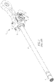
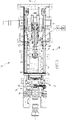
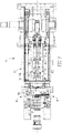
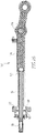
- An elongated, cylindrical ram assembly shown in Figures 1 and 1A , includes a carriage 2 that supports a ram body 3 with a punch 4 at the forward, distal end.
- the ram and punch are aligned with, and structured to travel through, the openings in the redraw die and the ironing dies.
- a domer At the end of the die pack opposite the ram is a domer.
- the domer is a die structured to form a concave dome in the bottom of the cup/can.
- a cup is disposed at one end of the die pack.
- the cup typically, has a greater diameter than a finished can as well as a greater wall thickness.
- the redraw sleeve is disposed inside of the cup and biases the cup bottom against the redraw die.
- the opening in the redraw die has a diameter that is smaller than the cup.
- the elongated ram body, and more specifically the punch passes through the hollow redraw sleeve and contacts the bottom of the cup. As the ram body continues to move forward, the cup is moved through the redraw die. As the opening in the redraw die is smaller than the original diameter of the cup, the cup is deformed and becomes elongated with a smaller diameter.
- the wall thickness of the cup typically remains the same as the cup passes through the redraw die.
- the elongated cup passes through a number of ironing dies.
- the ironing dies each thin the wall thickness of the cup causing the cup to elongate.
- the final forming of the can body occurs when the bottom of the elongated cup engages the domer, creating a concave dome in the cup bottom.
- the can body is elongated, has a thinner wall, and a domed bottom.
- the cooling fluid disposed on the surface of the ram body is substantially collected by a seal assembly disposed between a hydrostatic/hydrodynamic bearing assembly and the redraw (or hold down) assembly.
- the seal assembly includes a number of seals that conform to the cross-sectional shape of the ram body. As the ram body passes through the seal assembly, the cooling fluid is collected and recycled.
- the can body is ejected from the ram, and more specifically the punch, for further processing, such as, but not limited to trimming, washing, printing, flanging, inspecting and placed on pallets, which are shipped to the filler.
- further processing such as, but not limited to trimming, washing, printing, flanging, inspecting and placed on pallets, which are shipped to the filler.
- the cans are taken off of the pallets, filled, ends placed on them and then the filled cans are repackaged in six packs and/or twelve pack cases, etc.
- the ram body moves in a cycle many times each minute.
- the bodymaker also includes a crank assembly having a crank arm.
- the crank arm is coupled to the ram assembly and causes the ram assembly to reciprocate.
- the ram body is substantially, axially aligned with the hollow redraw sleeve and the die pack. The alignment is important because a mis-alignment causes the ram to wear on the dies and vice-versa.
- a hydrostatic/hydrodynamic guide fluid bearing assembly 5 that guides the ram body through the tooling, that is a "guide bearing.”
- hydrostatic/hydrodynamic fluid bearing assemblies 6 on the sides of the ram assembly carriage, but these bearings do not "guide” the ram.
- These hydrostatic/hydrodynamic fluid bearing assemblies 6 are disposed in channels and have ports 7, disposed on the top, side, and lower surfaces, that produce a lubricating fluid.
- the ram body also passes through a seal pack.
- Various factors, such as, but not limited to, the relatively short length of the carriage prevent these additional hydrostatic/hydrodynamic fluid bearing assemblies 6 from controlling the orientation and alignment of the ram body. That is, the small amount of "wobble" of the carriage in the channels prevents the carriage and the hydrostatic/hydrodynamic fluid bearing assemblies 6 from guiding the ram body.
- a “guide,” when used in reference to a ram body bearings, means to control the orientation and alignment of the ram body.
- a “guide bearing assembly,” as used herein, is structured to, and does, control the orientation and alignment of the ram body.
- a bearing, such as the prior art hydrostatic/hydrodynamic fluid bearing assemblies 6 on the sides of the ram assembly carriage, that have a minimal influence or are merely capable of affecting the orientation and alignment of the ram body are not “guide” bearing assemblies, as used herein.
- the guide bearing assembly is, typically, disposed immediately upstream (closer to the crank arm) of the redraw assembly.
- the fluid bearing assembly includes a body defining a passage.
- the ram body extends through the fluid bearing assembly passage.
- the fluid bearing assembly introduces a fluid, such as, but not limited to oil, between the fluid bearing assembly body and the ram body. Controlling the amount and pressure of the fluid allows for precise control over the alignment of the ram body with the hollow redraw sleeve and the die pack.
- the fluid bearing assembly fluid is collected by the seal assembly and recycled.
- the ram body must have a sufficient length not only to extend through the die pack, but the seal assembly and fluid bearing assembly; for a can body of a typical 12 fluid ounce can, the ram body has a length of between about 50 inches to 52 inches when using a 24 inch stroke for a can body of a typical 12 fluid ounce can.
- Ram lengths differ for different stroke lengths to support different size can bodies. For example, the following is a table of common ram lengths and the associated stroke.
- Ram length Range A Specific Embodiment Exemplary Stroke Length 45.0 to 46.0 Inches 45.387 Inches 18 Inches 49.0 to 51.813 Inches 50.0 Inches 22 Inches 50.0 to 52.0 Inches 51.0 Inches 24 Inches 56.0 to 58.0 Inches 57.0 Inches 30 Inches
- Ram 202 can 02.500
- Ram 211 can 02.750
- Ram 300 can 03.125”
- Ram 307 can
- a ram body of any of these dimensions is prone to damage from normal wear and tear.
- the ram body passes through a die pack in a first direction when forming a can body, and then travels back through the die pack after the can body is formed.
- the die pack in the bodymaker has multiple, spaced dies, each die having an opening. Each die opening is slightly smaller than the next adjacent upstream die. Because the openings in the subsequent dies in the die pack have a smaller inner diameter, i.e. a smaller opening, the aluminum cup is thinned as the ram moves the aluminum through the rest of the die pack.
- the space between the punch and the redraw die is typically a small clearance (0.001-2 inch per side) over metal thickness and is less than 0.004 inch in the last ironing die.
- Typical aluminum gauge used to create a typical 12 fluid ounce can is 0.0108 inch in practice today. This narrow spacing, however, is a disadvantage, especially during the return stroke.
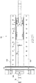
- Ram droop or deflection is inherent to this long slender horizontal ram and punch with stroke lengths varying from 22 - 30 inches and throughput frequencies ranging from 210 to 450 strokes/minute (SPM) depending on can diameter, can height and machine model.
- this ram can be visualized as a cantilever beam fixed at one end and free on the other end.
- the upper theorized beam type shows the deflection of the ram due to the tungsten carbide punch weight and the lower theorized beam type shows the deflection of the long steel ram due to its own weight.
- the total deflection of the horizontal ram in a known body maker is a combination of these two effects.
- the typical weight of the ram and punch assembly is approximately 23kg (501bf) total.
- the maximum deflection or ram droop (conceptualized as a cantilever beam) is governed by its length (l) to the fourth power for the long slender steel ram and to the third power for the heavy carbide punch at the end of the ram.
- I is the area moment of inertia, as is known. Therefore, significant reduction in deflection or ram droop can be realized if the ram could be shortened.
- the concept to outboard the hydrostatic/hydrodynamic ram bearings from the main ram itself is essential to shortening the length of the ram because the ram no longer requires additional length to be supported by the bearing through the can body making process.
- Ram droop is a problem on the return stroke where a can is not being formed. In the return stroke, the punch and ram have more of a tendency to contact the tooling causing wear and damage. A significant contributor to this is contact between the punch and the ironing dies (primarily third iron or end iron) on the return stroke of the machine.
- a ram body passes through a hydrostatic/hydrodynamic fluid bearing assembly.
- the hydrostatic/hydrodynamic fluid bearing assembly is fixed to a bulkhead in the can bodymaker housing assembly. This means that the length of the cantilevered portion of the ram body changes during the body making cycle. That is, when the ram body is in a retracted, first position, the length of the cantilevered portion of the ram body is relatively short. Conversely, when the ram body is in an extended, second position, the length of the cantilevered portion of the ram body is relatively long.
- the dynamic nature of the length of the cantilevered portion of the ram body means that the amount of droop changes dynamically as well. This means that a system to compensate for the ram droop would have to be a dynamic system as well.
- the can bodymaker may comprise a ram assembly with a ram body having a diameter of about 2.0 to 2.5 inches e.g., for a typical 12 fluid oz. can, and a length of between about 30.0 inches and 32.0 inches, or about 31.0 inches.
- the ram body has a length of between about 33.0 inches to about 36.0 inches, or about 34.5 inches.
- the ram body has a diameter of about 2.0 to about 3.125 inches, or about 2.5 inches, for a typical 12 fluid oz. can.
- a can bodymaker ram assembly in another embodiment, includes an outboard guide bearing assembly.
- the outboard guide bearing assembly is "outboard;” that is, as used herein, spaced, from the ram body.
- the outboard guide bearing assembly includes a carriage assembly and a bearing assembly.
- the bearing assembly in an exemplary embodiment, includes two bearings disposed on the lateral sides of the carriage assembly.
- the bearing assemblies are hydrostatic/hydrodynamic bearing assemblies. Use of an outboard guide bearing assembly allows for a shorter ram body in that the ram body does not need to extend through a bearing assembly as well as the die pack.
- a can bodymaker ram assembly in another embodiment, includes an elongated, generally hollow ram body and a tension assembly.
- the ram body includes a proximal end, a medial portion, and a distal end.
- the tension assembly includes an elongated support member.
- the tension assembly support member includes a proximal end and a distal end. The tension assembly support member is substantially disposed within the ram body with the tension assembly support member proximal end coupled to the ram body proximal end, and the tension assembly support member distal end coupled to one of the ram body medial portion or the ram body distal end.
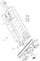
- a can bodymaker 10 is structured to convert a cup 2 ( Fig. 2 ) into a can body 3 ( Fig. 2 ).
- the cup 2 the ram body 50, the passage through the die pack 16, and other elements are assumed to have a substantially circular cross-section. It is understood, however, that the cup 2, as well as the resulting can body 3 and elements that interact with the cup 2 or can body 3, may have a shape other than substantially circular.
- a cup 2 has a bottom member 4 with a depending sidewall 5 defining a substantially enclosed space (none shown). The end of the cup bottom member 4 is open.
- the can bodymaker 10 includes a housing assembly 11, a reciprocating ram assembly 12, a drive mechanism 14, a die pack 16, a redraw assembly 18 and a cup feeder 20.
- the drive mechanism 14 includes a crank assembly 30 including a reciprocating crank arm 32.
- the cup feeder 20 positions a cup 2 in front of the die pack 16 with the open end facing the ram assembly 12.
- a redraw sleeve 40 biases the cup 2 against a redraw die 42.
- the drive mechanism 14 drives the redraw sleeve 40, e.g., via a number of secondary crank arms 36 ( Fig. 5 ), and is timed so that the redraw sleeve 40 advances just before the ram assembly 12 advances.
- the housing assembly 11 does not include a seal assembly for the ram body 50. That is, as the ram is not lubricated, the ram body 50 does not extend through a seal assembly structured to collect lubricant.
- the ram assembly 12 includes an elongated, substantially circular, ram body 50 with a proximal end 52, a distal end 54, and a longitudinal axis 56.
- the ram body distal end 54 includes a punch 58.
- the ram body proximal end 52 is coupled to the drive mechanism 14.
- the drive mechanism 14 provides a reciprocal motion to the ram body 50 causing the ram body 50 to move back and forth along its longitudinal axis 56. That is, the ram body 50 is structured to reciprocate between a retracted, first position and a forward, second position. In the first, retracted position, the ram body 50 is spaced from the die pack 16. In the second, extended position, the ram body 50 extends through the die pack 16.
- the reciprocating ram assembly 12 advances forward (to the left as shown) passing through the redraw sleeve 40 and engaging the cup 2.
- the cup 2 is moved through the redraw die 42 and a number of ironing dies (not shown) within the die pack 16.
- the cup 2 is converted into a can body 3 within the die pack 16 and then removed therefrom.
- a "cycle" means the cycle of the ram assembly 12 which begins with the ram assembly 12 in the first, retracted position.
- the can body 3 is deformed and, more specifically, the can body 3 becomes elongated while the sidewall 5 becomes thinner.
- a dome may be formed in the can bottom member 4 by known methods.
- the can body 3 is ejected from the punch 58 by any known method or device such as, but not limited to a stripper device or delivering a compressed gas to the inner side of the can body 3.
- a new cup 2 is disposed over the end of the punch 58.
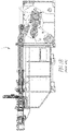
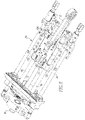
- the ram assembly 12 in an exemplary embodiment, also includes an outboard guide bearing assembly 60.
- the outboard guide bearing assembly 60 includes a carriage assembly 62 and a number of elongated journals 64.
- the first and second journals 66, 68 are slightly longer than the stroke length of the ram assembly 12 and are coupled to the bodymaker housing assembly 11.
- the carriage assembly 62 for the embodiment with two journals 66, 68, includes a generally rectangular body 70 that includes a ram coupling 72, a crank coupling 74, and which defines a number of journal passages 80.
- the ram coupling 72 is structured to support the ram body 50 in a substantially horizontal orientation.
- the crank coupling 74 in an exemplary embodiment, is a substantially circular bearing 76 that is structured to extend through a substantially circular opening (not shown) on the crank arm 32.
- the number of journal passages 80 includes a first pair of substantially aligned journal passages 82 and a second pair of substantially aligned journal passages 84.
- the journal passages 80 in each pair of journal passages 82, 84, are spaced.
- the journal passages 80 in each pair of journal passages 82, 84 are longitudinally spaced by about 8.0 to 12.0 inches, or about 10.25 inches.
- the first journal 66 extends through the first pair of substantially aligned journal passages 82, and, the second journal 68 extends through the second pair of substantially aligned journal passages 84.
- the journal passages 80 are disposed at each comer of the carriage assembly rectangular body 70.
- the bearing assembly 90 includes a carbon fiber bearing (not shown). Such a carbon fiber bearing does not require a lubricant and does not include moving elements, such as, but not limited to, ball bearings.
- the bearing assembly 90 is a "static bearing assembly.” That is, as used herein, a “static bearing assembly” is a bearing assembly that does not require a lubricant and does not include moving elements.
- the carriage assembly body 70 is structured to travel generally in a plane and to reciprocate between a retracted, first position and a forward, second position. It is understood that when the carriage assembly body 70 is in the first position, the ram body 50 is in its first position and that, when the carriage assembly body 70 is in the second position, the ram body 50 is in its second position.
- the carriage assembly body 70 has an axis of motion 78 that is substantially aligned with the ram body longitudinal axis 56. That is, the carriage assembly body axis of motion 78 may be parallel and spaced from, or be disposed substantially on, the ram body longitudinal axis 56.
- each bearing assembly 90 is a hydrostatic/hydrodynamic bearing assembly 100.
- a hydrostatic/hydrodynamic bearing assembly is either a hydrostatic bearing assembly, a hydrodynamic bearing assembly, or a combination thereof.
- a hydrostatic/hydrodynamic bearing assembly 100 includes a housing 102 and a bearing 104.
- the bearing 104 is disposed in the housing 102.
- the bearing 104 defines a passage 80 though which a journal 64 extends, as discussed above.
- the hydrostatic/hydrodynamic bearing assembly 100 i.e. the outboard guide bearing assembly 60, further includes a lubricant sump 106, a pump assembly 108 and a plurality of conduits 110, all shown schematically.
- the hydrostatic/hydrodynamic bearing assembly conduits 110 include conduits extending through the hydrostatic/hydrodynamic bearing assembly housing 102 and bearing 104.
- a lubricant such as, but not limited to oil
- bearing 104 linear motion rotation draws the fluid onto the inner surface of the bearing 104, forming a lubricating wedge or fluid lift under or around the journal 64.
- the outboard guide bearing assembly 60 does not include a seal assembly that collects the lubricant and returns the lubricant to the lubricant sump 106 or a filter assembly. Rather, a portion of the housing assembly 11, i.e., the portion below the outboard guide bearing assembly 60, is substantially hollow and defines an enclosed space that acts as the sump 106. In this configuration, lubricant from the journals 64 falls into the sump 106.
- the journals 64 are not heated to the point where a cooling fluid is required.
- the first journal 66 and second journal 68 when assembled, are horizontally aligned with, i.e. , in the same general horizontal plane, as noted above. Further, the first journal 66 and second journal 68 extend through the two pair of journal passages 82, 84.
- the carriage assembly body 70 is structured to travel in a generally horizontal plane.
- the ram body 50 is also, in an exemplary embodiment, coupled to, directly coupled to, or fixed to the carriage assembly ram coupling 72. More specifically, the ram body proximal end 52 is coupled to, directly coupled to, or fixed to the carriage assembly ram coupling 72. Further, in an exemplary embodiment, the ram body 50 is disposed in the horizontal plane defined by the first journal 66 and second journal 68.
- the carriage assembly ram coupling 72 is structured to support the ram body 50 substantially in the plane of travel.
- an outboard guide bearing assembly 60 allows the can bodymaker 10 to operate without a seal assembly disposed about the ram body 50, as noted above. Further, the ram body 50 does not pass through a hydrostatic/hydrodynamic bearing assembly 100. Thus, unlike known ram bodies that must have a sufficient length to pass through these elements/assemblies, as well as the die pack 16, the ram body 50 of the exemplary embodiment only needs to have a sufficient length to pass through the die pack 16. This reduction in the length of the ram body 50 reduces the amount of ram droop and thereby reduces the wear and tear on the ram body 50 and the die pack 16. In an exemplary embodiment, the ram body 50 has a length between about 30.0 inches and 32.0 inches, or in another embodiment, a length of about 31.0 inches. That is, the change in size ameliorates the known disadvantages of the known art.
- ram bodies 50 exist in a number of sizes. The dimensions identified above are associated with one exemplary embodiment, e.g. , a ram body 50 sized for standard 12 fluid ounce cans. In the prior art, such a ram body had a length of between about 50 inches to 52 inches when using a 24 inch stroke. Accordingly, it is understood that the disclosed concept allows for a reduction in the length of a ram body of about 40% plus or minus about an inch. Other known ram body lengths include, 45.387 inches, 50.0 inches, 51.0 inches, and 57.0 inches, all plus or minus about an inch.
- ram bodies (not shown) having lengths of about 27.0 inches, 30.0 inches, and 34.2 inches, all plus or minus about an inch.
- a ram body 50 with a reduced length has a length between about 26.0 inches and 36.0 inches, all of which are shorter than known ram body lengths. That is, as used herein, a "reduced length ram body” has a length of between about 26.0 inches and 36.0 inches.
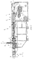
- an outboard guide bearing assembly 160 includes a carriage assembly 162 including a body 170 with a ram coupling 172, a crank coupling 174, and a number of guide bearing assemblies 180.
- the carriage assembly guide bearing assemblies 180 are separated from the ram body 50. That is, as before, the carriage assembly body 170 is, in an exemplary embodiment, generally rectangular and includes a forward, axial surface 171, a first lateral surface 173, and a second lateral surface 175.
- the ram coupling 172 is disposed on the carriage assembly body forward, axial surface 171, i.e. the forward surface through which the axis of motion passes.
- the ram coupling 172 is structured to support the ram body 50 in a substantially horizontal orientation.
- the carriage assembly body 170 is structured to travel generally in a plane and to reciprocate between a retracted, first position and a forward, second position.
- the carriage assembly guide bearing assemblies 180 include two carriage assembly guide bearing assemblies 180; a first carriage assembly guide bearing assembly 180A, and a second carriage assembly guide bearing assembly 180B.
- the first carriage assembly guide bearing assembly 180A is disposed on, and coupled to, the carriage assembly body first lateral surface 173, and, the second carriage assembly guide bearing assembly 180B is disposed on, and coupled to, the carriage assembly body second lateral surface 175. It is further understood that elements of the first and second carriage assembly guide bearing assemblies 180A, 180B are also coupled to the bodymaker housing assembly 11, as described below.
- each carriage assembly guide bearing assembly 180A, 180B includes the elements described hereinafter and such elements associated with the first carriage assembly guide bearing assembly 180A are identified by the reference letter "A” and elements associated with the second carriage assembly guide bearing assembly 180B are identified by the reference letter "B,” even when that indication is not provided with the initial description of the elements.
- a carriage assembly guide bearing assembly 180 includes a first component 182 and a second component 184.
- the carriage assembly guide bearing assembly first component 182 is a saddle 186 and the carriage assembly guide bearing assembly second component 184 is a journal channel 188.
- a journal channel 188 is a channel that defines a path of travel, similar to the journals 66, 68 described above.
- a "saddle" is a construct sized to substantially correspond to the associated channel 188. That is, the saddle has a similar, but slightly smaller, cross-sectional shape as the channel, and, a reduced longitudinal dimension. In this configuration, the saddle 186 is structured to travel through the channel 188.
- journal channel 188 is formed of a number of generally planar surfaces forming a generally square C-shaped channel. That is, the channel 188 has a generally rectangular cross-section. Accordingly, the corresponding saddle 186 has a generally rectangular cross-section as well. Further, as shown in Figure 12 , in an exemplary embodiment, saddle 186 is a generally parallelepiped construct. In an alternate embodiment, not shown, the channel 188 and the saddle 186 have a trapezoidal cross-sectional shape.
- the carriage assembly guide bearing assembly 180 is a hydrostatic/hydrodynamic bearing assembly.
- the bearing assembly first component 182 is structured to be coupled to, and in fluid communication with, a lubricant sump 106. That is, the saddle 186 includes a number of fluid ports 190 that are coupled to, and in fluid communication with, the lubricant sump 106.
- a plurality of conduits 110 provide fluid communication for a lubricant and allow the lubricant to be pumped by pump assembly 108 from the sump 106 through the fluid ports 190.
- the plurality of conduits 110 pass through the carriage assembly body 170. In this configuration, a layer of lubricant is disposed between the carriage assembly guide bearing assembly first component 182 and the carriage assembly guide bearing assembly second component 184.
- the carriage assembly guide bearing assembly second component 184 includes a gib assembly 192.
- a gib assembly 192 includes a number, typically two, generally parallel planar members (not shown) coupled by spaced, adjustable coupling components, such as but not limited to, threaded rods (not shown). The relative spacing and angle of the planar members can be adjusted by actuating the adjustable coupling components.
- a journal channel 188 is a generally square C-shaped channel having three generally planar surfaces
- each planar surface may be formed by a gib assembly 192. That is, one of each gib assembly 192 planar members forms each of the square C-shaped channel planar surface.
- the characteristics e.g. alignment of the channel surfaces or cross-sectional area of the journal channel 188, can be adjusted.
- the housing assembly 11 may, and as shown does, include a seal assembly 196 for the ram body 50. That is, as shown in Figure 16 , the seal assembly 196 includes two cup seals 197, 199, as is known. That is, one cup seal is structured to remove coolant from the ram body 50 as the ram body travels to the second position to the first position, and, the other cup seal is structured to remove lubricant from the ram body 50 as the ram body 50 travels from the first position to the second position. It is noted that the seal assembly 196 is not a bearing assembly and does not support the ram body 50 and, therefore, does not change the "cantilever length" of the ram body 50, as discussed below.
- the ram body 50 of this exemplary embodiment only needs to have a sufficient length to pass through the seal assembly 196 and the die pack 16. This reduction in the length of the ram body 50 reduces the amount of ram droop and thereby reduces the wear and tear on the ram body 50 and the die pack 16.
- the ram body 50 has a length of between about 33.0 inches to about 36.0 inches, or about 34.5 inches. That is, the change in size ameliorates the disadvantages of the known art.
- the ram body proximal end 52 is coupled to, directly coupled to, or fixed to the carriage assembly ram coupling 72 and the ram body 50 extends therefrom, the ram body 50 is a cantilever member 120, 220 ( Figures 8 and 13 ). It is noted that the assemblies, such as but not limited to an air blade 44 and a mechanical stripper 46, to the right of the redraw sleeve 40 as shown in Figure 3 does not support the ram body 50.
- a cantilever member 120 has a "cantilever length" which is the length of the cantilever member beyond the support that is closest to the unsupported end.
- the cantilever length of the prior art ram body had a dynamic cantilever length. That is, the cantilever length depended upon the length of the ram body 50 extending through the bearing assembly 60.
- the cantilever length of the cantilever member 120 remains constant during the reciprocal motion of the carriage assembly 62.
- the ram assembly 12 includes an elongated, substantially circular, generally hollow ram body 50A.
- the ram body 50A includes a proximal end 52, a distal end 54, and a longitudinal axis 56, as well as a medial portion 59.
- the inner surface of the hollow ram body 50A includes an inwardly extending flange 130.
- the ram body flange 130 is the boundary between the ram body distal end 54 and the ram body medial portion 59.
- the punch 58 is disposed on the ram body distal end 54 beyond the inwardly extending flange 130. That is, the ram body distal end 54 has a reduced radius relative to the ram body proximal end 52 and ram body medial portion 59.
- the punch 58 is generally cylindrical and includes a hollow body 57. The outer diameter of the punch body 57 is substantially the same as the outer diameter of the ram body medial portion 59 and proximal end 52.
- the punch 58 is disposed over, and coupled to, the ram body distal end 54. In this configuration, the outer transition between the punch 58 and the ram body medial portion 59 is substantially smooth.
- the ram assembly 12 also includes a tension assembly 140.
- the tension assembly 140 is structured to place the ram body 50A under tension and thereby reduce the ram droop.
- the tension assembly 140 includes an elongated support member 142, a proximal coupling assembly 144, and a distal coupling assembly 146.
- the support member 142 includes a proximal end 150, a distal end 152, and a longitudinal axis 154.
- the support member 142 is, in an exemplary embodiment, one of a rigid member or a tension member.
- the support member 142 is substantially disposed within the ram body 50A.
- the tension assembly proximal coupling assembly 144 is disposed at the ram body proximal end 52.
- the tension assembly proximal coupling assembly 144 is, in an exemplary embodiment, an adjustable coupling assembly 148. That is, in an exemplary embodiment, the support member proximal end 150 and the tension assembly proximal coupling assembly 144 are threaded couplings, e.g. a threaded rod 143 and a captive nut 145, respectively.
- the support member proximal end 150 extends through an axial passage 149 within the ram body proximal end 52.
- the ram body proximal end axial passage 149 is disposed on a collar 147 that defines an inwardly extending flange.
- the tension assembly distal coupling assembly 146 is disposed at one of the ram body medial portion 59 or ram body distal end 54. In an exemplary embodiment, the tension assembly distal coupling assembly 146 is disposed at the ram body flange 130. In an exemplary embodiment, the tension assembly distal coupling assembly 146 includes a mounting 260 and a mounting coupling assembly 262. That is, the mounting coupling assembly 262 includes the coupling components, described below, that coupled the mounting 260 to the ram body 50A.
- the tension assembly distal coupling assembly mounting 260 includes a body 264 defining an axial, first coupling assembly 266 and a radial, second coupling assembly 268.
- the tension assembly distal coupling assembly mounting body 264 is otherwise sized and shaped to fit within the ram body 50A at the ram body flange 130.
- the tension assembly distal coupling assembly mounting body first coupling assembly 266 includes, in an exemplary embodiment, a threaded cavity 270.
- the cavity 270 includes radial pins and passages therefor (not shown.)
- the tension assembly distal coupling assembly mounting body first coupling component cavity 270 corresponds to the support member distal end 152.
- the tension assembly distal coupling assembly mounting body 264 is coupled to the ram body 50A by the tension assembly distal coupling assembly mounting body second coupling assembly 268.
- the tension assembly distal coupling assembly mounting body second coupling assembly 268 includes a threaded bore 290, which extends generally radially, in the tension assembly distal coupling assembly mounting body 264.
- the tension assembly distal coupling assembly mounting body second coupling assembly 268 also includes a fastener 292 and a radial passage 294 through the ram body medial portion 59 at the flange 130.
- the tension assembly distal coupling assembly mounting body 264 is disposed within the ram body 50A at the flange 130.
- the tension assembly distal coupling assembly mounting body second coupling component fastener 292 is passed through the tension assembly distal coupling assembly mounting body second coupling component radial passage 294 and threaded into the tension assembly distal coupling assembly mounting body second coupling component threaded bore 290, thereby coupling, and fixing, the tension assembly distal coupling assembly mounting 260 to the ram body 50A.
- the support member 142 extends between, and is coupled to, the tension assembly proximal coupling assembly 144 and the tension assembly distal coupling assembly 146.
- the support member 142 is placed under tension.
- the coupling of the support member distal end 152 to the tension assembly distal coupling assembly 146 is described above.
- the support member proximal end 150 and the tension assembly proximal coupling assembly 144 are threaded couplings, e.g. a threaded rod 143 and a captive nut 145, respectively. That is, the support member proximal end 150 is threaded. In this configuration, the tension in the support member 142 can be easily adjusted.
- the captive nut 145 is threaded onto the support member proximal end 150 and drawn against the ram body proximal end collar 147.
- the captive nut 145 is drawn against the ram body proximal end collar 147 creating tension in the support member 142. Thereafter, rotating the captive nut 145 on the threaded rod 143 increases or decreases the tension on support member 142.
- the support member 142 is disposed above, and aligned with, the ram body longitudinal axis 56. That is, the support member longitudinal axis 154 is generally parallel to, and spaced from, the ram body longitudinal axis 56.
- a tension assembly 340 is structured to be substantially enclosed. That is, in this embodiment, the construct that couples the mounting body to the ram body 50A is not exposed on the ram body 50A outer surface. In this configuration, the construct that couples the mounting body 264 to the ram body 50A is not in a position that causes wear and tear on a seal assembly 196.
- the support member 142 and the tension assembly proximal coupling assembly 144 are substantially as described above. In this embodiment, however, the tension assembly distal coupling assembly 146 is as described below.
- the tension assembly distal coupling assembly 146 includes a mounting 360 and a mounting coupling assembly 362. That is, the mounting coupling assembly 362 includes the coupling components, described below, that coupled the mounting 360 to the ram body 50A.
- the tension assembly distal coupling assembly mounting 360 includes a body 364 having a first, distal end 363 and a second, proximal end 365 as well as defining the axial, first coupling assembly 366 and a radial, second coupling assembly 368.
- the tension assembly distal coupling assembly mounting body 264 is sized and shaped to fit within the ram body 50A and extend over the ram body flange 130. That is, when installed, the tension assembly distal coupling assembly mounting body distal end 363 is disposed on the distal side of the flange 130.
- the tension assembly distal coupling assembly mounting body first coupling component 266 is disposed on the tension assembly distal coupling assembly mounting body proximal end 365 and includes, in an exemplary embodiment, a threaded cavity 370.
- the tension assembly distal coupling assembly mounting body first coupling component cavity 370 corresponds to the support member distal end 252.
- the support member distal end 152 includes threads 374.
- the support member distal end 152 is threadably coupled to the tension assembly distal coupling assembly mounting body first coupling component cavity 370.
- the tension assembly distal coupling assembly mounting body 364 is coupled to the ram body 50A by the tension assembly distal coupling assembly mounting body second coupling assembly 368.
- the tension assembly distal coupling assembly mounting body second coupling assembly 368 includes a threaded bore 390, which extends generally radially, in the tension assembly distal coupling assembly mounting body 364.
- the tension assembly distal coupling assembly mounting body second coupling assembly 368 also includes a fastener 392 and a radial passage 394 through the ram body distal end 54 at a location distal to the flange 130.
- the tension assembly distal coupling assembly mounting body 364 is disposed within the ram body 50A at the flange 130.
- the tension assembly distal coupling assembly mounting body second coupling component fastener 392 is passed through the tension assembly distal coupling assembly mounting body second coupling component radial passage 394 and threaded into the tension assembly distal coupling assembly mounting body second coupling component threaded bore 390, thereby coupling, and fixing, the tension assembly distal coupling assembly mounting 260 to the ram body 50A.
- the tension assembly distal coupling assembly 146 is disposed below/within the punch 58. Stated alternately, the punch 58 covers the tension assembly distal coupling assembly 146. Thus, in operation, as the ram body reciprocates between the first and the second positions, the tension assembly distal coupling assembly 146 is not exposed and cannot contact a seal assembly 196.
- a coupling assembly that in not visible from outside the ram body 50A is a "hidden coupling.”
- the tension assembly distal coupling assembly mounting body second coupling assembly 368 is a hidden coupling.
Landscapes
- Engineering & Computer Science (AREA)
- Mechanical Engineering (AREA)
- Press Drives And Press Lines (AREA)
- Presses And Accessory Devices Thereof (AREA)
- Earth Drilling (AREA)
Claims (9)
- Machine de fabrication de corps de boîte métallique (10) comprenant un ensemble de piston (12), dans laquelle ladite machine de fabrication de corps de boîte métallique (10) comprend un mécanisme d'entraînement (14) imprimant un mouvement de va-et-vient audit ensemble de piston (12), ledit ensemble de piston (12) comprenant :un corps de piston allongé (50A), dans laquelle ledit corps de piston (50) s'étend généralement horizontalement ;ledit corps de piston (50A) comprend une extrémité proximale (52), une partie médiane (59), et une extrémité distale (54) ;un ensemble de chariot (62) ;ladite extrémité proximale de corps de piston (52) couplée audit ensemble de chariot (62), caractérisée en ce que ledit corps de piston allongé (50A) est généralement creux et moyennant quoi ledit corps de piston (50) est un élément en porte-à-faux (120) ;dans laquelle le corps de piston (50) ne s'étend pas à travers un ensemble de palier de telle sorte que la longueur de porte-à-faux dudit élément en porte-à-faux (120) reste constante pendant le mouvement de va-et-vient dudit ensemble de chariot (62) ;un ensemble de tension (140) comprenant un élément de support allongé (142) ;ledit élément de support d'ensemble de tension (142) comprenant une extrémité proximale (150) et une extrémité distale (152) ;ledit élément de support d'ensemble de tension substantiellement disposé à l'intérieur dudit corps de piston (50A) ;ladite extrémité proximale d'élément de support d'ensemble de tension (150) couplée à ladite extrémité proximale de corps de piston (52) ; etladite extrémité distale d'élément de support d'ensemble de tension (152) couplée à l'une de ladite partie médiane de corps de piston (59) ou de ladite extrémité distale de corps de piston (54).
- Machine de fabrication de corps de boîte métallique (10) selon la revendication 1, dans laquelle ledit élément de support d'ensemble de tension (142) est sous tension.
- Machine de fabrication de corps de boîte métallique (10) selon la revendication 2, dans laquelle ledit élément de support d'ensemble de tension (142) est un parmi un élément rigide ou un élément de tension.
- Machine de fabrication de corps de boîte métallique (10) selon la revendication 2, dans laquelle :ledit ensemble de tension (140) comprend un ensemble de couplage d'extrémité proximale (144) ; etdans laquelle ledit ensemble couplé à l'extrémité proximale d'ensemble de tension (144) est un ensemble de couplage ajustable (148).
- Machine de fabrication de corps de boîte métallique (10) selon la revendication 2, dans laquelle :
ledit élément de support d'ensemble de tension (142) est disposé au-dessus de, et aligné avec, l'axe longitudinal de corps de piston (56). - Machine de fabrication de corps de boîte métallique (10) selon la revendication 2, dans laquelle ledit corps de piston (50) a une longueur comprise entre environ 838 mm et 914 mm (environ 33,0 pouces et 36,0 pouces).
- Machine de fabrication de corps de boîte métallique (10) selon la revendication 6, dans laquelle ledit corps de piston (50) a une longueur d'environ 876 mm (34,5 pouces).
- Machine de fabrication de corps de boîte métallique (10) selon la revendication 1, dans laquelle :ledit ensemble de tension (140) comprend un ensemble de couplage distal (146) ;ledit ensemble de couplage distal d'ensemble de tension (146) comprend un corps de montage (264) avec un second ensemble de couplage (268) ;ledit second ensemble de couplage (268) de corps de montage d'ensemble de couplage distal d'ensemble de tension (268) comprend un alésage fileté généralement radial (290) ;ledit corps de montage d'ensemble de couplage distal d'ensemble de tension (264) disposé dans ledit corps de piston (50) avec ledit alésage fileté de second ensemble de couplage de corps de montage d'ensemble de couplage distal d'ensemble de tension (290) au niveau de ladite extrémité distale de corps de piston (54) ;un poinçon creux (58), ledit poinçon (58) couplé à ladite extrémité distale de corps de piston (54) ; etdans laquelle ledit second ensemble de couplage de corps de montage d'ensemble de couplage distal d'ensemble de tension (268) est un couplage caché.
- Machine de fabrication de corps de boîte métallique (10) selon l'une quelconque des revendications précédentes, la machine de fabrication de corps de boîte métallique (10) comprenant :
un ensemble de manivelle (30), ledit ensemble de manivelle (30) comprenant un bras de manivelle à mouvement alternatif (32).
Priority Applications (1)
| Application Number | Priority Date | Filing Date | Title |
|---|---|---|---|
| EP22175652.1A EP4066957A1 (fr) | 2013-08-28 | 2014-08-28 | Mécanisme et conception d'adressage de chute de ram |
Applications Claiming Priority (2)
| Application Number | Priority Date | Filing Date | Title |
|---|---|---|---|
| US201361870880P | 2013-08-28 | 2013-08-28 | |
| PCT/US2014/053103 WO2015031585A1 (fr) | 2013-08-28 | 2014-08-28 | Mécanisme et conception pour prévenir l'affaissement de piston |
Related Child Applications (2)
| Application Number | Title | Priority Date | Filing Date |
|---|---|---|---|
| EP22175652.1A Division EP4066957A1 (fr) | 2013-08-28 | 2014-08-28 | Mécanisme et conception d'adressage de chute de ram |
| EP22175652.1A Division-Into EP4066957A1 (fr) | 2013-08-28 | 2014-08-28 | Mécanisme et conception d'adressage de chute de ram |
Publications (3)
| Publication Number | Publication Date |
|---|---|
| EP3038768A1 EP3038768A1 (fr) | 2016-07-06 |
| EP3038768A4 EP3038768A4 (fr) | 2017-05-10 |
| EP3038768B1 true EP3038768B1 (fr) | 2022-07-20 |
Family
ID=52581276
Family Applications (2)
| Application Number | Title | Priority Date | Filing Date |
|---|---|---|---|
| EP22175652.1A Pending EP4066957A1 (fr) | 2013-08-28 | 2014-08-28 | Mécanisme et conception d'adressage de chute de ram |
| EP14839038.8A Active EP3038768B1 (fr) | 2013-08-28 | 2014-08-28 | Machine servant a faconner des corps de boites de conserve avec mécanisme et conception pour prévenir l'affaissement de piston |
Family Applications Before (1)
| Application Number | Title | Priority Date | Filing Date |
|---|---|---|---|
| EP22175652.1A Pending EP4066957A1 (fr) | 2013-08-28 | 2014-08-28 | Mécanisme et conception d'adressage de chute de ram |
Country Status (5)
| Country | Link |
|---|---|
| US (2) | US9868146B2 (fr) |
| EP (2) | EP4066957A1 (fr) |
| JP (1) | JP6305540B2 (fr) |
| CN (2) | CN107695168B (fr) |
| WO (1) | WO2015031585A1 (fr) |
Families Citing this family (10)
| Publication number | Priority date | Publication date | Assignee | Title |
|---|---|---|---|---|
| EP4066957A1 (fr) * | 2013-08-28 | 2022-10-05 | Stolle Machinery Company, LLC | Mécanisme et conception d'adressage de chute de ram |
| US10137490B2 (en) | 2013-08-28 | 2018-11-27 | Stolle Machinery Company, Llc | Outboard hydrostatic bearing assembly for can bodymaker |
| CN112371821B (zh) * | 2016-01-12 | 2023-05-05 | 斯多里机械有限责任公司 | 用于制罐机的外侧流体静力学支承组件 |
| GB2552529B (en) * | 2016-07-28 | 2019-05-15 | Crown Packaging Technology Inc | Redraw sleeve assembly |
| GB2552530B (en) * | 2016-07-28 | 2019-05-01 | Crown Packaging Technology Inc | Can bodymaker ram alignment |
| US10730093B2 (en) | 2017-04-25 | 2020-08-04 | Stolle Machinery Company, Llc | Unitary forward mounting body for a unitary forward mounting assembly |
| US10625324B2 (en) * | 2017-04-25 | 2020-04-21 | Stolle Machinery Company, Llc | Support arm—tool cradle module |
| US10792725B2 (en) | 2017-06-13 | 2020-10-06 | Stolle Machinery Company, Llc | Ram assembly with removable punch mounting assembly |
| US10589334B2 (en) * | 2018-01-03 | 2020-03-17 | Stolle Machinery Company, Llc | Dampening assembly for can bodymaker ram |
| US20220016690A1 (en) * | 2020-07-20 | 2022-01-20 | Universal Can Corporation | Can body maker and frame for drive mechanism |
Family Cites Families (25)
| Publication number | Priority date | Publication date | Assignee | Title |
|---|---|---|---|---|
| US3696657A (en) * | 1970-11-19 | 1972-10-10 | Coors Porcelain Co | Metal working crank and slide press mechanism |
| US4173138A (en) | 1977-10-28 | 1979-11-06 | Standun, Inc. | Can bodymaker having improved ram support and drive |
| ZA811240B (en) * | 1980-03-03 | 1982-03-31 | Fisher & Paykel | Methods of and/or apparatus for flanging tube ends |
| JPS602160B2 (ja) | 1981-12-21 | 1985-01-19 | 株式会社万陽 | 機械プレスの安全装置 |
| JPS58107299U (ja) * | 1982-01-13 | 1983-07-21 | 東洋製罐株式会社 | ラムの支持装置 |
| US4614104A (en) * | 1984-08-27 | 1986-09-30 | Ball Corporation | Apparatus for supporting a body for reciprocal movement |
| US4723430A (en) * | 1986-02-18 | 1988-02-09 | Adolph Coors Company | Apparatus and method for forming a surface configuration on a can body |
| JPS63164784A (ja) | 1986-12-26 | 1988-07-08 | Matsushita Electric Ind Co Ltd | ビデオカメラ |
| AU1852688A (en) * | 1987-07-01 | 1989-01-05 | Adolph Coors Company | Can body making apparatus |
| US4934167A (en) | 1987-07-01 | 1990-06-19 | Adolph Coors Company | Can body making apparatus |
| WO1990009851A1 (fr) | 1989-02-27 | 1990-09-07 | Adolph Coors Company | Appareil de fabrication de corps de boite |
| US5357779A (en) * | 1990-09-07 | 1994-10-25 | Coors Brewing Company | Can body maker with magnetic ram bearing and redraw actuator |
| US5121620A (en) * | 1991-07-19 | 1992-06-16 | Reynolds Metals Company | Retractable cupfeed for can bodymaker |
| JPH05150145A (ja) | 1991-11-28 | 1993-06-18 | Fuji Electric Co Ltd | 光フアイバへのレーザ光入射方法 |
| US5249448A (en) | 1992-07-09 | 1993-10-05 | Ball Corporation | Redraw carriage for crank and slide press |
| AU4427893A (en) | 1992-08-25 | 1994-03-03 | Ball Corporation | Apparatus for forming container bodies which utilizes a reinforced composite ram |
| US5564300A (en) * | 1993-12-28 | 1996-10-15 | Aluminum Company Of America | Ram guidance mechanism for can body maker apparatus |
| US5492000A (en) * | 1994-05-02 | 1996-02-20 | Sequa Corporation | Rotary valve controlled apparatus for stripping cans from bodymaking ram |
| US5566567A (en) * | 1995-04-25 | 1996-10-22 | Sequa Corporation | Rotary cup infeed |
| JP2005040820A (ja) * | 2003-07-28 | 2005-02-17 | Mitsubishi Materials Techno Corp | 缶の成形装置 |
| ITBO20050662A1 (it) * | 2005-10-28 | 2007-04-29 | Cevolani S P A | Unita' di alimentazione di spezzoni tubolari in lamina in macchine per la realizzazione di barattoli od assimilabili |
| DE102009016781B3 (de) * | 2009-04-07 | 2010-12-16 | Fette Gmbh | Stempel für eine Rundläuferpresse und Vorrichtung zum Montieren und Demontieren von Stempeleinsätzen für Stempel in einer Rundläuferpresse |
| JP2010287332A (ja) | 2009-06-09 | 2010-12-24 | Sumitomo Wiring Syst Ltd | 雄型端子金具およびその製造方法 |
| JP5721424B2 (ja) | 2010-12-24 | 2015-05-20 | 三菱重工業株式会社 | 横型工作機械 |
| EP4066957A1 (fr) * | 2013-08-28 | 2022-10-05 | Stolle Machinery Company, LLC | Mécanisme et conception d'adressage de chute de ram |
-
2014
- 2014-08-28 EP EP22175652.1A patent/EP4066957A1/fr active Pending
- 2014-08-28 JP JP2016537842A patent/JP6305540B2/ja active Active
- 2014-08-28 EP EP14839038.8A patent/EP3038768B1/fr active Active
- 2014-08-28 US US14/471,043 patent/US9868146B2/en active Active
- 2014-08-28 WO PCT/US2014/053103 patent/WO2015031585A1/fr active Application Filing
- 2014-08-28 CN CN201710960816.2A patent/CN107695168B/zh active Active
- 2014-08-28 CN CN201480047237.3A patent/CN105473250B/zh active Active
-
2017
- 2017-11-22 US US15/820,555 patent/US10814376B2/en active Active
Also Published As
| Publication number | Publication date |
|---|---|
| CN105473250A (zh) | 2016-04-06 |
| CN105473250B (zh) | 2018-04-17 |
| EP4066957A1 (fr) | 2022-10-05 |
| US20180071809A1 (en) | 2018-03-15 |
| US20150059429A1 (en) | 2015-03-05 |
| EP3038768A1 (fr) | 2016-07-06 |
| US9868146B2 (en) | 2018-01-16 |
| US10814376B2 (en) | 2020-10-27 |
| WO2015031585A1 (fr) | 2015-03-05 |
| CN107695168A (zh) | 2018-02-16 |
| CN107695168B (zh) | 2019-09-03 |
| JP6305540B2 (ja) | 2018-04-04 |
| JP2016534883A (ja) | 2016-11-10 |
| EP3038768A4 (fr) | 2017-05-10 |
Similar Documents
| Publication | Publication Date | Title |
|---|---|---|
| EP3038768B1 (fr) | Machine servant a faconner des corps de boites de conserve avec mécanisme et conception pour prévenir l'affaissement de piston | |
| EP3038767B1 (fr) | Machine à former les corps de boîtes métalliques avec un ensemble roulement hydrostatique extérieur | |
| US11806772B2 (en) | Outboard hydrostatic bearing assembly for can bodymaker | |
| US7114365B2 (en) | Ram guidance system | |
| JP7008115B2 (ja) | 缶ボディ製造機用のガイドベアリングアセンブリ及び缶ボディ製造機 | |
| US20080041243A1 (en) | Linear motor mounted press machine and press working method | |
| GB2141063A (en) | Redrawing-ironing apparatus | |
| EP0579119A1 (fr) | Chariot d'emboutissage de reprise pour presse à vilebrequin et glissière | |
| JP2018192510A (ja) | 缶成形装置のカップ押さえ機構、及び缶成形装置 | |
| CN220390430U (zh) | 一种液压机的液压垫结构 | |
| KR20170076054A (ko) | 하이드로포밍용 피어싱 펀치 | |
| GB1587929A (en) | Double action redraw press |
Legal Events
| Date | Code | Title | Description |
|---|---|---|---|
| PUAI | Public reference made under article 153(3) epc to a published international application that has entered the european phase |
Free format text: ORIGINAL CODE: 0009012 |
|
| 17P | Request for examination filed |
Effective date: 20160122 |
|
| AK | Designated contracting states |
Kind code of ref document: A1 Designated state(s): AL AT BE BG CH CY CZ DE DK EE ES FI FR GB GR HR HU IE IS IT LI LT LU LV MC MK MT NL NO PL PT RO RS SE SI SK SM TR |
|
| AX | Request for extension of the european patent |
Extension state: BA ME |
|
| DAX | Request for extension of the european patent (deleted) | ||
| A4 | Supplementary search report drawn up and despatched |
Effective date: 20170407 |
|
| RIC1 | Information provided on ipc code assigned before grant |
Ipc: B21D 22/30 20060101AFI20170403BHEP Ipc: B21D 22/28 20060101ALI20170403BHEP |
|
| STAA | Information on the status of an ep patent application or granted ep patent |
Free format text: STATUS: EXAMINATION IS IN PROGRESS |
|
| 17Q | First examination report despatched |
Effective date: 20191114 |
|
| STAA | Information on the status of an ep patent application or granted ep patent |
Free format text: STATUS: EXAMINATION IS IN PROGRESS |
|
| GRAP | Despatch of communication of intention to grant a patent |
Free format text: ORIGINAL CODE: EPIDOSNIGR1 |
|
| STAA | Information on the status of an ep patent application or granted ep patent |
Free format text: STATUS: GRANT OF PATENT IS INTENDED |
|
| INTG | Intention to grant announced |
Effective date: 20220215 |
|
| GRAS | Grant fee paid |
Free format text: ORIGINAL CODE: EPIDOSNIGR3 |
|
| GRAA | (expected) grant |
Free format text: ORIGINAL CODE: 0009210 |
|
| STAA | Information on the status of an ep patent application or granted ep patent |
Free format text: STATUS: THE PATENT HAS BEEN GRANTED |
|
| AK | Designated contracting states |
Kind code of ref document: B1 Designated state(s): AL AT BE BG CH CY CZ DE DK EE ES FI FR GB GR HR HU IE IS IT LI LT LU LV MC MK MT NL NO PL PT RO RS SE SI SK SM TR |
|
| REG | Reference to a national code |
Ref country code: GB Ref legal event code: FG4D |
|
| REG | Reference to a national code |
Ref country code: CH Ref legal event code: EP |
|
| REG | Reference to a national code |
Ref country code: DE Ref legal event code: R096 Ref document number: 602014084358 Country of ref document: DE |
|
| REG | Reference to a national code |
Ref country code: AT Ref legal event code: REF Ref document number: 1505204 Country of ref document: AT Kind code of ref document: T Effective date: 20220815 |
|
| REG | Reference to a national code |
Ref country code: IE Ref legal event code: FG4D |
|
| REG | Reference to a national code |
Ref country code: NL Ref legal event code: FP |
|
| REG | Reference to a national code |
Ref country code: LT Ref legal event code: MG9D |
|
| PG25 | Lapsed in a contracting state [announced via postgrant information from national office to epo] |
Ref country code: SE Free format text: LAPSE BECAUSE OF FAILURE TO SUBMIT A TRANSLATION OF THE DESCRIPTION OR TO PAY THE FEE WITHIN THE PRESCRIBED TIME-LIMIT Effective date: 20220720 Ref country code: RS Free format text: LAPSE BECAUSE OF FAILURE TO SUBMIT A TRANSLATION OF THE DESCRIPTION OR TO PAY THE FEE WITHIN THE PRESCRIBED TIME-LIMIT Effective date: 20220720 Ref country code: PT Free format text: LAPSE BECAUSE OF FAILURE TO SUBMIT A TRANSLATION OF THE DESCRIPTION OR TO PAY THE FEE WITHIN THE PRESCRIBED TIME-LIMIT Effective date: 20221121 Ref country code: NO Free format text: LAPSE BECAUSE OF FAILURE TO SUBMIT A TRANSLATION OF THE DESCRIPTION OR TO PAY THE FEE WITHIN THE PRESCRIBED TIME-LIMIT Effective date: 20221020 Ref country code: LV Free format text: LAPSE BECAUSE OF FAILURE TO SUBMIT A TRANSLATION OF THE DESCRIPTION OR TO PAY THE FEE WITHIN THE PRESCRIBED TIME-LIMIT Effective date: 20220720 Ref country code: LT Free format text: LAPSE BECAUSE OF FAILURE TO SUBMIT A TRANSLATION OF THE DESCRIPTION OR TO PAY THE FEE WITHIN THE PRESCRIBED TIME-LIMIT Effective date: 20220720 Ref country code: FI Free format text: LAPSE BECAUSE OF FAILURE TO SUBMIT A TRANSLATION OF THE DESCRIPTION OR TO PAY THE FEE WITHIN THE PRESCRIBED TIME-LIMIT Effective date: 20220720 Ref country code: ES Free format text: LAPSE BECAUSE OF FAILURE TO SUBMIT A TRANSLATION OF THE DESCRIPTION OR TO PAY THE FEE WITHIN THE PRESCRIBED TIME-LIMIT Effective date: 20220720 |
|
| REG | Reference to a national code |
Ref country code: AT Ref legal event code: MK05 Ref document number: 1505204 Country of ref document: AT Kind code of ref document: T Effective date: 20220720 |
|
| PG25 | Lapsed in a contracting state [announced via postgrant information from national office to epo] |
Ref country code: PL Free format text: LAPSE BECAUSE OF FAILURE TO SUBMIT A TRANSLATION OF THE DESCRIPTION OR TO PAY THE FEE WITHIN THE PRESCRIBED TIME-LIMIT Effective date: 20220720 Ref country code: IS Free format text: LAPSE BECAUSE OF FAILURE TO SUBMIT A TRANSLATION OF THE DESCRIPTION OR TO PAY THE FEE WITHIN THE PRESCRIBED TIME-LIMIT Effective date: 20221120 Ref country code: HR Free format text: LAPSE BECAUSE OF FAILURE TO SUBMIT A TRANSLATION OF THE DESCRIPTION OR TO PAY THE FEE WITHIN THE PRESCRIBED TIME-LIMIT Effective date: 20220720 Ref country code: GR Free format text: LAPSE BECAUSE OF FAILURE TO SUBMIT A TRANSLATION OF THE DESCRIPTION OR TO PAY THE FEE WITHIN THE PRESCRIBED TIME-LIMIT Effective date: 20221021 |
|
| REG | Reference to a national code |
Ref country code: CH Ref legal event code: PL |
|
| REG | Reference to a national code |
Ref country code: DE Ref legal event code: R097 Ref document number: 602014084358 Country of ref document: DE |
|
| PG25 | Lapsed in a contracting state [announced via postgrant information from national office to epo] |
Ref country code: SM Free format text: LAPSE BECAUSE OF FAILURE TO SUBMIT A TRANSLATION OF THE DESCRIPTION OR TO PAY THE FEE WITHIN THE PRESCRIBED TIME-LIMIT Effective date: 20220720 Ref country code: RO Free format text: LAPSE BECAUSE OF FAILURE TO SUBMIT A TRANSLATION OF THE DESCRIPTION OR TO PAY THE FEE WITHIN THE PRESCRIBED TIME-LIMIT Effective date: 20220720 Ref country code: MC Free format text: LAPSE BECAUSE OF FAILURE TO SUBMIT A TRANSLATION OF THE DESCRIPTION OR TO PAY THE FEE WITHIN THE PRESCRIBED TIME-LIMIT Effective date: 20220720 Ref country code: LU Free format text: LAPSE BECAUSE OF NON-PAYMENT OF DUE FEES Effective date: 20220828 Ref country code: LI Free format text: LAPSE BECAUSE OF NON-PAYMENT OF DUE FEES Effective date: 20220831 Ref country code: DK Free format text: LAPSE BECAUSE OF FAILURE TO SUBMIT A TRANSLATION OF THE DESCRIPTION OR TO PAY THE FEE WITHIN THE PRESCRIBED TIME-LIMIT Effective date: 20220720 Ref country code: CZ Free format text: LAPSE BECAUSE OF FAILURE TO SUBMIT A TRANSLATION OF THE DESCRIPTION OR TO PAY THE FEE WITHIN THE PRESCRIBED TIME-LIMIT Effective date: 20220720 Ref country code: CH Free format text: LAPSE BECAUSE OF NON-PAYMENT OF DUE FEES Effective date: 20220831 Ref country code: AT Free format text: LAPSE BECAUSE OF FAILURE TO SUBMIT A TRANSLATION OF THE DESCRIPTION OR TO PAY THE FEE WITHIN THE PRESCRIBED TIME-LIMIT Effective date: 20220720 |
|
| REG | Reference to a national code |
Ref country code: BE Ref legal event code: MM Effective date: 20220831 |
|
| PLBE | No opposition filed within time limit |
Free format text: ORIGINAL CODE: 0009261 |
|
| STAA | Information on the status of an ep patent application or granted ep patent |
Free format text: STATUS: NO OPPOSITION FILED WITHIN TIME LIMIT |
|
| PG25 | Lapsed in a contracting state [announced via postgrant information from national office to epo] |
Ref country code: SK Free format text: LAPSE BECAUSE OF FAILURE TO SUBMIT A TRANSLATION OF THE DESCRIPTION OR TO PAY THE FEE WITHIN THE PRESCRIBED TIME-LIMIT Effective date: 20220720 Ref country code: EE Free format text: LAPSE BECAUSE OF FAILURE TO SUBMIT A TRANSLATION OF THE DESCRIPTION OR TO PAY THE FEE WITHIN THE PRESCRIBED TIME-LIMIT Effective date: 20220720 |
|
| P01 | Opt-out of the competence of the unified patent court (upc) registered |
Effective date: 20230429 |
|
| 26N | No opposition filed |
Effective date: 20230421 |
|
| PG25 | Lapsed in a contracting state [announced via postgrant information from national office to epo] |
Ref country code: AL Free format text: LAPSE BECAUSE OF FAILURE TO SUBMIT A TRANSLATION OF THE DESCRIPTION OR TO PAY THE FEE WITHIN THE PRESCRIBED TIME-LIMIT Effective date: 20220720 |
|
| PG25 | Lapsed in a contracting state [announced via postgrant information from national office to epo] |
Ref country code: IE Free format text: LAPSE BECAUSE OF NON-PAYMENT OF DUE FEES Effective date: 20220828 Ref country code: FR Free format text: LAPSE BECAUSE OF NON-PAYMENT OF DUE FEES Effective date: 20220920 |
|
| PG25 | Lapsed in a contracting state [announced via postgrant information from national office to epo] |
Ref country code: SI Free format text: LAPSE BECAUSE OF FAILURE TO SUBMIT A TRANSLATION OF THE DESCRIPTION OR TO PAY THE FEE WITHIN THE PRESCRIBED TIME-LIMIT Effective date: 20220720 |
|
| PGFP | Annual fee paid to national office [announced via postgrant information from national office to epo] |
Ref country code: NL Payment date: 20230719 Year of fee payment: 10 |
|
| PG25 | Lapsed in a contracting state [announced via postgrant information from national office to epo] |
Ref country code: BE Free format text: LAPSE BECAUSE OF NON-PAYMENT OF DUE FEES Effective date: 20220831 |
|
| PGFP | Annual fee paid to national office [announced via postgrant information from national office to epo] |
Ref country code: GB Payment date: 20230706 Year of fee payment: 10 |
|
| PGFP | Annual fee paid to national office [announced via postgrant information from national office to epo] |
Ref country code: DE Payment date: 20230703 Year of fee payment: 10 |
|
| PG25 | Lapsed in a contracting state [announced via postgrant information from national office to epo] |
Ref country code: HU Free format text: LAPSE BECAUSE OF FAILURE TO SUBMIT A TRANSLATION OF THE DESCRIPTION OR TO PAY THE FEE WITHIN THE PRESCRIBED TIME-LIMIT; INVALID AB INITIO Effective date: 20140828 |
|
| PG25 | Lapsed in a contracting state [announced via postgrant information from national office to epo] |
Ref country code: CY Free format text: LAPSE BECAUSE OF FAILURE TO SUBMIT A TRANSLATION OF THE DESCRIPTION OR TO PAY THE FEE WITHIN THE PRESCRIBED TIME-LIMIT Effective date: 20220720 |