EP3037336B1 - Ensemble de pignons pour bicyclette - Google Patents
Ensemble de pignons pour bicyclette Download PDFInfo
- Publication number
- EP3037336B1 EP3037336B1 EP15196198.4A EP15196198A EP3037336B1 EP 3037336 B1 EP3037336 B1 EP 3037336B1 EP 15196198 A EP15196198 A EP 15196198A EP 3037336 B1 EP3037336 B1 EP 3037336B1
- Authority
- EP
- European Patent Office
- Prior art keywords
- sprocket
- last
- diameter
- spacer
- sprockets
- Prior art date
- Legal status (The legal status is an assumption and is not a legal conclusion. Google has not performed a legal analysis and makes no representation as to the accuracy of the status listed.)
- Active
Links
- 125000006850 spacer group Chemical group 0.000 claims description 70
- 230000003247 decreasing effect Effects 0.000 claims description 4
- 241000723353 Chrysanthemum Species 0.000 description 2
- 235000005633 Chrysanthemum balsamita Nutrition 0.000 description 2
- 230000033001 locomotion Effects 0.000 description 2
- 239000000463 material Substances 0.000 description 2
- 210000003205 muscle Anatomy 0.000 description 2
- 208000036829 Device dislocation Diseases 0.000 description 1
- 229910000831 Steel Inorganic materials 0.000 description 1
- RTAQQCXQSZGOHL-UHFFFAOYSA-N Titanium Chemical compound [Ti] RTAQQCXQSZGOHL-UHFFFAOYSA-N 0.000 description 1
- 239000004411 aluminium Substances 0.000 description 1
- XAGFODPZIPBFFR-UHFFFAOYSA-N aluminium Chemical compound [Al] XAGFODPZIPBFFR-UHFFFAOYSA-N 0.000 description 1
- 229910052782 aluminium Inorganic materials 0.000 description 1
- 230000000712 assembly Effects 0.000 description 1
- 238000000429 assembly Methods 0.000 description 1
- 230000005540 biological transmission Effects 0.000 description 1
- 230000001351 cycling effect Effects 0.000 description 1
- 238000003780 insertion Methods 0.000 description 1
- 230000037431 insertion Effects 0.000 description 1
- 238000012986 modification Methods 0.000 description 1
- 230000004048 modification Effects 0.000 description 1
- 239000010959 steel Substances 0.000 description 1
- 239000010936 titanium Substances 0.000 description 1
- 229910052719 titanium Inorganic materials 0.000 description 1
Images


Classifications
-
- B—PERFORMING OPERATIONS; TRANSPORTING
- B62—LAND VEHICLES FOR TRAVELLING OTHERWISE THAN ON RAILS
- B62M—RIDER PROPULSION OF WHEELED VEHICLES OR SLEDGES; POWERED PROPULSION OF SLEDGES OR SINGLE-TRACK CYCLES; TRANSMISSIONS SPECIALLY ADAPTED FOR SUCH VEHICLES
- B62M9/00—Transmissions characterised by use of an endless chain, belt, or the like
- B62M9/04—Transmissions characterised by use of an endless chain, belt, or the like of changeable ratio
- B62M9/06—Transmissions characterised by use of an endless chain, belt, or the like of changeable ratio using a single chain, belt, or the like
- B62M9/10—Transmissions characterised by use of an endless chain, belt, or the like of changeable ratio using a single chain, belt, or the like involving different-sized wheels, e.g. rear sprocket chain wheels selectively engaged by the chain, belt, or the like
- B62M9/12—Transmissions characterised by use of an endless chain, belt, or the like of changeable ratio using a single chain, belt, or the like involving different-sized wheels, e.g. rear sprocket chain wheels selectively engaged by the chain, belt, or the like the chain, belt, or the like being laterally shiftable, e.g. using a rear derailleur
Definitions
- the present invention relates to a sprocket assembly for a bicycle, in particular for a racing bicycle.
- the bicycle is a mechanical device moved by muscle power, hence one of the main requirements to be satisfied in the field of bicycles, particularly racing bicycles, is to allow the best possible exploitation of such a muscle power.
- a conventional motion transmission system comprises, in the rear part of the bicycle, a hub associated with the rear wheel of the bicycle and provided with a body, in the jargon known as “freewheel body”, capable of rotating idly with respect to the hub in one direction of rotation and of pushing the hub into rotation in the opposite direction.
- the freewheel body is in general a cylindrical body having, on the radially outer surface thereof, a plurality of longitudinal grooves configured to engage the sprockets of decreasing diameter of a sprocket assembly.
- the sprockets in turn are engaged with, and pushed in rotation by, a chain which receives the movement from at least one toothed front sprocket associated with one of the two crank arms coupled with the shaft of the bottom bracket assembly of the bicycle.
- the sprockets are generally made of an extremely strong material (like steel or titanium) to withstand the wearing generated by the sliding of the chain and the loads which they are subjected to during operation.
- the sprockets can comprise a radially inner surface provided with grooves configured to engage the grooves of the freewheel body.
- the sprockets can be supported by support elements, often made from light material (like aluminium), having a radially inner surface provided with grooves configured to engage the grooves of the freewheel body.
- a support element can also support more than one sprocket.
- each spacer is arranged between two adjacent sprockets or between two adjacent support elements, if provided.
- the support elements support two sprockets arranged on opposite sides, they also act as spacers.
- the spacers can comprise a radially inner surface provided with groves configured to engage the grooves of the freewheel body.
- sprocket assemblies In the field of racing bicycles, sprocket assemblies are known having nine, ten or even eleven sprockets.
- the sprocket having the smallest diameter of the sprocket assembly has a radially outer toothing (configured to engage the chain) with, typically, eleven or twelve teeth.
- the Applicant has felt the need to add, to a sprocket assembly of the type described above, an additional sprocket having a smaller number of teeth with respect to the number of teeth of the sprocket having the smallest diameter of the sprocket assembly, so as to provide the cyclist with a further gear ratio characterised by being extremely long, thus very suitable for flat terrain, downhill and also for sprint finishes in cycling competitions.
- the aforementioned additional sprocket is also indicated as “last sprocket”, whereas the aforementioned sprocket having a smaller diameter is also indicated as “second-last sprocket”.
- an additional sprocket in a sprocket assembly requires the provision of an additional spacer arranged between such a sprocket and the sprocket having a larger diameter which is immediately adjacent thereto, such a spacer being configured to be fitted onto a free end portion of the freewheel body.
- the additional spacer in order to ensure that the additional spacer has a sufficient structural strength, since the inner diameter of the additional spacer is imposed by the outer radial size of the freewheel body, the additional spacer should have an outer diameter that in certain cases can be greater than the diameter defined in the additional sprocket at the bottom of the throats of the toothing.
- the present invention therefore, in a first aspect thereof, relates to a bicycle sprocket assembly according to claim 1.
- the present invention relates to a bicycle sprocket assembly comprising:
- the provision of the aforementioned recessed areas on the radially outer surface of the additional spacer (last spacer) allows the correct meshing of the chain on the teeth of the additional sprocket (last sprocket) in the case in which the outer radial size of the additional spacer (last spacer) is greater than that of the bottom surfaces of the throats of the teeth of the additional sprocket (last sprocket).
- the sprocket assembly of the present invention can comprise one or more of the following preferred features, taken individually or in combination.
- the last sprocket (additional sprocket) has ten teeth and the second-last sprocket has eleven or twelve teeth.
- the last sprocket (additional sprocket) is configured to be mounted canti-levered with respect to said freewheel body.
- the canti-levered mounting of the last sprocket (additional sprocket) with respect to the freewheel body makes it possible to use the sprocket assembly provided with the aforementioned last sprocket (additional sprocket) with freewheel bodies having conventional shape and size, without the need to carry out any mechanical processing on such freewheel bodies.
- the freewheel body has a radially outer surface comprising a plurality of longitudinal grooves defining a plurality of projections and a plurality of recesses, each recess being arranged between two consecutive projections, wherein said projections comprise respective head surfaces that belong to a third circumference having a fourth diameter greater than said first diameter.
- the last spacer (additional spacer) is made in a single piece with the last sprocket (additional sprocket) and the second-last sprocket.
- the last sprocket (additional sprocket), the last spacer (additional spacer) and the second-last sprocket are made in a single piece with a third-last sprocket of said plurality of sprockets.
- the last sprocket (additional sprocket), the last spacer (additional spacer) and the second-last sprocket can be made in distinct pieces and can be coupled together so as to form a preassembled module configured to later be coupled with the freewheel body.
- the sprocket assembly of the invention comprises a second-last spacer arranged between the second-last sprocket and the third-last sprocket, said second-last spacer comprising a radially outer surface having a fifth diameter greater than said second diameter.
- the radially inner surface of the last spacer is a cylindrical surface with a circular section.
- the second-last sprocket comprises a radially inner surface having a shape matching the radially outer surface of said freewheel body.
- a radially inner surface comprises longitudinal grooves configured to engage the grooves provided on the radially outer surface of the freewheel body.
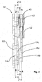
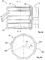
- a bicycle sprocket assembly in accordance with the present invention is shown.
- the sprocket assembly is wholly indicated with 10.
- the sprocket assembly 10 is mounted on a freewheel body 20 of a hub for a rear bicycle wheel.
- the hub comprises a hub body 15 and a freewheel body 20.
- the freewheel body 20 is coupled with the hub body 15 through any known system (not shown) through which the freewheel body 20 can rotate idly in one direction of rotation about a rotation axis X-X and push the hub body 15 in the opposite direction of rotation.
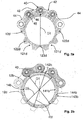
- Figures 3a, 3b and figures 6a, 6b respectively show two different types of freewheel bodies 20 of the conventional type available on the market, which differ in that they have different shapes and sizes.
- the freewheel body 20 has a substantially cylindrical shape and has, on the radially outer surface 21 thereof, a plurality of longitudinal grooves 22 configured to be coupled with the sprocket assembly 10 to allow the rotation as a single unit of the sprocket assembly 10 and of the freewheel body 20 about the rotation axis X-X.
- the longitudinal grooves 22 define, on the radially outer surface 21 of the freewheel body 20, projections 24 and recesses 26.
- the projections 24 comprise respective head surfaces 24a that belong to an ideal circumference having its centre on the rotation axis X-X and a diameter D4 for example equal to about 35 mm in the type of freewheel body 20 shown in figures 3a and 3b and equal to about 34.4 mm in the type of freewheel body 20 shown in figures 6a and 6b .
- the recesses 26 comprise respective base surfaces 26a that belong to an ideal circumference having its centre on the rotation axis X-X and a diameter D6 for example equal to about 29 mm in the type of freewheel body 20 shown in figures 3a and 3b and equal to about 32.1 mm in the type of freewheel body 20 shown in figures 6a and 6b .
- the sprocket assembly. 10 comprises a plurality of sprockets 12 having decreasing diameter (reference numeral 12 is associated with just some of the sprockets shown).
- Reference numeral 12a indicates the sprocket having the largest diameter and reference numerals 12b, 12c, 12d indicate the three sprockets having smaller diameter of the sprocket assembly 10, wherein sprocket 12c has a smaller diameter than that of sprocket 12b and greater than that of sprocket 12d.
- Sprocket 12d is the one which in the introductory part of this description and in the subsequent claims is also indicated as “additional sprocket” or “last sprocket”, whereas sprocket 12c is the one which in the introductory part of this description and in the subsequent claims is also indicated as “second-last sprocket” and sprocket 12b is the one which in the introductory part of this description and in the subsequent claims is also indicated as "third-last sprocket”.
- the sprocket assembly 10 comprises eleven sprockets in total.
- Sprocket 12a is mounted on the freewheel body 20 and abuts against an axial abutment element 28 of the freewheel body 20.
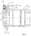
- Sprocket 12d is mounted canti-levered with respect to the freewheel body 20, as shown in figures 4a , 4b and 7a , 7b .
- the sprocket assembly 10 further comprises a plurality of spacers 14, each arranged between two consecutive sprockets 12 (reference numeral 14 is associated with just some of the spacers shown).
- Reference numeral 14a indicates the spacer arranged between sprockets 12b and 12c, whereas reference numeral 14b indicates the spacer arranged between sprockets 12b and 12c.
- Spacer 14a is the one which in the introductory part of this description and in the subsequent claims is also indicated as “second-last spacer”
- spacer 14b is the one which in the introductory part of this description and in the subsequent claims is also indicated as “last spacer”.
- Spacer 14a is mounted on the freewheel body 20 at the projections 24, whereas spacer 14b is mounted on the freewheel body 20 at a free end portion 23 thereof whose radially outer surface has no grooves 22.
- the attached figures show a conventional chain 40 engaged on the sprocket 12d.
- the chain 40 comprises a succession of links 42, each link consisting of a pair of plates 44 facing one another and spaced apart to define an insertion space for a tooth of the sprocket 12d.
- the plates 44 of a link 42 are coupled with the plates 44 of the subsequent link 42 through a rivet 46, which in turn is surrounded by a bush 48 capable of rotating freely with respect to the rivet 46.
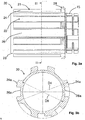
- FIG. 2 shows a part of the sprocket assembly 10.
- a sprocket module is shown comprising the three sprockets of smallest diameter 12b, 12c and 12d of the sprocket assembly 10 and the spacers 14a and 14b.
- Such a module is wholly indicated with 30.
- the module 30 comprises a sprocket 12d having ten teeth, a sprocket 12c having eleven teeth and a sprocket 12b having twelve teeth.
- FIGS 4a , 4b and figures 7a , 7b respectively illustrate two different embodiments of the module 30, which differ in that they have different shapes and sizes.
- Sprockets 12b, 12c and 12d and spacers 14a and 14b are made in a single piece.
- sprockets 12b, 12c and 12d and spacers 14a and 14b are made in a single piece.
- sprockets 12b, 12c and 12d and spacers 14a and 14b are made in distinct pieces and are coupled together so as to form a preassembled module.
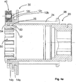
- Figure 4a shows a first embodiment of the sprocket module 30 of figure 2 mounted on the freewheel body 20 of figures 3a, 3b
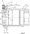
- figure 7a shows a second embodiment of the sprocket module 30 of figure 2 mounted on the freewheel body 20 of figures 6a, 6b .
- the sprocket module 30 of figure 7a differs from the sprocket module 30 of figure 4a in that it has, being equal the outer radial dimensions of sprockets 12b, 12c, 12d and spacers 14a, 14b and being equal the number of teeth of each of the sprockets 12b, 12c, 12d, larger inner radial dimensions.
- a locking ring nut 50 is screwed onto the freewheel body 20.
- the locking ring nut 50 comprises a substantially cylindrical portion 52 and a substantially annular portion 54 that projects radially outwards with respect to the substantially cylindrical portion 52.
- the substantially cylindrical portion 52 is provided with an outer threading 53 that is screwed onto an inner threading 25 of the freewheel body 20.
- the substantially annular portion 54 abuts axially on the sprocket 12d, locking the sprocket assembly 10 on the freewheel body 20.
- Figures 4b and 7b show a variant of the sprocket module 30 and of the locking ring nut 50 respectively of figures 4a and 7a .
- the sprocket module 30 of figures 4b , 7b differs from that of figures 4a , 7a solely in that a bevel or flaring 32 is provided on a radially inner surface of the sprocket 12d.
- the locking ring nut 50 of figures 4b , 7b differs from that of figures 4a , 7a solely in that a radiused surface 56 is provided between the substantially cylindrical portion 52 and the substantially annular portion 54.
- the sprocket 12d has a plurality of throats 121 d, each arranged between two consecutive teeth 122d.
- the throats 121d comprise respective bottom surfaces 123d substantially tangent to a circumference having a diameter D1.
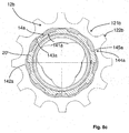
- FIGS. 5a and 8a it is possible to see the spacer 14b arranged between the sprockets 14d and 14c of the two modules 30 respectively of figures 4a , 4b and 7a , 7b .
- Such a spacer 14b in both cases has a substantially annular shape and a radially inner surface 141 b that is associated with a free end portion 23 of the freewheel body 20 of figures 3a, 3b and 6a, 6b .
- Such a radially inner surface 141b is a cylindrical surface with a circular section having a diameter D7,
- the spacer 14b comprises a radially outer surface 142b having a diameter D2 greater than the diameter D1.
- the spacer 14b comprises a plurality of recessed areas 143b. Each recessed area 143b is positioned at a respective throat 121d of the sprocket 12d.
- the recessed areas 143b provide the radially outer surface 142b of the spacer 14b with a shape that vaguely resembles the profile of a daisy.
- the recessed areas 143b comprise respective base surfaces 144b substantially tangent to a circumference having a diameter D3 substantially equal to the diameter D1.
- the sprocket 12c has a plurality of throats 123c, each arranged between two consecutive teeth 124c.
- the throats 123c comprise respective bottom surfaces 125c substantially tangent to a circumference having a diameter D8.
- the sprocket 12c comprises a radially inner surface 121c having a shape matching the radially outer surface 21 of the freewheel body 20.
- the radially inner surface 121c comprises longitudinal grooves 122c configured to engage the grooves 22 provided on the radially outer surface 21 of the freewheel body 20.
- the sprocket 12b has a plurality of throats 121 b, each arranged between two consecutive teeth 122b.
- the sprocket 12b comprises a radially inner surface (not visible in figures 5c , 8c ) of a shape matching the radially outer surface 21 of the freewheel body 20, and thus provided with longitudinal grooves configured to engage the grooves 22 provided on the radially outer surface 21 of the freewheel body 20.
- the spacer 14a arranged between the sprocket 12c and the sprocket 12b comprises a radially outer surface 142a having a radial size greater than that of the radially outer surface 142b of the spacer 14b.
- the radially outer surface 142a has a diameter D5 greater than the diameter D2.
- the spacer 14a comprises a radially inner surface 141 a having a shape matching the radially outer surface 21 of the freewheel body 20.
- the radially inner surface 141a comprises longitudinal grooves 143a configured to engage the grooves 22 provided on the radially outer surface 21 of the freewheel body 20.
- the spacer 14a comprises a plurality of recessed areas 144a. Each recessed area 144a is positioned at a respective throat 123c of the sprocket 12c.
- the recessed areas 144a also in this case provide the radially outer surface del spacer 14a with a shape that vaguely resembles the profile of a daisy.
- the recessed areas 144a comprise respective base surfaces 145a substantially tangent to a circumference having a diameter D9 substantially equal to the diameter D8.
- the spacer 14a has a radially outer surface without recessed areas.
- the outer radial size of the spacer 14a is smaller than or equal to the diameter D8.
- the spacer 14a is defined by a plurality of spacer elements made in one piece with, and axially projecting canti-levered from, at least one of the sprockets 12b and 12c (preferably, made in one piece with both the sprockets 12b, 12c), such spacer elements being arranged at the projections of the longitudinal grooves 122c of the radially inner surface 121c of the sprocket 12c (in the case in which the spacer elements are made in one piece with the sprocket 12c) or at the projections of the longitudinal grooves of the radially inner surface of the sprocket 12b (in the case in which the.spacer elements are made in one piece with the sprocket 12b).
Landscapes
- Engineering & Computer Science (AREA)
- Chemical & Material Sciences (AREA)
- Combustion & Propulsion (AREA)
- Transportation (AREA)
- Mechanical Engineering (AREA)
- Gears, Cams (AREA)
Claims (9)
- Ensemble de pignons pour bicyclette (10), comprenant :- une pluralité de pignons (12) de diamètre décroissant configurés pour être montés sur un corps de roue libre (20) d'un moyeu de bicyclette, ladite pluralité de pignons (12) incluant un premier pignon de plus grand diamètre (12a) et un dernier pignon de plus petit diamètre (12d), où ledit dernier pignon (12d) comprend une pluralité de dents (122d) et une pluralité de gorges (121d), chaque gorge (121d) étant agencée entre deux dents (122d) consécutives, lesdites gorges (121d) comprenant des surfaces de fond respectives (123d) sensiblement tangentes à une première circonférence présentant une premier diamètre (D1) ;- une pluralité d'éléments d'espacement (14) agencés entre ledit premier pignon (12a) et ledit dernier pignon (12d), ladite pluralité d'éléments d'espacement (14) incluant un dernier élément d'espacement (14b) agencé entre ledit dernier pignon (12d) et un avant-dernier pignon (12c) de ladite pluralité de pignons (12) et présentant une surface radialement intérieure (141b) configurée pour être installée sur une partie d'extrémité libre (23) dudit corps de roue libre (20) ;caractérisé en ce que ledit dernier élément d'espacement (14b) comprend une surface radialement extérieure (142b) présentant un deuxième diamètre (D2) supérieur audit premier diamètre (D1) et incluant une pluralité de zones évidées (143b), chaque zone évidée (143b) étant positionnée au niveau d'une gorge respective parmi ladite pluralité de gorges (121d), où lesdites zones évidées (143b) comprennent des surfaces de base respectives (144b) sensiblement tangentes à une deuxième circonférence présentant un troisième diamètre (D3) inférieur ou égal audit premier diamètre (D1).
- Ensemble de pignons (10) selon la revendication 1, dans lequel ledit dernier pignon (12d) comporte dix dents et ledit avant-dernier pignon (12c) comporte onze ou douze dents.
- Ensemble de pignons (10) selon la revendication 1 ou 2, dans lequel ledit dernier pignon (12d) est configuré pour être monté en porte-à-faux par rapport audit corps de roue libre (20).
- Ensemble de pignons (10) selon l'une quelconque des revendications précédentes, dans lequel ledit corps de roue libre (20) présente une surface radialement extérieure (21) comprenant une pluralité de rainures longitudinales (22) définissant une pluralité de protubérances (24) et une pluralité d'évidements (26), chaque évidement (26) étant agencé entre deux protubérances (24) consécutives, où lesdites protubérances (24) comprennent des surfaces de tête respectives (24a) qui appartiennent à une troisième circonférence présentant un quatrième diamètre (D4) supérieur audit premier diamètre (D1).
- Ensemble de pignons (10) selon l'une quelconque des revendications précédentes, dans lequel ledit dernier élément d'espacement (14b) est fabriqué en un seul tenant avec ledit dernier pignon (12d) et ledit avant-dernier pignon (12c).
- Ensemble de pignons (10) selon la revendication 5, dans lequel ledit dernier pignon (12d), ledit dernier élément d'espacement (14b) et ledit avant-dernier pignon (12c) sont fabriqués en un seul tenant avec un avant-avant-dernier pignon (12b) de ladite pluralité de pignons (12).
- Ensemble de pignons (10) selon la revendication 6, comprenant un avant-dernier élément d'espacement (14a) agencé entre ledit avant-dernier pignon (12c) et ledit avant-avant-dernier pignon (12b), où ledit avant-dernier élément d'espacement (14a) comprend une surface radialement extérieure (142a) présentant un cinquième diamètre (D5) supérieur audit deuxième diamètre (D2).
- Ensemble de pignons (10) selon l'une quelconque des revendications précédentes, dans lequel ladite surface radialement intérieure (141b) est une surface cylindrique ayant une section circulaire.
- Ensemble de pignons (10) selon l'une quelconque des revendications précédentes, dans lequel ledit avant-dernier pignon (12c) comprend une surface radialement intérieure (121c) ayant une forme correspondant à la surface radialement extérieure (21) dudit corps de roue libre (20).
Applications Claiming Priority (1)
| Application Number | Priority Date | Filing Date | Title |
|---|---|---|---|
| ITMI20142224 | 2014-12-23 |
Publications (2)
| Publication Number | Publication Date |
|---|---|
| EP3037336A1 EP3037336A1 (fr) | 2016-06-29 |
| EP3037336B1 true EP3037336B1 (fr) | 2017-04-12 |
Family
ID=52355044
Family Applications (1)
| Application Number | Title | Priority Date | Filing Date |
|---|---|---|---|
| EP15196198.4A Active EP3037336B1 (fr) | 2014-12-23 | 2015-11-25 | Ensemble de pignons pour bicyclette |
Country Status (5)
| Country | Link |
|---|---|
| US (1) | US9580144B2 (fr) |
| EP (1) | EP3037336B1 (fr) |
| JP (1) | JP6463665B2 (fr) |
| CN (1) | CN105966543B (fr) |
| TW (1) | TWI678317B (fr) |
Cited By (1)
| Publication number | Priority date | Publication date | Assignee | Title |
|---|---|---|---|---|
| IT202200001736A1 (it) | 2022-02-02 | 2023-08-02 | Giuseppe Malavolta | Cambio e sistema di trasmissione di veicolo a propulsione umana o mista e bicicletta |
Families Citing this family (24)
| Publication number | Priority date | Publication date | Assignee | Title |
|---|---|---|---|---|
| US8820192B2 (en) | 2009-04-29 | 2014-09-02 | Race Face Prerformance Products Inc. | Bicycle crank arm and insert therefore |
| CA2964058A1 (fr) | 2016-04-11 | 2017-10-11 | Fox Factory, Inc. | Pignon avant de bicyclette |
| US11014628B2 (en) | 2017-04-28 | 2021-05-25 | Fox Factory, Inc. | Cinch direct mount 2X ring system |
| CN108974233B (zh) * | 2017-05-30 | 2021-01-05 | 株式会社岛野 | 自行车后链轮组件和自行车传动系 |
| US10946931B2 (en) | 2017-09-22 | 2021-03-16 | Shimano Inc. | Bicycle rear sprocket assembly and bicycle drive train |
| US11179967B2 (en) | 2017-05-30 | 2021-11-23 | Shimano Inc. | Bicycle hub assembly |
| TWI839049B (zh) * | 2017-05-30 | 2024-04-11 | 日商島野股份有限公司 | 自行車輪轂總成 |
| US10377174B2 (en) | 2017-08-09 | 2019-08-13 | Shimano Inc. | Bicycle hub assembly |
| US11059541B2 (en) | 2017-05-30 | 2021-07-13 | Shimano Inc. | Bicycle hub assembly |
| TWI707801B (zh) * | 2017-05-30 | 2020-10-21 | 日商島野股份有限公司 | 自行車後鏈輪總成 |
| DE202018006055U1 (de) * | 2017-05-30 | 2019-01-28 | Shimano Inc. | Hintere Fahrradkettenradanordnung und Fahrradantriebsstrang |
| US11332213B2 (en) | 2017-05-30 | 2022-05-17 | Shimano Inc. | Bicycle rear sprocket assembly and bicycle drive train |
| US11220309B2 (en) | 2017-05-30 | 2022-01-11 | Shimano Inc. | Bicycle rear sprocket assembly |
| US10752320B2 (en) | 2017-09-22 | 2020-08-25 | Shimano Inc. | Bicycle rear hub assembly |
| CN111542471A (zh) * | 2017-08-21 | 2020-08-14 | 劲锋铁马股份有限公司 | 具有夹紧连接的自行车塔轮 |
| US11072203B2 (en) * | 2018-08-22 | 2021-07-27 | Sram, Llc | Bicycle sprocket assembly |
| US11359709B2 (en) * | 2018-12-18 | 2022-06-14 | Fox Factory, Inc. | Chainring |
| US11680633B2 (en) | 2019-02-08 | 2023-06-20 | Fox Factory, Inc. | Chainring |
| TWI839545B (zh) * | 2019-07-30 | 2024-04-21 | 義大利商坎帕克諾羅公司 | 用於自行車後輪的變速盤和子組件 |
| IT201900013287A1 (it) * | 2019-07-30 | 2021-01-30 | Campagnolo Srl | Adattatore per un corpo porta-pignoni per una ruota posteriore di bicicletta |
| EP3960606A1 (fr) * | 2020-09-01 | 2022-03-02 | SRAM Deutschland GmbH | Module à pignons multiples et module de roue arrière pour une bicyclette à dérailleur |
| US11858588B2 (en) * | 2021-04-29 | 2024-01-02 | Shimano Inc. | Rear sprocket assembly and lock device |
| US11603166B2 (en) * | 2021-04-29 | 2023-03-14 | Shimano Inc. | Rear sprocket assembly and lock device |
| US11767080B1 (en) * | 2022-07-15 | 2023-09-26 | Shimano Inc. | Rear sprocket assembly |
Family Cites Families (11)
| Publication number | Priority date | Publication date | Assignee | Title |
|---|---|---|---|---|
| JPS5885587U (ja) * | 1981-12-08 | 1983-06-10 | 株式会社シマノ | 自転車用多段スプロケツト装置 |
| JP3562883B2 (ja) * | 1995-09-29 | 2004-09-08 | 株式会社シマノ | 自転車後輪用多段ホイール |
| US6866604B2 (en) * | 2003-01-17 | 2005-03-15 | Shimano, Inc. | Multiple level sprocket support for a bicycle |
| JP2007113711A (ja) * | 2005-10-21 | 2007-05-10 | Shimano Inc | 自転車用フリーホイール |
| US20080004143A1 (en) * | 2006-06-16 | 2008-01-03 | Shimano Inc. | Bicycle sprocket assembly |
| US7753815B2 (en) * | 2007-01-19 | 2010-07-13 | Shimano Components (Malaysia) Sdn. Bhd. | Bicycle chain wheel assembly |
| ITMI20071659A1 (it) * | 2007-08-09 | 2009-02-10 | Campagnolo Srl | Assieme di pignoni per una ruota posteriore di bicicletta e pacco pignoni comprendente tale assieme |
| TWM399087U (en) * | 2010-08-25 | 2011-03-01 | Orbit Design Co Ltd | Hub sleeve for fly wheels in varied specifications |
| US8641151B2 (en) * | 2010-11-12 | 2014-02-04 | Shimano Inc. | Sprocket support structure |
| TWM409185U (en) * | 2011-01-26 | 2011-08-11 | Orbit Design Co Ltd | Hub sleeve for fly wheels in varied specifications |
| US8696503B2 (en) * | 2011-03-01 | 2014-04-15 | Shimano Inc. | Bicycle sprocket assembly |
-
2015
- 2015-11-25 EP EP15196198.4A patent/EP3037336B1/fr active Active
- 2015-11-30 TW TW104139961A patent/TWI678317B/zh active
- 2015-12-09 JP JP2015239879A patent/JP6463665B2/ja active Active
- 2015-12-23 CN CN201510977438.XA patent/CN105966543B/zh active Active
- 2015-12-23 US US14/757,940 patent/US9580144B2/en active Active
Non-Patent Citations (1)
| Title |
|---|
| None * |
Cited By (2)
| Publication number | Priority date | Publication date | Assignee | Title |
|---|---|---|---|---|
| IT202200001736A1 (it) | 2022-02-02 | 2023-08-02 | Giuseppe Malavolta | Cambio e sistema di trasmissione di veicolo a propulsione umana o mista e bicicletta |
| WO2023148630A1 (fr) * | 2022-02-02 | 2023-08-10 | Malavolta Giuseppe | Changement de vitesse et système de transmission de véhicule à alimentation humaine ou mixte et bicyclette |
Also Published As
| Publication number | Publication date |
|---|---|
| TWI678317B (zh) | 2019-12-01 |
| JP2016117479A (ja) | 2016-06-30 |
| US20160176477A1 (en) | 2016-06-23 |
| EP3037336A1 (fr) | 2016-06-29 |
| CN105966543A (zh) | 2016-09-28 |
| TW201623085A (zh) | 2016-07-01 |
| CN105966543B (zh) | 2018-11-06 |
| JP6463665B2 (ja) | 2019-02-06 |
| US9580144B2 (en) | 2017-02-28 |
Similar Documents
| Publication | Publication Date | Title |
|---|---|---|
| EP3037336B1 (fr) | Ensemble de pignons pour bicyclette | |
| EP2554468B1 (fr) | Ensemble de pignon de bicyclette | |
| US8905878B2 (en) | Bicycle sprocket assembly | |
| CN100586788C (zh) | 自行车链轮组件 | |
| CN107521610B (zh) | 多重自行车链轮组件 | |
| EP2495161B1 (fr) | Ensemble de pignon de bicyclette | |
| EP3118099B1 (fr) | Cassette multi-engrenages de bicyclettes | |
| EP1759982B1 (fr) | Ensemble de jeu de pignons à chaîne pour bicyclette avec renforcement entre les pignons | |
| EP2602176B1 (fr) | Plateau | |
| EP2045181B1 (fr) | Module de pignon pour bicyclette et ensemble de pignon comportant un tel module | |
| US9868491B1 (en) | Bicycle sprocket assembly | |
| EP1671880B1 (fr) | Pignon pour bicyclette avec une dent décalée latéralement pour le changement de vitesses | |
| EP2433856A1 (fr) | Unité structurelle pour ensemble de pignon d'une bicyclette | |
| EP2022713A2 (fr) | Ensemble de roues dentées pour bicyclette | |
| CN102673727A (zh) | 自行车后轮上的驱动单元 | |
| EP3309053B1 (fr) | Broche pour couronne d'un pédalier de bicyclette | |
| EP3376071B1 (fr) | Ensemble de roue dentée pour ensemble de pignons | |
| EP2078620A1 (fr) | Moyeu, particulièrement un moyeu arrière pour bicyclette |
Legal Events
| Date | Code | Title | Description |
|---|---|---|---|
| PUAI | Public reference made under article 153(3) epc to a published international application that has entered the european phase |
Free format text: ORIGINAL CODE: 0009012 |
|
| AK | Designated contracting states |
Kind code of ref document: A1 Designated state(s): AL AT BE BG CH CY CZ DE DK EE ES FI FR GB GR HR HU IE IS IT LI LT LU LV MC MK MT NL NO PL PT RO RS SE SI SK SM TR |
|
| AX | Request for extension of the european patent |
Extension state: BA ME |
|
| 17P | Request for examination filed |
Effective date: 20160728 |
|
| RBV | Designated contracting states (corrected) |
Designated state(s): AL AT BE BG CH CY CZ DE DK EE ES FI FR GB GR HR HU IE IS IT LI LT LU LV MC MK MT NL NO PL PT RO RS SE SI SK SM TR |
|
| GRAP | Despatch of communication of intention to grant a patent |
Free format text: ORIGINAL CODE: EPIDOSNIGR1 |
|
| INTG | Intention to grant announced |
Effective date: 20161011 |
|
| GRAJ | Information related to disapproval of communication of intention to grant by the applicant or resumption of examination proceedings by the epo deleted |
Free format text: ORIGINAL CODE: EPIDOSDIGR1 |
|
| GRAR | Information related to intention to grant a patent recorded |
Free format text: ORIGINAL CODE: EPIDOSNIGR71 |
|
| GRAS | Grant fee paid |
Free format text: ORIGINAL CODE: EPIDOSNIGR3 |
|
| GRAA | (expected) grant |
Free format text: ORIGINAL CODE: 0009210 |
|
| INTC | Intention to grant announced (deleted) | ||
| INTG | Intention to grant announced |
Effective date: 20170302 |
|
| AK | Designated contracting states |
Kind code of ref document: B1 Designated state(s): AL AT BE BG CH CY CZ DE DK EE ES FI FR GB GR HR HU IE IS IT LI LT LU LV MC MK MT NL NO PL PT RO RS SE SI SK SM TR |
|
| REG | Reference to a national code |
Ref country code: GB Ref legal event code: FG4D |
|
| REG | Reference to a national code |
Ref country code: CH Ref legal event code: EP |
|
| REG | Reference to a national code |
Ref country code: IE Ref legal event code: FG4D |
|
| REG | Reference to a national code |
Ref country code: AT Ref legal event code: REF Ref document number: 883560 Country of ref document: AT Kind code of ref document: T Effective date: 20170515 |
|
| REG | Reference to a national code |
Ref country code: DE Ref legal event code: R096 Ref document number: 602015002235 Country of ref document: DE |
|
| REG | Reference to a national code |
Ref country code: NL Ref legal event code: MP Effective date: 20170412 |
|
| REG | Reference to a national code |
Ref country code: LT Ref legal event code: MG4D |
|
| REG | Reference to a national code |
Ref country code: AT Ref legal event code: MK05 Ref document number: 883560 Country of ref document: AT Kind code of ref document: T Effective date: 20170412 |
|
| PG25 | Lapsed in a contracting state [announced via postgrant information from national office to epo] |
Ref country code: NL Free format text: LAPSE BECAUSE OF FAILURE TO SUBMIT A TRANSLATION OF THE DESCRIPTION OR TO PAY THE FEE WITHIN THE PRESCRIBED TIME-LIMIT Effective date: 20170412 |
|
| PG25 | Lapsed in a contracting state [announced via postgrant information from national office to epo] |
Ref country code: ES Free format text: LAPSE BECAUSE OF FAILURE TO SUBMIT A TRANSLATION OF THE DESCRIPTION OR TO PAY THE FEE WITHIN THE PRESCRIBED TIME-LIMIT Effective date: 20170412 Ref country code: AT Free format text: LAPSE BECAUSE OF FAILURE TO SUBMIT A TRANSLATION OF THE DESCRIPTION OR TO PAY THE FEE WITHIN THE PRESCRIBED TIME-LIMIT Effective date: 20170412 Ref country code: GR Free format text: LAPSE BECAUSE OF FAILURE TO SUBMIT A TRANSLATION OF THE DESCRIPTION OR TO PAY THE FEE WITHIN THE PRESCRIBED TIME-LIMIT Effective date: 20170713 Ref country code: NO Free format text: LAPSE BECAUSE OF FAILURE TO SUBMIT A TRANSLATION OF THE DESCRIPTION OR TO PAY THE FEE WITHIN THE PRESCRIBED TIME-LIMIT Effective date: 20170712 Ref country code: HR Free format text: LAPSE BECAUSE OF FAILURE TO SUBMIT A TRANSLATION OF THE DESCRIPTION OR TO PAY THE FEE WITHIN THE PRESCRIBED TIME-LIMIT Effective date: 20170412 Ref country code: FI Free format text: LAPSE BECAUSE OF FAILURE TO SUBMIT A TRANSLATION OF THE DESCRIPTION OR TO PAY THE FEE WITHIN THE PRESCRIBED TIME-LIMIT Effective date: 20170412 Ref country code: LT Free format text: LAPSE BECAUSE OF FAILURE TO SUBMIT A TRANSLATION OF THE DESCRIPTION OR TO PAY THE FEE WITHIN THE PRESCRIBED TIME-LIMIT Effective date: 20170412 |
|
| REG | Reference to a national code |
Ref country code: FR Ref legal event code: PLFP Year of fee payment: 3 |
|
| PG25 | Lapsed in a contracting state [announced via postgrant information from national office to epo] |
Ref country code: SE Free format text: LAPSE BECAUSE OF FAILURE TO SUBMIT A TRANSLATION OF THE DESCRIPTION OR TO PAY THE FEE WITHIN THE PRESCRIBED TIME-LIMIT Effective date: 20170412 Ref country code: BG Free format text: LAPSE BECAUSE OF FAILURE TO SUBMIT A TRANSLATION OF THE DESCRIPTION OR TO PAY THE FEE WITHIN THE PRESCRIBED TIME-LIMIT Effective date: 20170712 Ref country code: PL Free format text: LAPSE BECAUSE OF FAILURE TO SUBMIT A TRANSLATION OF THE DESCRIPTION OR TO PAY THE FEE WITHIN THE PRESCRIBED TIME-LIMIT Effective date: 20170412 Ref country code: LV Free format text: LAPSE BECAUSE OF FAILURE TO SUBMIT A TRANSLATION OF THE DESCRIPTION OR TO PAY THE FEE WITHIN THE PRESCRIBED TIME-LIMIT Effective date: 20170412 Ref country code: IS Free format text: LAPSE BECAUSE OF FAILURE TO SUBMIT A TRANSLATION OF THE DESCRIPTION OR TO PAY THE FEE WITHIN THE PRESCRIBED TIME-LIMIT Effective date: 20170812 Ref country code: RS Free format text: LAPSE BECAUSE OF FAILURE TO SUBMIT A TRANSLATION OF THE DESCRIPTION OR TO PAY THE FEE WITHIN THE PRESCRIBED TIME-LIMIT Effective date: 20170412 |
|
| REG | Reference to a national code |
Ref country code: DE Ref legal event code: R097 Ref document number: 602015002235 Country of ref document: DE |
|
| PG25 | Lapsed in a contracting state [announced via postgrant information from national office to epo] |
Ref country code: RO Free format text: LAPSE BECAUSE OF FAILURE TO SUBMIT A TRANSLATION OF THE DESCRIPTION OR TO PAY THE FEE WITHIN THE PRESCRIBED TIME-LIMIT Effective date: 20170412 Ref country code: CZ Free format text: LAPSE BECAUSE OF FAILURE TO SUBMIT A TRANSLATION OF THE DESCRIPTION OR TO PAY THE FEE WITHIN THE PRESCRIBED TIME-LIMIT Effective date: 20170412 Ref country code: EE Free format text: LAPSE BECAUSE OF FAILURE TO SUBMIT A TRANSLATION OF THE DESCRIPTION OR TO PAY THE FEE WITHIN THE PRESCRIBED TIME-LIMIT Effective date: 20170412 Ref country code: DK Free format text: LAPSE BECAUSE OF FAILURE TO SUBMIT A TRANSLATION OF THE DESCRIPTION OR TO PAY THE FEE WITHIN THE PRESCRIBED TIME-LIMIT Effective date: 20170412 Ref country code: SK Free format text: LAPSE BECAUSE OF FAILURE TO SUBMIT A TRANSLATION OF THE DESCRIPTION OR TO PAY THE FEE WITHIN THE PRESCRIBED TIME-LIMIT Effective date: 20170412 |
|
| PLBE | No opposition filed within time limit |
Free format text: ORIGINAL CODE: 0009261 |
|
| STAA | Information on the status of an ep patent application or granted ep patent |
Free format text: STATUS: NO OPPOSITION FILED WITHIN TIME LIMIT |
|
| PG25 | Lapsed in a contracting state [announced via postgrant information from national office to epo] |
Ref country code: SM Free format text: LAPSE BECAUSE OF FAILURE TO SUBMIT A TRANSLATION OF THE DESCRIPTION OR TO PAY THE FEE WITHIN THE PRESCRIBED TIME-LIMIT Effective date: 20170412 |
|
| 26N | No opposition filed |
Effective date: 20180115 |
|
| PG25 | Lapsed in a contracting state [announced via postgrant information from national office to epo] |
Ref country code: MC Free format text: LAPSE BECAUSE OF FAILURE TO SUBMIT A TRANSLATION OF THE DESCRIPTION OR TO PAY THE FEE WITHIN THE PRESCRIBED TIME-LIMIT Effective date: 20170412 |
|
| PG25 | Lapsed in a contracting state [announced via postgrant information from national office to epo] |
Ref country code: LU Free format text: LAPSE BECAUSE OF NON-PAYMENT OF DUE FEES Effective date: 20171125 |
|
| REG | Reference to a national code |
Ref country code: BE Ref legal event code: MM Effective date: 20171130 |
|
| REG | Reference to a national code |
Ref country code: IE Ref legal event code: MM4A |
|
| PG25 | Lapsed in a contracting state [announced via postgrant information from national office to epo] |
Ref country code: MT Free format text: LAPSE BECAUSE OF NON-PAYMENT OF DUE FEES Effective date: 20171125 |
|
| PG25 | Lapsed in a contracting state [announced via postgrant information from national office to epo] |
Ref country code: IE Free format text: LAPSE BECAUSE OF NON-PAYMENT OF DUE FEES Effective date: 20171125 |
|
| PG25 | Lapsed in a contracting state [announced via postgrant information from national office to epo] |
Ref country code: BE Free format text: LAPSE BECAUSE OF NON-PAYMENT OF DUE FEES Effective date: 20171130 |
|
| PG25 | Lapsed in a contracting state [announced via postgrant information from national office to epo] |
Ref country code: HU Free format text: LAPSE BECAUSE OF FAILURE TO SUBMIT A TRANSLATION OF THE DESCRIPTION OR TO PAY THE FEE WITHIN THE PRESCRIBED TIME-LIMIT; INVALID AB INITIO Effective date: 20151125 |
|
| REG | Reference to a national code |
Ref country code: CH Ref legal event code: PL |
|
| PG25 | Lapsed in a contracting state [announced via postgrant information from national office to epo] |
Ref country code: LI Free format text: LAPSE BECAUSE OF NON-PAYMENT OF DUE FEES Effective date: 20181130 Ref country code: CH Free format text: LAPSE BECAUSE OF NON-PAYMENT OF DUE FEES Effective date: 20181130 |
|
| PG25 | Lapsed in a contracting state [announced via postgrant information from national office to epo] |
Ref country code: SI Free format text: LAPSE BECAUSE OF FAILURE TO SUBMIT A TRANSLATION OF THE DESCRIPTION OR TO PAY THE FEE WITHIN THE PRESCRIBED TIME-LIMIT Effective date: 20170412 |
|
| PG25 | Lapsed in a contracting state [announced via postgrant information from national office to epo] |
Ref country code: CY Free format text: LAPSE BECAUSE OF FAILURE TO SUBMIT A TRANSLATION OF THE DESCRIPTION OR TO PAY THE FEE WITHIN THE PRESCRIBED TIME-LIMIT Effective date: 20170412 |
|
| PG25 | Lapsed in a contracting state [announced via postgrant information from national office to epo] |
Ref country code: MK Free format text: LAPSE BECAUSE OF FAILURE TO SUBMIT A TRANSLATION OF THE DESCRIPTION OR TO PAY THE FEE WITHIN THE PRESCRIBED TIME-LIMIT Effective date: 20170412 |
|
| PG25 | Lapsed in a contracting state [announced via postgrant information from national office to epo] |
Ref country code: TR Free format text: LAPSE BECAUSE OF FAILURE TO SUBMIT A TRANSLATION OF THE DESCRIPTION OR TO PAY THE FEE WITHIN THE PRESCRIBED TIME-LIMIT Effective date: 20170412 |
|
| PG25 | Lapsed in a contracting state [announced via postgrant information from national office to epo] |
Ref country code: PT Free format text: LAPSE BECAUSE OF FAILURE TO SUBMIT A TRANSLATION OF THE DESCRIPTION OR TO PAY THE FEE WITHIN THE PRESCRIBED TIME-LIMIT Effective date: 20170412 |
|
| PG25 | Lapsed in a contracting state [announced via postgrant information from national office to epo] |
Ref country code: AL Free format text: LAPSE BECAUSE OF FAILURE TO SUBMIT A TRANSLATION OF THE DESCRIPTION OR TO PAY THE FEE WITHIN THE PRESCRIBED TIME-LIMIT Effective date: 20170412 |
|
| GBPC | Gb: european patent ceased through non-payment of renewal fee |
Effective date: 20191125 |
|
| PG25 | Lapsed in a contracting state [announced via postgrant information from national office to epo] |
Ref country code: GB Free format text: LAPSE BECAUSE OF NON-PAYMENT OF DUE FEES Effective date: 20191125 |
|
| P01 | Opt-out of the competence of the unified patent court (upc) registered |
Effective date: 20230516 |
|
| PGFP | Annual fee paid to national office [announced via postgrant information from national office to epo] |
Ref country code: IT Payment date: 20231122 Year of fee payment: 9 Ref country code: FR Payment date: 20231127 Year of fee payment: 9 Ref country code: DE Payment date: 20231129 Year of fee payment: 9 |