EP3035067A1 - Method and apparatus for detecting faulty contacts in battery packs - Google Patents
Method and apparatus for detecting faulty contacts in battery packs Download PDFInfo
- Publication number
- EP3035067A1 EP3035067A1 EP15199249.2A EP15199249A EP3035067A1 EP 3035067 A1 EP3035067 A1 EP 3035067A1 EP 15199249 A EP15199249 A EP 15199249A EP 3035067 A1 EP3035067 A1 EP 3035067A1
- Authority
- EP
- European Patent Office
- Prior art keywords
- voltage difference
- battery cell
- power bar
- battery
- supervisor
- Prior art date
- Legal status (The legal status is an assumption and is not a legal conclusion. Google has not performed a legal analysis and makes no representation as to the accuracy of the status listed.)
- Granted
Links
- 238000000034 method Methods 0.000 title claims abstract description 13
- 238000004891 communication Methods 0.000 claims abstract description 97
- 238000012544 monitoring process Methods 0.000 claims abstract description 8
- 230000008878 coupling Effects 0.000 claims abstract description 4
- 238000010168 coupling process Methods 0.000 claims abstract description 4
- 238000005859 coupling reaction Methods 0.000 claims abstract description 4
- 230000007797 corrosion Effects 0.000 claims description 8
- 238000005260 corrosion Methods 0.000 claims description 8
- 230000005540 biological transmission Effects 0.000 claims description 2
- 238000001514 detection method Methods 0.000 abstract description 8
- 238000005259 measurement Methods 0.000 description 11
- 238000010586 diagram Methods 0.000 description 10
- 230000008859 change Effects 0.000 description 5
- 230000008901 benefit Effects 0.000 description 3
- 230000009286 beneficial effect Effects 0.000 description 2
- 230000015556 catabolic process Effects 0.000 description 2
- 230000001010 compromised effect Effects 0.000 description 2
- 238000006731 degradation reaction Methods 0.000 description 2
- 238000012986 modification Methods 0.000 description 2
- 230000004048 modification Effects 0.000 description 2
- 230000032683 aging Effects 0.000 description 1
- 238000006243 chemical reaction Methods 0.000 description 1
- 238000012937 correction Methods 0.000 description 1
- 238000007599 discharging Methods 0.000 description 1
- 238000004880 explosion Methods 0.000 description 1
- 238000001914 filtration Methods 0.000 description 1
- 230000036541 health Effects 0.000 description 1
- 238000012545 processing Methods 0.000 description 1
- 238000005476 soldering Methods 0.000 description 1
Images


Classifications
-
- G—PHYSICS
- G01—MEASURING; TESTING
- G01R—MEASURING ELECTRIC VARIABLES; MEASURING MAGNETIC VARIABLES
- G01R27/00—Arrangements for measuring resistance, reactance, impedance, or electric characteristics derived therefrom
- G01R27/02—Measuring real or complex resistance, reactance, impedance, or other two-pole characteristics derived therefrom, e.g. time constant
- G01R27/08—Measuring resistance by measuring both voltage and current
-
- G—PHYSICS
- G01—MEASURING; TESTING
- G01R—MEASURING ELECTRIC VARIABLES; MEASURING MAGNETIC VARIABLES
- G01R31/00—Arrangements for testing electric properties; Arrangements for locating electric faults; Arrangements for electrical testing characterised by what is being tested not provided for elsewhere
- G01R31/36—Arrangements for testing, measuring or monitoring the electrical condition of accumulators or electric batteries, e.g. capacity or state of charge [SoC]
- G01R31/392—Determining battery ageing or deterioration, e.g. state of health
-
- B—PERFORMING OPERATIONS; TRANSPORTING
- B60—VEHICLES IN GENERAL
- B60L—PROPULSION OF ELECTRICALLY-PROPELLED VEHICLES; SUPPLYING ELECTRIC POWER FOR AUXILIARY EQUIPMENT OF ELECTRICALLY-PROPELLED VEHICLES; ELECTRODYNAMIC BRAKE SYSTEMS FOR VEHICLES IN GENERAL; MAGNETIC SUSPENSION OR LEVITATION FOR VEHICLES; MONITORING OPERATING VARIABLES OF ELECTRICALLY-PROPELLED VEHICLES; ELECTRIC SAFETY DEVICES FOR ELECTRICALLY-PROPELLED VEHICLES
- B60L3/00—Electric devices on electrically-propelled vehicles for safety purposes; Monitoring operating variables, e.g. speed, deceleration or energy consumption
- B60L3/0023—Detecting, eliminating, remedying or compensating for drive train abnormalities, e.g. failures within the drive train
- B60L3/0046—Detecting, eliminating, remedying or compensating for drive train abnormalities, e.g. failures within the drive train relating to electric energy storage systems, e.g. batteries or capacitors
-
- B—PERFORMING OPERATIONS; TRANSPORTING
- B60—VEHICLES IN GENERAL
- B60L—PROPULSION OF ELECTRICALLY-PROPELLED VEHICLES; SUPPLYING ELECTRIC POWER FOR AUXILIARY EQUIPMENT OF ELECTRICALLY-PROPELLED VEHICLES; ELECTRODYNAMIC BRAKE SYSTEMS FOR VEHICLES IN GENERAL; MAGNETIC SUSPENSION OR LEVITATION FOR VEHICLES; MONITORING OPERATING VARIABLES OF ELECTRICALLY-PROPELLED VEHICLES; ELECTRIC SAFETY DEVICES FOR ELECTRICALLY-PROPELLED VEHICLES
- B60L50/00—Electric propulsion with power supplied within the vehicle
- B60L50/50—Electric propulsion with power supplied within the vehicle using propulsion power supplied by batteries or fuel cells
- B60L50/60—Electric propulsion with power supplied within the vehicle using propulsion power supplied by batteries or fuel cells using power supplied by batteries
- B60L50/64—Constructional details of batteries specially adapted for electric vehicles
-
- B—PERFORMING OPERATIONS; TRANSPORTING
- B60—VEHICLES IN GENERAL
- B60L—PROPULSION OF ELECTRICALLY-PROPELLED VEHICLES; SUPPLYING ELECTRIC POWER FOR AUXILIARY EQUIPMENT OF ELECTRICALLY-PROPELLED VEHICLES; ELECTRODYNAMIC BRAKE SYSTEMS FOR VEHICLES IN GENERAL; MAGNETIC SUSPENSION OR LEVITATION FOR VEHICLES; MONITORING OPERATING VARIABLES OF ELECTRICALLY-PROPELLED VEHICLES; ELECTRIC SAFETY DEVICES FOR ELECTRICALLY-PROPELLED VEHICLES
- B60L58/00—Methods or circuit arrangements for monitoring or controlling batteries or fuel cells, specially adapted for electric vehicles
- B60L58/10—Methods or circuit arrangements for monitoring or controlling batteries or fuel cells, specially adapted for electric vehicles for monitoring or controlling batteries
- B60L58/16—Methods or circuit arrangements for monitoring or controlling batteries or fuel cells, specially adapted for electric vehicles for monitoring or controlling batteries responding to battery ageing, e.g. to the number of charging cycles or the state of health [SoH]
-
- B—PERFORMING OPERATIONS; TRANSPORTING
- B60—VEHICLES IN GENERAL
- B60L—PROPULSION OF ELECTRICALLY-PROPELLED VEHICLES; SUPPLYING ELECTRIC POWER FOR AUXILIARY EQUIPMENT OF ELECTRICALLY-PROPELLED VEHICLES; ELECTRODYNAMIC BRAKE SYSTEMS FOR VEHICLES IN GENERAL; MAGNETIC SUSPENSION OR LEVITATION FOR VEHICLES; MONITORING OPERATING VARIABLES OF ELECTRICALLY-PROPELLED VEHICLES; ELECTRIC SAFETY DEVICES FOR ELECTRICALLY-PROPELLED VEHICLES
- B60L58/00—Methods or circuit arrangements for monitoring or controlling batteries or fuel cells, specially adapted for electric vehicles
- B60L58/10—Methods or circuit arrangements for monitoring or controlling batteries or fuel cells, specially adapted for electric vehicles for monitoring or controlling batteries
- B60L58/18—Methods or circuit arrangements for monitoring or controlling batteries or fuel cells, specially adapted for electric vehicles for monitoring or controlling batteries of two or more battery modules
- B60L58/21—Methods or circuit arrangements for monitoring or controlling batteries or fuel cells, specially adapted for electric vehicles for monitoring or controlling batteries of two or more battery modules having the same nominal voltage
-
- G—PHYSICS
- G01—MEASURING; TESTING
- G01R—MEASURING ELECTRIC VARIABLES; MEASURING MAGNETIC VARIABLES
- G01R19/00—Arrangements for measuring currents or voltages or for indicating presence or sign thereof
- G01R19/10—Measuring sum, difference or ratio
-
- G—PHYSICS
- G01—MEASURING; TESTING
- G01R—MEASURING ELECTRIC VARIABLES; MEASURING MAGNETIC VARIABLES
- G01R31/00—Arrangements for testing electric properties; Arrangements for locating electric faults; Arrangements for electrical testing characterised by what is being tested not provided for elsewhere
- G01R31/36—Arrangements for testing, measuring or monitoring the electrical condition of accumulators or electric batteries, e.g. capacity or state of charge [SoC]
- G01R31/382—Arrangements for monitoring battery or accumulator variables, e.g. SoC
- G01R31/3835—Arrangements for monitoring battery or accumulator variables, e.g. SoC involving only voltage measurements
-
- G—PHYSICS
- G01—MEASURING; TESTING
- G01R—MEASURING ELECTRIC VARIABLES; MEASURING MAGNETIC VARIABLES
- G01R31/00—Arrangements for testing electric properties; Arrangements for locating electric faults; Arrangements for electrical testing characterised by what is being tested not provided for elsewhere
- G01R31/36—Arrangements for testing, measuring or monitoring the electrical condition of accumulators or electric batteries, e.g. capacity or state of charge [SoC]
- G01R31/396—Acquisition or processing of data for testing or for monitoring individual cells or groups of cells within a battery
-
- G—PHYSICS
- G01—MEASURING; TESTING
- G01R—MEASURING ELECTRIC VARIABLES; MEASURING MAGNETIC VARIABLES
- G01R31/00—Arrangements for testing electric properties; Arrangements for locating electric faults; Arrangements for electrical testing characterised by what is being tested not provided for elsewhere
- G01R31/50—Testing of electric apparatus, lines, cables or components for short-circuits, continuity, leakage current or incorrect line connections
- G01R31/66—Testing of connections, e.g. of plugs or non-disconnectable joints
- G01R31/68—Testing of releasable connections, e.g. of terminals mounted on a printed circuit board
-
- H—ELECTRICITY
- H01—ELECTRIC ELEMENTS
- H01M—PROCESSES OR MEANS, e.g. BATTERIES, FOR THE DIRECT CONVERSION OF CHEMICAL ENERGY INTO ELECTRICAL ENERGY
- H01M10/00—Secondary cells; Manufacture thereof
- H01M10/42—Methods or arrangements for servicing or maintenance of secondary cells or secondary half-cells
- H01M10/48—Accumulators combined with arrangements for measuring, testing or indicating the condition of cells, e.g. the level or density of the electrolyte
- H01M10/482—Accumulators combined with arrangements for measuring, testing or indicating the condition of cells, e.g. the level or density of the electrolyte for several batteries or cells simultaneously or sequentially
-
- B—PERFORMING OPERATIONS; TRANSPORTING
- B60—VEHICLES IN GENERAL
- B60L—PROPULSION OF ELECTRICALLY-PROPELLED VEHICLES; SUPPLYING ELECTRIC POWER FOR AUXILIARY EQUIPMENT OF ELECTRICALLY-PROPELLED VEHICLES; ELECTRODYNAMIC BRAKE SYSTEMS FOR VEHICLES IN GENERAL; MAGNETIC SUSPENSION OR LEVITATION FOR VEHICLES; MONITORING OPERATING VARIABLES OF ELECTRICALLY-PROPELLED VEHICLES; ELECTRIC SAFETY DEVICES FOR ELECTRICALLY-PROPELLED VEHICLES
- B60L2240/00—Control parameters of input or output; Target parameters
- B60L2240/40—Drive Train control parameters
- B60L2240/54—Drive Train control parameters related to batteries
- B60L2240/547—Voltage
-
- H—ELECTRICITY
- H01—ELECTRIC ELEMENTS
- H01M—PROCESSES OR MEANS, e.g. BATTERIES, FOR THE DIRECT CONVERSION OF CHEMICAL ENERGY INTO ELECTRICAL ENERGY
- H01M10/00—Secondary cells; Manufacture thereof
- H01M10/42—Methods or arrangements for servicing or maintenance of secondary cells or secondary half-cells
- H01M10/425—Structural combination with electronic components, e.g. electronic circuits integrated to the outside of the casing
- H01M2010/4278—Systems for data transfer from batteries, e.g. transfer of battery parameters to a controller, data transferred between battery controller and main controller
-
- H—ELECTRICITY
- H01—ELECTRIC ELEMENTS
- H01M—PROCESSES OR MEANS, e.g. BATTERIES, FOR THE DIRECT CONVERSION OF CHEMICAL ENERGY INTO ELECTRICAL ENERGY
- H01M50/00—Constructional details or processes of manufacture of the non-active parts of electrochemical cells other than fuel cells, e.g. hybrid cells
- H01M50/50—Current conducting connections for cells or batteries
- H01M50/502—Interconnectors for connecting terminals of adjacent batteries; Interconnectors for connecting cells outside a battery casing
- H01M50/509—Interconnectors for connecting terminals of adjacent batteries; Interconnectors for connecting cells outside a battery casing characterised by the type of connection, e.g. mixed connections
- H01M50/51—Connection only in series
-
- H—ELECTRICITY
- H01—ELECTRIC ELEMENTS
- H01M—PROCESSES OR MEANS, e.g. BATTERIES, FOR THE DIRECT CONVERSION OF CHEMICAL ENERGY INTO ELECTRICAL ENERGY
- H01M50/00—Constructional details or processes of manufacture of the non-active parts of electrochemical cells other than fuel cells, e.g. hybrid cells
- H01M50/50—Current conducting connections for cells or batteries
- H01M50/502—Interconnectors for connecting terminals of adjacent batteries; Interconnectors for connecting cells outside a battery casing
- H01M50/514—Methods for interconnecting adjacent batteries or cells
- H01M50/516—Methods for interconnecting adjacent batteries or cells by welding, soldering or brazing
-
- H—ELECTRICITY
- H01—ELECTRIC ELEMENTS
- H01M—PROCESSES OR MEANS, e.g. BATTERIES, FOR THE DIRECT CONVERSION OF CHEMICAL ENERGY INTO ELECTRICAL ENERGY
- H01M50/00—Constructional details or processes of manufacture of the non-active parts of electrochemical cells other than fuel cells, e.g. hybrid cells
- H01M50/50—Current conducting connections for cells or batteries
- H01M50/502—Interconnectors for connecting terminals of adjacent batteries; Interconnectors for connecting cells outside a battery casing
- H01M50/514—Methods for interconnecting adjacent batteries or cells
- H01M50/517—Methods for interconnecting adjacent batteries or cells by fixing means, e.g. screws, rivets or bolts
-
- Y—GENERAL TAGGING OF NEW TECHNOLOGICAL DEVELOPMENTS; GENERAL TAGGING OF CROSS-SECTIONAL TECHNOLOGIES SPANNING OVER SEVERAL SECTIONS OF THE IPC; TECHNICAL SUBJECTS COVERED BY FORMER USPC CROSS-REFERENCE ART COLLECTIONS [XRACs] AND DIGESTS
- Y02—TECHNOLOGIES OR APPLICATIONS FOR MITIGATION OR ADAPTATION AGAINST CLIMATE CHANGE
- Y02E—REDUCTION OF GREENHOUSE GAS [GHG] EMISSIONS, RELATED TO ENERGY GENERATION, TRANSMISSION OR DISTRIBUTION
- Y02E60/00—Enabling technologies; Technologies with a potential or indirect contribution to GHG emissions mitigation
- Y02E60/10—Energy storage using batteries
-
- Y—GENERAL TAGGING OF NEW TECHNOLOGICAL DEVELOPMENTS; GENERAL TAGGING OF CROSS-SECTIONAL TECHNOLOGIES SPANNING OVER SEVERAL SECTIONS OF THE IPC; TECHNICAL SUBJECTS COVERED BY FORMER USPC CROSS-REFERENCE ART COLLECTIONS [XRACs] AND DIGESTS
- Y02—TECHNOLOGIES OR APPLICATIONS FOR MITIGATION OR ADAPTATION AGAINST CLIMATE CHANGE
- Y02T—CLIMATE CHANGE MITIGATION TECHNOLOGIES RELATED TO TRANSPORTATION
- Y02T10/00—Road transport of goods or passengers
- Y02T10/60—Other road transportation technologies with climate change mitigation effect
- Y02T10/70—Energy storage systems for electromobility, e.g. batteries
-
- Y—GENERAL TAGGING OF NEW TECHNOLOGICAL DEVELOPMENTS; GENERAL TAGGING OF CROSS-SECTIONAL TECHNOLOGIES SPANNING OVER SEVERAL SECTIONS OF THE IPC; TECHNICAL SUBJECTS COVERED BY FORMER USPC CROSS-REFERENCE ART COLLECTIONS [XRACs] AND DIGESTS
- Y02—TECHNOLOGIES OR APPLICATIONS FOR MITIGATION OR ADAPTATION AGAINST CLIMATE CHANGE
- Y02T—CLIMATE CHANGE MITIGATION TECHNOLOGIES RELATED TO TRANSPORTATION
- Y02T90/00—Enabling technologies or technologies with a potential or indirect contribution to GHG emissions mitigation
- Y02T90/10—Technologies relating to charging of electric vehicles
- Y02T90/16—Information or communication technologies improving the operation of electric vehicles
Definitions
- This disclosure generally relates to battery packs, and more specifically to method and apparatus for supervision in battery packs.
- Battery packs formed with a number of series-connected battery cells are widely employed for power supply, especially in mobile appliances.
- a battery pack is used to generate a high voltage to drive the motor.
- the number of battery cells are coupled in series by electrically conducting power bars, wherein each power bar can electrically couple a positive electrode of one battery cell to a negative electrode of an adjacent battery cell, e.g., by soldering or bolting.
- Each component on a current path in the battery pack is preferably designed to have a small resistance in order to reduce useless power dissipation, especially when a current flowing through the battery cells is large (e.g., several 100A).
- the contact resistance between the power bars and the battery electrodes may be taken into account.
- this contact resistance will rise if the contact gets corroded, loose, aging, etc.
- the pack current is high, even a contact resistance of just 1 milliohm (m ⁇ ) would be unacceptable.
- m ⁇ milliohm
- a battery pack may comprise at least a first battery cell and a second battery cell, and a power bar for coupling a first electrode of the first battery cell to a second electrode of the second battery cell.
- the first battery cell may comprise a supervisor, which comprises: a transmitter/receiver for signal communication with the second battery cell via a communication wire; and a voltage difference detector coupled to the power bar and the communication wire, for detecting a voltage difference between the power bar and the communication wire.
- the supervisor may indicate degraded contact of the power bar if the detected voltage difference is out of a predetermined threshold range. In one aspect, the degraded contact comprises at least one of contact corrosion or loose-contact.
- the voltage difference detector may be configured to detect the voltage difference when the transmitter/receiver is receiving signal communication via the communication wire.
- the signal communication via the communication wire may occur in a current domain or voltage domain, and the voltage difference detector may detect a DC voltage difference between the power bar and the communication wire.
- the supervisor may further comprise a digital circuit coupled to the voltage difference detector, for analyzing the detected voltage difference.
- the battery pack may further comprise a pack controller for controlling operation of the battery pack, wherein the at least the first battery cell and the second battery cell communicate with the pack controller through a daisy chain of communication wires.
- the voltage difference detector may comprise at least one of a comparator or an Analog-to-Digital Converter (ADC).
- the voltage difference detector may comprise an Analog-to-Digital Converter (ADC) which alternately detects a voltage across two electrodes of the first battery cell or the voltage difference between the power bar and the communication wire.
- the voltage difference detector may comprise a Schmitt trigger.
- the supervisor may be integrated within the first battery cell, wherein the voltage difference detector is coupled to the first electrode of the first battery cell.
- the supervisor may be external to the first battery cell, wherein the voltage difference detector is coupled to the power bar.
- the supervisor may comprise a voltage difference detector coupled to each electrode of the first and/or second battery cell.
- a battery cell may comprise a power bar coupling to an electrode of the battery cell for power transmission; and a supervisor.
- the supervisor may comprises a transmitter/receiver for signal communication from/to the supervisor; and a voltage difference detector coupled to the power bar and the communication wire, for detecting a voltage difference between the power bar and the communication wire.
- the supervisor may indicate degraded contact of the power bar if the detected voltage difference is out of a predetermined threshold range.
- a method for monitoring a battery pack that comprises at least a first battery cell and a second battery cell coupled in series by a power bar.
- the method may comprise: detecting a voltage difference between the power bar and a communication wire, wherein the communication wire is used for signal communication between the first battery cell and the second battery cell; and indicating degraded contact of the power bar if the detected voltage difference is out of a predetermined threshold range.
- the (onset of) degradation (e.g., corrosion or loosening) of a contact can be detected by the cell supervisor, without the need to add external components or wires to the battery pack.
- an increase of the contact resistance can be measured for each individual power bar in the battery pack. All required additional circuitry can be easily integrated into the cell supervisor. Such detection is beneficial to improve the performance of the battery pack, extend the battery lifetime between recharges, and avoid potential damage to the battery pack.
- example or “exemplary” as used throughout this application is only by way of illustration, and not limitation. Further, it will be understood that when an element is referred to as being “connected to” or “coupled to” another element, it can be directly connected or coupled to the other element or intervening elements may be present.
- letter character designations such as "202a” or "202b”
- Such letter character designations may be omitted when it is intended that a reference numeral to encompass all parts having the same reference numeral in all Figures.
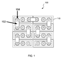
- FIG. 1 is a top view of an exemplary battery pack 100 composed of a plurality of battery cells 110.
- the battery pack 100 is illustrated with 8 battery cells 110.
- the battery cells 110 are coupled in series by electrically conducting power bars 102, which connect a positive electrode of one battery cell to a negative electrode of an adjacent battery cell.
- Such power bars 102 can be electrically connected to the cell electrodes by soldered or bolted contacts 104, etc.
- FIG. 2 schematically depicts a block diagram of a battery pack 200 with integrated supervisors 212, according to an embodiment of the invention.
- the battery pack 200 includes a plurality of battery cells 210 serially connected by power bars 202 (e.g., 202a, 202b). Each battery cell 210 has a positive electrode A and a negative electrode B. The individual ends of the power bars 202 may be electrically coupled to the respective cell electrodes by soldered or bolted contacts, or the like.
- FIG. 2 also shows an optional conversion resistor, Rconv, connected in series with the battery cells 210.
- An optional current monitor 220 can detect a voltage drop across the resistor Rconv, which effectively reflects the pack current flowing through the serially-connected battery cells 210 and thus may be used for purpose of supervision.
- the battery pack 200 may further include a pack controller 230 to control the operation of the battery pack 200 based on detected measurements and/or input commands.
- the battery cells 210 (as well as the current monitor 220, if applicable) may communicate with the pack controller 230 through a daisy chain of communication wires 206.
- a signal intended to be communicated between any battery cell 210 and the pack controller 230 may pass through other battery cells 210 (or other components, if any) located therebetween.
- one or more of the battery cells 210 may have an integrated supervisor 212 for at least contact detection for the battery cell 210.
- a supervisor 212 may be integrated within the battery cell 210.
- the supervisor 212 can be built into the battery pack 200 and external to the associated battery cell 210, preferably as close as possible to the battery cell being monitored.
- the battery cell 210 supplies voltages VDD and VSS for the associated supervisor 212, where the DC level of the communication wire 206 can be set based on (e.g., equal to) the VDD of the transmitting supervisor 212.
- the power bar 202 between each pair of battery cells 210 has the same (or substantially the same) potential as the connected cell electrodes, and thus can act as the signal ground (VSS) for the corresponding communication wire 206.
- the voltage difference between the power bar 202 and the corresponding communication line 206 is approximately equal to zero or (VDD-VSS), depending on which supervisor 212 is transmitting on the communication line 206.
- the supervisor 212 associated with the battery cell 210 is configured to measure a voltage difference between the power bar 202 and the corresponding communication wire 206, and may compare the detected voltage difference to a threshold value, so as to ascertain whether a contact is compromised (e.g., corroded, loose, or the like), as further described in details below.
- a contact e.g., corroded, loose, or the like
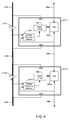
- FIG. 3A is a block diagram of a battery pack with integrated supervisors 212, according to a single-side supervision configuration in an embodiment of this invention.
- two battery cells 210-1 and 210-2 in the battery pack are shown, and they are connected to each other with a power bar 202b at nodes C and D.
- the battery cells 210-1 and 210-2 have supervisors 212-1 and 212-2 integrated therein, respectively.
- the segment BC or AD represents the electrode of the respective battery cell 210.
- Other battery cells in the battery pack can be configured similarly.
- the supervisor 212 each can include a digital circuit 326 for performing analysis on detected measurements or controlling operation of the battery cell 210 based on the measurements and/or commands from the pack controller 230 (see FIG. 2 ).
- a transmitter/receiver (TRx) 328 may also be provided for signal communication via the communication wires 206.
- the TRx 328 may receive information from the digital circuit 326 and communicate it to other battery cells 210 and/or to the pack controller 230 via the communication wires 206.
- the TRx 328 may receive a signal from other battery cells 210 and/or the pack controller 230 via the communication wires 206 and communicate it to the digital circuit 326.
- each of the supervisors 212 may include a voltage difference detector 312 on at least one electrode side of the associated battery cell 210, for measuring a voltage difference between the power bar 202 (e.g., 202a, 202b, 202c...) and the corresponding communication wire 206 (e.g., 206a, 206b, 206c). As mentioned above, such voltage difference reflects a contact condition between the power bar 202 and the cell electrodes. As shown in FIG. 3A , the voltage difference detector 312 is coupled to the negative electrode of the associated battery cell 210.
- the communication on the communication wire 206 can take place in the current domain or voltage domain. If the communication is in the current domain, the receiving side acts as virtual ground for the associated voltage difference detector 312, which is capable of performing a DC measurement between the power bar 202 and the communication line 206 directly. On the other hand, if the communication is in the voltage domain, the voltage difference measurement may take place when the transmitter's output is at ground potential. In addition, filtering or timing may be employed to separate a DC voltage difference between power bar and communication line from the communication signal on the communication line 206. Even no information needs to be communicated on the communication line 206, the digital circuit 326 may instruct the Trx 328 to transmit dummy signal on the communication line 206 based on scheduled timing, for purpose of voltage difference measurement. As each supervisor 212 (in particular, the digital circuit 326) knows what communication is ongoing on the communication line 206, the digital circuit 326 can control the voltage difference detector 312 to perform voltage difference measurement at appropriate times.
- the battery cell 210 supplies voltages VDD and VSS for the supervisor 212 from the positive electrode A and negative electrode B, respectively.
- the voltage difference detector 312-1 will detect a zero (or small) voltage difference between the power bar 202b and the communication wire 206b, when the TRx 328-1 receives signal communication on the communication wire 206b from the battery cell 210-2. Otherwise, if a contact C (or D) between the power bar 202b and the associated cell electrode is degraded and thus has an increased resistance, there will be an increased voltage drop on the degraded contact, causing the potential on the negative electrode B of the battery cell 210-1 to decrease.
- the voltage difference detector 312-1 will detect a voltage difference change between the power bar 202b and the communication wire 206b, when the TRx 328-1 receives on the communication wire 206b. If the detected voltage difference (e.g., the absolute value there of) is out of a predetermined threshold range (e.g., exceeding a predetermined threshold), the voltage difference detector 312-1 may assert a signal to indicate degraded contact of the power bar 202b. For example, the voltage difference detector 312-1 may send an alert signal to the TRx 328-1, which in turn transmits the alert signal to the pack controller 230.
- a predetermined threshold range e.g., exceeding a predetermined threshold
- the voltage difference detector 312-2 in the battery cell 210-2 may monitor the contact condition of the power bar 202c by measuring a voltage difference between the power bar 202c and the communication wire 206c, when the TRx 328-2 receives signal communication on the communication wire 206c. In the same way, it is possible to monitor all the contacts between the power bars 202 and the associated cell electrodes in the battery pack.
- the voltage difference detector 312 can be coupled to the positive electrode A of the associated battery cell 210, as shown in FIG. 3B .
- the voltage difference detector 312-2 in the battery cell 210-2 will detect a normal voltage difference between the power bar 202b and the communication wire 206b (e.g., VDD-VSS of the battery cell 210-1), when the TRx 328-2 receives signal communication on the communication wire 206b. Otherwise, if a contact C (or D) between the power bar 202b and the associated cell electrode is degraded and thus has an increased resistance, the potential on the positive electrode A of the battery cell 210-1 (VDD) will decrease.
- the voltage difference detector 312-2 will detect a voltage difference change between the power bar 202b and the communication wire 206b. If the detected voltage difference is out of a predetermined threshold range (e.g., below a predetermined threshold), the voltage difference detector 312-2 may assert a signal to indicate degraded contact of the power bar 202b.
- a predetermined threshold range e.g., below a predetermined threshold
- the voltage difference detector 312-1 in the battery cell 210-1 may monitor the contact condition of the power bar 202a by measuring a voltage difference between the power bar 202a and the communication wires 206a.
- each supervisor 212 having a voltage difference detector 312 on either the positive electrode A or negative electrode B of the associated battery cell 210, it is possible to monitor all the contacts between the power bars 202 and the associated cell electrodes in the battery pack.
- FIG. 4 is a block diagram of a battery pack with integrated supervisors 212, according to another embodiment of this invention.
- FIG. 4 is similar to FIG. 3 , except that the supervisor 212 is built external to the associated battery cell 210. Accordingly, the designations of nodes A and B represent the cell electrodes A and B as well as their contacts with the power bars 202.
- the battery cell 210 supplies voltages VDD and VSS for the associated supervisor 212 from the power bars 202 coupled to the positive electrode A and negative electrode B, respectively.
- the voltage difference detector 312 may be coupled to power bar 202.
- the voltage difference detector 312-1 will detect a voltage difference change between the power bar 202b and the communication wire 206b, when the TRx 328-1 transmits on the communication wire 206b.
- the voltage difference between the power bar 202b and the communication wire 206b implicitly reflects the voltage across the battery cell 210-1. If the detected voltage difference is out of a predetermined threshold range (e.g., below a predetermined threshold), the voltage difference detector 312-1 may assert a signal to indicate degraded contact of the battery cell 210-1 with the power bar 202a or 202b.
- a predetermined threshold range e.g., below a predetermined threshold
- the voltage difference detector 312 is coupled to the power bar 202 on the positive electrode A of the associated battery cell 210 and the corresponding communication wire 206, a degraded contact A (or B) of the battery cell 210-1 causes the potential on power bar 202a to decrease.
- the voltage difference detector 312-2 in the battery cell 210-2 will detect a voltage difference change between the power bar 202b and the communication wire 206b, when the TRx 328-2 receives on the communication wire 206b. If the detected voltage difference is out of a predetermined threshold range (e.g., below a predetermined threshold), the voltage difference detector 312-2 may assert a signal to indicate degraded contact of the battery cell 210-1 with the power bar 202a or 202b. Each of the battery cells 210 may be detected similarly.
- FIG. 5 is a block diagram of a battery cell in a battery pack with integrated supervisors, according to a both-side supervision configuration in an embodiment of this invention.
- the supervisor 212 may include a voltage difference detector 312 on both electrode sides of the battery cell 210.
- a voltage difference detector 312a is coupled to the power bar 202a and the corresponding communication wire 206a
- a voltage difference detector 312b is coupled to the power bar 202b and the corresponding communication wire 206b.
- the voltage difference detectors 312a and 312b operate similarly as the aforementioned voltage difference detectors 312 coupled to the positive and negative electrode sides, respectively.
- the supervisor 212 is shown as being integrated within the battery cell 210, the supervisor 212 may be built external to the battery cell 210, in a similar way as shown in FIG. 4 . Having two voltage difference detectors in each supervisor can always monitor the power bar 202 and the corresponding communication wire 206, irrespective of the direction of signal communication on the communication wire 206, thereby providing redundancy to achieve a high automotive safety requirement (e.g. ASIL), which is desirable in automotive applications.
- ASIL automotive safety requirement
- the supervisor 212 may further include an ADC 322 for monitoring a voltage across the battery cell 210, a temperature sensor 324 for continuously monitoring the temperature within the battery cell 210, a pressure sensor (not shown), as well as other sensors for measuring other parameters of the battery cell 210.
- the digital circuit 326 may receive and analyze the various measurements to determine the state of health of the battery cell over time, and to control the operation of the battery cell 210 based on the measurements or commands from the pack controller 230.
- the voltage difference detector 312 described above may be implemented with a comparator, which is configured to compare the measured voltage difference (or the absolute value thereof) to a predetermined threshold value. Once the measured voltage difference exceeds the threshold value, the comparator may trip to signal the digital circuit 326 or the pack controller 230.
- the threshold range (or threshold value) may be programmable or configurable, to optimize the system for different applications or usage scenarios. Such threshold range (or threshold value) may be determined based on the normal range (or normal value) and an appropriate margin. By example and without limitation, suppose a normal contact has a typical resistance of 0.1mOhm and the pack current has a peak value of 200A, resulting a peak contact voltage of 20mV which is in the "normal" range. An appropriate threshold value for the comparator might be set as 40mV, which would allow a contact resistance that has been doubled. The margins depend on the specific application and the overall constraints imposed on the battery pack.
- the voltage difference detectors 312 as described above may be implemented with Schmitt triggers.
- the Schmitt trigger is a type of comparator with a built-in trip voltage and hysteresis. This way, the voltage difference between each power bar and its associated communication line can always be measured, irrespective of the direction of signal communication on the communication wire 206.
- the voltage difference detector 312 may be implemented with an Analog-to-Digital Converter (ADC) to sense the voltage difference between the power bar 202 and communication wire 206.
- ADC Analog-to-Digital Converter
- the ADC may convert the measured voltage difference to a digital value and send it to the digital circuit 326 for processing.
- the digital circuit 326 may comprise a comparator or a software routine to determine whether the voltage difference is higher or lower than the threshold value.
- An advantage of digitizing is that the measured "contact" voltage can be divided by the pack current, so the contact resistance can be measured to a desired accuracy.
- the ADC 322 may be time-multiplexed to alternately convert the cell voltage or the measured voltage difference. Accordingly, the voltage difference detector 312 can be eliminated.
- the information detected by the voltage difference detector 312, among other measurements monitored by the supervisor 212, may be transmitted to the pack controller 230 through TRx 328 and the daisy chain of communication wires 206.
- an OK/NOK signal indicating that the voltage across a power bar contact is below/above a threshold may be transmitted to the pack controller 230.
- the supervisor 212 may send the measured voltage difference to the pack controller 230, which then makes a determination as to whether the power bar contact is operating normally.
- the transmitted signal may include an identifier corresponding to the contact(s) being detected, such that the degraded contact(s) can be located accurately.
- any appropriate countermeasures may be taken if a degraded contact (e.g., due to corrosion, loose contact, etc.) is detected.
- the pack controller 230 may warn the user (e.g., a car driver) that the battery pack should be checked or repaired.
- the pack controller 230 may automatically cut off the battery pack upon detection of dramatic increase in the contact resistance either during charging or discharging, to protect the battery cells/pack from damage. Because the pack controller 230 can identify where the degraded contact is located, a user or technician can make correction very quickly and precisely. For example, a loose bolt may be fastened or a corroded connector may be replaced, before the battery degrades catastrophically.
- the embodiments described above provide a variety of advantages.
- the degradation (such as corrosion or loosening) of a contact can be detected by the cell supervisor. By simply monitoring the voltage difference between the power bar and the corresponding communication line, an increase of the contact resistance can be detected for each individual power bar in the battery pack. All required additional circuitry can be easily integrated into the cell supervisor. Such detection is beneficial to improve the performance of the battery pack, extend the battery lifetime between recharges, and avoid potential damage to the battery pack.
- the contact detection can be combined with other measurements, such as voltage, temperature, pressure, etc., without the need to add external components or wiring.
Landscapes
- Engineering & Computer Science (AREA)
- Physics & Mathematics (AREA)
- General Physics & Mathematics (AREA)
- Power Engineering (AREA)
- Mechanical Engineering (AREA)
- Sustainable Development (AREA)
- Sustainable Energy (AREA)
- Transportation (AREA)
- Life Sciences & Earth Sciences (AREA)
- Chemical Kinetics & Catalysis (AREA)
- Chemical & Material Sciences (AREA)
- Manufacturing & Machinery (AREA)
- Electrochemistry (AREA)
- General Chemical & Material Sciences (AREA)
- Secondary Cells (AREA)
- Battery Mounting, Suspending (AREA)
- Connection Of Batteries Or Terminals (AREA)
- Measurement Of Current Or Voltage (AREA)
- Charge And Discharge Circuits For Batteries Or The Like (AREA)
Abstract
Description
- This disclosure generally relates to battery packs, and more specifically to method and apparatus for supervision in battery packs.
- Battery packs formed with a number of series-connected battery cells are widely employed for power supply, especially in mobile appliances. As known, in (hybrid) electric vehicles, a battery pack is used to generate a high voltage to drive the motor. In such a battery pack, the number of battery cells are coupled in series by electrically conducting power bars, wherein each power bar can electrically couple a positive electrode of one battery cell to a negative electrode of an adjacent battery cell, e.g., by soldering or bolting.
- Each component on a current path in the battery pack is preferably designed to have a small resistance in order to reduce useless power dissipation, especially when a current flowing through the battery cells is large (e.g., several 100A). Usually, the contact resistance between the power bars and the battery electrodes may be taken into account. Moreover, this contact resistance will rise if the contact gets corroded, loose, aging, etc. If the pack current is high, even a contact resistance of just 1 milliohm (mΩ) would be unacceptable. For example, with a pack current of 100A, it would give rise to a power dissipation of 10W, which is undesirable. Furthermore, a high contact resistance would lead to a hotspot that can severely limit the lifetime of the battery cell involved. In case of severe corrosion, the temperature rise may even cause a fire or explosion.
- Accordingly, it is desirable for methods and systems for contact detection in battery packs.
- Method and apparatus for contact detection in battery packs are disclosed.
- In one embodiment, a battery pack is disclosed. The battery pack may comprise at least a first battery cell and a second battery cell, and a power bar for coupling a first electrode of the first battery cell to a second electrode of the second battery cell. The first battery cell may comprise a supervisor, which comprises: a transmitter/receiver for signal communication with the second battery cell via a communication wire; and a voltage difference detector coupled to the power bar and the communication wire, for detecting a voltage difference between the power bar and the communication wire. The supervisor may indicate degraded contact of the power bar if the detected voltage difference is out of a predetermined threshold range. In one aspect, the degraded contact comprises at least one of contact corrosion or loose-contact.
- The voltage difference detector may be configured to detect the voltage difference when the transmitter/receiver is receiving signal communication via the communication wire. The signal communication via the communication wire may occur in a current domain or voltage domain, and the voltage difference detector may detect a DC voltage difference between the power bar and the communication wire.
- In one aspect, the supervisor may further comprise a digital circuit coupled to the voltage difference detector, for analyzing the detected voltage difference. In one aspect, the battery pack may further comprise a pack controller for controlling operation of the battery pack, wherein the at least the first battery cell and the second battery cell communicate with the pack controller through a daisy chain of communication wires.
- In one aspect, the voltage difference detector may comprise at least one of a comparator or an Analog-to-Digital Converter (ADC). Alternatively, the voltage difference detector may comprise an Analog-to-Digital Converter (ADC) which alternately detects a voltage across two electrodes of the first battery cell or the voltage difference between the power bar and the communication wire. Alternatively, the voltage difference detector may comprise a Schmitt trigger.
- In one aspect, the supervisor may be integrated within the first battery cell, wherein the voltage difference detector is coupled to the first electrode of the first battery cell. Alternatively, the supervisor may be external to the first battery cell, wherein the voltage difference detector is coupled to the power bar. In one aspect, the supervisor may comprise a voltage difference detector coupled to each electrode of the first and/or second battery cell.
- In another embodiment, a battery cell is also disclosed. The battery cell may comprise a power bar coupling to an electrode of the battery cell for power transmission; and a supervisor. The supervisor may comprises a transmitter/receiver for signal communication from/to the supervisor; and a voltage difference detector coupled to the power bar and the communication wire, for detecting a voltage difference between the power bar and the communication wire. The supervisor may indicate degraded contact of the power bar if the detected voltage difference is out of a predetermined threshold range.
- In yet another embodiment, a method for monitoring a battery pack that comprises at least a first battery cell and a second battery cell coupled in series by a power bar is disclosed. The method may comprise: detecting a voltage difference between the power bar and a communication wire, wherein the communication wire is used for signal communication between the first battery cell and the second battery cell; and indicating degraded contact of the power bar if the detected voltage difference is out of a predetermined threshold range.
- With this invention, the (onset of) degradation (e.g., corrosion or loosening) of a contact can be detected by the cell supervisor, without the need to add external components or wires to the battery pack. By simply monitoring the voltage difference between the power bar and the corresponding communication line, an increase of the contact resistance can be measured for each individual power bar in the battery pack. All required additional circuitry can be easily integrated into the cell supervisor. Such detection is beneficial to improve the performance of the battery pack, extend the battery lifetime between recharges, and avoid potential damage to the battery pack.
- Further features and advantages will become apparent from the following and more particular description of the preferred embodiments of the invention, as illustrated in the accompanying drawings, in which like referenced numerals generally refer to the same parts or elements throughout the drawings, and in which:
-
FIG. 1 is a top view of an exemplary battery pack, according to an embodiment of the invention; -
FIG. 2 schematically depicts a block diagram of a battery pack with integrated supervisors, according to an embodiment of the invention; -
FIG. 3A is a block diagram of a battery pack with integrated supervisors, according to an embodiment of the invention; -
FIG. 3B is a block diagram of a battery pack with integrated supervisors, according to another embodiment of the invention; -
FIG. 4 is a block diagram of a battery pack with integrated supervisors, according to yet another embodiment of the invention; and -
FIG. 5 is a block diagram of a battery cell with integrated supervisors, according to an embodiment of the invention. - The detailed description set forth below in connection with the accompany drawings is intended as a description of exemplary embodiments of the present invention and is not intended to represent the only exemplary embodiments in which the present invention can be practiced. The detailed description includes specific details for the purpose of providing a thorough understanding of the exemplary embodiments of the specification. It will be apparent to those skilled in the art that the exemplary embodiments of the specification may be practiced without these specific details. In some instances, well known structures and devices are shown in block diagram form in order to avoid obscuring the exemplary embodiments presented herein.
- The term "example" or "exemplary" as used throughout this application is only by way of illustration, and not limitation. Further, it will be understood that when an element is referred to as being "connected to" or "coupled to" another element, it can be directly connected or coupled to the other element or intervening elements may be present. For reference numerals with letter character designations such as "202a" or "202b", the letter character designations may differentiate two like parts or elements present in the same figure. Such letter character designations may be omitted when it is intended that a reference numeral to encompass all parts having the same reference numeral in all Figures.
-
FIG. 1 is a top view of anexemplary battery pack 100 composed of a plurality ofbattery cells 110. For clarity, thebattery pack 100 is illustrated with 8battery cells 110. However, it should be understood that, a battery pack according this invention can have more or less battery cells. Thebattery cells 110 are coupled in series by electrically conductingpower bars 102, which connect a positive electrode of one battery cell to a negative electrode of an adjacent battery cell.Such power bars 102 can be electrically connected to the cell electrodes by soldered orbolted contacts 104, etc. -
FIG. 2 schematically depicts a block diagram of abattery pack 200 withintegrated supervisors 212, according to an embodiment of the invention. Thebattery pack 200 includes a plurality ofbattery cells 210 serially connected by power bars 202 (e.g., 202a, 202b). Eachbattery cell 210 has a positive electrode A and a negative electrode B. The individual ends of the power bars 202 may be electrically coupled to the respective cell electrodes by soldered or bolted contacts, or the like. -
FIG. 2 also shows an optional conversion resistor, Rconv, connected in series with thebattery cells 210. An optionalcurrent monitor 220 can detect a voltage drop across the resistor Rconv, which effectively reflects the pack current flowing through the serially-connectedbattery cells 210 and thus may be used for purpose of supervision. Thebattery pack 200 may further include apack controller 230 to control the operation of thebattery pack 200 based on detected measurements and/or input commands. The battery cells 210 (as well as thecurrent monitor 220, if applicable) may communicate with thepack controller 230 through a daisy chain of communication wires 206. In particular, a signal intended to be communicated between anybattery cell 210 and thepack controller 230 may pass through other battery cells 210 (or other components, if any) located therebetween. - According to an embodiment of this invention, one or more of the
battery cells 210 may have an integratedsupervisor 212 for at least contact detection for thebattery cell 210. Such asupervisor 212 may be integrated within thebattery cell 210. Alternatively, thesupervisor 212 can be built into thebattery pack 200 and external to the associatedbattery cell 210, preferably as close as possible to the battery cell being monitored. - According to an embodiment of this invention, the
battery cell 210 supplies voltages VDD and VSS for the associatedsupervisor 212, where the DC level of the communication wire 206 can be set based on (e.g., equal to) the VDD of the transmittingsupervisor 212. During a normal condition, the power bar 202 between each pair ofbattery cells 210 has the same (or substantially the same) potential as the connected cell electrodes, and thus can act as the signal ground (VSS) for the corresponding communication wire 206. The voltage difference between the power bar 202 and the corresponding communication line 206 is approximately equal to zero or (VDD-VSS), depending on whichsupervisor 212 is transmitting on the communication line 206. - However, if the contact between the power bar 202 and the cell electrode is degraded (e.g., corroded, loose, or otherwise compromised), a contact resistance between the power bar 202 and the cell electrode will increase and cause an increased voltage drop. Accordingly, the potential downstream in the current path from the degraded contact will decrease as compared to that in a normal situation, and the voltage difference between the power bar 202 and the corresponding communication line 206 will change. Therefore, it is possible for the
supervisor 212 to perform contact supervision by monitoring a voltage difference between the power bar 202 and the corresponding communication line 206. In particular, thesupervisor 212 associated with thebattery cell 210 is configured to measure a voltage difference between the power bar 202 and the corresponding communication wire 206, and may compare the detected voltage difference to a threshold value, so as to ascertain whether a contact is compromised (e.g., corroded, loose, or the like), as further described in details below. -
FIG. 3A is a block diagram of a battery pack withintegrated supervisors 212, according to a single-side supervision configuration in an embodiment of this invention. By way of illustration, two battery cells 210-1 and 210-2 in the battery pack are shown, and they are connected to each other with apower bar 202b at nodes C and D. The battery cells 210-1 and 210-2 have supervisors 212-1 and 212-2 integrated therein, respectively. Note that the segment BC or AD represents the electrode of therespective battery cell 210. Other battery cells in the battery pack can be configured similarly. - The
supervisor 212 each can include adigital circuit 326 for performing analysis on detected measurements or controlling operation of thebattery cell 210 based on the measurements and/or commands from the pack controller 230 (seeFIG. 2 ). A transmitter/receiver (TRx) 328 may also be provided for signal communication via the communication wires 206. For example, theTRx 328 may receive information from thedigital circuit 326 and communicate it toother battery cells 210 and/or to thepack controller 230 via the communication wires 206. Also, theTRx 328 may receive a signal fromother battery cells 210 and/or thepack controller 230 via the communication wires 206 and communicate it to thedigital circuit 326. - According to an embodiment of this invention, each of the
supervisors 212 may include a voltage difference detector 312 on at least one electrode side of the associatedbattery cell 210, for measuring a voltage difference between the power bar 202 (e.g., 202a, 202b, 202c...) and the corresponding communication wire 206 (e.g., 206a, 206b, 206c...). As mentioned above, such voltage difference reflects a contact condition between the power bar 202 and the cell electrodes. As shown inFIG. 3A , the voltage difference detector 312 is coupled to the negative electrode of the associatedbattery cell 210. - The communication on the communication wire 206 can take place in the current domain or voltage domain. If the communication is in the current domain, the receiving side acts as virtual ground for the associated voltage difference detector 312, which is capable of performing a DC measurement between the power bar 202 and the communication line 206 directly. On the other hand, if the communication is in the voltage domain, the voltage difference measurement may take place when the transmitter's output is at ground potential. In addition, filtering or timing may be employed to separate a DC voltage difference between power bar and communication line from the communication signal on the communication line 206. Even no information needs to be communicated on the communication line 206, the
digital circuit 326 may instruct theTrx 328 to transmit dummy signal on the communication line 206 based on scheduled timing, for purpose of voltage difference measurement. As each supervisor 212 (in particular, the digital circuit 326) knows what communication is ongoing on the communication line 206, thedigital circuit 326 can control the voltage difference detector 312 to perform voltage difference measurement at appropriate times. - With the
supervisor 212 being located within thebattery cell 210, thebattery cell 210 supplies voltages VDD and VSS for thesupervisor 212 from the positive electrode A and negative electrode B, respectively. In a normal condition, the voltage difference detector 312-1 will detect a zero (or small) voltage difference between thepower bar 202b and thecommunication wire 206b, when the TRx 328-1 receives signal communication on thecommunication wire 206b from the battery cell 210-2. Otherwise, if a contact C (or D) between thepower bar 202b and the associated cell electrode is degraded and thus has an increased resistance, there will be an increased voltage drop on the degraded contact, causing the potential on the negative electrode B of the battery cell 210-1 to decrease. Consequently, the voltage difference detector 312-1 will detect a voltage difference change between thepower bar 202b and thecommunication wire 206b, when the TRx 328-1 receives on thecommunication wire 206b. If the detected voltage difference (e.g., the absolute value there of) is out of a predetermined threshold range (e.g., exceeding a predetermined threshold), the voltage difference detector 312-1 may assert a signal to indicate degraded contact of thepower bar 202b. For example, the voltage difference detector 312-1 may send an alert signal to the TRx 328-1, which in turn transmits the alert signal to thepack controller 230. - Similarly, the voltage difference detector 312-2 in the battery cell 210-2 may monitor the contact condition of the
power bar 202c by measuring a voltage difference between thepower bar 202c and thecommunication wire 206c, when the TRx 328-2 receives signal communication on thecommunication wire 206c. In the same way, it is possible to monitor all the contacts between the power bars 202 and the associated cell electrodes in the battery pack. - Alternatively, the voltage difference detector 312 can be coupled to the positive electrode A of the associated
battery cell 210, as shown inFIG. 3B . Normally, the voltage difference detector 312-2 in the battery cell 210-2 will detect a normal voltage difference between thepower bar 202b and thecommunication wire 206b (e.g., VDD-VSS of the battery cell 210-1), when the TRx 328-2 receives signal communication on thecommunication wire 206b. Otherwise, if a contact C (or D) between thepower bar 202b and the associated cell electrode is degraded and thus has an increased resistance, the potential on the positive electrode A of the battery cell 210-1 (VDD) will decrease. Consequently, the voltage difference detector 312-2 will detect a voltage difference change between thepower bar 202b and thecommunication wire 206b. If the detected voltage difference is out of a predetermined threshold range (e.g., below a predetermined threshold), the voltage difference detector 312-2 may assert a signal to indicate degraded contact of thepower bar 202b. - Similarly, the voltage difference detector 312-1 in the battery cell 210-1 may monitor the contact condition of the
power bar 202a by measuring a voltage difference between thepower bar 202a and thecommunication wires 206a. As above, with eachsupervisor 212 having a voltage difference detector 312 on either the positive electrode A or negative electrode B of the associatedbattery cell 210, it is possible to monitor all the contacts between the power bars 202 and the associated cell electrodes in the battery pack. -
FIG. 4 is a block diagram of a battery pack withintegrated supervisors 212, according to another embodiment of this invention.FIG. 4 is similar toFIG. 3 , except that thesupervisor 212 is built external to the associatedbattery cell 210. Accordingly, the designations of nodes A and B represent the cell electrodes A and B as well as their contacts with the power bars 202. In this configuration, thebattery cell 210 supplies voltages VDD and VSS for the associatedsupervisor 212 from the power bars 202 coupled to the positive electrode A and negative electrode B, respectively. Also, the voltage difference detector 312 may be coupled to power bar 202. - As above, when a degraded contact (e.g., node A or B of the battery cell 210-1) causes a potential decrease, the voltage difference detector 312-1 will detect a voltage difference change between the
power bar 202b and thecommunication wire 206b, when the TRx 328-1 transmits on thecommunication wire 206b. The voltage difference between thepower bar 202b and thecommunication wire 206b implicitly reflects the voltage across the battery cell 210-1. If the detected voltage difference is out of a predetermined threshold range (e.g., below a predetermined threshold), the voltage difference detector 312-1 may assert a signal to indicate degraded contact of the battery cell 210-1 with thepower bar battery cells 210 may be detected similarly. - Alternatively, if the voltage difference detector 312 is coupled to the power bar 202 on the positive electrode A of the associated
battery cell 210 and the corresponding communication wire 206, a degraded contact A (or B) of the battery cell 210-1 causes the potential onpower bar 202a to decrease. The voltage difference detector 312-2 in the battery cell 210-2 will detect a voltage difference change between thepower bar 202b and thecommunication wire 206b, when the TRx 328-2 receives on thecommunication wire 206b. If the detected voltage difference is out of a predetermined threshold range (e.g., below a predetermined threshold), the voltage difference detector 312-2 may assert a signal to indicate degraded contact of the battery cell 210-1 with thepower bar battery cells 210 may be detected similarly. -
FIG. 5 is a block diagram of a battery cell in a battery pack with integrated supervisors, according to a both-side supervision configuration in an embodiment of this invention. In particular, thesupervisor 212 may include a voltage difference detector 312 on both electrode sides of thebattery cell 210. For example, avoltage difference detector 312a is coupled to thepower bar 202a and thecorresponding communication wire 206a, and avoltage difference detector 312b is coupled to thepower bar 202b and thecorresponding communication wire 206b. Thevoltage difference detectors supervisor 212 is shown as being integrated within thebattery cell 210, thesupervisor 212 may be built external to thebattery cell 210, in a similar way as shown inFIG. 4 . Having two voltage difference detectors in each supervisor can always monitor the power bar 202 and the corresponding communication wire 206, irrespective of the direction of signal communication on the communication wire 206, thereby providing redundancy to achieve a high automotive safety requirement (e.g. ASIL), which is desirable in automotive applications. - Optionally, the
supervisor 212 may further include anADC 322 for monitoring a voltage across thebattery cell 210, atemperature sensor 324 for continuously monitoring the temperature within thebattery cell 210, a pressure sensor (not shown), as well as other sensors for measuring other parameters of thebattery cell 210. Thedigital circuit 326 may receive and analyze the various measurements to determine the state of health of the battery cell over time, and to control the operation of thebattery cell 210 based on the measurements or commands from thepack controller 230. - In one embodiment, the voltage difference detector 312 described above may be implemented with a comparator, which is configured to compare the measured voltage difference (or the absolute value thereof) to a predetermined threshold value. Once the measured voltage difference exceeds the threshold value, the comparator may trip to signal the
digital circuit 326 or thepack controller 230. The threshold range (or threshold value) may be programmable or configurable, to optimize the system for different applications or usage scenarios. Such threshold range (or threshold value) may be determined based on the normal range (or normal value) and an appropriate margin. By example and without limitation, suppose a normal contact has a typical resistance of 0.1mOhm and the pack current has a peak value of 200A, resulting a peak contact voltage of 20mV which is in the "normal" range. An appropriate threshold value for the comparator might be set as 40mV, which would allow a contact resistance that has been doubled. The margins depend on the specific application and the overall constraints imposed on the battery pack. - In another embodiment, the voltage difference detectors 312 as described above may be implemented with Schmitt triggers. The Schmitt trigger is a type of comparator with a built-in trip voltage and hysteresis. This way, the voltage difference between each power bar and its associated communication line can always be measured, irrespective of the direction of signal communication on the communication wire 206.
- In an alternative embodiment, the voltage difference detector 312 may be implemented with an Analog-to-Digital Converter (ADC) to sense the voltage difference between the power bar 202 and communication wire 206. The ADC may convert the measured voltage difference to a digital value and send it to the
digital circuit 326 for processing. In this situation, thedigital circuit 326 may comprise a comparator or a software routine to determine whether the voltage difference is higher or lower than the threshold value. An advantage of digitizing is that the measured "contact" voltage can be divided by the pack current, so the contact resistance can be measured to a desired accuracy. In some applications, theADC 322 may be time-multiplexed to alternately convert the cell voltage or the measured voltage difference. Accordingly, the voltage difference detector 312 can be eliminated. - The information detected by the voltage difference detector 312, among other measurements monitored by the
supervisor 212, may be transmitted to thepack controller 230 throughTRx 328 and the daisy chain of communication wires 206. As an option, either an OK/NOK signal indicating that the voltage across a power bar contact is below/above a threshold may be transmitted to thepack controller 230. Alternatively, thesupervisor 212 may send the measured voltage difference to thepack controller 230, which then makes a determination as to whether the power bar contact is operating normally. In addition, the transmitted signal may include an identifier corresponding to the contact(s) being detected, such that the degraded contact(s) can be located accurately. - Any appropriate countermeasures may be taken if a degraded contact (e.g., due to corrosion, loose contact, etc.) is detected. For example, the
pack controller 230 may warn the user (e.g., a car driver) that the battery pack should be checked or repaired. In addition or alternatively, thepack controller 230 may automatically cut off the battery pack upon detection of dramatic increase in the contact resistance either during charging or discharging, to protect the battery cells/pack from damage. Because thepack controller 230 can identify where the degraded contact is located, a user or technician can make correction very quickly and precisely. For example, a loose bolt may be fastened or a corroded connector may be replaced, before the battery degrades catastrophically. - The embodiments described above provide a variety of advantages. The degradation (such as corrosion or loosening) of a contact can be detected by the cell supervisor. By simply monitoring the voltage difference between the power bar and the corresponding communication line, an increase of the contact resistance can be detected for each individual power bar in the battery pack. All required additional circuitry can be easily integrated into the cell supervisor. Such detection is beneficial to improve the performance of the battery pack, extend the battery lifetime between recharges, and avoid potential damage to the battery pack. In addition, the contact detection can be combined with other measurements, such as voltage, temperature, pressure, etc., without the need to add external components or wiring.
- Aspects of the present invention are believed to be applicable to a variety of different types of devices, systems and arrangements involving batteries and/or battery control, including those involving automotive applications. While the present invention is not necessarily so limited, various aspects of the invention may be appreciated through a discussion of examples using this context.
- Although the various exemplary embodiments have been described in detail with particular reference to certain exemplary aspects thereof, it should be understood that the invention is capable of other embodiments and its details are capable of modifications in various obvious respects. As is readily apparent to those skilled in the art, variations and modifications can be affected while remaining within the scope of the invention. Accordingly, the foregoing disclosure, description, and figures are for illustrative purposes only and do not in any way limit the invention, which is defined only by the claims.
Claims (15)
- A battery pack comprising:at least a first battery cell and a second battery cell; anda power bar for coupling a first electrode of the first battery cell to a second electrode of the second battery cell, wherein the first battery cell comprises a supervisor, which comprises:a transmitter/receiver for signal communication with the second battery cell via a communication wire; anda voltage difference detector coupled to the power bar and the communication wire, for detecting a voltage difference between the power bar and the communication wire,wherein the supervisor indicates degraded contact of the power bar if the detected voltage difference is out of a predetermined threshold range.
- The battery pack of claim 1, wherein the voltage difference detector is configured to detect the voltage difference when the transmitter/receiver is receiving signal communication via the communication wire.
- The battery pack of claim 1, wherein the signal communication via the communication wire occurs in a current domain or voltage domain, and the voltage difference detector detects a DC voltage difference between the power bar and the communication wire.
- The battery pack of claim 1, wherein the degraded contact comprises at least one of contact corrosion or loose-contact.
- The battery pack of claim 1, wherein the voltage difference detector comprises at least one of a comparator, a Schmitt trigger, or an Analog-to-Digital Converter (ADC).
- The battery pack of claim 1, wherein:the supervisor is integrated within the first battery cell, wherein the voltage difference detector is coupled to the first electrode of the first battery cell; orthe supervisor is external to the first battery cell, wherein the voltage difference detector is coupled to the power bar.
- The battery pack of claim 1, wherein the supervisor further comprises a voltage difference detector coupled to another electrode of the first battery cell.
- A battery cell, comprising:a power bar coupled to an electrode of the battery cell for power transmission; anda supervisor, which comprises:a transmitter/receiver for signal communication from/to the supervisor; anda voltage difference detector coupled to the power bar and the communication wire, for detecting a voltage difference between the power bar and the communication wire,wherein the supervisor indicates degraded contact of the power bar if the detected voltage difference is out of a predetermined threshold range.
- The battery cell of claim 8, wherein the voltage difference detector is configured to detect the voltage difference when the transmitter/receiver is receiving signal communication via the communication wire.
- The battery cell of claim 8, wherein the degraded contact comprises at least one of contact corrosion or loose-contact.
- The battery cell of claim 8, wherein the voltage difference detector comprises at least one of a comparator, an Analog-to-Digital Converter (ADC), or a Schmitt trigger.
- A method for monitoring a battery pack that comprises at least a first battery cell and a second battery cell coupled in series by a power bar, the method comprising:detecting a voltage difference between the power bar and a communication wire, wherein the communication wire is used for signal communication between the first battery cell and the second battery cell; andindicating degraded contact of the power bar if the detected voltage difference is out of a predetermined threshold range.
- The method of claim 12, further comprising:detecting the voltage difference between the power bar and the communication wire at one of the first battery cell or the second battery cell which is receiving the signal communication.
- The method of claim 12, wherein the degraded contact comprises at least one of contact corrosion or loose-contact.
- The method of claim 12, further comprising:alternately detecting a voltage across two electrodes of the first or second battery cell or the voltage difference between the power bar and the communication wire.
Applications Claiming Priority (2)
| Application Number | Priority Date | Filing Date | Title |
|---|---|---|---|
| US14/565,574 US10826138B2 (en) | 2014-12-10 | 2014-12-10 | Method and apparatus for contact detection in battery packs |
| US14/807,414 US10620274B2 (en) | 2014-12-10 | 2015-07-23 | Method and apparatus for contact detection in battery packs |
Publications (2)
| Publication Number | Publication Date |
|---|---|
| EP3035067A1 true EP3035067A1 (en) | 2016-06-22 |
| EP3035067B1 EP3035067B1 (en) | 2019-10-16 |
Family
ID=54848456
Family Applications (2)
| Application Number | Title | Priority Date | Filing Date |
|---|---|---|---|
| EP15199257.5A Active EP3035068B1 (en) | 2014-12-10 | 2015-12-10 | Method and apparatus for detecting degraded contacts in battery packs |
| EP15199249.2A Active EP3035067B1 (en) | 2014-12-10 | 2015-12-10 | Method and apparatus for detecting faulty contacts in battery packs |
Family Applications Before (1)
| Application Number | Title | Priority Date | Filing Date |
|---|---|---|---|
| EP15199257.5A Active EP3035068B1 (en) | 2014-12-10 | 2015-12-10 | Method and apparatus for detecting degraded contacts in battery packs |
Country Status (4)
| Country | Link |
|---|---|
| US (1) | US10620274B2 (en) |
| EP (2) | EP3035068B1 (en) |
| JP (2) | JP6626704B2 (en) |
| CN (2) | CN105699776B (en) |
Cited By (3)
| Publication number | Priority date | Publication date | Assignee | Title |
|---|---|---|---|---|
| WO2020043385A1 (en) | 2018-08-29 | 2020-03-05 | Robert Bosch Gmbh | Method for identifying contact faults in a battery pack, and system for carrying out said method |
| EP3538881A4 (en) * | 2016-11-10 | 2020-07-08 | Camx Power, L.L.C. | Systems and processes for assessing electrochemical cell quality |
| DE102019115102A1 (en) * | 2019-06-05 | 2020-12-10 | Volkswagen Aktiengesellschaft | Monitoring arrangement for a battery system of a vehicle |
Families Citing this family (10)
| Publication number | Priority date | Publication date | Assignee | Title |
|---|---|---|---|---|
| DE102017208770B4 (en) * | 2017-05-23 | 2019-03-28 | Audi Ag | Method for checking a battery condition and tester for checking a battery condition |
| CN109119706B (en) * | 2017-06-22 | 2021-03-26 | 大唐恩智浦半导体有限公司 | Battery pack and battery module capable of detecting contact point |
| US10823786B2 (en) | 2017-07-28 | 2020-11-03 | Northstar Battery Company, Llc | Battery with internal monitoring system |
| CN107703350A (en) * | 2017-09-07 | 2018-02-16 | 上海斐讯数据通信技术有限公司 | The voltage monitoring system and method for a kind of equipment |
| KR102256094B1 (en) * | 2017-11-28 | 2021-05-25 | 주식회사 엘지에너지솔루션 | Battery back |
| US11018384B2 (en) | 2018-07-27 | 2021-05-25 | Nxp B.V. | Dual-cell supervisor circuit for high-voltage automotive battery packs |
| JP7034867B2 (en) | 2018-08-31 | 2022-03-14 | 株式会社ニューフレアテクノロジー | Abnormality judgment method and drawing device |
| KR102627843B1 (en) * | 2018-09-10 | 2024-01-19 | 주식회사 엘지에너지솔루션 | Battery management apparatus |
| JP2021151169A (en) * | 2020-03-23 | 2021-09-27 | 株式会社日立製作所 | Secondary battery device and control method for secondary battery |
| CN112060937A (en) * | 2020-09-20 | 2020-12-11 | 邹思良 | New energy automobile chassis |
Citations (6)
| Publication number | Priority date | Publication date | Assignee | Title |
|---|---|---|---|---|
| US6133709A (en) * | 1997-01-21 | 2000-10-17 | Metrixx Limited | Signalling system |
| US20100259221A1 (en) * | 2009-04-09 | 2010-10-14 | Tabatowski-Bush Ben A | Battery monitoring and control system and method of use |
| US20130021037A1 (en) * | 2011-01-21 | 2013-01-24 | Liebert Corporation | Wireless portable battery capacity test system |
| US20130245970A1 (en) * | 2012-03-15 | 2013-09-19 | O2 Micro Inc. | Apparatus and Method for Detecting Battery Abnormality and Cause Thereof |
| US20140278174A1 (en) * | 2013-03-15 | 2014-09-18 | Atieva, Inc. | Method of connecting cell voltage sensors |
| EP2803109A1 (en) * | 2012-01-13 | 2014-11-19 | Audi AG | Battery arrangement for a motor vehicle |
Family Cites Families (28)
| Publication number | Priority date | Publication date | Assignee | Title |
|---|---|---|---|---|
| US7352155B2 (en) | 2006-06-12 | 2008-04-01 | O2Micro International Ltd. | Apparatus and method for detecting battery pack voltage |
| JP2008076295A (en) * | 2006-09-22 | 2008-04-03 | Omron Corp | Battery life prediction system, battery life prediction method, communication terminal device, battery life prediction device, data transmission program, battery life predicting program, and computer-readable recording medium stored with program |
| US7755500B2 (en) * | 2006-12-01 | 2010-07-13 | O2 Micro, Inc. | Battery systems with embedded cell monitors |
| JP4722067B2 (en) | 2007-03-06 | 2011-07-13 | 日立ビークルエナジー株式会社 | Power storage device, storage battery management control device, and motor drive device |
| EP2264851B1 (en) * | 2008-02-29 | 2016-09-07 | Nissan Motor Co., Ltd. | Cell assembly monitor device |
| US8788225B2 (en) * | 2008-06-27 | 2014-07-22 | Johnson Controls-Saft Advanced Power Solutions Llc | Cell diagnostic system and method |
| JP5362428B2 (en) | 2009-04-24 | 2013-12-11 | 矢崎総業株式会社 | Disconnection detector |
| CN101713794B (en) * | 2009-10-23 | 2012-09-05 | 广州蓝奇电子实业有限公司 | Method for detecting poor contact of battery voltage testing terminals |
| US9140761B2 (en) * | 2009-12-25 | 2015-09-22 | Toyota Jidosha Kabushiki Kaisha | Battery pack failure detection device |
| JP5521795B2 (en) * | 2010-06-04 | 2014-06-18 | 日産自動車株式会社 | Battery control device |
| US8525477B2 (en) | 2010-07-15 | 2013-09-03 | O2Micro, Inc. | Assigning addresses to multiple cascade battery modules in electric or electric hybrid vehicles |
| US9000935B2 (en) | 2011-03-31 | 2015-04-07 | Elite Power Solutions Llc | Battery management system |
| JP5135506B2 (en) * | 2010-12-09 | 2013-02-06 | 三菱重工業株式会社 | Battery system |
| DE102011013394B4 (en) | 2011-03-09 | 2012-10-04 | Audi Ag | Battery for a vehicle and method of operating such a battery |
| JP5735098B2 (en) * | 2011-03-28 | 2015-06-17 | 三洋電機株式会社 | Battery system, electric vehicle, moving object, power storage device, and power supply device |
| US20120256598A1 (en) * | 2011-04-08 | 2012-10-11 | Neotec Semiconductor Ltd. | Battery Pack Detection Circuit |
| CN202093150U (en) * | 2011-04-22 | 2011-12-28 | 上海中科国嘉储能技术有限公司 | Battery pack detection system and battery power supply system |
| US9575135B2 (en) * | 2011-06-01 | 2017-02-21 | Datang Nxp Semiconductors Co., Ltd. | Battery monitoring circuit, apparatus and method |
| KR101255248B1 (en) * | 2011-07-04 | 2013-04-16 | 로베르트 보쉬 게엠베하 | Battery management system and control method thereof |
| US20130015875A1 (en) * | 2011-07-13 | 2013-01-17 | United Solar Ovonic Llc | Failure detection system for photovoltaic array |
| JP2013083514A (en) | 2011-10-07 | 2013-05-09 | Keihin Corp | Battery monitoring device |
| CN102508096A (en) * | 2011-10-29 | 2012-06-20 | 重庆大学 | Method for detecting connection state of connecting leads of power battery pack |
| CN202434723U (en) * | 2011-12-16 | 2012-09-12 | 广东高新兴通信股份有限公司 | Connecting device for monitoring battery |
| JP5439465B2 (en) * | 2011-12-26 | 2014-03-12 | 三菱重工業株式会社 | Battery system |
| JP6116061B2 (en) * | 2013-07-16 | 2017-04-19 | 横河電機株式会社 | Current sensor |
| CN103487717B (en) * | 2013-10-14 | 2016-03-09 | 奇瑞新能源汽车技术有限公司 | A kind of battery testing system and battery detection method |
| US20150219723A1 (en) | 2014-02-06 | 2015-08-06 | Donald H. Marvin | Continuous Monitoring Architecture for Power Storage Systems |
| CN204681110U (en) * | 2015-04-08 | 2015-09-30 | 上海天懋道生新能源科技有限公司 | A kind of high-efficiency electric automobile charging system |
-
2015
- 2015-07-23 US US14/807,414 patent/US10620274B2/en active Active
- 2015-12-10 JP JP2015241299A patent/JP6626704B2/en active Active
- 2015-12-10 EP EP15199257.5A patent/EP3035068B1/en active Active
- 2015-12-10 EP EP15199249.2A patent/EP3035067B1/en active Active
- 2015-12-10 CN CN201510917015.9A patent/CN105699776B/en active Active
- 2015-12-10 CN CN201510918334.1A patent/CN105699777B/en active Active
- 2015-12-10 JP JP2015241295A patent/JP6626703B2/en active Active
Patent Citations (6)
| Publication number | Priority date | Publication date | Assignee | Title |
|---|---|---|---|---|
| US6133709A (en) * | 1997-01-21 | 2000-10-17 | Metrixx Limited | Signalling system |
| US20100259221A1 (en) * | 2009-04-09 | 2010-10-14 | Tabatowski-Bush Ben A | Battery monitoring and control system and method of use |
| US20130021037A1 (en) * | 2011-01-21 | 2013-01-24 | Liebert Corporation | Wireless portable battery capacity test system |
| EP2803109A1 (en) * | 2012-01-13 | 2014-11-19 | Audi AG | Battery arrangement for a motor vehicle |
| US20130245970A1 (en) * | 2012-03-15 | 2013-09-19 | O2 Micro Inc. | Apparatus and Method for Detecting Battery Abnormality and Cause Thereof |
| US20140278174A1 (en) * | 2013-03-15 | 2014-09-18 | Atieva, Inc. | Method of connecting cell voltage sensors |
Cited By (6)
| Publication number | Priority date | Publication date | Assignee | Title |
|---|---|---|---|---|
| EP3538881A4 (en) * | 2016-11-10 | 2020-07-08 | Camx Power, L.L.C. | Systems and processes for assessing electrochemical cell quality |
| US11196098B2 (en) | 2016-11-10 | 2021-12-07 | Camx Power Llc | Systems and processes for assessing electrochemical cell quality |
| US11749845B2 (en) | 2016-11-10 | 2023-09-05 | Camx Power Llc | Systems and processes for assessing electrochemical cell quality |
| WO2020043385A1 (en) | 2018-08-29 | 2020-03-05 | Robert Bosch Gmbh | Method for identifying contact faults in a battery pack, and system for carrying out said method |
| US11500036B2 (en) | 2018-08-29 | 2022-11-15 | Robert Bosch Gmbh | Method for recognizing contacting errors in a rechargeable battery pack, and system for carrying out the method |
| DE102019115102A1 (en) * | 2019-06-05 | 2020-12-10 | Volkswagen Aktiengesellschaft | Monitoring arrangement for a battery system of a vehicle |
Also Published As
| Publication number | Publication date |
|---|---|
| EP3035068A1 (en) | 2016-06-22 |
| US10620274B2 (en) | 2020-04-14 |
| US20160169980A1 (en) | 2016-06-16 |
| CN105699776A (en) | 2016-06-22 |
| JP2016115678A (en) | 2016-06-23 |
| CN105699777A (en) | 2016-06-22 |
| JP2016115679A (en) | 2016-06-23 |
| CN105699777B (en) | 2020-06-30 |
| JP6626704B2 (en) | 2019-12-25 |
| EP3035067B1 (en) | 2019-10-16 |
| CN105699776B (en) | 2020-04-17 |
| JP6626703B2 (en) | 2019-12-25 |
| EP3035068B1 (en) | 2019-10-16 |
Similar Documents
| Publication | Publication Date | Title |
|---|---|---|
| EP3035067B1 (en) | Method and apparatus for detecting faulty contacts in battery packs | |
| US10826138B2 (en) | Method and apparatus for contact detection in battery packs | |
| KR101473397B1 (en) | Apparatus and method for checking current sensor abnormality in battery pack | |
| GB2528290A (en) | Battery management | |
| KR20150132370A (en) | System and methods for detection of internal shorts in batteries | |
| US10120033B2 (en) | Battery sensor and battery monitoring system | |
| KR20100054153A (en) | Charging circuit, and battery pack and charging system equipped with same | |
| US9921270B2 (en) | Battery system with cell voltage detecting units | |
| KR102448292B1 (en) | Battery pack diagnostic apparatus | |
| EP2926155B1 (en) | High voltage service disconnect assembly and method for determining an isolation resistance fault of a battery pack | |
| JP6016754B2 (en) | Battery voltage detector | |
| JP2012208066A (en) | Battery voltage detection device | |
| CN105203958A (en) | Battery state monitoring circuit and battery device | |
| KR20200042238A (en) | System and method for diagnosing the connectivity of fuses, bms including a system for diagnosing the connectivity of fuses | |
| CN109119706B (en) | Battery pack and battery module capable of detecting contact point | |
| JP2013072711A (en) | Voltage detection circuit | |
| US10534041B2 (en) | Measuring arrangement for identifying a malfunction in an energy accumulator arrangement | |
| CN106329489B (en) | Battery monitoring system | |
| JP6507989B2 (en) | Battery monitoring device | |
| JP4775415B2 (en) | Voltage monitor circuit | |
| JP5843518B2 (en) | Disconnection detector | |
| US8816716B2 (en) | Diagnostic apparatus for erroneous installation of power storage stacks and vehicle | |
| KR102248736B1 (en) | Battery management system | |
| KR20230149838A (en) | battery monitoring unit | |
| WO2024033939A1 (en) | A system for diagnosing loose contact in a battery pack |
Legal Events
| Date | Code | Title | Description |
|---|---|---|---|
| PUAI | Public reference made under article 153(3) epc to a published international application that has entered the european phase |
Free format text: ORIGINAL CODE: 0009012 |
|
| AK | Designated contracting states |
Kind code of ref document: A1 Designated state(s): AL AT BE BG CH CY CZ DE DK EE ES FI FR GB GR HR HU IE IS IT LI LT LU LV MC MK MT NL NO PL PT RO RS SE SI SK SM TR |
|
| AX | Request for extension of the european patent |
Extension state: BA ME |
|
| STAA | Information on the status of an ep patent application or granted ep patent |
Free format text: STATUS: REQUEST FOR EXAMINATION WAS MADE |
|
| RIN1 | Information on inventor provided before grant (corrected) |
Inventor name: VAN LAMMEREN, JOOP |
|
| 17P | Request for examination filed |
Effective date: 20161220 |
|
| RBV | Designated contracting states (corrected) |
Designated state(s): AL AT BE BG CH CY CZ DE DK EE ES FI FR GB GR HR HU IE IS IT LI LT LU LV MC MK MT NL NO PL PT RO RS SE SI SK SM TR |
|
| RIC1 | Information provided on ipc code assigned before grant |
Ipc: G01R 31/36 20190101AFI20190327BHEP Ipc: B60L 58/21 20190101ALN20190327BHEP Ipc: G01R 31/04 20060101ALI20190327BHEP |
|
| GRAP | Despatch of communication of intention to grant a patent |
Free format text: ORIGINAL CODE: EPIDOSNIGR1 |
|
| STAA | Information on the status of an ep patent application or granted ep patent |
Free format text: STATUS: GRANT OF PATENT IS INTENDED |
|
| INTG | Intention to grant announced |
Effective date: 20190522 |
|
| GRAS | Grant fee paid |
Free format text: ORIGINAL CODE: EPIDOSNIGR3 |
|
| GRAA | (expected) grant |
Free format text: ORIGINAL CODE: 0009210 |
|
| STAA | Information on the status of an ep patent application or granted ep patent |
Free format text: STATUS: THE PATENT HAS BEEN GRANTED |
|
| AK | Designated contracting states |
Kind code of ref document: B1 Designated state(s): AL AT BE BG CH CY CZ DE DK EE ES FI FR GB GR HR HU IE IS IT LI LT LU LV MC MK MT NL NO PL PT RO RS SE SI SK SM TR |
|
| REG | Reference to a national code |
Ref country code: GB Ref legal event code: FG4D |
|
| REG | Reference to a national code |
Ref country code: CH Ref legal event code: EP |
|
| REG | Reference to a national code |
Ref country code: DE Ref legal event code: R096 Ref document number: 602015039826 Country of ref document: DE |
|
| REG | Reference to a national code |
Ref country code: IE Ref legal event code: FG4D |
|
| REG | Reference to a national code |
Ref country code: AT Ref legal event code: REF Ref document number: 1191798 Country of ref document: AT Kind code of ref document: T Effective date: 20191115 |
|
| REG | Reference to a national code |
Ref country code: NL Ref legal event code: MP Effective date: 20191016 |
|
| REG | Reference to a national code |
Ref country code: LT Ref legal event code: MG4D |
|
| REG | Reference to a national code |
Ref country code: AT Ref legal event code: MK05 Ref document number: 1191798 Country of ref document: AT Kind code of ref document: T Effective date: 20191016 |
|
| PG25 | Lapsed in a contracting state [announced via postgrant information from national office to epo] |
Ref country code: NO Free format text: LAPSE BECAUSE OF FAILURE TO SUBMIT A TRANSLATION OF THE DESCRIPTION OR TO PAY THE FEE WITHIN THE PRESCRIBED TIME-LIMIT Effective date: 20200116 Ref country code: GR Free format text: LAPSE BECAUSE OF FAILURE TO SUBMIT A TRANSLATION OF THE DESCRIPTION OR TO PAY THE FEE WITHIN THE PRESCRIBED TIME-LIMIT Effective date: 20200117 Ref country code: BG Free format text: LAPSE BECAUSE OF FAILURE TO SUBMIT A TRANSLATION OF THE DESCRIPTION OR TO PAY THE FEE WITHIN THE PRESCRIBED TIME-LIMIT Effective date: 20200116 Ref country code: NL Free format text: LAPSE BECAUSE OF FAILURE TO SUBMIT A TRANSLATION OF THE DESCRIPTION OR TO PAY THE FEE WITHIN THE PRESCRIBED TIME-LIMIT Effective date: 20191016 Ref country code: PL Free format text: LAPSE BECAUSE OF FAILURE TO SUBMIT A TRANSLATION OF THE DESCRIPTION OR TO PAY THE FEE WITHIN THE PRESCRIBED TIME-LIMIT Effective date: 20191016 Ref country code: LT Free format text: LAPSE BECAUSE OF FAILURE TO SUBMIT A TRANSLATION OF THE DESCRIPTION OR TO PAY THE FEE WITHIN THE PRESCRIBED TIME-LIMIT Effective date: 20191016 Ref country code: LV Free format text: LAPSE BECAUSE OF FAILURE TO SUBMIT A TRANSLATION OF THE DESCRIPTION OR TO PAY THE FEE WITHIN THE PRESCRIBED TIME-LIMIT Effective date: 20191016 Ref country code: AT Free format text: LAPSE BECAUSE OF FAILURE TO SUBMIT A TRANSLATION OF THE DESCRIPTION OR TO PAY THE FEE WITHIN THE PRESCRIBED TIME-LIMIT Effective date: 20191016 Ref country code: SE Free format text: LAPSE BECAUSE OF FAILURE TO SUBMIT A TRANSLATION OF THE DESCRIPTION OR TO PAY THE FEE WITHIN THE PRESCRIBED TIME-LIMIT Effective date: 20191016 Ref country code: FI Free format text: LAPSE BECAUSE OF FAILURE TO SUBMIT A TRANSLATION OF THE DESCRIPTION OR TO PAY THE FEE WITHIN THE PRESCRIBED TIME-LIMIT Effective date: 20191016 Ref country code: PT Free format text: LAPSE BECAUSE OF FAILURE TO SUBMIT A TRANSLATION OF THE DESCRIPTION OR TO PAY THE FEE WITHIN THE PRESCRIBED TIME-LIMIT Effective date: 20200217 |
|
| PG25 | Lapsed in a contracting state [announced via postgrant information from national office to epo] |
Ref country code: RS Free format text: LAPSE BECAUSE OF FAILURE TO SUBMIT A TRANSLATION OF THE DESCRIPTION OR TO PAY THE FEE WITHIN THE PRESCRIBED TIME-LIMIT Effective date: 20191016 Ref country code: IS Free format text: LAPSE BECAUSE OF FAILURE TO SUBMIT A TRANSLATION OF THE DESCRIPTION OR TO PAY THE FEE WITHIN THE PRESCRIBED TIME-LIMIT Effective date: 20200224 Ref country code: HR Free format text: LAPSE BECAUSE OF FAILURE TO SUBMIT A TRANSLATION OF THE DESCRIPTION OR TO PAY THE FEE WITHIN THE PRESCRIBED TIME-LIMIT Effective date: 20191016 |
|
| PG25 | Lapsed in a contracting state [announced via postgrant information from national office to epo] |
Ref country code: AL Free format text: LAPSE BECAUSE OF FAILURE TO SUBMIT A TRANSLATION OF THE DESCRIPTION OR TO PAY THE FEE WITHIN THE PRESCRIBED TIME-LIMIT Effective date: 20191016 |
|
| REG | Reference to a national code |
Ref country code: DE Ref legal event code: R097 Ref document number: 602015039826 Country of ref document: DE |
|
| PG2D | Information on lapse in contracting state deleted |
Ref country code: IS |
|
| PG25 | Lapsed in a contracting state [announced via postgrant information from national office to epo] |
Ref country code: ES Free format text: LAPSE BECAUSE OF FAILURE TO SUBMIT A TRANSLATION OF THE DESCRIPTION OR TO PAY THE FEE WITHIN THE PRESCRIBED TIME-LIMIT Effective date: 20191016 Ref country code: DK Free format text: LAPSE BECAUSE OF FAILURE TO SUBMIT A TRANSLATION OF THE DESCRIPTION OR TO PAY THE FEE WITHIN THE PRESCRIBED TIME-LIMIT Effective date: 20191016 Ref country code: EE Free format text: LAPSE BECAUSE OF FAILURE TO SUBMIT A TRANSLATION OF THE DESCRIPTION OR TO PAY THE FEE WITHIN THE PRESCRIBED TIME-LIMIT Effective date: 20191016 Ref country code: RO Free format text: LAPSE BECAUSE OF FAILURE TO SUBMIT A TRANSLATION OF THE DESCRIPTION OR TO PAY THE FEE WITHIN THE PRESCRIBED TIME-LIMIT Effective date: 20191016 Ref country code: CZ Free format text: LAPSE BECAUSE OF FAILURE TO SUBMIT A TRANSLATION OF THE DESCRIPTION OR TO PAY THE FEE WITHIN THE PRESCRIBED TIME-LIMIT Effective date: 20191016 Ref country code: IS Free format text: LAPSE BECAUSE OF FAILURE TO SUBMIT A TRANSLATION OF THE DESCRIPTION OR TO PAY THE FEE WITHIN THE PRESCRIBED TIME-LIMIT Effective date: 20200216 |
|
| REG | Reference to a national code |
Ref country code: CH Ref legal event code: PL |
|
| PLBE | No opposition filed within time limit |
Free format text: ORIGINAL CODE: 0009261 |
|
| STAA | Information on the status of an ep patent application or granted ep patent |
Free format text: STATUS: NO OPPOSITION FILED WITHIN TIME LIMIT |
|
| REG | Reference to a national code |
Ref country code: BE Ref legal event code: MM Effective date: 20191231 |
|
| PG25 | Lapsed in a contracting state [announced via postgrant information from national office to epo] |
Ref country code: MC Free format text: LAPSE BECAUSE OF FAILURE TO SUBMIT A TRANSLATION OF THE DESCRIPTION OR TO PAY THE FEE WITHIN THE PRESCRIBED TIME-LIMIT Effective date: 20191016 Ref country code: IT Free format text: LAPSE BECAUSE OF FAILURE TO SUBMIT A TRANSLATION OF THE DESCRIPTION OR TO PAY THE FEE WITHIN THE PRESCRIBED TIME-LIMIT Effective date: 20191016 Ref country code: SK Free format text: LAPSE BECAUSE OF FAILURE TO SUBMIT A TRANSLATION OF THE DESCRIPTION OR TO PAY THE FEE WITHIN THE PRESCRIBED TIME-LIMIT Effective date: 20191016 Ref country code: SM Free format text: LAPSE BECAUSE OF FAILURE TO SUBMIT A TRANSLATION OF THE DESCRIPTION OR TO PAY THE FEE WITHIN THE PRESCRIBED TIME-LIMIT Effective date: 20191016 |
|
| 26N | No opposition filed |
Effective date: 20200717 |
|
| PG25 | Lapsed in a contracting state [announced via postgrant information from national office to epo] |
Ref country code: LU Free format text: LAPSE BECAUSE OF NON-PAYMENT OF DUE FEES Effective date: 20191210 Ref country code: IE Free format text: LAPSE BECAUSE OF NON-PAYMENT OF DUE FEES Effective date: 20191210 |
|
| PG25 | Lapsed in a contracting state [announced via postgrant information from national office to epo] |
Ref country code: LI Free format text: LAPSE BECAUSE OF NON-PAYMENT OF DUE FEES Effective date: 20191231 Ref country code: BE Free format text: LAPSE BECAUSE OF NON-PAYMENT OF DUE FEES Effective date: 20191231 Ref country code: SI Free format text: LAPSE BECAUSE OF FAILURE TO SUBMIT A TRANSLATION OF THE DESCRIPTION OR TO PAY THE FEE WITHIN THE PRESCRIBED TIME-LIMIT Effective date: 20191016 Ref country code: CH Free format text: LAPSE BECAUSE OF NON-PAYMENT OF DUE FEES Effective date: 20191231 |
|
| PG25 | Lapsed in a contracting state [announced via postgrant information from national office to epo] |
Ref country code: CY Free format text: LAPSE BECAUSE OF FAILURE TO SUBMIT A TRANSLATION OF THE DESCRIPTION OR TO PAY THE FEE WITHIN THE PRESCRIBED TIME-LIMIT Effective date: 20191016 |
|
| PG25 | Lapsed in a contracting state [announced via postgrant information from national office to epo] |
Ref country code: HU Free format text: LAPSE BECAUSE OF FAILURE TO SUBMIT A TRANSLATION OF THE DESCRIPTION OR TO PAY THE FEE WITHIN THE PRESCRIBED TIME-LIMIT; INVALID AB INITIO Effective date: 20151210 Ref country code: MT Free format text: LAPSE BECAUSE OF FAILURE TO SUBMIT A TRANSLATION OF THE DESCRIPTION OR TO PAY THE FEE WITHIN THE PRESCRIBED TIME-LIMIT Effective date: 20191016 |
|
| PG25 | Lapsed in a contracting state [announced via postgrant information from national office to epo] |
Ref country code: TR Free format text: LAPSE BECAUSE OF FAILURE TO SUBMIT A TRANSLATION OF THE DESCRIPTION OR TO PAY THE FEE WITHIN THE PRESCRIBED TIME-LIMIT Effective date: 20191016 |
|
| PG25 | Lapsed in a contracting state [announced via postgrant information from national office to epo] |
Ref country code: MK Free format text: LAPSE BECAUSE OF FAILURE TO SUBMIT A TRANSLATION OF THE DESCRIPTION OR TO PAY THE FEE WITHIN THE PRESCRIBED TIME-LIMIT Effective date: 20191016 |
|
| P01 | Opt-out of the competence of the unified patent court (upc) registered |
Effective date: 20230508 |
|
| PGFP | Annual fee paid to national office [announced via postgrant information from national office to epo] |
Ref country code: GB Payment date: 20231116 Year of fee payment: 9 |
|
| PGFP | Annual fee paid to national office [announced via postgrant information from national office to epo] |
Ref country code: FR Payment date: 20231122 Year of fee payment: 9 Ref country code: DE Payment date: 20231121 Year of fee payment: 9 |