EP3034902A1 - Brake disc and method for producing same - Google Patents
Brake disc and method for producing same Download PDFInfo
- Publication number
- EP3034902A1 EP3034902A1 EP14843625.6A EP14843625A EP3034902A1 EP 3034902 A1 EP3034902 A1 EP 3034902A1 EP 14843625 A EP14843625 A EP 14843625A EP 3034902 A1 EP3034902 A1 EP 3034902A1
- Authority
- EP
- European Patent Office
- Prior art keywords
- layer
- build
- main body
- disc main
- welding
- Prior art date
- Legal status (The legal status is an assumption and is not a legal conclusion. Google has not performed a legal analysis and makes no representation as to the accuracy of the status listed.)
- Granted
Links
- 238000004519 manufacturing process Methods 0.000 title claims description 20
- 238000003466 welding Methods 0.000 claims abstract description 159
- 238000001465 metallisation Methods 0.000 claims abstract description 7
- 239000002245 particle Substances 0.000 claims description 39
- 239000002923 metal particle Substances 0.000 claims description 36
- 239000000843 powder Substances 0.000 claims description 35
- 229910052751 metal Inorganic materials 0.000 claims description 29
- 239000002184 metal Substances 0.000 claims description 29
- 239000011159 matrix material Substances 0.000 claims description 23
- 239000000919 ceramic Substances 0.000 claims description 22
- 238000002844 melting Methods 0.000 claims description 17
- 230000008018 melting Effects 0.000 claims description 17
- WFKWXMTUELFFGS-UHFFFAOYSA-N tungsten Chemical compound [W] WFKWXMTUELFFGS-UHFFFAOYSA-N 0.000 claims description 12
- 229910052721 tungsten Inorganic materials 0.000 claims description 12
- 239000010937 tungsten Substances 0.000 claims description 12
- 239000000203 mixture Substances 0.000 claims description 8
- ZOKXTWBITQBERF-UHFFFAOYSA-N Molybdenum Chemical compound [Mo] ZOKXTWBITQBERF-UHFFFAOYSA-N 0.000 claims description 7
- 229910052750 molybdenum Inorganic materials 0.000 claims description 7
- 239000011733 molybdenum Substances 0.000 claims description 7
- 239000010955 niobium Substances 0.000 claims description 6
- 229910052758 niobium Inorganic materials 0.000 claims description 5
- GUCVJGMIXFAOAE-UHFFFAOYSA-N niobium atom Chemical compound [Nb] GUCVJGMIXFAOAE-UHFFFAOYSA-N 0.000 claims description 5
- 229910052715 tantalum Inorganic materials 0.000 claims description 5
- GUVRBAGPIYLISA-UHFFFAOYSA-N tantalum atom Chemical compound [Ta] GUVRBAGPIYLISA-UHFFFAOYSA-N 0.000 claims description 5
- 239000010410 layer Substances 0.000 description 198
- 239000000463 material Substances 0.000 description 40
- 239000007789 gas Substances 0.000 description 19
- PXHVJJICTQNCMI-UHFFFAOYSA-N Nickel Chemical compound [Ni] PXHVJJICTQNCMI-UHFFFAOYSA-N 0.000 description 15
- 238000005336 cracking Methods 0.000 description 9
- 229910045601 alloy Inorganic materials 0.000 description 7
- 239000000956 alloy Substances 0.000 description 7
- 239000000498 cooling water Substances 0.000 description 7
- 238000000034 method Methods 0.000 description 7
- 229910052759 nickel Inorganic materials 0.000 description 7
- 239000012159 carrier gas Substances 0.000 description 6
- 238000003475 lamination Methods 0.000 description 6
- 238000007751 thermal spraying Methods 0.000 description 6
- 229910000831 Steel Inorganic materials 0.000 description 5
- 230000000052 comparative effect Effects 0.000 description 5
- 239000010959 steel Substances 0.000 description 5
- 239000002344 surface layer Substances 0.000 description 5
- 238000004381 surface treatment Methods 0.000 description 5
- PNEYBMLMFCGWSK-UHFFFAOYSA-N aluminium oxide Inorganic materials [O-2].[O-2].[O-2].[Al+3].[Al+3] PNEYBMLMFCGWSK-UHFFFAOYSA-N 0.000 description 4
- 230000015556 catabolic process Effects 0.000 description 4
- 239000011247 coating layer Substances 0.000 description 4
- 230000007423 decrease Effects 0.000 description 4
- 238000006731 degradation reaction Methods 0.000 description 4
- 238000003780 insertion Methods 0.000 description 4
- 230000037431 insertion Effects 0.000 description 4
- 229910001018 Cast iron Inorganic materials 0.000 description 3
- 239000011324 bead Substances 0.000 description 3
- 230000000694 effects Effects 0.000 description 3
- 238000010438 heat treatment Methods 0.000 description 3
- 230000001788 irregular Effects 0.000 description 3
- XKRFYHLGVUSROY-UHFFFAOYSA-N Argon Chemical compound [Ar] XKRFYHLGVUSROY-UHFFFAOYSA-N 0.000 description 2
- 229910001339 C alloy Inorganic materials 0.000 description 2
- MCMNRKCIXSYSNV-UHFFFAOYSA-N Zirconium dioxide Chemical compound O=[Zr]=O MCMNRKCIXSYSNV-UHFFFAOYSA-N 0.000 description 2
- 229910052782 aluminium Inorganic materials 0.000 description 2
- XAGFODPZIPBFFR-UHFFFAOYSA-N aluminium Chemical compound [Al] XAGFODPZIPBFFR-UHFFFAOYSA-N 0.000 description 2
- 239000011651 chromium Substances 0.000 description 2
- 238000005520 cutting process Methods 0.000 description 2
- 238000010891 electric arc Methods 0.000 description 2
- 229910000856 hastalloy Inorganic materials 0.000 description 2
- 238000007689 inspection Methods 0.000 description 2
- 239000007788 liquid Substances 0.000 description 2
- 238000010791 quenching Methods 0.000 description 2
- 230000000171 quenching effect Effects 0.000 description 2
- 230000005855 radiation Effects 0.000 description 2
- QNRATNLHPGXHMA-XZHTYLCXSA-N (r)-(6-ethoxyquinolin-4-yl)-[(2s,4s,5r)-5-ethyl-1-azabicyclo[2.2.2]octan-2-yl]methanol;hydrochloride Chemical compound Cl.C([C@H]([C@H](C1)CC)C2)CN1[C@@H]2[C@H](O)C1=CC=NC2=CC=C(OCC)C=C21 QNRATNLHPGXHMA-XZHTYLCXSA-N 0.000 description 1
- 229910001316 Ag alloy Inorganic materials 0.000 description 1
- 229910000838 Al alloy Inorganic materials 0.000 description 1
- 229910000906 Bronze Inorganic materials 0.000 description 1
- OKTJSMMVPCPJKN-UHFFFAOYSA-N Carbon Chemical compound [C] OKTJSMMVPCPJKN-UHFFFAOYSA-N 0.000 description 1
- 229910000975 Carbon steel Inorganic materials 0.000 description 1
- VYZAMTAEIAYCRO-UHFFFAOYSA-N Chromium Chemical compound [Cr] VYZAMTAEIAYCRO-UHFFFAOYSA-N 0.000 description 1
- RYGMFSIKBFXOCR-UHFFFAOYSA-N Copper Chemical compound [Cu] RYGMFSIKBFXOCR-UHFFFAOYSA-N 0.000 description 1
- 229910000881 Cu alloy Inorganic materials 0.000 description 1
- BQCADISMDOOEFD-UHFFFAOYSA-N Silver Chemical compound [Ag] BQCADISMDOOEFD-UHFFFAOYSA-N 0.000 description 1
- 229910052786 argon Inorganic materials 0.000 description 1
- 239000010974 bronze Substances 0.000 description 1
- 229910052799 carbon Inorganic materials 0.000 description 1
- 239000010962 carbon steel Substances 0.000 description 1
- 229910052804 chromium Inorganic materials 0.000 description 1
- 229910052802 copper Inorganic materials 0.000 description 1
- 239000010949 copper Substances 0.000 description 1
- KUNSUQLRTQLHQQ-UHFFFAOYSA-N copper tin Chemical compound [Cu].[Sn] KUNSUQLRTQLHQQ-UHFFFAOYSA-N 0.000 description 1
- 230000007547 defect Effects 0.000 description 1
- 238000004299 exfoliation Methods 0.000 description 1
- 238000005242 forging Methods 0.000 description 1
- 239000001307 helium Substances 0.000 description 1
- 229910052734 helium Inorganic materials 0.000 description 1
- SWQJXJOGLNCZEY-UHFFFAOYSA-N helium atom Chemical compound [He] SWQJXJOGLNCZEY-UHFFFAOYSA-N 0.000 description 1
- 239000011261 inert gas Substances 0.000 description 1
- 229910010272 inorganic material Inorganic materials 0.000 description 1
- 239000011147 inorganic material Substances 0.000 description 1
- 238000010030 laminating Methods 0.000 description 1
- 239000000155 melt Substances 0.000 description 1
- 230000003534 oscillatory effect Effects 0.000 description 1
- 230000003647 oxidation Effects 0.000 description 1
- 238000007254 oxidation reaction Methods 0.000 description 1
- 230000000149 penetrating effect Effects 0.000 description 1
- 238000007747 plating Methods 0.000 description 1
- 238000003825 pressing Methods 0.000 description 1
- 229910052709 silver Inorganic materials 0.000 description 1
- 239000004332 silver Substances 0.000 description 1
- 239000000126 substance Substances 0.000 description 1
- 230000001629 suppression Effects 0.000 description 1
- 238000004227 thermal cracking Methods 0.000 description 1
- 238000011282 treatment Methods 0.000 description 1
Images


Classifications
-
- B—PERFORMING OPERATIONS; TRANSPORTING
- B23—MACHINE TOOLS; METAL-WORKING NOT OTHERWISE PROVIDED FOR
- B23K—SOLDERING OR UNSOLDERING; WELDING; CLADDING OR PLATING BY SOLDERING OR WELDING; CUTTING BY APPLYING HEAT LOCALLY, e.g. FLAME CUTTING; WORKING BY LASER BEAM
- B23K26/00—Working by laser beam, e.g. welding, cutting or boring
- B23K26/14—Working by laser beam, e.g. welding, cutting or boring using a fluid stream, e.g. a jet of gas, in conjunction with the laser beam; Nozzles therefor
- B23K26/1462—Nozzles; Features related to nozzles
- B23K26/1464—Supply to, or discharge from, nozzles of media, e.g. gas, powder, wire
- B23K26/1476—Features inside the nozzle for feeding the fluid stream through the nozzle
-
- B—PERFORMING OPERATIONS; TRANSPORTING
- B22—CASTING; POWDER METALLURGY
- B22F—WORKING METALLIC POWDER; MANUFACTURE OF ARTICLES FROM METALLIC POWDER; MAKING METALLIC POWDER; APPARATUS OR DEVICES SPECIALLY ADAPTED FOR METALLIC POWDER
- B22F10/00—Additive manufacturing of workpieces or articles from metallic powder
- B22F10/20—Direct sintering or melting
- B22F10/25—Direct deposition of metal particles, e.g. direct metal deposition [DMD] or laser engineered net shaping [LENS]
-
- B—PERFORMING OPERATIONS; TRANSPORTING
- B22—CASTING; POWDER METALLURGY
- B22F—WORKING METALLIC POWDER; MANUFACTURE OF ARTICLES FROM METALLIC POWDER; MAKING METALLIC POWDER; APPARATUS OR DEVICES SPECIALLY ADAPTED FOR METALLIC POWDER
- B22F7/00—Manufacture of composite layers, workpieces, or articles, comprising metallic powder, by sintering the powder, with or without compacting wherein at least one part is obtained by sintering or compression
- B22F7/06—Manufacture of composite layers, workpieces, or articles, comprising metallic powder, by sintering the powder, with or without compacting wherein at least one part is obtained by sintering or compression of composite workpieces or articles from parts, e.g. to form tipped tools
- B22F7/08—Manufacture of composite layers, workpieces, or articles, comprising metallic powder, by sintering the powder, with or without compacting wherein at least one part is obtained by sintering or compression of composite workpieces or articles from parts, e.g. to form tipped tools with one or more parts not made from powder
-
- B—PERFORMING OPERATIONS; TRANSPORTING
- B23—MACHINE TOOLS; METAL-WORKING NOT OTHERWISE PROVIDED FOR
- B23K—SOLDERING OR UNSOLDERING; WELDING; CLADDING OR PLATING BY SOLDERING OR WELDING; CUTTING BY APPLYING HEAT LOCALLY, e.g. FLAME CUTTING; WORKING BY LASER BEAM
- B23K26/00—Working by laser beam, e.g. welding, cutting or boring
- B23K26/34—Laser welding for purposes other than joining
-
- B—PERFORMING OPERATIONS; TRANSPORTING
- B23—MACHINE TOOLS; METAL-WORKING NOT OTHERWISE PROVIDED FOR
- B23K—SOLDERING OR UNSOLDERING; WELDING; CLADDING OR PLATING BY SOLDERING OR WELDING; CUTTING BY APPLYING HEAT LOCALLY, e.g. FLAME CUTTING; WORKING BY LASER BEAM
- B23K26/00—Working by laser beam, e.g. welding, cutting or boring
- B23K26/346—Working by laser beam, e.g. welding, cutting or boring in combination with welding or cutting covered by groups B23K5/00 - B23K25/00, e.g. in combination with resistance welding
- B23K26/348—Working by laser beam, e.g. welding, cutting or boring in combination with welding or cutting covered by groups B23K5/00 - B23K25/00, e.g. in combination with resistance welding in combination with arc heating, e.g. TIG [tungsten inert gas], MIG [metal inert gas] or plasma welding
-
- B—PERFORMING OPERATIONS; TRANSPORTING
- B61—RAILWAYS
- B61H—BRAKES OR OTHER RETARDING DEVICES SPECIALLY ADAPTED FOR RAIL VEHICLES; ARRANGEMENT OR DISPOSITION THEREOF IN RAIL VEHICLES
- B61H5/00—Applications or arrangements of brakes with substantially radial braking surfaces pressed together in axial direction, e.g. disc brakes
-
- F—MECHANICAL ENGINEERING; LIGHTING; HEATING; WEAPONS; BLASTING
- F16—ENGINEERING ELEMENTS AND UNITS; GENERAL MEASURES FOR PRODUCING AND MAINTAINING EFFECTIVE FUNCTIONING OF MACHINES OR INSTALLATIONS; THERMAL INSULATION IN GENERAL
- F16D—COUPLINGS FOR TRANSMITTING ROTATION; CLUTCHES; BRAKES
- F16D65/00—Parts or details
- F16D65/02—Braking members; Mounting thereof
- F16D65/12—Discs; Drums for disc brakes
- F16D65/123—Discs; Drums for disc brakes comprising an annular disc secured to a hub member; Discs characterised by means for mounting
- F16D65/124—Discs; Drums for disc brakes comprising an annular disc secured to a hub member; Discs characterised by means for mounting adapted for mounting on the wheel of a railway vehicle
-
- F—MECHANICAL ENGINEERING; LIGHTING; HEATING; WEAPONS; BLASTING
- F16—ENGINEERING ELEMENTS AND UNITS; GENERAL MEASURES FOR PRODUCING AND MAINTAINING EFFECTIVE FUNCTIONING OF MACHINES OR INSTALLATIONS; THERMAL INSULATION IN GENERAL
- F16D—COUPLINGS FOR TRANSMITTING ROTATION; CLUTCHES; BRAKES
- F16D65/00—Parts or details
- F16D65/02—Braking members; Mounting thereof
- F16D65/12—Discs; Drums for disc brakes
- F16D65/127—Discs; Drums for disc brakes characterised by properties of the disc surface; Discs lined with friction material
-
- F—MECHANICAL ENGINEERING; LIGHTING; HEATING; WEAPONS; BLASTING
- F16—ENGINEERING ELEMENTS AND UNITS; GENERAL MEASURES FOR PRODUCING AND MAINTAINING EFFECTIVE FUNCTIONING OF MACHINES OR INSTALLATIONS; THERMAL INSULATION IN GENERAL
- F16D—COUPLINGS FOR TRANSMITTING ROTATION; CLUTCHES; BRAKES
- F16D69/00—Friction linings; Attachment thereof; Selection of coacting friction substances or surfaces
- F16D69/02—Compositions of linings; Methods of manufacturing
- F16D69/027—Compositions based on metals or inorganic oxides
-
- B—PERFORMING OPERATIONS; TRANSPORTING
- B22—CASTING; POWDER METALLURGY
- B22F—WORKING METALLIC POWDER; MANUFACTURE OF ARTICLES FROM METALLIC POWDER; MAKING METALLIC POWDER; APPARATUS OR DEVICES SPECIALLY ADAPTED FOR METALLIC POWDER
- B22F10/00—Additive manufacturing of workpieces or articles from metallic powder
- B22F10/30—Process control
- B22F10/32—Process control of the atmosphere, e.g. composition or pressure in a building chamber
- B22F10/322—Process control of the atmosphere, e.g. composition or pressure in a building chamber of the gas flow, e.g. rate or direction
-
- B—PERFORMING OPERATIONS; TRANSPORTING
- B22—CASTING; POWDER METALLURGY
- B22F—WORKING METALLIC POWDER; MANUFACTURE OF ARTICLES FROM METALLIC POWDER; MAKING METALLIC POWDER; APPARATUS OR DEVICES SPECIALLY ADAPTED FOR METALLIC POWDER
- B22F10/00—Additive manufacturing of workpieces or articles from metallic powder
- B22F10/30—Process control
- B22F10/36—Process control of energy beam parameters
- B22F10/366—Scanning parameters, e.g. hatch distance or scanning strategy
-
- B—PERFORMING OPERATIONS; TRANSPORTING
- B22—CASTING; POWDER METALLURGY
- B22F—WORKING METALLIC POWDER; MANUFACTURE OF ARTICLES FROM METALLIC POWDER; MAKING METALLIC POWDER; APPARATUS OR DEVICES SPECIALLY ADAPTED FOR METALLIC POWDER
- B22F10/00—Additive manufacturing of workpieces or articles from metallic powder
- B22F10/60—Treatment of workpieces or articles after build-up
- B22F10/66—Treatment of workpieces or articles after build-up by mechanical means
-
- B—PERFORMING OPERATIONS; TRANSPORTING
- B22—CASTING; POWDER METALLURGY
- B22F—WORKING METALLIC POWDER; MANUFACTURE OF ARTICLES FROM METALLIC POWDER; MAKING METALLIC POWDER; APPARATUS OR DEVICES SPECIALLY ADAPTED FOR METALLIC POWDER
- B22F12/00—Apparatus or devices specially adapted for additive manufacturing; Auxiliary means for additive manufacturing; Combinations of additive manufacturing apparatus or devices with other processing apparatus or devices
- B22F12/20—Cooling means
-
- B—PERFORMING OPERATIONS; TRANSPORTING
- B33—ADDITIVE MANUFACTURING TECHNOLOGY
- B33Y—ADDITIVE MANUFACTURING, i.e. MANUFACTURING OF THREE-DIMENSIONAL [3-D] OBJECTS BY ADDITIVE DEPOSITION, ADDITIVE AGGLOMERATION OR ADDITIVE LAYERING, e.g. BY 3-D PRINTING, STEREOLITHOGRAPHY OR SELECTIVE LASER SINTERING
- B33Y10/00—Processes of additive manufacturing
-
- B—PERFORMING OPERATIONS; TRANSPORTING
- B33—ADDITIVE MANUFACTURING TECHNOLOGY
- B33Y—ADDITIVE MANUFACTURING, i.e. MANUFACTURING OF THREE-DIMENSIONAL [3-D] OBJECTS BY ADDITIVE DEPOSITION, ADDITIVE AGGLOMERATION OR ADDITIVE LAYERING, e.g. BY 3-D PRINTING, STEREOLITHOGRAPHY OR SELECTIVE LASER SINTERING
- B33Y80/00—Products made by additive manufacturing
-
- F—MECHANICAL ENGINEERING; LIGHTING; HEATING; WEAPONS; BLASTING
- F16—ENGINEERING ELEMENTS AND UNITS; GENERAL MEASURES FOR PRODUCING AND MAINTAINING EFFECTIVE FUNCTIONING OF MACHINES OR INSTALLATIONS; THERMAL INSULATION IN GENERAL
- F16D—COUPLINGS FOR TRANSMITTING ROTATION; CLUTCHES; BRAKES
- F16D65/00—Parts or details
- F16D65/02—Braking members; Mounting thereof
- F16D2065/13—Parts or details of discs or drums
- F16D2065/1304—Structure
- F16D2065/132—Structure layered
-
- F—MECHANICAL ENGINEERING; LIGHTING; HEATING; WEAPONS; BLASTING
- F16—ENGINEERING ELEMENTS AND UNITS; GENERAL MEASURES FOR PRODUCING AND MAINTAINING EFFECTIVE FUNCTIONING OF MACHINES OR INSTALLATIONS; THERMAL INSULATION IN GENERAL
- F16D—COUPLINGS FOR TRANSMITTING ROTATION; CLUTCHES; BRAKES
- F16D65/00—Parts or details
- F16D65/02—Braking members; Mounting thereof
- F16D2065/13—Parts or details of discs or drums
- F16D2065/134—Connection
- F16D2065/138—Connection to wheel
-
- F—MECHANICAL ENGINEERING; LIGHTING; HEATING; WEAPONS; BLASTING
- F16—ENGINEERING ELEMENTS AND UNITS; GENERAL MEASURES FOR PRODUCING AND MAINTAINING EFFECTIVE FUNCTIONING OF MACHINES OR INSTALLATIONS; THERMAL INSULATION IN GENERAL
- F16D—COUPLINGS FOR TRANSMITTING ROTATION; CLUTCHES; BRAKES
- F16D2200/00—Materials; Production methods therefor
- F16D2200/0004—Materials; Production methods therefor metallic
- F16D2200/0008—Ferro
- F16D2200/0013—Cast iron
-
- F—MECHANICAL ENGINEERING; LIGHTING; HEATING; WEAPONS; BLASTING
- F16—ENGINEERING ELEMENTS AND UNITS; GENERAL MEASURES FOR PRODUCING AND MAINTAINING EFFECTIVE FUNCTIONING OF MACHINES OR INSTALLATIONS; THERMAL INSULATION IN GENERAL
- F16D—COUPLINGS FOR TRANSMITTING ROTATION; CLUTCHES; BRAKES
- F16D2200/00—Materials; Production methods therefor
- F16D2200/0004—Materials; Production methods therefor metallic
- F16D2200/0026—Non-ferro
-
- F—MECHANICAL ENGINEERING; LIGHTING; HEATING; WEAPONS; BLASTING
- F16—ENGINEERING ELEMENTS AND UNITS; GENERAL MEASURES FOR PRODUCING AND MAINTAINING EFFECTIVE FUNCTIONING OF MACHINES OR INSTALLATIONS; THERMAL INSULATION IN GENERAL
- F16D—COUPLINGS FOR TRANSMITTING ROTATION; CLUTCHES; BRAKES
- F16D2200/00—Materials; Production methods therefor
- F16D2200/0034—Materials; Production methods therefor non-metallic
- F16D2200/0039—Ceramics
- F16D2200/0043—Ceramic base, e.g. metal oxides or ceramic binder
-
- F—MECHANICAL ENGINEERING; LIGHTING; HEATING; WEAPONS; BLASTING
- F16—ENGINEERING ELEMENTS AND UNITS; GENERAL MEASURES FOR PRODUCING AND MAINTAINING EFFECTIVE FUNCTIONING OF MACHINES OR INSTALLATIONS; THERMAL INSULATION IN GENERAL
- F16D—COUPLINGS FOR TRANSMITTING ROTATION; CLUTCHES; BRAKES
- F16D2250/00—Manufacturing; Assembly
- F16D2250/0038—Surface treatment
- F16D2250/0053—Hardening
-
- F—MECHANICAL ENGINEERING; LIGHTING; HEATING; WEAPONS; BLASTING
- F16—ENGINEERING ELEMENTS AND UNITS; GENERAL MEASURES FOR PRODUCING AND MAINTAINING EFFECTIVE FUNCTIONING OF MACHINES OR INSTALLATIONS; THERMAL INSULATION IN GENERAL
- F16D—COUPLINGS FOR TRANSMITTING ROTATION; CLUTCHES; BRAKES
- F16D2250/00—Manufacturing; Assembly
- F16D2250/0061—Joining
- F16D2250/0076—Welding, brazing
-
- Y—GENERAL TAGGING OF NEW TECHNOLOGICAL DEVELOPMENTS; GENERAL TAGGING OF CROSS-SECTIONAL TECHNOLOGIES SPANNING OVER SEVERAL SECTIONS OF THE IPC; TECHNICAL SUBJECTS COVERED BY FORMER USPC CROSS-REFERENCE ART COLLECTIONS [XRACs] AND DIGESTS
- Y02—TECHNOLOGIES OR APPLICATIONS FOR MITIGATION OR ADAPTATION AGAINST CLIMATE CHANGE
- Y02P—CLIMATE CHANGE MITIGATION TECHNOLOGIES IN THE PRODUCTION OR PROCESSING OF GOODS
- Y02P10/00—Technologies related to metal processing
- Y02P10/25—Process efficiency
Definitions
- the present invention relates to a brake disc and a manufacturing method thereof.
- a brake disc In a wheel or an axle of a railroad vehicle such as the Shinkansen, a brake disc is provided in order to obtain a braking force by pressing a brake pad thereon.
- the brake disc has a problem of being cracked or distorted due to an influence of heat generated during braking. Therefore, a brake disc is proposed in which the surface of a disc main body of the brake disc is coated with a material having excellent heat-resisting properties, whereby cracking or distortion generated due to brake heat can be suppressed.
- a blast treatment is carried out on the surface of the disc main body. That is, particles made of an inorganic material are sprayed onto the surface of the disc main body at a predetermined pressure, whereby an unevenly roughened layer is formed on the surface of the disc main body.
- a metallic bond layer is formed on the surface of the roughened layer, and then a ceramic having excellent heat-resisting properties and toughness such as zirconia is thermally sprayed onto the surface of the metallic bond layer, whereby a heat-resisting coating layer is formed on the surface of the metallic bond layer.
- the forged steel brake disc of the related art has heat-resisting properties and crack resistance, but is not subjected to any surface treatments. Therefore, the forged steel brake disc of the related art has a problem of being susceptible to heat generated during braking.
- Patent Document 2 discloses a manufacturing method of a brake disc for solving the above-described problem of heat influence.
- a surface treatment is carried out by means of welding, and plasma transferred arc welding (PTA welding) is carried out on the surface of the disc main body in order to alleviate heat influence represented by thermal cracking.
- PTA welding plasma transferred arc welding
- a brake disc is manufactured by laminating a plurality of layers of a welding material obtained by dispersing high-melting-point metal particles having a higher melting point than the disc main body in a matrix material on the surface of the disc main body that is attached to a rotary body integrally rotating with an axle by means of PTA welding.
- the disc main body melts into a build-up layer due to high-temperature plasma (the molten amount is in a range of 10% to 20%).
- the molten amount is in a range of 10% to 20%.
- the present invention has been made in consideration of the above-described circumstances, and an object of the present invention is to provide a brake disc which is capable of reducing the thickness of a disc main body and is capable of preventing the degradation of strength and functionality of a build-up layer, and a manufacturing method thereof.
- the present invention employs the following means.
- the build-up layer is laminated on the disc main body using laser metal deposition welding (LMD welding) in which a thermal influence is smaller than in PTA welding of the related art, preheating that is required in PTA welding of the related art is unnecessary, thermal strain generated during welding is suppressed, and thus it is possible to suppress the distortion of the disc main body.
- LMD welding laser metal deposition welding
- the build-up layer is laminated on the disc main body using LMD welding having a smaller thermal influence than PTA welding of the related art, it is possible to use ceramic particles having a relatively low melting point (for example, alumina) as the particles that are dispersed in the build-up layer.
- alumina relatively low melting point
- the inner layer (the first layer) of the build-up layer laminated on the disc main body does not include any high-melting-point metal particles, it is possible to enhance adhesion between the build-up layer and the disc main body.
- the high-melting-point metal particles in the outer layer (the second layer and the third layer) of the build-up layer remain in the outer layer as metal particles even after welding, it is possible to impart strong heat-resisting properties to the disc main body and to prevent the build-up layer from cracking after welding.
- a welding material obtained by dispersing high-melting-point metal particles having a higher melting point than the disc main body is laminated on the surface of the disc main body that is attached to a rotary body integrally rotating with an axle by means of LMD welding.
- quenching of the disc main body due to friction heat generated during braking while travelling is suppressed due to the build-up layer formed on the disc main body using LMD welding, and thus it is possible to suppress the generation of cracking or distortion on the surface of the disc main body and to impart both heat-resisting properties and thermal crack resistance to the brake disc.
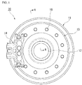
- FIG. 1 is a schematic front view showing the appearance of a Shinkansen braking apparatus 10 including a brake disc 13 according to the present embodiment.
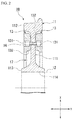
- FIG. 2 is a schematic cross-sectional view showing an A-A line cross-section in FIG. 1 .
- the Shinkansen braking apparatus 10 includes a substantially round wheel 11 (rotary body), an axle 12 inserted into the wheel 11, a brake disc 13 attached to the end surface of the wheel 11, and a brake pad 14 disposed close to the brake disc 13.
- the wheel 11 includes a flat plate part 111 having a constant thickness in an axial direction X of the wheel 11, a rim part 112 which is provided at the outer edge part of the flat plate part 111 in a radial direction Y of the wheel 11 and has a thickness in the axial direction X thicker than that of the flat plate part 111, a boss part 113 which is provided at the central part of the flat plate part 111 in the radial direction Y of the wheel 11 and has a thickness in the axial direction X thicker than those of the flat plate part 111 and the rim part 112, and an axis insertion hole 114 penetrating the boss part 113 in the axial direction X.
- the axle 12 is inserted into the axis insertion hole 114 of the wheel 11 and is fixed to the wheel 11.
- a driving apparatus a motor or the like
- the brake disc 13 plays a role of obtaining a braking force when the brake pad 14 is pressed thereon.
- the brake disc 13 is a flat plate member having a substantially circular ring shape.
- the outer diameter of the brake disc 13 is smaller than the inner diameter of the rim part 112 of the wheel 11.
- the inner diameter of the brake disc 13 is larger than the outer diameter of the boss part 113 of the wheel 11.
- the thickness of the brake disc 13 is substantially equal to the protruding height of the rim part 112 with respect to the flat plate part 111 of the wheel 11.
- a plurality of bolt insertion holes 131 are formed at predetermined intervals along the circumferential direction.
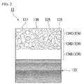
- FIG. 3 is a schematic cross-sectional view showing a vicinity of the surface of the brake disc 13.
- the brake disc 13 includes a disc main body 133 and a build-up layer 134 formed on the surface of the disc main body 133 by means of laser metal deposition welding (LMD welding).
- LMD welding laser metal deposition welding
- the disc main body 133 is the main body of the brake disc 13 obtained by forming forged steel, which is a steel product for forging, in a circular ring shape. Meanwhile, the material of the disc main body 133 is not limited to forged steel and may be carbon steel having excellent cost performance or pearlitic cast iron having excellent heat conducting properties and wear resistance.
- the build-up layer 134 is constituted of a laminate made up of a first build-up layer 134A laminated on the surface of the disc main body 133 by means of melt bonding, a second build-up layer 134B laminated on the surface of the first build-up layer 134A by means of melt bonding, and a third build-up layer 134C laminated on the surface of the second build-up layer 134B by means of melt bonding.
- the first build-up layer 134A forms an inner layer
- the second build-up layer 134B and the third build-up layer 134C form an outer layer
- the surface of the third build-up layer 134C located at the uppermost part serves as a friction surface 135 which is pressed by the brake pad 14. Meanwhile, as shown in FIG. 3 , a uniform integrated structure with no microstructural changes is formed between the respective build-up layers 134A to 134C due to melt bonding by means of welding.
- the first build-up layer 134A is a layer formed of a predetermined matrix 136.
- the Vickers hardness of the first build-up layer 134A is 220 [Hv] or higher and 270 [Hv] or lower.
- the thickness of the first build-up layer 134A is in a range of 1 [mm] to 5 [mm].
- the matrix 136 is, for example, a nickel-based alloy.
- the nickel-based alloy include HASTELLOY (registered trademark) C alloy.
- HASTELLOY C alloy refers to an alloy respectively containing, as chemical components, chromium (Cr): 15%, molybdenum (Mo): 16%, and tungsten (W): 4% in terms of % by mass with a remainder of nickel (Ni).
- the matrix 136 is not limited to the nickel-based alloy, and a material having high thermal conductivity such as copper and a copper alloy such as aluminum bronze, silver and a silver alloy, or aluminum or an aluminum alloy may be used as the matrix 136.
- the first build-up layer 134A initially laminated on the surface of the disc main body 133 does not include high-melting-point metal particles described below. Therefore, it is possible to enhance adhesion between the first build-up layer 134A and the disc main body 133.
- the second build-up layer 134B and the third build-up layer 134C are layers formed of the matrix 136 and contain high-melting-point metal particles 137 having a melting point higher than the melting point of the disc main body 133.
- the matrix 136 in the second build-up layer 134B and the third build-up layer 134C plays a role of homogeneously bonding the high-melting-point metal particles 137.
- the Vickers hardness of the second build-up layer 134B and the third build-up layer 134C is 220 [Hv] or higher and 270 [Hv] or lower.
- the second build-up layer 134B and the third build-up layer 134C only the high-melting-point metal particles 137 may be dispersed in the matrix 136.
- the second build-up layer 134B and the third build-up layer 134C include hard ceramic particles 138 (for example, alumina particles) together with the high-melting-point metal particles 137.
- the amount of the hard ceramic particles 138 in the second build-up layer 134B and the third build-up layer 134C is higher than 0% and 50% or lower in terms of % by mass.
- the hard ceramic particles 138 are added to the second build-up layer 134B and the third build-up layer 134C.
- the amount of the hard ceramic particles 138 in the second build-up layer 134B and the third build-up layer 134C is preferably higher than 0% and 50% or lower.
- the second build-up layer 134B constituted as described above is laminated on the surface of the first build-up layer 134A, and the third build-up layer 134C is laminated on the surface of the second build-up layer 134B, respectively, in a thickness in a range of approximately 1 mm to 5 mm. Meanwhile, basically, the third build-up layer 134C has the same constitution as the second build-up layer 134B.
- the high-melting-point metal particles 137 play a role of imparting strong heat-resisting properties to the disc main body 133.
- the high-melting-point metal particles 137 are particles of a metal having a higher melting point compared with the disc main body 133 and include molybdenum (Mo), tungsten (W), niobium (Nb), or tantalum (Ta), or a combination thereof.
- the amount of the high-melting-point metal particles 137 in the second build-up layer 134B and the third build-up layer 134C is higher than 0% and 80% or lower in terms of % by mass.
- particles having an average grain size of 75 ⁇ m or larger and 100 ⁇ m or smaller account for 70% to 80% of the total number of the particles, and particles having an average grain size of 10 ⁇ m or larger and 45 ⁇ m or smaller account for the remainder.
- the brake disc 13 constituted as described above is disposed on the flat plate part 111 of the wheel 11 in a state in which a side on which a notch part 132 is formed faces the wheel 11 side and is fixed to the wheel 11 using a fixing bolt 16 inserted into the bolt insertion hole 131.
- the outer diameter of the brake disc 13 is smaller than the inner diameter of the rim part 112.
- the inner diameter of the brake disc 13 is larger than the outer diameter of the boss part 113.
- a gap 17 having a predetermined width is formed between the brake disc 13 and the boss part 113 in a state in which the brake disc 13 is fixed to the flat plate part 111 of the wheel 11.
- the brake pad 14 is provided at a location opposite to the brake disc 13 in the radial direction Y of the wheel 11.
- the brake pad 14 is provided so as to be capable of moving in the axial direction X of the wheel 11.
- the friction surface 135 the surface of the third build-up layer 134C
- the brake pad 14 is separated from the brake disc 13, the rotation of the axle 12 is allowed.
- the build-up layer 134 is laminated on the surface of the disc main body 133 by means of LMD welding. Therefore, in the boundary surface between the disc main body 133 and the first build-up layer 134A, the adhesion strength between the disc main body 133 and the first build-up layer 134A improves due to melt bonding. Therefore, in a braking environment during high-speed travelling, it is possible to prevent the build-up layer 134 from being exfoliated from the surface of the disc main body 133.
- the Vickers hardness of the build-up layer 134 is 220 [Hv] or higher and 270 [Hv] or lower. As described above, the Vickers hardness of the build-up layer 134 is below 350 [Hv] which is a Vickers hardness that serves as a general rough standard determining whether cracks initiate and propagate. Therefore, even in a braking environment during high-speed travelling, cracking or distortion does not easily occur in the build-up layer 134.
- high toughness is imparted to the disc main body 133 by means of a heat treatment during the manufacturing thereof.
- heat generated from LMD welding heat generated by laser beams striking the disc main body 133
- a quenched layer (not shown) is generated, and thus the disc main body 133 is hardened.
- the quenched layer generated during the lamination of the first build-up layer 134A is tempered due to the heat applied during the lamination of the second build-up layer 134B. Therefore, toughness is imparted to the hardened disc main body 133.
- the quenched layer generated during the lamination of the first build-up layer 134A is tempered, and thus the toughness of the disc main body 133 further improves. As a result, even in a braking environment during high-speed travelling, cracking or distortion does not easily occur in the disc main body 133.
- the crack resistance of the disc main body 133 further improves.
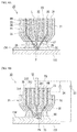
- FIG. 4A is a front cross-sectional view of the LMD welding apparatus 20 in the present embodiment.
- FIG. 4B is a front sectional view of a PTA welding apparatus 30 shown as a comparative example.
- the LMD welding apparatus 20 in the present embodiment includes a welding torch 21, a central hole 22 which is formed in the central part of the welding torch 21 and through which a laser beam L supplied from a laser oscillator (not shown) passes, and a cooling water supply path 23, a shield gas supply path 24, and a welding material supply path 25 which are respectively formed in a concentric shape around the central hole 22.
- the cooling water supply path 23 is disposed outside the central hole 22 and serves as a flow path through which cooling water RW is supplied.
- the shield gas supply path 24 and the welding material supply path 25 are disposed so as to be adjacent to each other outside the cooling water supply path 23.
- a shield gas SG is supplied to the shield gas supply path 24.
- a welding material 26 (metal powder) is supplied to the welding material supply path 25.
- a nozzle 27 is provided at the tip of the shield gas supply path 24, and the shield gas SG is sprayed toward the surface of the disc main body 133 from the nozzle 27.
- a nozzle 28 is provided at the tip of the welding material supply path 25, and the welding material 26 is sprayed toward the surface of the disc main body 133 from the nozzle 28.
- first metal powder that is particles of the matrix 136 is used as the welding material 26.
- second metal powder that is the powder mixture of the particles of the matrix 136, the high-melting-point metal particles 137, and the hard ceramic particles 138 is used as the welding material 26.
- the above-described welding material 26 is transported using a carrier gas CG which flows through the welding material supply path 25.
- an inert gas such as argon gas or helium gas is used.
- the oxidation of the disc main body 133 and the build-up layer 134 is prevented due to the shield gas SG supplied to the shield gas supply path 24.
- the laser beam L is radiated on the surface of the disc main body 133 from the welding torch 21, and the welding material 26 (the first metal powder or the second metal powder) is supplied to a laser irradiation position (a position indicated with a reference sign P in FIG. 4A ) using the carrier gas CG through the welding material supply path 25.
- the welding material 26 supplied to the laser irradiation position P is melted by applying a strong heat energy using the laser beam L.
- the build-up layer 134 is formed.
- the welding torch 21 is moved at a constant speed along the surface of the disc main body 133 at the same time as the radiation of the laser beam L and the supply of the welding material 26, it is possible to form the build-up layer 134 having a constant thickness on the surface of the disc main body 133.
- the welding torch 21 is reciprocally moved a plurality of times, it is possible to laminate the build-up layer 134 having a multilayer structure on the surface of the disc main body 133.
- the amount of heat input to the disc main body 133 is small, and heat is generated due to the laser beam L which is supplied from the laser oscillator (not shown) and is radiated on the disc main body 133.
- the laser beam diameter of the laser beam L and the movement speed of the laser beam L it is necessary to appropriately set the laser beam diameter of the laser beam L and the movement speed of the laser beam L.
- the focal diameter of the laser beam L is set to 5.4 [mm]
- the set voltage value of a manual focusing optics (MFO), which is a device that adjusts the focal distance of the laser beam L is set to 0.54 [V]
- the output of the laser beam L is set to 2700 [W].
- the flow rate of the shield gas SG is set to 15 [L/min]
- the rotation speed of the welding torch 21 is set to 10 [rpm]
- the flow rate of the carrier gas CG is set to 4 [L/min].
- the welding rate (the movement speed of the welding torch 21) is set to 500 [mm/min]
- the pitch width is set to 2.3 [mm].
- the PTA welding apparatus 30 mentioned as a comparative example includes a welding torch 31, a tungsten electrode 32 inserted into the central part of the welding torch 31, a main power supply 33 connected to the tungsten electrode 32 and the disc main body 133, and a pilot power supply 34 connected to the tungsten electrode 32 and the welding torch 31.
- an electrode hole 311 is formed in the central part of the welding torch 31, and a first flow path 312, a second flow path 313, and a third flow path 314 are formed in a concentric shape around the electrode hole 311.
- the tungsten electrode 32 is inserted into the electrode hole 311, and a pilot gas PG is supplied. Cooling water RW is supplied to the first flow path 312.
- a welding material 35 and a carrier gas CG are supplied to the second flow path 313.
- a shield gas SG is supplied to the third flow path 314. Meanwhile, the welding material 35 is a powder mixture of matrix particles and high-melting-point metal particles.
- the pilot gas PG when voltage is applied between the tungsten electrode 32 and the welding torch 31 using the pilot power supply 34, arc discharge is generated in the electrode hole 311, and thus the pilot gas PG turns into plasma.
- the pilot gas PG that has turned into plasma plasma gas
- the pilot gas is cooled using the cooling water RW supplied to the first flow path 312
- the pilot gas is thinly squeezed due to a so-called thermal pinch effect.
- the plasma gas is sprayed toward the disc main body 133 from a tip hole of the electrode hole 311 as a plasma arc PA having a high energy density.
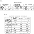
- FIG. 6 shows the characteristic comparison results between LMD welding that is carried out using the LMD welding apparatus 20 shown in FIG. 4A , PTA welding that is carried out using the PTA welding apparatus 30 shown in FIG. 4B , and plasma thermal spraying that is mentioned as another comparative example.
- the build-up thickness and the build-up amount are small, but the thermal load is low, and thus the amount of carbon molten into the build-up layer from the disc main body is small.
- the adhering force between the disc main body and the build-up layer is strong.
- the yield is high. Furthermore, although the porosity (welding defect) in plasma thermal spraying is in a range of 1% to 3%, the porosity in LMD welding is 0%.
- the relationship between the distance [mm] from the surface layer (surface) of the build-up layer and Vickers hardness [Hv] will be described with reference to FIG. 7 .
- the Vickers hardness was measured using a test specimen having a width of 50 [mm], a length of 150 [mm], and a thickness of 19 [mm].
- FIG. 7 is a graph showing the relationship between the distance [mm] from the surface layer of the build-up layer and Vickers hardness [Hv].
- the horizontal axis of FIG. 7 indicates the distance from the surface layer of the build-up layer in the thickness direction, and the vertical axis of FIG. 7 indicates Vickers hardness.
- round plots (O) in FIG. 7 indicate a case in which the first build-up layer is laminated on the disc main body using LMD welding.
- square plots ( ⁇ ) indicate a comparative example in which the first build-up layer is laminated using PTA welding without preheating the disc main body.
- Rhombic plots (0) indicate a comparative example in which the first build-up layer is laminated using PTA welding after preheating the disc main body to 250°C.
- the "thermally-influenced part” refers to a depth range of approximately 2.8 [mm] from the surface of the disc main body which is thermally influenced during welding.
- the "intrinsic main body part” refers to the entire part of the disc main body in the thickness direction.
- the reason therefor is that, in a case in which the build-up layer is formed using PTA welding, a quenched layer is generated in the disc main body due to an extremely high thermal influence, and thus the hardness of the disc main body increases.
- the thermal influence of LMD welding is weak, and the disc main body is thermally influenced only to an appropriate extent. Therefore, in a case in which the build-up layer is formed using LMD welding, the disc main body maintains high toughness.
- the Vickers hardness in a depth of 2 [mm] or more from the surface layer of the build-up layer is below 350 [Hv], which is considered as a general rough standard determining whether or not cracks initiate and propagate. Therefore, in a case in which the build-up layer is formed using LMD welding, in the disc main body, cracking or distortion does not easily occur.
- FIG. 8A shows a photo of the appearance of the build-up layer 134 formed on the surface of the disc main body 133 using the LMD welding apparatus 20 which is seen from above.
- FIG. 8B shows a cross-sectional microphoto of the build-up layer 134.
- FIG. 9A shows a photo of the appearance of the surface of the build-up layer 134.
- FIG. 9B shows the liquid penetrant inspection result of the build-up layer 134.
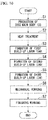
- FIG. 10 is a flowchart showing a manufacturing step of the brake disc 13 according to the present embodiment.
- the disc main body 133 is produced (Step S1).
- Step S1 an ingot having a predetermined composition is forged, rolled, or cast, thereby producing the disc main body 133.
- Step S2 a heat treatment of the disc main body 133 is carried out.
- Step S2 a heat treatment of the disc main body 133 is carried out so as to obtain desired characteristics of the disc main body 133 produced in Step S1, thereby adjusting the structure of the disc main body 133.
- Step S3 corresponding to a first step of a build-up layer-forming step in the present invention.
- the welding material 26 (the first metal powder) is melted by radiating the laser beam L on the surface of the disc main body 133 and supplying the welding material 26 to the position P irradiated with the laser beam L using the LMD welding apparatus 20, and the first build-up layer 134A is formed on the surface of the disc main body 133.
- the welding material 26 (the first metal powder) in Step S3 is the particle-formed (powder-formed) matrix 136 made of, for example, a nickel-based alloy.
- Step S4 corresponding to a second step of the build-up layer-forming step in the present invention.
- the second build-up layer 134B is formed on the surface of the first build-up layer 134A by radiating the laser beam L on the surface of the first build-up layer 134A and supplying the welding material 26 (the second metal powder) to the position P irradiated with the laser beam L so as to melt the welding material 26 using the LMD welding apparatus 20.
- the welding material 26 (the second metal powder) in Step S4 is a powder mixture of particles of the matrix 136 (for example, a nickel-based alloy), the high-melting-point metal particles 137 (for example, molybdenum), and the hard ceramic particles 138 (for example, alumina).
- the matrix 136 for example, a nickel-based alloy
- the high-melting-point metal particles 137 for example, molybdenum
- the hard ceramic particles 138 for example, alumina
- the amount of the hard ceramic particles 138 in the welding material 26 (the second metal powder) is higher than 0% and 50% or lower in terms of % by mass.
- the amount of the hard ceramic particles 138 in the second build-up layer 134B also becomes higher than 0% and 50% or lower in terms of % by mass.
- Step S5 corresponding to the second step of the build-up layer-forming step in the present invention.
- the third build-up layer 134C is formed on the surface of the second build-up layer 134B by radiating the laser beam L on the surface of the previously-formed second build-up layer 134B and supplying the welding material 26 made of the same second metal powder as above to the position P irradiated with the laser beam L using the LMD welding apparatus 20 so as to melt the welding material 26.
- the metallographic structure becomes uniform in the second build-up layer 134B and the third build-up layer 134C as a whole (refer to FIG. 3 ).
- the proportion of the high-melting-point metal particles 137 in the welding material 26 may be increased.
- the heat-resisting properties of the surface of the third build-up layer 134C that is, the friction surface 135 into which the brake pad 14 comes into direct contact
- Step S6 mechanical working of the brake disc 13 obtained by forming the build-up layer 134 on the surface of the disc main body 133 is carried out.
- Step S6 the outer form of the brake disc 13 is adjusted to be a desired outer form by means of cutting or the like.
- Step S7 finishing working of the brake disc 13 is carried out.
- Step S7 the friction surface 135 of the brake disc 13 is polished so that the friction surface 135 (the surface of the third build-up layer 134C) becomes a flat surface.
- the build-up layer 134 is laminated on the disc main body 133 using LMD welding having a smaller thermal influence than PTA welding of the related art, preheating which has been required in PTA welding of the related art is unnecessary, and thermal strain generated during welding is suppressed, and thus it is possible to suppress the strain distortion of the disc main body 133.
- the thickness of the disc main body 133 can be reduced.
- the build-up layer 134 is laminated on the disc main body 133 using LMD welding having a smaller thermal influence than PTA welding, it is possible to use ceramic particles having a relatively low melting point (for example, alumina) as the particles that are dispersed in the build-up layer 134.
- alumina relatively low melting point
- the first build-up layer 134A initially formed on the disc main body 133 is a nickel-based alloy layer not including any high-melting-point metal particles 137, it is possible to enhance adhesion between the build-up layer 134 and the disc main body 133.
- the high-melting-point metal particles 137 in the second build-up layer 134B and the third build-up layer 134C have a high melting point, the high-melting-point metal particles remain in the second layer 134B and the third layer 134C even after welding as metal particles. Therefore, it is possible to impart strong heat-resisting properties to the disc main body 133 and to prevent the build-up layer 134 from cracking after welding.
- the welding material 26 obtained by dispersing the high-melting-point metal particles 137 having a higher melting point than the disc main body 133 is laminated on the surface of the disc main body 133 that is attached to the wheel 11 (rotary body) integrally rotating with the axle by means of LMD welding.
- quenching of the disc main body 133 due to friction heat generated during braking while travelling is suppressed due to the build-up layer 134 formed on the disc main body 133 using LMD welding, and thus it is possible to suppress the generation of cracking or distortion on the surface of the disc main body 133 and to impart both heat-resisting properties and thermal crack resistance to the brake disc 13.
- the present invention relates to a brake disc which has a friction surface on which a brake pad is pressed and is capable of preventing thermal strain and the resulting distortion generated during welding, and a manufacturing method therefor.
Abstract
Description
- The present invention relates to a brake disc and a manufacturing method thereof.
- Priority is claimed on Japanese Patent Application No.
2013-191081, filed on September 13, 2013 - In a wheel or an axle of a railroad vehicle such as the Shinkansen, a brake disc is provided in order to obtain a braking force by pressing a brake pad thereon. Here, the brake disc has a problem of being cracked or distorted due to an influence of heat generated during braking. Therefore, a brake disc is proposed in which the surface of a disc main body of the brake disc is coated with a material having excellent heat-resisting properties, whereby cracking or distortion generated due to brake heat can be suppressed.
- For example, in a brake disc disclosed in
Patent Document 1, first, a blast treatment is carried out on the surface of the disc main body. That is, particles made of an inorganic material are sprayed onto the surface of the disc main body at a predetermined pressure, whereby an unevenly roughened layer is formed on the surface of the disc main body. In addition, a metallic bond layer is formed on the surface of the roughened layer, and then a ceramic having excellent heat-resisting properties and toughness such as zirconia is thermally sprayed onto the surface of the metallic bond layer, whereby a heat-resisting coating layer is formed on the surface of the metallic bond layer. According to the above-described constitution of the brake disc, since the conduction of heat generated during braking to the disc main body is reduced due to the heat-resisting coating layer, the generation of cracking or distortion of the disc main body is suppressed. - In this surface treatment technique for improving the thermal crack resistance of a brake disc which is disclosed in
Patent Document 1, the disc main body and the heat-resisting coating layer are strongly bonded together through the roughened layer and the metallic bond layer. Therefore, the bonding strength between the disc main body and the heat-resisting coating layer in the surface treatment technique disclosed inPatent Document 1 improves compared with surface treatment techniques of the related art such as a thermal spraying method or a plating method, but is still insufficient in a braking environment (high-speed rotation, oscillatory load, and high temperature) during high-speed travelling. - Meanwhile, as a technique of the related art for suppressing thermal cracks generated when a friction surface of the brake disc is cooled, there is a brake disc (clad disc) having a cast iron material fused to the surface of the disc main body, but there has been a problem of a low adhesion strength between the disc main body and the cast iron layer. In addition, the forged steel brake disc of the related art has heat-resisting properties and crack resistance, but is not subjected to any surface treatments. Therefore, the forged steel brake disc of the related art has a problem of being susceptible to heat generated during braking.
-
Patent Document 2 discloses a manufacturing method of a brake disc for solving the above-described problem of heat influence. - In the manufacturing method of a brake disc disclosed in
Patent Document 2, a surface treatment is carried out by means of welding, and plasma transferred arc welding (PTA welding) is carried out on the surface of the disc main body in order to alleviate heat influence represented by thermal cracking. - Specifically, in the manufacturing method of a brake disc disclosed in
Patent Document 2, a brake disc is manufactured by laminating a plurality of layers of a welding material obtained by dispersing high-melting-point metal particles having a higher melting point than the disc main body in a matrix material on the surface of the disc main body that is attached to a rotary body integrally rotating with an axle by means of PTA welding. -
- [Patent Document 1] Japanese Unexamined Patent Application, First Publication No.
2009-63072 - [Patent Document 2] Japanese Unexamined Patent Application, First Publication No.
2012-233530 - However, in the PTA welding disclosed in
Patent Document 2, preheating becomes necessary during welding, and thermal strain is generated due to the disc main body reaching an extremely high temperature, and thus the disc main body distorts. Therefore, there is a problem in that it is necessary to carry out a pretreatment in order to provide an inverse taper shape to the disc main body prior to welding. - In addition, in the PTA welding disclosed in
Patent Document 2, since a welding subject further thermally distorts as the size or length thereof increases, it is difficult to thin the disc main body. - In addition, in a case in which PTA welding is employed, the disc main body melts into a build-up layer due to high-temperature plasma (the molten amount is in a range of 10% to 20%). As a result, a problem of degradation of the strength and functionality of the build-up layer or a new problem of the generation of poor welding results such as beads, blowholes, or pits having irregular shapes is caused.
- In addition, in order to form a build-up layer on the surface of the disc main body by means ofPTA welding, it is necessary to generate high-temperature arc discharge, and thus there is another problem of an increase in running costs.
- The present invention has been made in consideration of the above-described circumstances, and an object of the present invention is to provide a brake disc which is capable of reducing the thickness of a disc main body and is capable of preventing the degradation of strength and functionality of a build-up layer, and a manufacturing method thereof.
- In order to solve the above-described problems and achieve the object, the present invention employs the following means.
- (1) According to a first aspect of the present invention, there is provided a brake disc that stops rotation of an axle when a brake pad is pressed on a surface of the brake disc, including a disc main body that is attached to a rotary body integrally rotating with the axle; and a plurality of build-up layers laminated on a surface of the disc main body, in which the build-up layers are laminated on the surface of the disc main body by means of laser metal deposition welding.
- (2) In the brake disc according to (1), the build-up layer may be constituted of a laminate formed of two or more layers of a predetermined matrix laminated on the surface of the disc main body, and the laminate may include an inner layer which is laminated on the disc main body and does not include high-melting-point metal particles having a higher melting point than the disc main body and an outer layer which is formed on the inner layer and includes the high-melting-point metal particles.
- (3) In the brake disc according to (2), the high-melting-point metal particles may include molybdenum, tungsten, niobium, or tantalum, or a combination thereof.
- (4) In the brake disc according to (2) or (3), the outer layer of the build-up layer may further include ceramic particles; and an amount of the ceramic particles in the outer layer may be higher than 0% and 50% or lower in terms of % by mass.
- (5) According to an aspect of the present invention, there is provided a manufacturing method of a brake disc that stops rotation of an axle when a brake pad is pressed on a surface of the brake disc, including a build-up layer-forming step of forming a build-up layer on a surface of a disc main body that is attached to a rotary body integrally rotating with the axle by means of laser metal deposition welding.
- (6) In the manufacturing method of a brake disc according to (5), the build-up layer-forming step may include a first step of forming an inner layer of the build-up layer on the surface of the brake main body by radiating laser beams on the surface of the disc main body and supplying a first metal powder to a position irradiated with the laser beams so as to melt the first metal powder; and a second step of forming an outer layer of the build-up layer on a surface of the inner layer by radiating laser beams on the surface of the inner layer and supplying a second metal powder to a position irradiated with the laser beams so as to melt the second metal powder. In addition, the first metal powder may be particles of a predetermined matrix, and the second metal powder may be a powder mixture of the particles of the matrix and high-melting-point metal particles having a melting point higher than a melting point of the disc main body.
- (7) In the manufacturing method of a brake disc according to (5) or (6), the high-melting-point metal particles may include molybdenum, tungsten, niobium, or tantalum, or a combination thereof.
- (8) In the manufacturing method of a brake disc according to any one of (5) to (7), the second metal powder may be a powder mixture of the particles of the matrix, the high-melting-point metal particles, and ceramic particles; and an amount of the ceramic particles in the second metal powder may be higher than 0% and 50% or lower in terms of % by mass.
- In the above-described aspect, since the build-up layer is laminated on the disc main body using laser metal deposition welding (LMD welding) in which a thermal influence is smaller than in PTA welding of the related art, preheating that is required in PTA welding of the related art is unnecessary, thermal strain generated during welding is suppressed, and thus it is possible to suppress the distortion of the disc main body. As a result, according to the above-described aspect, it is possible to reduce the thickness of the disc main body.
- In addition, in the above-described aspect, since LMD welding having a smaller thermal influence than PTA welding is used, it is also possible to prevent the disc main body from melting into the build-up layer. As a result, according to the above-described aspect, it is possible to prevent the degradation of the strength and functionality of the build-up layer. In addition, since it is also possible to suppress the generation of poor welding results such as beads, blowholes, or pits having irregular shapes in the build-up layer, it becomes possible to further prevent a decrease in the strength of the build-up layer.
- In addition, in the above-described aspect, since the build-up layer is laminated on the disc main body using LMD welding having a smaller thermal influence than PTA welding of the related art, it is possible to use ceramic particles having a relatively low melting point (for example, alumina) as the particles that are dispersed in the build-up layer.
- In addition, in the above-described aspect, since the inner layer (the first layer) of the build-up layer laminated on the disc main body does not include any high-melting-point metal particles, it is possible to enhance adhesion between the build-up layer and the disc main body. In addition, since the high-melting-point metal particles in the outer layer (the second layer and the third layer) of the build-up layer remain in the outer layer as metal particles even after welding, it is possible to impart strong heat-resisting properties to the disc main body and to prevent the build-up layer from cracking after welding.
- Furthermore, in the above-described aspect, a welding material obtained by dispersing high-melting-point metal particles having a higher melting point than the disc main body is laminated on the surface of the disc main body that is attached to a rotary body integrally rotating with an axle by means of LMD welding. According to the above-described aspect, quenching of the disc main body due to friction heat generated during braking while travelling is suppressed due to the build-up layer formed on the disc main body using LMD welding, and thus it is possible to suppress the generation of cracking or distortion on the surface of the disc main body and to impart both heat-resisting properties and thermal crack resistance to the brake disc.
-
-
FIG. 1 is a schematic front view showing an appearance of a Shinkansen braking apparatus including a brake disc according to an embodiment of the present invention. -
FIG. 2 is a schematic sectional view showing an A-A line cross-section inFIG. 1 . -
FIG. 3 is a schematic cross-sectional view showing a vicinity of a surface of the brake disc according to the present embodiment. -
FIG. 4A is a schematic constitutional view of an LMD welding apparatus that is used to form a build-up layer in the present embodiment. -
FIG. 4B is a schematic constitutional view of a PTA welding apparatus of the related art. -
FIG. 5 is a table showing welding conditions of the LMD welding apparatus. -
FIG. 6 is a table showing the characteristic comparison results between LMD welding, PTA welding, and plasma thermal spraying. -
FIG. 7 is a graph showing a relationship between the distance from a surface layer of the build-up layer and Vickers hardness. -
FIG. 8 shows a photo of the appearance of the build-up layer (A) seen from above and a cross-sectional microphoto of the build-up layer (B). -
FIG. 9 shows a photo of the appearance of the build-up layer (A) and a photo showing the liquid penetrant inspection result of the surface of the build-up layer (B). -
FIG. 10 is a flowchart showing a manufacturing method of a brake disc according to an embodiment of the present invention. - Hereinafter, an embodiment of the present invention will be described with reference to the accompanying drawings.
-
FIG. 1 is a schematic front view showing the appearance of aShinkansen braking apparatus 10 including abrake disc 13 according to the present embodiment. In addition,FIG. 2 is a schematic cross-sectional view showing an A-A line cross-section inFIG. 1 . - As shown in
FIG. 1 , theShinkansen braking apparatus 10 includes a substantially round wheel 11 (rotary body), anaxle 12 inserted into thewheel 11, abrake disc 13 attached to the end surface of thewheel 11, and abrake pad 14 disposed close to thebrake disc 13. - As shown in
FIGS. 1 and2 , thewheel 11 includes aflat plate part 111 having a constant thickness in an axial direction X of thewheel 11, arim part 112 which is provided at the outer edge part of theflat plate part 111 in a radial direction Y of thewheel 11 and has a thickness in the axial direction X thicker than that of theflat plate part 111, aboss part 113 which is provided at the central part of theflat plate part 111 in the radial direction Y of thewheel 11 and has a thickness in the axial direction X thicker than those of theflat plate part 111 and therim part 112, and anaxis insertion hole 114 penetrating theboss part 113 in the axial direction X. - As shown in
FIGS. 1 and2 , theaxle 12 is inserted into theaxis insertion hole 114 of thewheel 11 and is fixed to thewheel 11. When theaxle 12 is rotary-driven using a driving apparatus (a motor or the like), not shown, thewheel 11 and theaxle 12 rotate integrally with each other. - The
brake disc 13 plays a role of obtaining a braking force when thebrake pad 14 is pressed thereon. As shown inFIG. 1 , thebrake disc 13 is a flat plate member having a substantially circular ring shape. The outer diameter of thebrake disc 13 is smaller than the inner diameter of therim part 112 of thewheel 11. The inner diameter of thebrake disc 13 is larger than the outer diameter of theboss part 113 of thewheel 11. In addition, as shown inFIG. 2 , the thickness of thebrake disc 13 is substantially equal to the protruding height of therim part 112 with respect to theflat plate part 111 of thewheel 11. Furthermore, as shown inFIGS. 1 and2 , in thebrake disc 13, a plurality of bolt insertion holes 131 are formed at predetermined intervals along the circumferential direction. -
FIG. 3 is a schematic cross-sectional view showing a vicinity of the surface of thebrake disc 13. Thebrake disc 13 includes a discmain body 133 and a build-up layer 134 formed on the surface of the discmain body 133 by means of laser metal deposition welding (LMD welding). - The disc
main body 133 is the main body of thebrake disc 13 obtained by forming forged steel, which is a steel product for forging, in a circular ring shape. Meanwhile, the material of the discmain body 133 is not limited to forged steel and may be carbon steel having excellent cost performance or pearlitic cast iron having excellent heat conducting properties and wear resistance. - The build-
up layer 134 is constituted of a laminate made up of a first build-uplayer 134A laminated on the surface of the discmain body 133 by means of melt bonding, a second build-up layer 134B laminated on the surface of the first build-uplayer 134A by means of melt bonding, and a third build-up layer 134C laminated on the surface of the second build-up layer 134B by means of melt bonding. - Meanwhile, in the build-up layer 134 (134A to 134C) on the disc
main body 133, the first build-uplayer 134A forms an inner layer, and the second build-up layer 134B and the third build-up layer 134C form an outer layer. - In addition, the surface of the third build-
up layer 134C located at the uppermost part serves as afriction surface 135 which is pressed by thebrake pad 14. Meanwhile, as shown inFIG. 3 , a uniform integrated structure with no microstructural changes is formed between the respective build-uplayers 134A to 134C due to melt bonding by means of welding. - As shown in
FIG. 3 , the first build-uplayer 134A is a layer formed of apredetermined matrix 136. The Vickers hardness of the first build-uplayer 134A is 220 [Hv] or higher and 270 [Hv] or lower. The thickness of the first build-uplayer 134A is in a range of 1 [mm] to 5 [mm]. - The
matrix 136 is, for example, a nickel-based alloy. Examples of the nickel-based alloy include HASTELLOY (registered trademark) C alloy. Here, HASTELLOY C alloy refers to an alloy respectively containing, as chemical components, chromium (Cr): 15%, molybdenum (Mo): 16%, and tungsten (W): 4% in terms of % by mass with a remainder of nickel (Ni). Meanwhile, thematrix 136 is not limited to the nickel-based alloy, and a material having high thermal conductivity such as copper and a copper alloy such as aluminum bronze, silver and a silver alloy, or aluminum or an aluminum alloy may be used as thematrix 136. - The first build-up
layer 134A initially laminated on the surface of the discmain body 133 does not include high-melting-point metal particles described below. Therefore, it is possible to enhance adhesion between the first build-uplayer 134A and the discmain body 133. - As shown in
FIG. 3 , the second build-up layer 134B and the third build-up layer 134C are layers formed of thematrix 136 and contain high-melting-point metal particles 137 having a melting point higher than the melting point of the discmain body 133. Thematrix 136 in the second build-up layer 134B and the third build-up layer 134C plays a role of homogeneously bonding the high-melting-point metal particles 137. The Vickers hardness of the second build-up layer 134B and the third build-up layer 134C is 220 [Hv] or higher and 270 [Hv] or lower. Here, in the second build-up layer 134B and the third build-up layer 134C, only the high-melting-point metal particles 137 may be dispersed in thematrix 136. However, in the present embodiment, the second build-up layer 134B and the third build-up layer 134C include hard ceramic particles 138 (for example, alumina particles) together with the high-melting-point metal particles 137. The amount of the hardceramic particles 138 in the second build-up layer 134B and the third build-up layer 134C is higher than 0% and 50% or lower in terms of % by mass. - In the field of build-up welding, since it is necessary to suppress the friction coefficient of the surface of the build-up layer at an extremely low level, it is usual not to add ceramic particles to the build-up layer. However, in the present embodiment, in order to obtain a braking force required for the
brake disc 13, the hardceramic particles 138 are added to the second build-up layer 134B and the third build-up layer 134C. From the viewpoint of the average friction coefficient, the wear amount, and the suppression of grain boundary exfoliation between theceramic particles 138 and thematrix 136, the amount of the hardceramic particles 138 in the second build-up layer 134B and the third build-up layer 134C is preferably higher than 0% and 50% or lower. - The second build-
up layer 134B constituted as described above is laminated on the surface of the first build-uplayer 134A, and the third build-up layer 134C is laminated on the surface of the second build-up layer 134B, respectively, in a thickness in a range of approximately 1 mm to 5 mm. Meanwhile, basically, the third build-up layer 134C has the same constitution as the second build-up layer 134B. - The high-melting-
point metal particles 137 play a role of imparting strong heat-resisting properties to the discmain body 133. The high-melting-point metal particles 137 are particles of a metal having a higher melting point compared with the discmain body 133 and include molybdenum (Mo), tungsten (W), niobium (Nb), or tantalum (Ta), or a combination thereof. - The amount of the high-melting-
point metal particles 137 in the second build-up layer 134B and the third build-up layer 134C is higher than 0% and 80% or lower in terms of % by mass. - In addition, among the high-melting-
point metal particles 137, particles having an average grain size of 75 µm or larger and 100 µm or smaller account for 70% to 80% of the total number of the particles, and particles having an average grain size of 10 µm or larger and 45 µm or smaller account for the remainder. - As shown in
FIG. 2 , thebrake disc 13 constituted as described above is disposed on theflat plate part 111 of thewheel 11 in a state in which a side on which anotch part 132 is formed faces thewheel 11 side and is fixed to thewheel 11 using a fixingbolt 16 inserted into thebolt insertion hole 131. - In addition, as described above, the outer diameter of the
brake disc 13 is smaller than the inner diameter of therim part 112. The inner diameter of thebrake disc 13 is larger than the outer diameter of theboss part 113. - Therefore, as shown in
FIG. 2 , agap 17 having a predetermined width is formed between thebrake disc 13 and theboss part 113 in a state in which thebrake disc 13 is fixed to theflat plate part 111 of thewheel 11. - As shown in
FIG. 1 , thebrake pad 14 is provided at a location opposite to thebrake disc 13 in the radial direction Y of thewheel 11. Although not shown in detail, thebrake pad 14 is provided so as to be capable of moving in the axial direction X of thewheel 11. When thebrake pad 14 is moved toward thebrake disc 13, the friction surface 135 (the surface of the third build-up layer 134C) of thebrake disc 13 is pressed by thebrake pad 14. In such a case, a braking force that stops theaxle 12 which integrally rotates with thebrake disc 13 is generated. On the other hand, when thebrake pad 14 is separated from thebrake disc 13, the rotation of theaxle 12 is allowed. - Next, the effect of the
brake disc 13 according to the present embodiment will be described. In thebrake disc 13 according to the present embodiment, the build-up layer 134 is laminated on the surface of the discmain body 133 by means of LMD welding. Therefore, in the boundary surface between the discmain body 133 and the first build-uplayer 134A, the adhesion strength between the discmain body 133 and the first build-uplayer 134A improves due to melt bonding. Therefore, in a braking environment during high-speed travelling, it is possible to prevent the build-up layer 134 from being exfoliated from the surface of the discmain body 133. - In addition, the Vickers hardness of the build-
up layer 134 is 220 [Hv] or higher and 270 [Hv] or lower. As described above, the Vickers hardness of the build-up layer 134 is below 350 [Hv] which is a Vickers hardness that serves as a general rough standard determining whether cracks initiate and propagate. Therefore, even in a braking environment during high-speed travelling, cracking or distortion does not easily occur in the build-up layer 134. - In addition, high toughness is imparted to the disc
main body 133 by means of a heat treatment during the manufacturing thereof. During the lamination of the first build-uplayer 134A, when heat generated from LMD welding (heat generated by laser beams striking the disc main body 133) is applied to the discmain body 133, a quenched layer (not shown) is generated, and thus the discmain body 133 is hardened. - Meanwhile, during the lamination of the second build-
up layer 134B, since heat generated due to LMD welding is transferred to the discmain body 133 through the first build-uplayer 134A, the amount of heat transferred to the discmain body 133 decreases. Therefore, the quenched layer generated during the lamination of the first build-uplayer 134A is tempered due to the heat applied during the lamination of the second build-up layer 134B. Therefore, toughness is imparted to the hardened discmain body 133. - Furthermore, during the lamination of the third build-
up layer 134C, since heat generated due to LMD welding is transferred to the discmain body 133 through the second build-up layer 134B and the first build-uplayer 134A, the amount of heat transferred to the discmain body 133 further decreases. Therefore, similar to the above-described case, the quenched layer generated during the lamination of the first build-uplayer 134A is tempered, and thus the toughness of the discmain body 133 further improves. As a result, even in a braking environment during high-speed travelling, cracking or distortion does not easily occur in the discmain body 133. - Meanwhile, after the beginning of the use of the
brake disc 13, since the quenched layer generated in the discmain body 133 is further tempered due to heat generated during braking, the crack resistance of the discmain body 133 further improves. - Next, an
LMD welding apparatus 20 which is used to laminate the build-up layer 134 on the surface of the discmain body 133 will be described with reference toFIGS. 4A and 4B . - Meanwhile,
FIG. 4A is a front cross-sectional view of theLMD welding apparatus 20 in the present embodiment.FIG. 4B is a front sectional view of aPTA welding apparatus 30 shown as a comparative example. - As shown in
FIG. 4A , theLMD welding apparatus 20 in the present embodiment includes awelding torch 21, acentral hole 22 which is formed in the central part of thewelding torch 21 and through which a laser beam L supplied from a laser oscillator (not shown) passes, and a coolingwater supply path 23, a shieldgas supply path 24, and a weldingmaterial supply path 25 which are respectively formed in a concentric shape around thecentral hole 22. - The cooling
water supply path 23 is disposed outside thecentral hole 22 and serves as a flow path through which cooling water RW is supplied. - The shield
gas supply path 24 and the weldingmaterial supply path 25 are disposed so as to be adjacent to each other outside the coolingwater supply path 23. A shield gas SG is supplied to the shieldgas supply path 24. A welding material 26 (metal powder) is supplied to the weldingmaterial supply path 25. Anozzle 27 is provided at the tip of the shieldgas supply path 24, and the shield gas SG is sprayed toward the surface of the discmain body 133 from thenozzle 27. Anozzle 28 is provided at the tip of the weldingmaterial supply path 25, and thewelding material 26 is sprayed toward the surface of the discmain body 133 from thenozzle 28. - The details will be described below; however, in a case in which the first build-up
layer 134A is formed, a first metal powder that is particles of thematrix 136 is used as thewelding material 26. In addition, in a case in which the second build-up layer 134B and the third build-up layer 134C are formed, a second metal powder that is the powder mixture of the particles of thematrix 136, the high-melting-point metal particles 137, and the hardceramic particles 138 is used as thewelding material 26. - The above-described
welding material 26 is transported using a carrier gas CG which flows through the weldingmaterial supply path 25. - In addition, as the carrier gas CG, an inert gas such as argon gas or helium gas is used. In addition, the oxidation of the disc
main body 133 and the build-up layer 134 is prevented due to the shield gas SG supplied to the shieldgas supply path 24. - In the
LMD welding apparatus 20 constituted as described above, the laser beam L is radiated on the surface of the discmain body 133 from thewelding torch 21, and the welding material 26 (the first metal powder or the second metal powder) is supplied to a laser irradiation position (a position indicated with a reference sign P inFIG. 4A ) using the carrier gas CG through the weldingmaterial supply path 25. - The
welding material 26 supplied to the laser irradiation position P is melted by applying a strong heat energy using the laser beam L. When the meltedwelding material 26 is solidified, the build-up layer 134 is formed. When thewelding torch 21 is moved at a constant speed along the surface of the discmain body 133 at the same time as the radiation of the laser beam L and the supply of thewelding material 26, it is possible to form the build-up layer 134 having a constant thickness on the surface of the discmain body 133. As described above, when thewelding torch 21 is reciprocally moved a plurality of times, it is possible to laminate the build-up layer 134 having a multilayer structure on the surface of the discmain body 133. - Meanwhile, in the
LMD welding apparatus 20, the amount of heat input to the discmain body 133 is small, and heat is generated due to the laser beam L which is supplied from the laser oscillator (not shown) and is radiated on the discmain body 133. In order to obtain a necessary molten amount using the above-described heat, it is necessary to appropriately set the laser beam diameter of the laser beam L and the movement speed of the laser beam L. - Here, the welding conditions of the
LMD welding apparatus 20 will be described with reference toFIG. 5 . - As shown in
FIG. 5 , as the laser radiation conditions, the focal diameter of the laser beam L is set to 5.4 [mm], the set voltage value of a manual focusing optics (MFO), which is a device that adjusts the focal distance of the laser beam L, is set to 0.54 [V], and the output of the laser beam L is set to 2700 [W]. As the welding material supply conditions, the flow rate of the shield gas SG is set to 15 [L/min], the rotation speed of thewelding torch 21 is set to 10 [rpm], and the flow rate of the carrier gas CG is set to 4 [L/min]. As other conditions, the welding rate (the movement speed of the welding torch 21) is set to 500 [mm/min], and the pitch width is set to 2.3 [mm]. - Meanwhile, as shown in
FIG. 4B , thePTA welding apparatus 30 mentioned as a comparative example includes awelding torch 31, atungsten electrode 32 inserted into the central part of thewelding torch 31, amain power supply 33 connected to thetungsten electrode 32 and the discmain body 133, and apilot power supply 34 connected to thetungsten electrode 32 and thewelding torch 31. - As shown in
FIG. 4B , anelectrode hole 311 is formed in the central part of thewelding torch 31, and afirst flow path 312, asecond flow path 313, and athird flow path 314 are formed in a concentric shape around theelectrode hole 311. Thetungsten electrode 32 is inserted into theelectrode hole 311, and a pilot gas PG is supplied. Cooling water RW is supplied to thefirst flow path 312. Awelding material 35 and a carrier gas CG are supplied to thesecond flow path 313. A shield gas SG is supplied to thethird flow path 314. Meanwhile, thewelding material 35 is a powder mixture of matrix particles and high-melting-point metal particles. - In the
PTA welding apparatus 30 constituted as described above, when voltage is applied between thetungsten electrode 32 and thewelding torch 31 using thepilot power supply 34, arc discharge is generated in theelectrode hole 311, and thus the pilot gas PG turns into plasma. When the pilot gas PG that has turned into plasma (plasma gas) is cooled using the cooling water RW supplied to thefirst flow path 312, the pilot gas is thinly squeezed due to a so-called thermal pinch effect. As a result, the plasma gas is sprayed toward the discmain body 133 from a tip hole of theelectrode hole 311 as a plasma arc PA having a high energy density. When the plasma arc PA reaches the discmain body 133, voltage is applied between thetungsten electrode 32 and the discmain body 133 using themain power supply 33, and thus an arc current (not shown) flows into the discmain body 133. As a result, a molten pool is formed on the surface of the discmain body 133. Meanwhile, thewelding material 35 supplied to thesecond flow path 313 is pneumatically sent into the plasma arc PA using the carrier gas CG and is melted. When thewelding material 35 in a molten state is injected into the molten pool on the discmain body 133, a build-up layer 134' is formed. -
FIG. 6 shows the characteristic comparison results between LMD welding that is carried out using theLMD welding apparatus 20 shown inFIG. 4A , PTA welding that is carried out using thePTA welding apparatus 30 shown inFIG. 4B , and plasma thermal spraying that is mentioned as another comparative example. - As shown in
FIG. 6 , in a case in which LMD welding is employed, compared with PTA welding, the build-up thickness and the build-up amount are small, but the thermal load is low, and thus the amount of carbon molten into the build-up layer from the disc main body is small. In addition, in a case in which LMD welding is employed, compared with plasma thermal spraying, the adhering force between the disc main body and the build-up layer is strong. - In addition, in a case in which LMD welding is employed, compared with plasma thermal spraying, the yield is high. Furthermore, although the porosity (welding defect) in plasma thermal spraying is in a range of 1% to 3%, the porosity in LMD welding is 0%.
- Next, the relationship between the distance [mm] from the surface layer (surface) of the build-up layer and Vickers hardness [Hv] will be described with reference to
FIG. 7 . Meanwhile, inFIG. 7 , the Vickers hardness was measured using a test specimen having a width of 50 [mm], a length of 150 [mm], and a thickness of 19 [mm]. -
FIG. 7 is a graph showing the relationship between the distance [mm] from the surface layer of the build-up layer and Vickers hardness [Hv]. The horizontal axis ofFIG. 7 indicates the distance from the surface layer of the build-up layer in the thickness direction, and the vertical axis ofFIG. 7 indicates Vickers hardness. - Meanwhile, round plots (O) in
FIG. 7 indicate a case in which the first build-up layer is laminated on the disc main body using LMD welding. In addition, square plots (□) indicate a comparative example in which the first build-up layer is laminated using PTA welding without preheating the disc main body. Rhombic plots (0) indicate a comparative example in which the first build-up layer is laminated using PTA welding after preheating the disc main body to 250°C. - In addition, in
FIG. 7 , the "thermally-influenced part" refers to a depth range of approximately 2.8 [mm] from the surface of the disc main body which is thermally influenced during welding. In addition, the "intrinsic main body part" refers to the entire part of the disc main body in the thickness direction. - As shown in
FIG. 7 , when LMD welding and PTA welding are compared with each other, in the region of the thermally-influenced part, a greater Vickers hardness is obtained in PTA welding than in LMD welding. - The reason therefor is that, in a case in which the build-up layer is formed using PTA welding, a quenched layer is generated in the disc main body due to an extremely high thermal influence, and thus the hardness of the disc main body increases. In contrast, in a case in which the build-up layer is formed using LMD welding, the thermal influence of LMD welding is weak, and the disc main body is thermally influenced only to an appropriate extent. Therefore, in a case in which the build-up layer is formed using LMD welding, the disc main body maintains high toughness.
- In addition, in a case in which the build-up layer is formed using LMD welding, the Vickers hardness in a depth of 2 [mm] or more from the surface layer of the build-up layer is below 350 [Hv], which is considered as a general rough standard determining whether or not cracks initiate and propagate. Therefore, in a case in which the build-up layer is formed using LMD welding, in the disc main body, cracking or distortion does not easily occur.
-
FIG. 8A shows a photo of the appearance of the build-up layer 134 formed on the surface of the discmain body 133 using theLMD welding apparatus 20 which is seen from above.FIG. 8B shows a cross-sectional microphoto of the build-up layer 134.FIG. 9A shows a photo of the appearance of the surface of the build-up layer 134.FIG. 9B shows the liquid penetrant inspection result of the build-up layer 134. - As shown particularly in
FIGS. 8B and9B , in thebrake disc 13 manufactured using LMD welding, as the metallographic structures of the cross-section and the surface of the build-up layer 134, uniform integrated structures with no microstructural changes are formed due to melt bonding by means of LMD welding. - Next, a method for manufacturing the
brake disc 13 according to the present embodiment will be described. -
FIG. 10 is a flowchart showing a manufacturing step of thebrake disc 13 according to the present embodiment. First, the discmain body 133 is produced (Step S1). In Step S1, an ingot having a predetermined composition is forged, rolled, or cast, thereby producing the discmain body 133. - Next, if necessary, a heat treatment of the disc
main body 133 is carried out (Step S2). In Step S2, a heat treatment of the discmain body 133 is carried out so as to obtain desired characteristics of the discmain body 133 produced in Step S1, thereby adjusting the structure of the discmain body 133. - Meanwhile, in a case in which PTA welding of the related art is employed, mechanical working is carried out on the disc
main body 133 after Step S2. That is, in a case in which PTA welding is employed, the discmain body 133 is significantly thermally influenced. Therefore, after predicting the amount of strain generated in the discmain body 133 in advance, it is necessary to form a groove part having a predetermined angle in the discmain body 133 by cutting out a part of the surface of the discmain body 133 so that the build-up layer 134 after welding falls into an appropriate condition. - However, in the present embodiment, since LMD welding having a small thermal influence on the disc
main body 133 unlike in PTA welding is employed, it is not necessary to carry out the above-described mechanical working on the discmain body 133. - Next, the first build-up
layer 134A is formed on the surface of the discmain body 133 using the LMD welding apparatus 20 (Step S3: corresponding to a first step of a build-up layer-forming step in the present invention). In Step S3, the welding material 26 (the first metal powder) is melted by radiating the laser beam L on the surface of the discmain body 133 and supplying thewelding material 26 to the position P irradiated with the laser beam L using theLMD welding apparatus 20, and the first build-uplayer 134A is formed on the surface of the discmain body 133. - The welding material 26 (the first metal powder) in Step S3 is the particle-formed (powder-formed)
matrix 136 made of, for example, a nickel-based alloy. - Next, the second build-
up layer 134B is formed on the surface of the first build-uplayer 134A using the LMD welding apparatus 20 (Step S4: corresponding to a second step of the build-up layer-forming step in the present invention). In Step S4, the second build-up layer 134B is formed on the surface of the first build-uplayer 134A by radiating the laser beam L on the surface of the first build-uplayer 134A and supplying the welding material 26 (the second metal powder) to the position P irradiated with the laser beam L so as to melt thewelding material 26 using theLMD welding apparatus 20. - The welding material 26 (the second metal powder) in Step S4 is a powder mixture of particles of the matrix 136 (for example, a nickel-based alloy), the high-melting-point metal particles 137 (for example, molybdenum), and the hard ceramic particles 138 (for example, alumina).
- The amount of the hard
ceramic particles 138 in the welding material 26 (the second metal powder) is higher than 0% and 50% or lower in terms of % by mass. When the above-describedwelding material 26 is used, the amount of the hardceramic particles 138 in the second build-up layer 134B also becomes higher than 0% and 50% or lower in terms of % by mass. - Next, the third build-
up layer 134C is formed on the surface of the second build-up layer 134B using the LMD welding apparatus 20 (Step S5: corresponding to the second step of the build-up layer-forming step in the present invention). In Step S5, the third build-up layer 134C is formed on the surface of the second build-up layer 134B by radiating the laser beam L on the surface of the previously-formed second build-up layer 134B and supplying thewelding material 26 made of the same second metal powder as above to the position P irradiated with the laser beam L using theLMD welding apparatus 20 so as to melt thewelding material 26. Since the second build-up layer 134B and the third build-up layer 134C are melt-bonded with each other, the metallographic structure becomes uniform in the second build-up layer 134B and the third build-up layer 134C as a whole (refer toFIG. 3 ). - Meanwhile, when the third build-
up layer 134C is formed on the surface of the second build-up layer 134B by means of LMD welding, the proportion of the high-melting-point metal particles 137 in the welding material 26 (the second metal powder) may be increased. In such a case, the heat-resisting properties of the surface of the third build-up layer 134C (that is, thefriction surface 135 into which thebrake pad 14 comes into direct contact) can be further improved. - Next, mechanical working of the
brake disc 13 obtained by forming the build-up layer 134 on the surface of the discmain body 133 is carried out (Step S6). In Step S6, the outer form of thebrake disc 13 is adjusted to be a desired outer form by means of cutting or the like. - Finally, finishing working of the
brake disc 13 is carried out (Step S7). In Step S7, thefriction surface 135 of thebrake disc 13 is polished so that the friction surface 135 (the surface of the third build-up layer 134C) becomes a flat surface. When the respective steps described above (Steps S1 to S7) are carried out, thebrake disc 13 is completed, and the manufacturing step of thebrake disc 13 ends. - As described above, in the present embodiment, since the build-
up layer 134 is laminated on the discmain body 133 using LMD welding having a smaller thermal influence than PTA welding of the related art, preheating which has been required in PTA welding of the related art is unnecessary, and thermal strain generated during welding is suppressed, and thus it is possible to suppress the strain distortion of the discmain body 133. As a result, according to the present embodiment, the thickness of the discmain body 133 can be reduced. - In addition, in the present embodiment, since LMD welding having a smaller thermal influence than PTA welding is used, it is also possible to prevent the disc
main body 133 from melting into the build-up layer 134. As a result, according to the present embodiment, the degradation of the strength and functionality of the build-up layer 134 can be prevented. In addition, since it is also possible to suppress the generation of poor welding results such as beads, blowholes, or pits having irregular shapes in the build-up layer 134, it becomes possible to further prevent a decrease in the strength of the build-up layer 134. - In addition, in the present embodiment, since the build-
up layer 134 is laminated on the discmain body 133 using LMD welding having a smaller thermal influence than PTA welding, it is possible to use ceramic particles having a relatively low melting point (for example, alumina) as the particles that are dispersed in the build-up layer 134. - In addition, in the present embodiment, since the first build-up
layer 134A initially formed on the discmain body 133 is a nickel-based alloy layer not including any high-melting-point metal particles 137, it is possible to enhance adhesion between the build-up layer 134 and the discmain body 133. In addition, since the high-melting-point metal particles 137 in the second build-up layer 134B and the third build-up layer 134C have a high melting point, the high-melting-point metal particles remain in thesecond layer 134B and thethird layer 134C even after welding as metal particles. Therefore, it is possible to impart strong heat-resisting properties to the discmain body 133 and to prevent the build-up layer 134 from cracking after welding. - Furthermore, in the present embodiment, the
welding material 26 obtained by dispersing the high-melting-point metal particles 137 having a higher melting point than the discmain body 133 is laminated on the surface of the discmain body 133 that is attached to the wheel 11 (rotary body) integrally rotating with the axle by means of LMD welding. According to the present embodiment, quenching of the discmain body 133 due to friction heat generated during braking while travelling is suppressed due to the build-up layer 134 formed on the discmain body 133 using LMD welding, and thus it is possible to suppress the generation of cracking or distortion on the surface of the discmain body 133 and to impart both heat-resisting properties and thermal crack resistance to thebrake disc 13. - Hitherto, the embodiment of the present invention has been described in detail with reference to the accompanying drawings, but the present invention is not limited to the embodiment, and the embodiment may be modified within the scope of the gist of the present invention.
- The present invention relates to a brake disc which has a friction surface on which a brake pad is pressed and is capable of preventing thermal strain and the resulting distortion generated during welding, and a manufacturing method therefor.
-
- 10:
- SHINKANSEN BRAKING APPARATUS
- 11:
- WHEEL
- 12:
- AXLE
- 13:
- BRAKE DISC
- 14:
- BRAKE PAD
- 20:
- LMD WELDING APPARATUS
- 21:
- WELDING TORCH
- 22:
- CENTRAL HOLE
- 23:
- COOLING WATER SUPPLY PATH
- 24:
- SHIELD GAS SUPPLY PATH
- 25:
- WELDING MATERIAL SUPPLY PATH
- 26:
- WELDING MATERIAL
- 133:
- DISC MAIN BODY
- 134:
- BUILD-UP LAYER
- 134A:
- FIRST BUILD-UP LAYER (INNER LAYER)
- 134B:
- SECOND BUILD-UP LAYER (OUTER LAYER)
- 134C:
- THIRD BUILD-UP LAYER (OUTER LAYER)
- 135:
- FRICTION SURFACE
- 136:
- MATRIX
- 137:
- HIGH-MELTING-POINT METAL PARTICLE
- 138:
- HARD CERAMIC PARTICLE
- L:
- LASER BEAM
Claims (8)
- A brake disc that stops rotation of an axle when a brake pad is pressed on a surface of the brake disc, comprising:a disc main body that is attached to a rotary body integrally rotating with the axle; anda plurality of build-up layers laminated on a surface of the disc main body,wherein the build-up layers are laminated on the surface of the disc main body by means of laser metal deposition welding.
- The brake disc according to Claim 1,
wherein the build-up layer is constituted of a laminate formed of two or more layers of a predetermined matrix laminated on the surface of the disc main body, and
the laminate includes an inner layer which is laminated on the disc main body and does not include high-melting-point metal particles having a higher melting point than the disc main body and an outer layer which is formed on the inner layer and includes the high-melting-point metal particles. - The brake disc according to Claim 2,
wherein the high-melting-point metal particles include molybdenum, tungsten, niobium, or tantalum, or a combination thereof. - The brake disc according to Claim 2 or 3,
wherein the outer layer of the build-up layer further includes ceramic particles; and
an amount of the ceramic particles in the outer layer may be higher than 0% and 50% or lower in terms of % by mass. - A manufacturing method of a brake disc that stops rotation of an axle when a brake pad is pressed on a surface of the brake disc, comprising:a build-up layer-forming step of forming a build-up layer on a surface of a disc main body that is attached to a rotary body integrally rotating with the axle by means of laser metal deposition welding.
- The manufacturing method of a brake disc according to Claim 5,
wherein the build-up layer-forming step includes
a first step of forming an inner layer of the build-up layer on the surface of the brake main body by radiating laser beams on the surface of the disc main body and supplying a first metal powder to a position irradiated with the laser beams so as to melt the first metal powder; and
a second step of forming an outer layer of the build-up layer on a surface of the inner layer by radiating laser beams on the surface of the inner layer and supplying a second metal powder to a position irradiated with the laser beams so as to melt the second metal powder,
wherein the first metal powder is particles of a predetermined matrix, and
the second metal powder is a powder mixture of the particles of the matrix and high-melting-point metal particles having a melting point higher than a melting point of the disc main body. - The manufacturing method of a brake disc according to Claim 5 or 6,
wherein the high-melting-point metal particles include molybdenum, tungsten, niobium, or tantalum, or a combination thereof. - The manufacturing method of a brake disc according to any one of Claims 5 to 7,
wherein the second metal powder is a powder mixture of the particles of the matrix, the high-melting-point metal particles, and ceramic particles; and
an amount of the ceramic particles in the second metal powder is higher than 0% and 50% or lower in terms of % by mass.
Applications Claiming Priority (2)
| Application Number | Priority Date | Filing Date | Title |
|---|---|---|---|
| JP2013191081A JP6245906B2 (en) | 2013-09-13 | 2013-09-13 | Brake disc and manufacturing method thereof |
| PCT/JP2014/074328 WO2015037731A1 (en) | 2013-09-13 | 2014-09-12 | Brake disc and method for producing same |
Publications (3)
| Publication Number | Publication Date |
|---|---|
| EP3034902A1 true EP3034902A1 (en) | 2016-06-22 |
| EP3034902A4 EP3034902A4 (en) | 2017-09-06 |
| EP3034902B1 EP3034902B1 (en) | 2019-11-06 |
Family
ID=52665826
Family Applications (1)
| Application Number | Title | Priority Date | Filing Date |
|---|---|---|---|
| EP14843625.6A Active EP3034902B1 (en) | 2013-09-13 | 2014-09-12 | Brake disc and method of manufacturing the same |
Country Status (9)
| Country | Link |
|---|---|
| US (1) | US10260585B2 (en) |
| EP (1) | EP3034902B1 (en) |
| JP (1) | JP6245906B2 (en) |
| KR (1) | KR101671679B1 (en) |
| CN (1) | CN105556155B (en) |
| ES (1) | ES2767364T3 (en) |
| MY (1) | MY176673A (en) |
| TW (1) | TWI565548B (en) |
| WO (1) | WO2015037731A1 (en) |
Cited By (16)
| Publication number | Priority date | Publication date | Assignee | Title |
|---|---|---|---|---|
| WO2020128600A1 (en) * | 2018-12-21 | 2020-06-25 | Aperam | Vehicle brake disc and method for manufacturing same, braking device comprising said disc and vehicle provided with such a device |
| DE102019213461B3 (en) | 2019-09-05 | 2020-08-06 | Robert Bosch Gmbh | Friction brake body for a friction brake, friction brake and method for producing a friction brake body |
| DE102019207292A1 (en) * | 2019-05-18 | 2020-11-19 | Robert Bosch Gmbh | Friction brake body for a friction brake of a motor vehicle, friction brake and method for producing a friction brake body |
| WO2020234146A1 (en) * | 2019-05-18 | 2020-11-26 | Robert Bosch Gmbh | Friction brake body for a friction brake of a motor vehicle, method for producing a friction brake |
| DE102019209424B3 (en) * | 2019-06-27 | 2020-11-26 | Robert Bosch Gmbh | Friction brake body for a wheel brake of a motor vehicle, friction brake and method for producing a friction brake body |
| DE102019208411A1 (en) * | 2019-06-08 | 2020-12-10 | Robert Bosch Gmbh | Friction brake body for a friction brake of a motor vehicle, friction brake and method for producing a friction brake body |
| DE102019209422A1 (en) * | 2019-06-27 | 2020-12-31 | Robert Bosch Gmbh | Friction brake body for a wheel brake of a motor vehicle, friction brake and method for producing a friction brake body |
| DE102019209420A1 (en) * | 2019-06-27 | 2020-12-31 | Robert Bosch Gmbh | Friction brake body for a friction brake, friction brake and method for producing a friction brake body |
| DE102019213464A1 (en) * | 2019-09-05 | 2021-03-11 | Robert Bosch Gmbh | Method for producing a friction brake body for a friction brake of a motor vehicle |
| IT201900016835A1 (en) * | 2019-09-20 | 2021-03-20 | Cofren Srl | PAIR OF DISC / BRAKE FRICTION FOR RAILWAY VEHICLES |
| WO2021170216A1 (en) * | 2020-02-25 | 2021-09-02 | C4 Laser Technology GmbH | Brake disk and method for producing same |
| WO2021224308A1 (en) | 2020-05-05 | 2021-11-11 | Fritz Winter Eisengiesserei Gmbh & Co. Kg | Component of a brake for a vehicle and method for the production thereof |
| DE102020207360A1 (en) | 2020-06-15 | 2021-12-16 | Robert Bosch Gesellschaft mit beschränkter Haftung | Method for producing a friction brake body |
| DE102020207361A1 (en) | 2020-06-15 | 2021-12-16 | Robert Bosch Gesellschaft mit beschränkter Haftung | Friction brake body, friction brake and method for producing a friction brake body |
| DE102021104237A1 (en) | 2021-02-23 | 2022-08-25 | Robert Bosch Gesellschaft mit beschränkter Haftung | Friction brake body for a friction brake of a motor vehicle, friction brake and method for producing a friction brake body |
| DE102021208967A1 (en) | 2021-08-16 | 2023-02-16 | HPL Technologies GmbH | Brake disc with a hard material layer |
Families Citing this family (16)
| Publication number | Priority date | Publication date | Assignee | Title |
|---|---|---|---|---|
| JP6727095B2 (en) * | 2016-10-17 | 2020-07-22 | 三菱重工業株式会社 | Dissimilar metal joining method |
| DE102016221219A1 (en) * | 2016-10-27 | 2018-05-03 | Schaeffler Technologies AG & Co. KG | Method and plant for producing a friction lining made of sintered metal |
| DE102017200945B3 (en) * | 2017-01-20 | 2018-05-09 | Ford Global Technologies, Llc | Method for producing hybrid lightweight brake discs |
| KR101928912B1 (en) * | 2017-04-13 | 2019-03-14 | 주식회사 한양정밀 | Manufacturing Method of The Brake Disc And Brake Disc by the same |
| CN108274094B (en) * | 2018-01-24 | 2020-05-22 | 西南交通大学 | GMAW additive manufacturing method for train brake disc type components |
| US11073186B2 (en) | 2018-05-16 | 2021-07-27 | Tenneco Inc. | Brake pad backing plate |
| US11167375B2 (en) | 2018-08-10 | 2021-11-09 | The Research Foundation For The State University Of New York | Additive manufacturing processes and additively manufactured products |
| DE102019212844A1 (en) * | 2018-09-04 | 2020-03-05 | Ford Global Technologies, Llc | Brake disc and method of making a brake disc |
| CN109458414A (en) * | 2018-12-28 | 2019-03-12 | 上海理工大学 | A kind of vibration and noise reducing brake disc |
| FR3092509B1 (en) * | 2019-02-13 | 2022-03-04 | Safran Aircraft Engines | THREE-DIMENSIONAL PRINTING DEVICE |
| CN109807329B (en) * | 2019-03-27 | 2021-04-23 | 东北大学 | Method for 3D printing of brake disc of high-speed rail by high-power laser selective melting |
| CN110205530B (en) * | 2019-05-13 | 2021-01-08 | 湖南工业大学 | Aluminum-based titanium surface brake disc for high-speed heavy-load train and forming method thereof |
| DE102020106823A1 (en) | 2020-03-12 | 2021-09-16 | HPL Technologies GmbH | Device and method for the production and, if necessary, reworking of layers applied by laser deposition welding |
| CN114951930A (en) * | 2021-02-23 | 2022-08-30 | 深圳先进技术研究院 | Plasma arc additive manufacturing device and method |
| DE102021207133B3 (en) | 2021-07-07 | 2022-12-22 | Volkswagen Aktiengesellschaft | Brake body for a motor vehicle and method for producing a brake body |
| KR102632776B1 (en) | 2021-12-29 | 2024-02-05 | (주)에이치엠3디피 | 3D laser printing applied brake disc and brake disc ceramic coating method |
Family Cites Families (35)
| Publication number | Priority date | Publication date | Assignee | Title |
|---|---|---|---|---|
| JPH05305479A (en) * | 1992-04-16 | 1993-11-19 | Sumitomo Metal Ind Ltd | Powder for surface hard facing and surface hard facing method |
| FR2717874B1 (en) * | 1994-03-25 | 1996-04-26 | Gec Alsthom Transport Sa | Multimaterial disc for high energy braking. |
| FR2717875B1 (en) * | 1994-03-25 | 1996-04-26 | Gec Alsthom Transport Sa | Multimaterial disc for high energy braking. |
| US5901818A (en) | 1995-05-16 | 1999-05-11 | Martino; Gerald | Brake rotors with heat-resistant ceramic coatings |
| US5878843A (en) * | 1997-09-24 | 1999-03-09 | Hayes Lemmerz International, Inc. | Laminated brake rotor |
| MXPA01010920A (en) * | 2000-02-28 | 2003-10-14 | Hydro Aluminium Deutschland | Surface alloyed cylindrical, partially cylindrical or hollow cylindrical component. |
| TW499553B (en) * | 2002-01-30 | 2002-08-21 | Yiu Hwa Technology Co Ltd | Method for making a brake disk |
| US6968990B2 (en) * | 2003-01-23 | 2005-11-29 | General Electric Company | Fabrication and utilization of metallic powder prepared without melting |
| US20050087406A1 (en) * | 2003-10-22 | 2005-04-28 | Meckel Nathan K. | Brake disks and methods for coating |
| US7666522B2 (en) * | 2003-12-03 | 2010-02-23 | IMDS, Inc. | Laser based metal deposition (LBMD) of implant structures |
| JP2007162779A (en) * | 2005-12-12 | 2007-06-28 | Akebono Brake Ind Co Ltd | Disk rotor for brake |
| US7951412B2 (en) * | 2006-06-07 | 2011-05-31 | Medicinelodge Inc. | Laser based metal deposition (LBMD) of antimicrobials to implant surfaces |
| US8691329B2 (en) * | 2007-01-31 | 2014-04-08 | General Electric Company | Laser net shape manufacturing using an adaptive toolpath deposition method |
| WO2008103758A1 (en) * | 2007-02-20 | 2008-08-28 | Tech M3, Inc. | Wear resistant coating for brake disks with unique surface appearance and methods for coating |
| WO2008103759A1 (en) * | 2007-02-20 | 2008-08-28 | Tech M3, Inc. | Composite brake disks and methods for coating |
| TWM324140U (en) * | 2007-06-25 | 2007-12-21 | Alex Global Technology Inc | Brake disc |
| JP2009063072A (en) * | 2007-09-06 | 2009-03-26 | Railway Technical Res Inst | Brake disc, method for surface modification thereof, and surface modification device for brake disc |
| FR2922795B1 (en) * | 2007-10-26 | 2015-07-17 | Diffusions Metallurg E D M Et | METHOD FOR RECHARGING BY WELDING A PIECE, INCORPORATING CARAMIC PARTICLES IN THE WELDING |
| DE102009051479A1 (en) * | 2009-10-30 | 2011-05-05 | Mtu Aero Engines Gmbh | Method and device for producing a component of a turbomachine |
| GB201017958D0 (en) * | 2010-10-23 | 2010-12-08 | Rolls Royce Plc | Method for beam welding on components |
| CN102002709B (en) * | 2010-12-23 | 2012-06-20 | 广州有色金属研究院 | Laser surface cladding method of rolling mill sliding plate |
| US9352419B2 (en) * | 2011-01-13 | 2016-05-31 | Siemens Energy, Inc. | Laser re-melt repair of superalloys using flux |
| JP2012176422A (en) * | 2011-02-25 | 2012-09-13 | Nippon Steel Engineering Co Ltd | Laser cladding method, laminated structure, and corrosion-resistant metal clad steel |
| JP5723669B2 (en) * | 2011-04-28 | 2015-05-27 | 公益財団法人鉄道総合技術研究所 | Brake disc and manufacturing method thereof |
| US9126287B2 (en) * | 2012-03-12 | 2015-09-08 | Siemens Energy, Inc. | Advanced pass progression for build-up welding |
| US10900537B2 (en) * | 2012-07-02 | 2021-01-26 | Honeywell International Inc. | Vibration isolator assemblies and methods for the manufacture thereof |
| ITPD20120405A1 (en) * | 2012-12-21 | 2014-06-22 | Freni Brembo Spa | METHOD TO BUILD A BRAKE DISC AND BRAKE DISC FOR DISC BRAKES |
| WO2014097186A1 (en) * | 2012-12-21 | 2014-06-26 | Freni Brembo S.P.A. | A method of making a brake disc, brake disc for disc brake and a disc brake |
| US10197121B2 (en) * | 2013-03-15 | 2019-02-05 | Tech M3, Inc. | Wear resistant braking systems |
| FR3008014B1 (en) * | 2013-07-04 | 2023-06-09 | Association Pour La Rech Et Le Developpement De Methodes Et Processus Industriels Armines | METHOD FOR THE ADDITIVE MANUFACTURING OF PARTS BY FUSION OR SINTERING OF POWDER PARTICLES BY MEANS OF A HIGH ENERGY BEAM WITH POWDERS SUITABLE FOR THE PROCESS/MATERIAL TARGETED COUPLE |
| EP3058177B1 (en) * | 2013-10-18 | 2023-11-29 | RTX Corporation | Method of forming a component of a gas turbine engine |
| US10935241B2 (en) * | 2014-05-09 | 2021-03-02 | Raytheon Technologies Corporation | Additively manufactured hotspot portion of a turbine engine component having heat resistant properties and method of manufacture |
| US10307957B2 (en) * | 2015-03-10 | 2019-06-04 | Siemens Product Lifecycle Management Software Inc. | Apparatus and method for additive manufacturing |
| US10131113B2 (en) * | 2015-05-13 | 2018-11-20 | Honeywell International Inc. | Multilayered carbon-carbon composite |
| GB201508703D0 (en) * | 2015-05-21 | 2015-07-01 | Rolls Royce Plc | Additive layer repair of a metallic component |
-
2013
- 2013-09-13 JP JP2013191081A patent/JP6245906B2/en active Active
-
2014
- 2014-09-12 MY MYPI2016700808A patent/MY176673A/en unknown
- 2014-09-12 CN CN201480049808.7A patent/CN105556155B/en active Active
- 2014-09-12 US US14/917,888 patent/US10260585B2/en active Active
- 2014-09-12 ES ES14843625T patent/ES2767364T3/en active Active
- 2014-09-12 TW TW103131671A patent/TWI565548B/en active
- 2014-09-12 WO PCT/JP2014/074328 patent/WO2015037731A1/en active Application Filing
- 2014-09-12 EP EP14843625.6A patent/EP3034902B1/en active Active
- 2014-09-12 KR KR1020167006405A patent/KR101671679B1/en active IP Right Grant
Cited By (25)
| Publication number | Priority date | Publication date | Assignee | Title |
|---|---|---|---|---|
| WO2020128600A1 (en) * | 2018-12-21 | 2020-06-25 | Aperam | Vehicle brake disc and method for manufacturing same, braking device comprising said disc and vehicle provided with such a device |
| CN113811699B (en) * | 2019-05-18 | 2024-01-16 | 罗伯特·博世有限公司 | Friction brake body for a friction brake of a motor vehicle, friction brake and method for producing a friction brake body |
| DE102019207292A1 (en) * | 2019-05-18 | 2020-11-19 | Robert Bosch Gmbh | Friction brake body for a friction brake of a motor vehicle, friction brake and method for producing a friction brake body |
| WO2020234146A1 (en) * | 2019-05-18 | 2020-11-26 | Robert Bosch Gmbh | Friction brake body for a friction brake of a motor vehicle, method for producing a friction brake |
| WO2020234144A1 (en) * | 2019-05-18 | 2020-11-26 | Robert Bosch Gmbh | Frictional brake element for a friction brake of a motor vehicle, friction brake, and method for producing a frictional brake element |
| US11867243B2 (en) | 2019-05-18 | 2024-01-09 | Robert Bosch Gmbh | Frictional brake element for a friction brake of a motor vehicle, friction brake, and method for producing a frictional brake element |
| CN113811699A (en) * | 2019-05-18 | 2021-12-17 | 罗伯特·博世有限公司 | Friction brake body for a friction brake of a motor vehicle, friction brake and method for producing a friction brake body |
| DE102019208411A1 (en) * | 2019-06-08 | 2020-12-10 | Robert Bosch Gmbh | Friction brake body for a friction brake of a motor vehicle, friction brake and method for producing a friction brake body |
| DE102019209424B3 (en) * | 2019-06-27 | 2020-11-26 | Robert Bosch Gmbh | Friction brake body for a wheel brake of a motor vehicle, friction brake and method for producing a friction brake body |
| DE102019209422A1 (en) * | 2019-06-27 | 2020-12-31 | Robert Bosch Gmbh | Friction brake body for a wheel brake of a motor vehicle, friction brake and method for producing a friction brake body |
| DE102019209420A1 (en) * | 2019-06-27 | 2020-12-31 | Robert Bosch Gmbh | Friction brake body for a friction brake, friction brake and method for producing a friction brake body |
| DE102019213464B4 (en) * | 2019-09-05 | 2021-04-01 | Robert Bosch Gmbh | Method for producing a friction brake body for a friction brake of a motor vehicle |
| DE102019213461B3 (en) | 2019-09-05 | 2020-08-06 | Robert Bosch Gmbh | Friction brake body for a friction brake, friction brake and method for producing a friction brake body |
| DE102019213464A1 (en) * | 2019-09-05 | 2021-03-11 | Robert Bosch Gmbh | Method for producing a friction brake body for a friction brake of a motor vehicle |
| US11668361B2 (en) | 2019-09-20 | 2023-06-06 | Poli S.R.L. | Vehicle disc/brake system |
| IT201900016835A1 (en) * | 2019-09-20 | 2021-03-20 | Cofren Srl | PAIR OF DISC / BRAKE FRICTION FOR RAILWAY VEHICLES |
| EP3795854A1 (en) * | 2019-09-20 | 2021-03-24 | Cofren S.r.L. | Disc/brake friction torque for railway vehicles |
| WO2021170216A1 (en) * | 2020-02-25 | 2021-09-02 | C4 Laser Technology GmbH | Brake disk and method for producing same |
| WO2021224308A1 (en) | 2020-05-05 | 2021-11-11 | Fritz Winter Eisengiesserei Gmbh & Co. Kg | Component of a brake for a vehicle and method for the production thereof |
| WO2021254857A1 (en) | 2020-06-15 | 2021-12-23 | Robert Bosch Gmbh | Friction brake body, friction brake, and method for producing a friction brake body |
| WO2021254858A1 (en) | 2020-06-15 | 2021-12-23 | Robert Bosch Gmbh | Method for producing a friction brake body |
| DE102020207361A1 (en) | 2020-06-15 | 2021-12-16 | Robert Bosch Gesellschaft mit beschränkter Haftung | Friction brake body, friction brake and method for producing a friction brake body |
| DE102020207360A1 (en) | 2020-06-15 | 2021-12-16 | Robert Bosch Gesellschaft mit beschränkter Haftung | Method for producing a friction brake body |
| DE102021104237A1 (en) | 2021-02-23 | 2022-08-25 | Robert Bosch Gesellschaft mit beschränkter Haftung | Friction brake body for a friction brake of a motor vehicle, friction brake and method for producing a friction brake body |
| DE102021208967A1 (en) | 2021-08-16 | 2023-02-16 | HPL Technologies GmbH | Brake disc with a hard material layer |
Also Published As
| Publication number | Publication date |
|---|---|
| JP2015055351A (en) | 2015-03-23 |
| WO2015037731A1 (en) | 2015-03-19 |
| CN105556155A (en) | 2016-05-04 |
| TW201530012A (en) | 2015-08-01 |
| TWI565548B (en) | 2017-01-11 |
| ES2767364T3 (en) | 2020-06-17 |
| KR101671679B1 (en) | 2016-11-01 |
| US10260585B2 (en) | 2019-04-16 |
| JP6245906B2 (en) | 2017-12-13 |
| US20160223041A1 (en) | 2016-08-04 |
| EP3034902A4 (en) | 2017-09-06 |
| EP3034902B1 (en) | 2019-11-06 |
| KR20160032273A (en) | 2016-03-23 |
| MY176673A (en) | 2020-08-19 |
| CN105556155B (en) | 2018-01-19 |
Similar Documents
| Publication | Publication Date | Title |
|---|---|---|
| EP3034902B1 (en) | Brake disc and method of manufacturing the same | |
| EP3204173B1 (en) | Method for manufactured a rolling mill roll by laser cladding | |
| US10092975B2 (en) | Solid state additive manufacturing system | |
| JP4988824B2 (en) | Sliding bearing, method for producing such a sliding bearing and use thereof | |
| JP7369307B2 (en) | Components of vehicle brakes and their manufacturing method | |
| JP7018603B2 (en) | Manufacturing method of clad layer | |
| US20180297260A1 (en) | Surfacing process, surfaced or resurfaced metal part | |
| EP4023783A1 (en) | Method for manufacturing continuous casting mold | |
| CN104831270A (en) | Preparation method of iron-base nickel-wrapped tungsten carbide laser cladding material | |
| Singh et al. | Effects of performance measures of non-conventional joining processes on mechanical properties of metal matrix composites | |
| JP5535280B2 (en) | Method for strengthening welding tip and welding tip | |
| WO2021240696A1 (en) | Continuous casting mold and method for manufacturing continuous casting mold | |
| JP2005254317A (en) | Coating method and apparatus for self-fluxing alloy, and continuous casting mold using the same, and manufacturing method for mold | |
| CN102785003B (en) | Method for overlaying iron-based surface composite material | |
| US20080299306A1 (en) | Multi-layer substrate and method of fabrication | |
| JP5723669B2 (en) | Brake disc and manufacturing method thereof | |
| JP5871152B2 (en) | Thermal spray material, thermal spray coating and structure | |
| US20230013186A1 (en) | Brake body for a transportation vehicle and method for producing a brake body | |
| JP2011225959A (en) | Method for strengthening surface layer of light metal or alloy thereof | |
| RU2304185C1 (en) | Strengthening coating with reinforcing effect application method | |
| Qian et al. | Microstructure and Mechanical Properties of Nickel-Based Coatings Fabricated through Laser Additive Manufacturing. Metals 2021, 11, 53 | |
| JP2906012B2 (en) | Surface hardening method for aluminum material or its alloy material | |
| Ebrahimnia et al. | Application of a low heat input deposition process for refurbishment of worn pm forming dies using Fe-Ni based filler metal | |
| Zhang et al. | Process optimization for novel tungsten/metal gas suspended arc welding depositing iron base self-fluxing alloy coatings | |
| JPH05337678A (en) | Filler metal for build-up welding onto surface of al base material |
Legal Events
| Date | Code | Title | Description |
|---|---|---|---|
| PUAI | Public reference made under article 153(3) epc to a published international application that has entered the european phase |
Free format text: ORIGINAL CODE: 0009012 |
|
| 17P | Request for examination filed |
Effective date: 20160311 |
|
| AK | Designated contracting states |
Kind code of ref document: A1 Designated state(s): AL AT BE BG CH CY CZ DE DK EE ES FI FR GB GR HR HU IE IS IT LI LT LU LV MC MK MT NL NO PL PT RO RS SE SI SK SM TR |
|
| AX | Request for extension of the european patent |
Extension state: BA ME |
|
| DAX | Request for extension of the european patent (deleted) | ||
| A4 | Supplementary search report drawn up and despatched |
Effective date: 20170807 |
|
| RIC1 | Information provided on ipc code assigned before grant |
Ipc: F16D 65/12 20060101AFI20170801BHEP Ipc: B22F 7/08 20060101ALI20170801BHEP Ipc: B61H 5/00 20060101ALI20170801BHEP Ipc: B23K 26/14 20140101ALI20170801BHEP Ipc: B22F 3/105 20060101ALI20170801BHEP Ipc: F16D 69/02 20060101ALI20170801BHEP Ipc: F16D 65/02 20060101ALI20170801BHEP Ipc: B23K 26/34 20140101ALI20170801BHEP |
|
| STAA | Information on the status of an ep patent application or granted ep patent |
Free format text: STATUS: EXAMINATION IS IN PROGRESS |
|
| 17Q | First examination report despatched |
Effective date: 20180830 |
|
| GRAP | Despatch of communication of intention to grant a patent |
Free format text: ORIGINAL CODE: EPIDOSNIGR1 |
|
| STAA | Information on the status of an ep patent application or granted ep patent |
Free format text: STATUS: GRANT OF PATENT IS INTENDED |
|
| INTG | Intention to grant announced |
Effective date: 20190430 |
|
| RAP1 | Party data changed (applicant data changed or rights of an application transferred) |
Owner name: RAILWAY TECHNICAL RESEARCH INSTITUTE Owner name: NIPPON STEEL CORPORATION |
|
| GRAS | Grant fee paid |
Free format text: ORIGINAL CODE: EPIDOSNIGR3 |
|
| GRAA | (expected) grant |
Free format text: ORIGINAL CODE: 0009210 |
|
| STAA | Information on the status of an ep patent application or granted ep patent |
Free format text: STATUS: THE PATENT HAS BEEN GRANTED |
|
| AK | Designated contracting states |
Kind code of ref document: B1 Designated state(s): AL AT BE BG CH CY CZ DE DK EE ES FI FR GB GR HR HU IE IS IT LI LT LU LV MC MK MT NL NO PL PT RO RS SE SI SK SM TR |
|
| REG | Reference to a national code |
Ref country code: GB Ref legal event code: FG4D |
|
| REG | Reference to a national code |
Ref country code: CH Ref legal event code: EP Ref country code: AT Ref legal event code: REF Ref document number: 1199120 Country of ref document: AT Kind code of ref document: T Effective date: 20191115 |
|
| REG | Reference to a national code |
Ref country code: IE Ref legal event code: FG4D |
|
| REG | Reference to a national code |
Ref country code: DE Ref legal event code: R096 Ref document number: 602014056472 Country of ref document: DE |
|
| REG | Reference to a national code |
Ref country code: NL Ref legal event code: MP Effective date: 20191106 |
|
| REG | Reference to a national code |
Ref country code: LT Ref legal event code: MG4D |
|
| PG25 | Lapsed in a contracting state [announced via postgrant information from national office to epo] |
Ref country code: GR Free format text: LAPSE BECAUSE OF FAILURE TO SUBMIT A TRANSLATION OF THE DESCRIPTION OR TO PAY THE FEE WITHIN THE PRESCRIBED TIME-LIMIT Effective date: 20200207 Ref country code: NO Free format text: LAPSE BECAUSE OF FAILURE TO SUBMIT A TRANSLATION OF THE DESCRIPTION OR TO PAY THE FEE WITHIN THE PRESCRIBED TIME-LIMIT Effective date: 20200206 Ref country code: BG Free format text: LAPSE BECAUSE OF FAILURE TO SUBMIT A TRANSLATION OF THE DESCRIPTION OR TO PAY THE FEE WITHIN THE PRESCRIBED TIME-LIMIT Effective date: 20200206 Ref country code: FI Free format text: LAPSE BECAUSE OF FAILURE TO SUBMIT A TRANSLATION OF THE DESCRIPTION OR TO PAY THE FEE WITHIN THE PRESCRIBED TIME-LIMIT Effective date: 20191106 Ref country code: LT Free format text: LAPSE BECAUSE OF FAILURE TO SUBMIT A TRANSLATION OF THE DESCRIPTION OR TO PAY THE FEE WITHIN THE PRESCRIBED TIME-LIMIT Effective date: 20191106 Ref country code: NL Free format text: LAPSE BECAUSE OF FAILURE TO SUBMIT A TRANSLATION OF THE DESCRIPTION OR TO PAY THE FEE WITHIN THE PRESCRIBED TIME-LIMIT Effective date: 20191106 Ref country code: SE Free format text: LAPSE BECAUSE OF FAILURE TO SUBMIT A TRANSLATION OF THE DESCRIPTION OR TO PAY THE FEE WITHIN THE PRESCRIBED TIME-LIMIT Effective date: 20191106 Ref country code: LV Free format text: LAPSE BECAUSE OF FAILURE TO SUBMIT A TRANSLATION OF THE DESCRIPTION OR TO PAY THE FEE WITHIN THE PRESCRIBED TIME-LIMIT Effective date: 20191106 Ref country code: PL Free format text: LAPSE BECAUSE OF FAILURE TO SUBMIT A TRANSLATION OF THE DESCRIPTION OR TO PAY THE FEE WITHIN THE PRESCRIBED TIME-LIMIT Effective date: 20191106 Ref country code: PT Free format text: LAPSE BECAUSE OF FAILURE TO SUBMIT A TRANSLATION OF THE DESCRIPTION OR TO PAY THE FEE WITHIN THE PRESCRIBED TIME-LIMIT Effective date: 20200306 |
|
| PG25 | Lapsed in a contracting state [announced via postgrant information from national office to epo] |
Ref country code: IS Free format text: LAPSE BECAUSE OF FAILURE TO SUBMIT A TRANSLATION OF THE DESCRIPTION OR TO PAY THE FEE WITHIN THE PRESCRIBED TIME-LIMIT Effective date: 20200306 Ref country code: RS Free format text: LAPSE BECAUSE OF FAILURE TO SUBMIT A TRANSLATION OF THE DESCRIPTION OR TO PAY THE FEE WITHIN THE PRESCRIBED TIME-LIMIT Effective date: 20191106 Ref country code: HR Free format text: LAPSE BECAUSE OF FAILURE TO SUBMIT A TRANSLATION OF THE DESCRIPTION OR TO PAY THE FEE WITHIN THE PRESCRIBED TIME-LIMIT Effective date: 20191106 |
|
| REG | Reference to a national code |
Ref country code: ES Ref legal event code: FG2A Ref document number: 2767364 Country of ref document: ES Kind code of ref document: T3 Effective date: 20200617 |
|
| PG25 | Lapsed in a contracting state [announced via postgrant information from national office to epo] |
Ref country code: AL Free format text: LAPSE BECAUSE OF FAILURE TO SUBMIT A TRANSLATION OF THE DESCRIPTION OR TO PAY THE FEE WITHIN THE PRESCRIBED TIME-LIMIT Effective date: 20191106 |
|
| PG25 | Lapsed in a contracting state [announced via postgrant information from national office to epo] |
Ref country code: EE Free format text: LAPSE BECAUSE OF FAILURE TO SUBMIT A TRANSLATION OF THE DESCRIPTION OR TO PAY THE FEE WITHIN THE PRESCRIBED TIME-LIMIT Effective date: 20191106 Ref country code: DK Free format text: LAPSE BECAUSE OF FAILURE TO SUBMIT A TRANSLATION OF THE DESCRIPTION OR TO PAY THE FEE WITHIN THE PRESCRIBED TIME-LIMIT Effective date: 20191106 Ref country code: RO Free format text: LAPSE BECAUSE OF FAILURE TO SUBMIT A TRANSLATION OF THE DESCRIPTION OR TO PAY THE FEE WITHIN THE PRESCRIBED TIME-LIMIT Effective date: 20191106 Ref country code: CZ Free format text: LAPSE BECAUSE OF FAILURE TO SUBMIT A TRANSLATION OF THE DESCRIPTION OR TO PAY THE FEE WITHIN THE PRESCRIBED TIME-LIMIT Effective date: 20191106 |
|
| REG | Reference to a national code |
Ref country code: DE Ref legal event code: R097 Ref document number: 602014056472 Country of ref document: DE |
|
| REG | Reference to a national code |
Ref country code: AT Ref legal event code: MK05 Ref document number: 1199120 Country of ref document: AT Kind code of ref document: T Effective date: 20191106 |
|
| PG25 | Lapsed in a contracting state [announced via postgrant information from national office to epo] |
Ref country code: SM Free format text: LAPSE BECAUSE OF FAILURE TO SUBMIT A TRANSLATION OF THE DESCRIPTION OR TO PAY THE FEE WITHIN THE PRESCRIBED TIME-LIMIT Effective date: 20191106 Ref country code: SK Free format text: LAPSE BECAUSE OF FAILURE TO SUBMIT A TRANSLATION OF THE DESCRIPTION OR TO PAY THE FEE WITHIN THE PRESCRIBED TIME-LIMIT Effective date: 20191106 |
|
| PLBE | No opposition filed within time limit |
Free format text: ORIGINAL CODE: 0009261 |
|
| STAA | Information on the status of an ep patent application or granted ep patent |
Free format text: STATUS: NO OPPOSITION FILED WITHIN TIME LIMIT |
|
| 26N | No opposition filed |
Effective date: 20200807 |
|
| PG25 | Lapsed in a contracting state [announced via postgrant information from national office to epo] |
Ref country code: AT Free format text: LAPSE BECAUSE OF FAILURE TO SUBMIT A TRANSLATION OF THE DESCRIPTION OR TO PAY THE FEE WITHIN THE PRESCRIBED TIME-LIMIT Effective date: 20191106 Ref country code: SI Free format text: LAPSE BECAUSE OF FAILURE TO SUBMIT A TRANSLATION OF THE DESCRIPTION OR TO PAY THE FEE WITHIN THE PRESCRIBED TIME-LIMIT Effective date: 20191106 |
|
| PG25 | Lapsed in a contracting state [announced via postgrant information from national office to epo] |
Ref country code: MC Free format text: LAPSE BECAUSE OF FAILURE TO SUBMIT A TRANSLATION OF THE DESCRIPTION OR TO PAY THE FEE WITHIN THE PRESCRIBED TIME-LIMIT Effective date: 20191106 |
|
| REG | Reference to a national code |
Ref country code: CH Ref legal event code: PL |
|
| REG | Reference to a national code |
Ref country code: BE Ref legal event code: MM Effective date: 20200930 |
|
| PG25 | Lapsed in a contracting state [announced via postgrant information from national office to epo] |
Ref country code: LU Free format text: LAPSE BECAUSE OF NON-PAYMENT OF DUE FEES Effective date: 20200912 |
|
| PG25 | Lapsed in a contracting state [announced via postgrant information from national office to epo] |
Ref country code: LI Free format text: LAPSE BECAUSE OF NON-PAYMENT OF DUE FEES Effective date: 20200930 Ref country code: IE Free format text: LAPSE BECAUSE OF NON-PAYMENT OF DUE FEES Effective date: 20200912 Ref country code: BE Free format text: LAPSE BECAUSE OF NON-PAYMENT OF DUE FEES Effective date: 20200930 Ref country code: CH Free format text: LAPSE BECAUSE OF NON-PAYMENT OF DUE FEES Effective date: 20200930 |
|
| PG25 | Lapsed in a contracting state [announced via postgrant information from national office to epo] |
Ref country code: TR Free format text: LAPSE BECAUSE OF FAILURE TO SUBMIT A TRANSLATION OF THE DESCRIPTION OR TO PAY THE FEE WITHIN THE PRESCRIBED TIME-LIMIT Effective date: 20191106 Ref country code: MT Free format text: LAPSE BECAUSE OF FAILURE TO SUBMIT A TRANSLATION OF THE DESCRIPTION OR TO PAY THE FEE WITHIN THE PRESCRIBED TIME-LIMIT Effective date: 20191106 Ref country code: CY Free format text: LAPSE BECAUSE OF FAILURE TO SUBMIT A TRANSLATION OF THE DESCRIPTION OR TO PAY THE FEE WITHIN THE PRESCRIBED TIME-LIMIT Effective date: 20191106 |
|
| PG25 | Lapsed in a contracting state [announced via postgrant information from national office to epo] |
Ref country code: MK Free format text: LAPSE BECAUSE OF FAILURE TO SUBMIT A TRANSLATION OF THE DESCRIPTION OR TO PAY THE FEE WITHIN THE PRESCRIBED TIME-LIMIT Effective date: 20191106 |
|
| PGFP | Annual fee paid to national office [announced via postgrant information from national office to epo] |
Ref country code: IT Payment date: 20230908 Year of fee payment: 10 Ref country code: GB Payment date: 20230927 Year of fee payment: 10 |
|
| PGFP | Annual fee paid to national office [announced via postgrant information from national office to epo] |
Ref country code: FR Payment date: 20230919 Year of fee payment: 10 Ref country code: DE Payment date: 20230929 Year of fee payment: 10 |
|
| PGFP | Annual fee paid to national office [announced via postgrant information from national office to epo] |
Ref country code: ES Payment date: 20231005 Year of fee payment: 10 |