EP3034844B1 - Dispositif de freinage pour un moteur à combustion interne et procédé de fonctionnement d'un dispositif de freinage - Google Patents
Dispositif de freinage pour un moteur à combustion interne et procédé de fonctionnement d'un dispositif de freinage Download PDFInfo
- Publication number
- EP3034844B1 EP3034844B1 EP15003532.7A EP15003532A EP3034844B1 EP 3034844 B1 EP3034844 B1 EP 3034844B1 EP 15003532 A EP15003532 A EP 15003532A EP 3034844 B1 EP3034844 B1 EP 3034844B1
- Authority
- EP
- European Patent Office
- Prior art keywords
- exhaust
- brake flap
- engine braking
- flow
- turbine
- Prior art date
- Legal status (The legal status is an assumption and is not a legal conclusion. Google has not performed a legal analysis and makes no representation as to the accuracy of the status listed.)
- Revoked
Links
- 238000002485 combustion reaction Methods 0.000 title claims description 45
- 238000000034 method Methods 0.000 title claims description 7
- 238000011144 upstream manufacturing Methods 0.000 claims description 35
- 230000006837 decompression Effects 0.000 claims description 16
- 230000000694 effects Effects 0.000 claims description 8
- 230000001419 dependent effect Effects 0.000 claims description 3
- 230000001105 regulatory effect Effects 0.000 description 7
- 230000006835 compression Effects 0.000 description 3
- 238000007906 compression Methods 0.000 description 3
- 238000010276 construction Methods 0.000 description 2
- 238000011161 development Methods 0.000 description 2
- 230000018109 developmental process Effects 0.000 description 2
- 238000006424 Flood reaction Methods 0.000 description 1
- 230000001133 acceleration Effects 0.000 description 1
- 230000015572 biosynthetic process Effects 0.000 description 1
- 230000001276 controlling effect Effects 0.000 description 1
- 238000010586 diagram Methods 0.000 description 1
- 230000002349 favourable effect Effects 0.000 description 1
- 230000000977 initiatory effect Effects 0.000 description 1
- 230000010354 integration Effects 0.000 description 1
- 238000005259 measurement Methods 0.000 description 1
- 230000007246 mechanism Effects 0.000 description 1
- 230000004044 response Effects 0.000 description 1
- 230000007704 transition Effects 0.000 description 1
- 230000001960 triggered effect Effects 0.000 description 1
Images


Classifications
-
- F—MECHANICAL ENGINEERING; LIGHTING; HEATING; WEAPONS; BLASTING
- F01—MACHINES OR ENGINES IN GENERAL; ENGINE PLANTS IN GENERAL; STEAM ENGINES
- F01L—CYCLICALLY OPERATING VALVES FOR MACHINES OR ENGINES
- F01L13/00—Modifications of valve-gear to facilitate reversing, braking, starting, changing compression ratio, or other specific operations
- F01L13/06—Modifications of valve-gear to facilitate reversing, braking, starting, changing compression ratio, or other specific operations for braking
-
- F—MECHANICAL ENGINEERING; LIGHTING; HEATING; WEAPONS; BLASTING
- F01—MACHINES OR ENGINES IN GENERAL; ENGINE PLANTS IN GENERAL; STEAM ENGINES
- F01N—GAS-FLOW SILENCERS OR EXHAUST APPARATUS FOR MACHINES OR ENGINES IN GENERAL; GAS-FLOW SILENCERS OR EXHAUST APPARATUS FOR INTERNAL COMBUSTION ENGINES
- F01N13/00—Exhaust or silencing apparatus characterised by constructional features ; Exhaust or silencing apparatus, or parts thereof, having pertinent characteristics not provided for in, or of interest apart from, groups F01N1/00 - F01N5/00, F01N9/00, F01N11/00
- F01N13/08—Other arrangements or adaptations of exhaust conduits
- F01N13/10—Other arrangements or adaptations of exhaust conduits of exhaust manifolds
-
- F—MECHANICAL ENGINEERING; LIGHTING; HEATING; WEAPONS; BLASTING
- F02—COMBUSTION ENGINES; HOT-GAS OR COMBUSTION-PRODUCT ENGINE PLANTS
- F02B—INTERNAL-COMBUSTION PISTON ENGINES; COMBUSTION ENGINES IN GENERAL
- F02B37/00—Engines characterised by provision of pumps driven at least for part of the time by exhaust
- F02B37/02—Gas passages between engine outlet and pump drive, e.g. reservoirs
-
- F—MECHANICAL ENGINEERING; LIGHTING; HEATING; WEAPONS; BLASTING
- F02—COMBUSTION ENGINES; HOT-GAS OR COMBUSTION-PRODUCT ENGINE PLANTS
- F02B—INTERNAL-COMBUSTION PISTON ENGINES; COMBUSTION ENGINES IN GENERAL
- F02B37/00—Engines characterised by provision of pumps driven at least for part of the time by exhaust
- F02B37/12—Control of the pumps
-
- F—MECHANICAL ENGINEERING; LIGHTING; HEATING; WEAPONS; BLASTING
- F02—COMBUSTION ENGINES; HOT-GAS OR COMBUSTION-PRODUCT ENGINE PLANTS
- F02D—CONTROLLING COMBUSTION ENGINES
- F02D13/00—Controlling the engine output power by varying inlet or exhaust valve operating characteristics, e.g. timing
- F02D13/02—Controlling the engine output power by varying inlet or exhaust valve operating characteristics, e.g. timing during engine operation
- F02D13/04—Controlling the engine output power by varying inlet or exhaust valve operating characteristics, e.g. timing during engine operation using engine as brake
-
- F—MECHANICAL ENGINEERING; LIGHTING; HEATING; WEAPONS; BLASTING
- F02—COMBUSTION ENGINES; HOT-GAS OR COMBUSTION-PRODUCT ENGINE PLANTS
- F02D—CONTROLLING COMBUSTION ENGINES
- F02D41/00—Electrical control of supply of combustible mixture or its constituents
- F02D41/02—Circuit arrangements for generating control signals
- F02D41/04—Introducing corrections for particular operating conditions
-
- F—MECHANICAL ENGINEERING; LIGHTING; HEATING; WEAPONS; BLASTING
- F02—COMBUSTION ENGINES; HOT-GAS OR COMBUSTION-PRODUCT ENGINE PLANTS
- F02D—CONTROLLING COMBUSTION ENGINES
- F02D41/00—Electrical control of supply of combustible mixture or its constituents
- F02D41/30—Controlling fuel injection
- F02D41/38—Controlling fuel injection of the high pressure type
-
- F—MECHANICAL ENGINEERING; LIGHTING; HEATING; WEAPONS; BLASTING
- F02—COMBUSTION ENGINES; HOT-GAS OR COMBUSTION-PRODUCT ENGINE PLANTS
- F02D—CONTROLLING COMBUSTION ENGINES
- F02D9/00—Controlling engines by throttling air or fuel-and-air induction conduits or exhaust conduits
- F02D9/04—Controlling engines by throttling air or fuel-and-air induction conduits or exhaust conduits concerning exhaust conduits
- F02D9/06—Exhaust brakes
-
- F—MECHANICAL ENGINEERING; LIGHTING; HEATING; WEAPONS; BLASTING
- F01—MACHINES OR ENGINES IN GENERAL; ENGINE PLANTS IN GENERAL; STEAM ENGINES
- F01N—GAS-FLOW SILENCERS OR EXHAUST APPARATUS FOR MACHINES OR ENGINES IN GENERAL; GAS-FLOW SILENCERS OR EXHAUST APPARATUS FOR INTERNAL COMBUSTION ENGINES
- F01N2240/00—Combination or association of two or more different exhaust treating devices, or of at least one such device with an auxiliary device, not covered by indexing codes F01N2230/00 or F01N2250/00, one of the devices being
- F01N2240/36—Combination or association of two or more different exhaust treating devices, or of at least one such device with an auxiliary device, not covered by indexing codes F01N2230/00 or F01N2250/00, one of the devices being an exhaust flap
-
- F—MECHANICAL ENGINEERING; LIGHTING; HEATING; WEAPONS; BLASTING
- F01—MACHINES OR ENGINES IN GENERAL; ENGINE PLANTS IN GENERAL; STEAM ENGINES
- F01N—GAS-FLOW SILENCERS OR EXHAUST APPARATUS FOR MACHINES OR ENGINES IN GENERAL; GAS-FLOW SILENCERS OR EXHAUST APPARATUS FOR INTERNAL COMBUSTION ENGINES
- F01N2340/00—Dimensional characteristics of the exhaust system, e.g. length, diameter or volume of the apparatus; Spatial arrangements of exhaust apparatuses
- F01N2340/06—Dimensional characteristics of the exhaust system, e.g. length, diameter or volume of the apparatus; Spatial arrangements of exhaust apparatuses characterised by the arrangement of the exhaust apparatus relative to the turbine of a turbocharger
-
- F—MECHANICAL ENGINEERING; LIGHTING; HEATING; WEAPONS; BLASTING
- F02—COMBUSTION ENGINES; HOT-GAS OR COMBUSTION-PRODUCT ENGINE PLANTS
- F02M—SUPPLYING COMBUSTION ENGINES IN GENERAL WITH COMBUSTIBLE MIXTURES OR CONSTITUENTS THEREOF
- F02M26/00—Engine-pertinent apparatus for adding exhaust gases to combustion-air, main fuel or fuel-air mixture, e.g. by exhaust gas recirculation [EGR] systems
- F02M26/02—EGR systems specially adapted for supercharged engines
- F02M26/04—EGR systems specially adapted for supercharged engines with a single turbocharger
- F02M26/05—High pressure loops, i.e. wherein recirculated exhaust gas is taken out from the exhaust system upstream of the turbine and reintroduced into the intake system downstream of the compressor
-
- Y—GENERAL TAGGING OF NEW TECHNOLOGICAL DEVELOPMENTS; GENERAL TAGGING OF CROSS-SECTIONAL TECHNOLOGIES SPANNING OVER SEVERAL SECTIONS OF THE IPC; TECHNICAL SUBJECTS COVERED BY FORMER USPC CROSS-REFERENCE ART COLLECTIONS [XRACs] AND DIGESTS
- Y02—TECHNOLOGIES OR APPLICATIONS FOR MITIGATION OR ADAPTATION AGAINST CLIMATE CHANGE
- Y02T—CLIMATE CHANGE MITIGATION TECHNOLOGIES RELATED TO TRANSPORTATION
- Y02T10/00—Road transport of goods or passengers
- Y02T10/10—Internal combustion engine [ICE] based vehicles
- Y02T10/12—Improving ICE efficiencies
Definitions
- the present invention relates to an engine brake device for an internal combustion engine in motor vehicles, in particular in commercial vehicles, according to the preamble of claim 1. Furthermore, the invention relates to a method according to claim 16 and a vehicle, in particular a commercial vehicle, according to claim 19.
- the decompression brake can either be exhaust-controlled or force-controlled.
- the valve control of the exhaust valves is designed so that the exhaust valves selectively open irregularly (so-called valve jump) by the present with the brake flap exhaust back pressure and kept open by a mechanism until the next regular valve opening.
- intervention in the regular valve control is usually effected hydraulically and mechanically in order to keep the exhaust valves partially open, at least in the compression stroke.
- a throttle device integrated in the exhaust gas turbine for controlling and / or regulating an engine braking operation, in which a brake flap in the housing of the exhaust gas turbine directly in the mouth region of an inflow duct of the exhaust gas turbine in the impeller of the turbine receiving impeller receiving space is used.
- a brake flap in the housing of the exhaust gas turbine directly in the mouth region of an inflow duct of the exhaust gas turbine in the impeller of the turbine receiving impeller receiving space is used.
- the object of the invention is to propose an engine brake device for an internal combustion engine in motor vehicles, especially in commercial vehicles, with which the engine braking of an internal combustion engine with turbocharger can be increased in a structurally simple and reliable manner, the temperature load of the engine should be kept as low as possible during engine braking operation ,
- an engine brake device for an internal combustion engine in motor vehicles especially in commercial vehicles, proposed which an intake system, an exhaust system, engine side (preferably controlled in four-stroke principle) gas exchange valves, an exhaust gas turbocharger by means of at least one in the exhaust system and the intake system integrated exhaust gas turbocharger, and a Engine braking device, wherein the engine brake device comprises a decompression brake influencing at least one exhaust valve of the gas exchange valves and a brake flap which accumulates in the exhaust system and which backfires the exhaust gas.
- the brake flap be arranged directly upstream and outside a turbine housing of an exhaust gas turbine of the exhaust gas turbocharger (and thus upstream of a turbine housing side inlet channel) and designed as a flow guide flap influencing the gas supply of the exhaust gas turbine (positive).
- the brake flap thus fulfills several functions at the same time: It preferably provides a regulated exhaust gas backpressure and, in addition, similar to the function of a control flap in exhaust gas turbines with variable turbine geometry for an advantageous flow of the turbine with reduced exhaust gas flow and lower exhaust gas enthalpy.
- the brake flap arranged upstream of the exhaust gas turbine in contrast to a brake flap arranged downstream of the exhaust gas turbine, causes a higher pressure gradient via the exhaust gas turbine, which, due to the then possible higher mass and flow through the exhaust gas turbine, the boost pressure and the exhaust gas back pressure can be significantly increased and thus the engine braking performance can be significantly increased functionally reliable without thermal overload of the engine. Due to the pressure gradient across the upstream arranged brake flap, a lower load of the exhaust gas turbine is achieved with the same exhaust gas back pressure, thus resulting in an increase of the exhaust back pressure to the desired increase in braking performance without higher load on the exhaust gas turbine.
- the number of airbrakes depends on the number of floods of the exhaust gas turbine, so that then in multi-flow configurations each flood is associated with its own brake flap, for example, in a two-flow design two brake flaps are provided. These can basically be operated simultaneously, for example, be arranged on a common shaft and thus operated simultaneously. Alternatively, however, these can also be controlled independently of one another and thus actuated.
- the brake flap is preferably arranged upstream of a first exhaust gas turbine of a first or top exhaust gas turbocharger seen in the flow direction.
- the exhaust gas turbine can be any suitable turbine, in particular also an exhaust gas turbine with variable turbine geometry (VTG supercharger).
- VVT supercharger variable turbine geometry
- the exhaust gas turbine in particular a turbine housing of the exhaust gas turbine, here with a, at least one, preferably via a plurality of cylinders of the internal combustion engine with exhaust gas acted exhaust manifold be fluidly coupled, wherein between the exhaust gas turbine and the exhaust manifold, in particular between a turbine housing of the exhaust gas turbine and the exhaust manifold, and thus immediately upstream and outside of a turbine housing the exhaust gas turbine, a brake flap having separate unit is installed, which is firmly connected to both the turbine housing and the exhaust manifold.
- the at least one brake flap thus forms part of a separate, separately installable unit or component with its own housing, which increases the design flexibility and also makes no structural intervention on the exhaust gas turbine and the exhaust manifold required.
- the exhaust gas turbine or an exhaust gas turbine housing of the exhaust gas turbocharger is directly attached to an over at least one, preferably several, cylinder of the internal combustion engine acted upon with exhaust gas exhaust manifold, wherein the brake flap in the region of the exhaust manifold and thus immediately upstream and outside of a turbine housing of the exhaust gas turbine is arranged.
- a specific embodiment which is arranged so that the brake flap pivotally in the region or on a connection flange of the housing of the separate unit or the exhaust manifold to the exhaust gas turbine, that in the open state, the exhaust gas cross-section, preferably completely, releases and more or Less closed state reduces the exhaust gas cross section targeted.
- the brake flap is preferably arranged so close to the exhaust gas turbine or to its connection flange that, in a defined open position, in particular in the fully opened state, it protrudes into the inflow channel of the exhaust gas turbine at least with a free end region beyond the connection flange, thus being as possible close to the turbine effectively use their flow control function.
- a single-wing embodiment is understood in particular to mean a construction in which a wing protrudes more or less maximally eccentrically from the pivot axis preferably arranged at the end, whereby the flow conditions, in contrast to centrically multi-wing configurations, influence much better and with increased flexibility to let.
- the pivot axis of such single-winged brake flaps can be structurally particularly easily integrated into a wall section of the exhaust manifold. In principle, however, centrically multi-leaf configurations are possible.
- the brake flap in the engine braking operation depending on the exhaust back pressure upstream of the brake flap and / or depending on the boost pressure in the intake system of the internal combustion engine by means of a control and / or control device, in particular by means of an electronic engine control unit controlled. It has been shown that this highest engine braking performance can be achieved, with the boost pressure control is particularly relevant.
- the exhaust back pressure can be detected by means of a sensor, in particular by means of a pressure sensor, which is functionally arranged upstream of the brake flap.
- a functional upstream arrangement of the sensor here means that the sensor does not necessarily have to be arranged directly there, but instead can also be located away from it and spaced to reduce its thermal load, in which case the sensor then has an airflow upstream of the brake flap
- Exhaust gas line is connected to the upstream of the brake flap area. This line is preferably formed as, with respect to a Hochachsenraum, towards the sensor sloping line, which for example helps to prevent a disadvantageous for the sensor measurement result condensate formation or at least reduce.
- a sensor downstream of a compressor in the region of the intake manifold is preferably arranged for detecting the boost pressure.
- the actuation of the brake flap via a, preferably pneumatically acted, actuator or servomotor and connected to this valve, for example, a proportional valve or a timing valve, take place.
- a valve for example, a proportional valve or a timing valve.
- the actuation can also take place by means of an electrical actuator controlled by a control and / or regulating device.
- control and / or regulating device in particular the electronic engine control unit, at least one brake signal initiating the engine brake (B) and / or a load signal (a) and / or the value of the exhaust back pressure (PA) and / or the boost pressure (PL) supplied in the intake system, wherein at least the position of the brake flap is regulated depending on the required engine braking power.
- an exhaust gas recirculation from the exhaust system to the intake system can be provided with a, preferably electrically or pneumatically controlled, exhaust gas recirculation valve in the exhaust gas recirculation line.
- the decompression brake effect can be formed either by the exhaust backpressure or by a superimposed, preferably electrically, pneumatically or hydraulically controlled, device of the internal combustion engine.
- the brake flap releases in its open position the full cross section of the exhaust port to the exhaust gas turbine and deflects the exhaust gas flow to the turbine wheel of the exhaust gas turbine in intermediate positions up to the full closure such that accelerated by the cross-sectional constriction exhaust gas flow drives the turbine wheel.
- the brake flap is in its open position in which it releases the full cross-section of the outflow opening, at least partially flush with a channel wall of the outflow opening forming exhaust gas flow channel. It is preferably provided that the brake flap is received in a wall-side depression and / or rests and connects substantially flush with the surface directly adjacent to the recess wall portions of the channel wall of the exhaust port forming exhaust gas flow channel. As a result, a continuous edge-free and substantially smooth wall region is formed, which helps to reduce the flow resistance and to counteract a throttling effect of the brake flap.
- brake flap is to be understood expressly in a broad and comprehensive sense and not limited only to pivotable flap assembly. So should the term “brake flap”, unless otherwise explained, expressly also any Other suitable and / or non-pivotable throttle devices, such as slides or rotary valves, may be included.
- the engine brake device comprises an intake system, an exhaust system, gas engine side gas exchange valves, an exhaust gas turbocharger by means of at least one integrated into the exhaust system and the intake system exhaust gas turbocharger and an engine braking device wherein the engine brake device comprises a decompression brake influencing at least one exhaust valve of the gas exchange valves and a brake flap which accumulates in the exhaust system and which backfires the exhaust gas.
- the brake flap is arranged directly upstream and outside a turbine housing of an exhaust gas turbine of the exhaust gas turbocharger.
- the brake flap forms a Strömungsleitklappe, by means of which the exhaust gas turbine is acted upon in response to the position of the brake flap with a defined gas flow.
- the brake flap is arranged in the engine braking operation in at least one defined intermediate position between the open position and the closed position of the brake flap, in which the brake flap releases a defined flow cross-section and in which the flow cross-section in the exhaust gas flow direction by means of the brake flap is nozzle-like reduced, so that the at Brake flap bypassing exhaust gas flow is accelerated.
- the turbine wheel of the exhaust gas turbine in the engine braking operation is increasingly driven by the exhaust gas flow and the charge air pressure and finally the engine braking power is increased.
- the brake flap completely obstructs the exhaust gas flow channel in the closed position or does not release a flow cross section.
- the brake flap arranged in the intermediate position releases a flow cross section which lies in a range from 0.1% to 20%, preferably from 1% to 12%, particularly preferably from 1.3% to 11.1%, of the maximum flow cross section ,
- a flow cross section which lies in a range from 0.1% to 20%, preferably from 1% to 12%, particularly preferably from 1.3% to 11.1%, of the maximum flow cross section .
- the boost pressure buildup positive is influenced as a result, because the flow velocity is increased with increasingly closing the brake flap.
- the mass flow must not be throttled too much.
- the brake flap in non-engine braking operation a first flow cross-section, in particular the maximum or full flow cross-section, free, while the brake flap in the engine braking operation, in particular as a function of at least one parameter, a smaller than the first flow cross-section formed second flow cross-section releases or the exhaust flow channel completely blocked.
- FIG. 1 is only sketchy an internal combustion engine 1 (for example, a six-cylinder diesel engine) for a motor vehicle, in particular for a commercial vehicle, shown with an intake system 2 and an exhaust system 3 (not described conventional design). If necessary, a throttle valve 5 may be provided in the intake manifold 4 of the intake system 2.
- an internal combustion engine 1 for example, a six-cylinder diesel engine
- an intake system 2 for example, a six-cylinder diesel engine
- an exhaust system 3 not described conventional design
- a throttle valve 5 may be provided in the intake manifold 4 of the intake system 2.
- the exhaust system 3 has a connected to the combustion chambers of the internal combustion engine 1 exhaust manifold 6, which is connected in a manner to be described to the exhaust gas turbine 8 of an exhaust gas turbocharger 7.
- the exhaust gas turbine 8 drives in a known manner to a compressor 9, which is connected via a line 10 to the intake manifold 4 and the combustion air promotes under a defined boost pressure PL to the combustion chambers of the internal combustion engine 1.
- the effluent via the exhaust manifold 3 and the exhaust gas turbine exhaust 8 is discharged via an exhaust pipe 11 on.
- the other lines of the intake system 2 and the exhaust system 3 of the internal combustion engine 1 in the motor vehicle are not shown.
- the internal combustion engine 1 As an engine braking device, the internal combustion engine 1 a decompression brake (not shown), which acts on the gas exchange valves and the exhaust valves of the internal combustion engine 1. Furthermore, a brake flap 12 is provided upstream of the exhaust gas turbine 8, by means of which a defined exhaust back pressure PA can be generated.
- the decompression brake can be initiated in a known manner in a gas-controlled manner via the increased exhaust backpressure PA when the brake flap 12 is at least partially closed, in which purpose a "fluttering" or “valve jump” of the exhaust valves is triggered (for example DE 10 2008 061 412 A1 ) or it can be a superimposed on the valve train, mechanically-hydraulic opening of the exhaust valves (forced control) in the compression stroke of the internal combustion engine controlled (see. DE 39 22 884 A1 ).
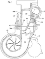
- the Fig. 2 shows a preferred embodiment of the exhaust manifold 6 upstream and near the exhaust gas turbine 8 of the exhaust gas turbocharger 7 arranged in the region or on the connecting flange 6a of the exhaust manifold 6, here specifically at a lower wall portion of the connecting flange 6a of the exhaust manifold 6, via a shaft 13, is pivotally mounted.
- the exhaust gas turbine can in principle also be multi-flow, for example double-flowed.
- the second flood for example, configured accordingly with one respective brake flap 12 for each flood, wherein the brake flaps 12 can then all be controlled independently of one another or else via a common shaft (for example the shaft 13) in common can be controlled or operated.
- brake flap 12 is also designed as a flow, by releasing the full cross section of the exhaust port to the exhaust gas turbine 8 in the open position and in intermediate positions up to full closure the exhaust stream to the turbine wheel (not shown) of the exhaust gas turbine 8 deflects such that accelerated by the cross-sectional constriction exhaust gas flow, the turbine wheel drives the same reinforced the function of a variable turbine geometry or optionally in bumping.
- the brake flap 12 protrudes, as shown in the open state Fig. 2 can be seen, in the fully open position shown here with its free end beyond the connecting flange 6a out, for example, about half its length, in the inflow 8b of the exhaust gas turbine 8 and its connection flange 8a close to the turbine wheel into the positive-acting flow to reinforce.
- the brake flap 12 but also, as shown in the Fig. 2 is shown only very schematically and dashed, part of a, the brake flap 12 having separate unit 28, which is installed between the turbine housing of the exhaust turbine 8 and then adjoining the separate assembly 28 exhaust manifold 6 'and with both the turbine housing the exhaust gas turbine 8 as well as with the exhaust manifold 6 'is firmly connected.
- the at least one brake flap thus forms part of a separate, separately installable unit 28 or component with its own housing. Otherwise, the structure or mode of operation is identical to that or the one or the same as it has already been described above.
- a bracket 14 is further attached, which carries a pneumatic actuator 15 (for example, a piston-cylinder unit) as a controller, by means of which via a piston rod 16 and a lever 17, the brake flap 12 is actuated.
- the actuator 15 can be applied by means of a connected to a pressure medium source valve (not shown), for example by means of a proportional valve or a clock valve, precisely in positions between open and fully closed.
- a pressure medium source valve not shown
- the use of an electric actuator would also be possible in principle.
- an electronic engine control unit 18 is provided as a control and / or regulating device, which are preferably supplied in addition to the usual operating parameters of the internal combustion engine (speed, temperature, etc.) at least one signal B as a motor brake signal and a load signal ⁇ .
- the value of the boost pressure PL in the intake manifold 4 and the value of the exhaust backpressure PA in the exhaust manifold 6 are detected via sensors 19, 20, which are preferably designed as pressure sensors, and fed to the control unit 18 via corresponding signal lines (without reference symbols).
- the sensor 20, preferably a pressure sensor, in the exhaust manifold 6 is functionally arranged upstream of the exhaust gas turbine 8.
- the sensor 20 is not itself arranged directly and directly upstream of the brake flap 12 in the exhaust manifold 6, but is spaced therefrom and disposed away from a GeHouseanformung 8c and connected via a line 21 to the exhaust manifold 6 upstream of the brake flap 12.
- This line 21 is preferably formed here as, with respect to a vertical axis direction, to the sensor 20 sloping line 21.
- the Gepuranformung 8c is of course in the operating condition colder than the region lying upstream of the brake flap 12 of the exhaust manifold 6, in which the line 21 opens.
- the exhaust-gas turbocharger 7 can optionally have a bypass valve 22, with which exhaust gas can be guided past the turbine wheel of the exhaust-gas turbine 8 in order to avoid an excessively high boost pressure PL.
- the bypass valve 22 may be directly integrated into the exhaust gas turbine 8 and is therefore in the illustration according to Fig. 2 not apparent.
- the internal combustion engine 1 may also purely optionally have an exhaust gas recirculation line 23 between the intake system 4 and the exhaust system 3, in which a controllable via the engine control unit 18 exhaust gas recirculation valve 24 is provided.
- the mouth of the exhaust gas recirculation line 23 in the exhaust manifold 6 is as out Fig. 1 the opening of the exhaust gas return line 23 into the intake manifold 4 is preferably carried out downstream of the optional throttle flap 5.
- An engine braking in overrun mode of the motor vehicle is in particular initiated by the signal B and causes a defined closing of the brake flap 12, depending inter alia on the speed of the internal combustion engine and optionally on the request of the desired braking power. Furthermore, depending on the temperature, closing of the exhaust gas recirculation valve 24 may optionally be controlled.
- the closed position of the brake flap 12 is further defined by the boost pressure PL in the intake manifold 4 and the exhaust back pressure PA in the exhaust manifold 6 of the internal combustion engine.
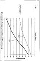
- Fig. 3 to 5 show values measured in corresponding graphics in the case of an exemplary decompression brake and regulated brake flap 12, in each case above the rotational speed n of the internal combustion engine 1 and regarding the achievable specific braking power (FIG. Fig. 3 , Curve 25a), in Fig. 4 the prevailing exhaust back pressure PA (curve 26a) and in Fig. 5 the boost pressure curve PL (curve 27a), in each case in comparison to a conventional arrangement and design of the brake flap 12 downstream of the exhaust gas turbine (curves 25b, 26b, 27b).
- both curves 25a, 26a based on the solution according to the invention each have a strongly increasing gradient.
- Fig. 6 and Fig. 7 in each case a section through the exhaust manifold 6 and the exhaust gas turbine 8 of the exhaust gas turbocharger 7 is shown, with which the operation of the brake flap 12 is explained in more detail.
- the brake flap 12 is shown in its open position 29, in which the brake flap 12 is arranged, for example, in normal operation or in non-engine braking operation. In this open position 29, the brake flap 12 is here, for example, the full or the maximum flow cross-section Q max of an exhaust gas flow channel 30 formed by the exhaust manifold 6 and the exhaust gas turbine 8 free, here also forms the outflow.
- the brake flap 12 is here for example in such a recess 31 of a channel wall 32 of the exhaust gas flow channel 30 that it is substantially flush with the surface immediately adjacent to the recess 31 wall portions 33 of the channel wall 32 connects. In this way, by means of the brake flap 12, a continuous transition between the wall portions 33 of the channel wall 32 is realized, with which a particularly low flow resistance is ensured.
- the depression 31 has here, for example, an exhaust-gas-side region 34 and an exhaust gas-side region 35.
- a closed position 36 of the brake flap 12 in which the brake flap 12 is arranged, for example, in the engine braking operation.
- the brake flap 12 blocks here by way of example the exhaust gas flow channel 30 completely, so that the exhaust gas is backlogged here maximum.
- the brake flap 12 is here for example with a free end portion 37 in a recess 38 on the channel wall 32 a.
- the recess 38 is formed on a wall region 39a of the channel wall 32 arranged opposite to a fixing region 39 of the brake flap 12.
- the recess 38 is here arranged by way of example exhaust manifold side. Alternatively, it would of course also be conceivable that the recess 38 is arranged on the exhaust gas turbine side.
- the recess 38 is formed here so contour-matched to the end portion 37 of the brake flap 12 that the brake flap 12 in the closed position 36 with its end portion 37 in a planar contact with a depression 38 forming recess wall portion 40.
- the exhaust gas in the closed position 36 of the brake flap 12 is stowed particularly effective.
- the recess 38 seen in the exhaust gas flow direction, is arranged downstream of a measuring point 41 of the pressure sensor 20.
- Fig. 7 the brake flap 12 is shown in an intermediate position 42 between the open position 29 and the closed position 36, in which the brake flap 12, for example, also in the engine braking operation is arranged.
- the brake flap 12 releases a flow cross section Q Z which is smaller than the maximum flow cross section Q max .
- the brake flap 42 is arranged in the intermediate position 42 such that the flow cross-section of the exhaust gas flow channel 30 in the exhaust flow direction by means of the brake flap 12 nozzle-like reduced and the flowing past the brake flap 12 exhaust gas flow is accelerated. In this way it is achieved that a turbine wheel 43 of the exhaust gas turbine 8 is also driven in the engine braking operation by the exhaust gas flow, which increases the charge air pressure and finally the engine braking performance.
- the brake flap 12 arranged in the intermediate position 42 releases 0.1% to 20%, particularly preferably 1.3% to 11.1%, of the maximum flow cross section Q max , in order to effectively drive the turbine wheel 43 and simultaneously during engine braking operation to ensure a high exhaust pressure back pressure.
Claims (19)
- Dispositif de frein moteur pour un moteur à combustion interne (1) dans des véhicules automobiles, qui présente un système d'admission (2), un système de gaz d'échappement (3), des soupapes d'échange de gaz du côté du moteur à combustion interne, une turbocompression de gaz d'échappement au moyen d'au moins un turbocompresseur à gaz d'échappement (7) intégré dans le système de gaz d'échappement (3) et dans le système d'admission (2), réalisé à un ou plusieurs flux, ainsi qu'un dispositif de frein moteur, le dispositif de frein moteur présentant un frein à décompression influençant au moins une soupape de sortie des soupapes d'échange de gaz et chaque flux présentant un clapet de frein (12) disposé dans le système de gaz d'échappement, refoulant le gaz d'échappement, et le clapet de frein (12) étant disposé directement en amont et à l'extérieur d'un carter de turbine d'une turbine à gaz d'échappement (8) du turbocompresseur à gaz d'échappement (7), caractérisé en ce que le clapet de frein (12) est réalisé sous forme de clapet de guidage d'écoulement influençant la sollicitation de la turbine à gaz d'échappement (8) par un flux de gaz, lequel clapet de guidage d'écoulement est disposé en mode de frein moteur dans une position intermédiaire (42) entre une position ouverte (29) et une position fermée (36), dans laquelle le clapet de frein (12) libère une section transversale d'écoulement (QZ) réalisée de manière à être inférieure à la section transversale d'écoulement maximale (Qmax) et est disposé de telle sorte que la section transversale d'écoulement du canal d'écoulement de gaz d'échappement (30) diminue en forme de buse dans la direction d'écoulement du gaz d'échappement au moyen du clapet de frein (12) et que le flux de gaz d'échappement s'écoulant devant le clapet de frein (12) soit accéléré, le clapet de frein (12) disposé dans la position intermédiaire (42) libérant une section transversale d'écoulement qui est comprise dans une plage de 0,1 % à 20 % de la section transversale d'écoulement maximale, et le flux de gaz d'échappement s'écoulant devant le clapet de frein (12) constituant le seul flux de gaz d'échappement s'écoulant vers la roue de turbine (43).
- Dispositif de frein moteur selon la revendication 1, caractérisé en ce que la turbine à gaz d'échappement (8) en particulier un carter de turbine de la turbine à gaz d'échappement (8), est accouplée par une liaison fluidique à un collecteur de gaz d'échappement (6') sollicité avec du gaz d'échappement par le biais d'au moins un, et de préférence plusieurs, cylindres du moteur à combustion interne (1), une unité structurelle séparée (28) présentant le clapet de frein (12) étant montée entre la turbine à gaz d'échappement (8) et le collecteur de gaz d'échappement (6'), en particulier entre un carter de turbine de la turbine à gaz d'échappement (8) et le collecteur de gaz d'échappement (6'), et donc directement en amont et à l'extérieur d'un carter de turbine de la turbine à gaz d'échappement (8).
- Dispositif de frein moteur selon la revendication 1, caractérisé en ce que la turbine à gaz d'échappement (8), en particulier un carter de turbine de la turbine à gaz d'échappement (8), est montée directement au niveau d'un collecteur de gaz d'échappement (6) sollicité avec du gaz d'échappement par le biais d'au moins un, de préférence par le biais de plusieurs, cylindres du moteur à combustion interne (1), et en ce que le clapet de frein (12) est disposé dans la région du collecteur de gaz d'échappement (6) et donc directement en amont et à l'extérieur d'un carter de turbine de la turbine à gaz d'échappement (8).
- Dispositif de frein moteur selon la revendication 2 ou 3, caractérisé en ce que le clapet de frein (12) est disposé dans la région d'une bride de raccordement (6a) d'un boîtier de l'unité structurelle séparée (28) ou dans la région d'une bride de raccordement (6a) du collecteur de gaz d'échappement (6), en particulier au niveau d'une région de paroi, du côté de la bride de raccordement, du boîtier de l'unité structurelle séparée (28) ou du collecteur de gaz d'échappement (6), en particulier est disposé de manière à pouvoir pivoter dans la région, ou au niveau, d'une bride de raccordement (6a) du boîtier de l'unité structurelle séparée (28) du collecteur de gaz d'échappement (6) vers la turbine à gaz d'échappement (8) de telle sorte que dans l'état ouvert, il libère la section transversale de gaz d'échappement et que dans l'état fermé, il réduise la section transversale de gaz d'échappement.
- Dispositif de frein moteur selon l'une quelconque des revendications précédentes, caractérisé en ce que le clapet de frein (12), dans une position ouverte, en particulier dans l'état complètement ouvert, pénètre au moins avec une région d'extrémité libre au-delà de la bride de raccordement (6a) dans le canal d'afflux (8b) de la turbine à gaz d'échappement (8).
- Dispositif de frein moteur selon l'une quelconque des revendications précédentes, caractérisé en ce que dans le cas d'une suralimentation à plusieurs étages, en particulier à deux étages, le clapet de frein (12) est disposé, vu dans la direction d'écoulement, en amont d'une première turbine à gaz d'échappement d'un premier turbocompresseur à gaz d'échappement et/ou en ce qu'à chaque flux de la turbine à gaz d'échappement (8) est associé un clapet de frein (12).
- Dispositif de frein moteur selon l'une quelconque des revendications précédentes, caractérisé en ce que le clapet de frein (12), en mode de frein moteur (B), est commandé en fonction de la contre-pression de gaz d'échappement (PA) en amont du clapet de frein (12) et/ou en fonction de la pression de charge (PL) dans le système d'admission (2) du moteur à combustion interne (1) au moyen d'un dispositif de régulation et/ou de commande (18).
- Dispositif de frein moteur selon la revendication 7, caractérisé en ce que pour la détection de la contre-pression de gaz d'échappement (PA), un capteur (20), en particulier un capteur de pression, est disposé en amont du clapet de frein (12) dans le système de gaz d'échappement (3) et/ou en ce que pour détecter la pression de charge (PL), un capteur (19), en particulier un capteur de pression, est disposé en aval d'un compresseur (9) dans la région du collecteur d'admission (19).
- Dispositif de frein moteur selon la revendication 8, caractérisé en ce que le capteur (20) pour détecter la contre-pression de gaz d'échappement (PA) est disposé fonctionnellement en amont du clapet de frein (12) de telle sorte que le capteur (20) soit disposé à distance et de manière éloignée de la région située en amont de celui-ci et soit raccordé à la région située en amont du clapet de frein (12) par le biais d'une conduite (21) débouchant en amont du clapet de frein (12) dans le système de gaz d'échappement (3), et de préférence cette conduite (21) étant réalisée sous forme de conduite (21) descendant vers le capteur par rapport à une direction d'axe vertical.
- Dispositif de frein moteur selon l'une quelconque des revendications précédentes, caractérisé en ce que pour l'actionnement du clapet de frein (12), il est prévu un actionneur électrique commandé par un dispositif de commande et/ou de régulation, en particulier par un appareil électronique de commande de moteur (18), ou en variante il est prévu un dispositif de réglage (15) de préférence sollicité pneumatiquement et une soupape raccordée à celui-ci.
- Dispositif de frein moteur selon la revendication 10, caractérisé en ce qu'au moins un signal de frein (B) amorçant le freinage moteur et/ou un signal de charge (α) et/ou une contre-pression de gaz d'échappement (PA) et/ou une pression de charge (PL) peut ou peuvent être acheminés dans le système d'admission (4) au dispositif de commande et/ou de régulation, en particulier à l'appareil électronique de commande de moteurs (18), et au moins la position du clapet de frein (12) peut ainsi être réglée en fonction d'une puissance de frein moteur exigée.
- Dispositif de frein moteur selon l'une quelconque des revendications précédentes, caractérisé en ce qu'une recirculation de gaz d'échappement depuis le système de gaz d'échappement (3) vers le système d'admission (4), avec une soupape de recirculation de gaz d'échappement (24) commandée de préférence électriquement ou pneumatiquement, est prévue dans une conduite de recirculation des gaz d'échappement (23).
- Dispositif de frein moteur selon l'une quelconque des revendications précédentes, caractérisé en ce qu'un effet de frein à décompression est commandé par la contre-pression de gaz d'échappement (PA) ou en ce qu'un effet de frein à décompression est provoqué par un dispositif superposé à la commande de soupape, de préférence commandé électriquement ou pneumatiquement ou hydrauliquement.
- Dispositif de frein moteur selon l'une quelconque des revendications précédentes, caractérisé en ce que le clapet de frein (12), dans sa position ouverte dans laquelle il libère toute la section transversale de l'ouverture de sortie, est disposé au moins en partie en affleurement avec la surface d'une paroi de canal (32) d'un canal d'écoulement de gaz d'échappement (30) constituant l'ouverture de sortie, de préférence le clapet de frein (12) est reçu et/ou s'insère dans un renfoncement (31) du côté de la paroi et se raccorde essentiellement en affleurement avec la surface des régions de paroi (33) de la paroi de canal (32), immédiatement adjacente au renfoncement (31), d'un canal d'écoulement (30) de gaz d'échappement constituant l'ouverture de sortie.
- Dispositif de frein moteur selon l'une quelconque des revendications précédentes, caractérisé en ce que le clapet de frein (12), disposé dans la position intermédiaire, libère une section transversale d'écoulement qui est située dans une plage de 1 % à 12 %, de préférence de 1,3 % à 11, 1 % de la section transversale d'écoulement maximale.
- Procédé pour faire fonctionner un dispositif de frein moteur pour un moteur à combustion interne (1) dans des véhicules automobiles, le dispositif de frein moteur présentant un système d'admission (2), un système de gaz d'échappement (3), des soupapes d'échange de gaz du côté du moteur à combustion interne, une turbocompression de gaz d'échappement au moyen d'au moins un turbocompresseur à gaz d'échappement (7) intégré dans le système de gaz d'échappement (3) et dans le système d'admission (2), réalisé à un ou plusieurs flux, ainsi qu'un dispositif de frein moteur, le dispositif de frein moteur présentant un frein à décompression influençant au moins une soupape de sortie des soupapes d'échanges de gaz et chaque flux présentant un clapet de frein (12) disposé dans le système de gaz d'échappement, refoulant le gaz d'échappement, et le clapet de frein (12) étant disposé directement en amont et à l'extérieur d'un carter de turbine d'une turbine à gaz d'échappement (8) du turbocompresseur à gaz d'échappement (7), caractérisé en ce que le clapet de frein (12) est réalisé sous forme de clapet de guidage d'écoulement au moyen duquel la turbine à gaz d'échappement (8) est sollicitée en fonction de la position du clapet de frein (12) avec un flux de gaz défini, le clapet de frein (12), en mode de frein moteur, étant disposé dans une position intermédiaire (42) entre une position ouverte (29) et une position fermée (36), dans laquelle le clapet de frein (12) libère une section transversale d'écoulement (QZ) réalisée de manière à être inférieure à la section transversale d'écoulement maximale (Qmax) et est disposé de telle sorte que la section transversale d'écoulement du canal d'écoulement de gaz d'échappement (30) diminue en forme de buse dans la direction d'écoulement du gaz d'échappement au moyen du clapet de frein (12) et que le flux de gaz d'échappement s'écoulant devant le clapet de frein (12) soit accéléré, le clapet de frein (12) disposé dans la position intermédiaire (42) libérant une section transversale d'écoulement qui est comprise dans une plage de 0,1 % à 20 % de la section transversale d'écoulement maximale, et le flux de gaz d'échappement s'écoulant devant le clapet de frein (12) constituant le seul flux de gaz d'échappement s'écoulant vers la roue de turbine (43).
- Procédé selon la revendication 16, caractérisé en ce que le clapet de frein (12) disposé dans la position intermédiaire libère une section transversale d'écoulement qui est située dans une plage de 1 % à 12 %, de préférence de 1,3 % à 11,1 % de la section transversale d'écoulement maximale.
- Procédé selon la revendication 16 ou 17, caractérisé en ce que le clapet de frein (12), lorsqu'il n'est pas en mode de frein moteur, libère une première section transversale d'écoulement, de préférence la section transversale d'écoulement maximale, et en ce que le clapet de frein (12), en mode de frein moteur, libère une deuxième section transversale d'écoulement réalisée de manière à être inférieure à la première section transversale d'écoulement.
- Véhicule comprenant un dispositif de frein moteur selon l'une quelconque des revendications 1 à 15.
Applications Claiming Priority (1)
| Application Number | Priority Date | Filing Date | Title |
|---|---|---|---|
| ATA908/2014A AT516513B1 (de) | 2014-12-15 | 2014-12-15 | Motorbremsvorrichtung für eine Brennkraftmaschine sowie Verfahren zum Betreiben einer Motorbremsvorrichtung |
Publications (2)
| Publication Number | Publication Date |
|---|---|
| EP3034844A1 EP3034844A1 (fr) | 2016-06-22 |
| EP3034844B1 true EP3034844B1 (fr) | 2019-05-15 |
Family
ID=54849744
Family Applications (1)
| Application Number | Title | Priority Date | Filing Date |
|---|---|---|---|
| EP15003532.7A Revoked EP3034844B1 (fr) | 2014-12-15 | 2015-12-11 | Dispositif de freinage pour un moteur à combustion interne et procédé de fonctionnement d'un dispositif de freinage |
Country Status (6)
| Country | Link |
|---|---|
| US (1) | US10267238B2 (fr) |
| EP (1) | EP3034844B1 (fr) |
| CN (1) | CN105822379B (fr) |
| AT (1) | AT516513B1 (fr) |
| BR (1) | BR102015031170B1 (fr) |
| RU (1) | RU2709893C2 (fr) |
Families Citing this family (9)
| Publication number | Priority date | Publication date | Assignee | Title |
|---|---|---|---|---|
| RU2706246C2 (ru) * | 2016-11-18 | 2019-11-15 | Федеральное Государственное Казенное Военное Образовательное Учреждение Высшего Образования Военный Учебно-Научный Центр Сухопутных Войск "Общевойсковая Академия Вооруженных Сил Российской Федерации" | Устройство пуска бензинового двигателя внутреннего сгорания автомобиля |
| CN106438058A (zh) * | 2016-12-07 | 2017-02-22 | 东风商用车有限公司 | 一种带排气制动碟阀的发动机排气管 |
| DE102017115599A1 (de) * | 2017-07-12 | 2019-01-17 | Man Truck & Bus Ag | Brennkraftmaschine, insbesondere als Antriebsmotor für ein Fahrzeug |
| CN108150315B (zh) * | 2017-12-29 | 2021-05-18 | 潍柴动力股份有限公司 | Egr排气处理装置及汽车 |
| AT521954B1 (de) * | 2019-01-31 | 2020-07-15 | MAN TRUCK & BUS OESTERREICH GesmbH | Vorrichtung zur Abgasführung für eine Brennkraftmaschine |
| CN109882298B (zh) * | 2019-03-19 | 2021-08-20 | 潍柴动力股份有限公司 | 一种调节装置及发动机 |
| CN113047966B (zh) * | 2021-03-04 | 2022-07-12 | 广西玉柴机器股份有限公司 | 一种可调发动机缸内制动功率的方法、系统及相关装置 |
| US11608775B1 (en) | 2022-07-26 | 2023-03-21 | Garrett Transportation I Inc. | Control method for variable turbine nozzle of turbocharger during engine braking |
| CN115355071B (zh) * | 2022-10-24 | 2023-02-10 | 龙口中宇热管理系统科技有限公司 | 一种发动机缸内制动机构及方法 |
Citations (10)
| Publication number | Priority date | Publication date | Assignee | Title |
|---|---|---|---|---|
| DE2648676A1 (de) | 1976-03-11 | 1977-09-22 | Josef V Illichmann | Auspuffbremse |
| US6155049A (en) | 1998-03-03 | 2000-12-05 | Daimlerchrysler Ag | Method of controlling the charge air mass flow of a supercharged internal combustion engine |
| US20030178002A1 (en) | 2003-02-27 | 2003-09-25 | Israel Mark A. | Apparatus and method to operate an engine exhaust brake together with an exhaust gas recirculation system |
| US20060230759A1 (en) | 2005-04-13 | 2006-10-19 | Semrau H A | Variable geometry turbocharger |
| US20070137200A1 (en) | 2005-12-20 | 2007-06-21 | Franz Rammer | Device for increasing the braking power of a multi-cylinder internal combustion engine of a vehicle during an engine braking operation |
| WO2010151391A1 (fr) | 2009-06-25 | 2010-12-29 | International Engine Intellectual Property Company, Llc | Soupape de frein pour freinage moteur |
| US20120017869A1 (en) | 2010-07-26 | 2012-01-26 | Man Nutzfahrzeuge Osterreich Ag | Method and device for engine braking |
| US20120017868A1 (en) | 2010-07-26 | 2012-01-26 | Man Nutzfahrzeuge Oesterreich Ag | Method and device for engine braking |
| EP2607650A2 (fr) | 2011-12-23 | 2013-06-26 | MAN Truck & Bus Österreich AG | Dispositif d'étranglement d'un turbocompresseur |
| EP2679787A1 (fr) | 2012-06-28 | 2014-01-01 | MAN Truck & Bus AG | Procédé et dispositif destinés à la commande d'un volet de freinage |
Family Cites Families (24)
| Publication number | Priority date | Publication date | Assignee | Title |
|---|---|---|---|---|
| US3423926A (en) * | 1966-08-31 | 1969-01-28 | Garrett Corp | Turbocharger control arrangement |
| AT279275B (de) * | 1968-08-07 | 1970-02-25 | Maschf Augsburg Nuernberg Ag | Abgasdrossel für Auspuffbremsen an aufgeladenen Verbrennungsmotoren |
| DE3922884A1 (de) | 1989-07-12 | 1991-01-24 | Man Nutzfahrzeuge Ag | Motorbremse fuer luftverdichtende brennkraftmaschinen |
| DE19540060A1 (de) * | 1995-10-27 | 1997-04-30 | Daimler Benz Ag | Motorbremsvorrichtung |
| AT411545B (de) * | 2001-05-14 | 2004-02-25 | Man Steyr Ag | Brennkraftmaschine in einem fahrzeug mit einer motorbremsvorrichtung und einer abgasrückführeinrichtung |
| ITTO20010615A1 (it) * | 2001-06-26 | 2002-12-26 | Iveco Motorenforschung Ag | Unita' motore endotermico-turbocompressore per un autoveicolo, in particolare per un veicolo industriale, con controllo della potenza della |
| DE10239110B4 (de) * | 2002-08-27 | 2004-08-19 | Caterpillar Motoren Gmbh & Co. Kg | Aufladesystem für eine Brennkraftmaschine |
| EP1710415A1 (fr) * | 2005-04-04 | 2006-10-11 | ABB Turbo Systems AG | Suralimentation multi-étagée |
| BRPI0520619B8 (pt) * | 2005-09-15 | 2020-01-28 | Volvo Lastvagnar Ab | método para manter calor em um sistema de pós tratamento de exaustão |
| DE102006058102B4 (de) * | 2006-12-09 | 2020-08-06 | Daimler Ag | Brennkraftmaschine mit Abgasturbolader |
| GB0717212D0 (en) * | 2007-09-05 | 2007-10-17 | Cummins Turbo Tech Ltd | Multi-stage turbocharger system |
| DE102008008723B4 (de) * | 2008-02-12 | 2013-07-11 | Knorr-Bremse Systeme für Nutzfahrzeuge GmbH | Verfahren und Vorrichtung zum Erzeugen von Druckluft und zum Einblasen derselben bei einer Verbrennungskraftmaschine |
| DE102008008721A1 (de) * | 2008-02-12 | 2009-08-20 | Knorr-Bremse Systeme für Nutzfahrzeuge GmbH | Verfahren und Vorrichtung zum Versorgen eines Kompressors mit Druckluft bei einer Verbrennungskraftmaschine |
| DE102008061412A1 (de) | 2008-07-11 | 2010-01-14 | Man Nutzfahrzeuge Ag | Hydraulischer Ventil- und EVB-Spielausgleich |
| DE102009019437A1 (de) * | 2009-04-29 | 2010-11-04 | Man Nutzfahrzeuge Ag | Vorrichtung zur Steigerung der Bremsleistung einer mehrzylindrigen Brennkraftmaschine eines Fahrzeugs während des Motorbremsbetriebes |
| CN102472178A (zh) * | 2009-06-29 | 2012-05-23 | 万国引擎知识产权有限责任公司 | 使用制动阀和部分进气流涡轮机涡轮增压器的发动机制动器 |
| JP2012097604A (ja) * | 2010-10-29 | 2012-05-24 | Isuzu Motors Ltd | 内燃機関の排気ブレーキ制御方法及び装置 |
| DE102011115296A1 (de) * | 2011-09-29 | 2013-04-04 | Mtu Friedrichshafen Gmbh | Zweistufige Aufladevorrichtung |
| AT512567B1 (de) | 2012-03-01 | 2014-03-15 | Man Truck & Bus Oesterreich Ag | Funktionsmodul mit einem Abgasturbolader und einem Abgaskrümmer |
| AT512910B1 (de) * | 2012-04-02 | 2013-12-15 | Man Truck & Bus Oesterreich Ag | Verfahren und Vorrichtung zum Steuern des Motorbremsbetriebs an Brennkraftmaschinen |
| ES2537702T3 (es) * | 2012-06-07 | 2015-06-11 | Daf Trucks N.V. | Control de un freno de liberación de compresión |
| US20140214308A1 (en) * | 2013-01-29 | 2014-07-31 | Cummins Ip, Inc. | Apparatus, system and method for increasing braking power |
| DE102013011587A1 (de) * | 2013-07-10 | 2015-01-15 | Daimler Ag | Verbrennungskraftmaschine für einen Kraftwagen sowie Verfahren zum Betreiben einer solchen Verbrennungskraftmaschine |
| US10570834B2 (en) * | 2016-10-27 | 2020-02-25 | Cummins Inc. | Supercharging for improved engine braking and transient performance |
-
2014
- 2014-12-15 AT ATA908/2014A patent/AT516513B1/de active
-
2015
- 2015-12-11 CN CN201511036258.8A patent/CN105822379B/zh active Active
- 2015-12-11 BR BR102015031170-2A patent/BR102015031170B1/pt active IP Right Grant
- 2015-12-11 US US14/966,553 patent/US10267238B2/en active Active
- 2015-12-11 RU RU2015153191A patent/RU2709893C2/ru active
- 2015-12-11 EP EP15003532.7A patent/EP3034844B1/fr not_active Revoked
Patent Citations (10)
| Publication number | Priority date | Publication date | Assignee | Title |
|---|---|---|---|---|
| DE2648676A1 (de) | 1976-03-11 | 1977-09-22 | Josef V Illichmann | Auspuffbremse |
| US6155049A (en) | 1998-03-03 | 2000-12-05 | Daimlerchrysler Ag | Method of controlling the charge air mass flow of a supercharged internal combustion engine |
| US20030178002A1 (en) | 2003-02-27 | 2003-09-25 | Israel Mark A. | Apparatus and method to operate an engine exhaust brake together with an exhaust gas recirculation system |
| US20060230759A1 (en) | 2005-04-13 | 2006-10-19 | Semrau H A | Variable geometry turbocharger |
| US20070137200A1 (en) | 2005-12-20 | 2007-06-21 | Franz Rammer | Device for increasing the braking power of a multi-cylinder internal combustion engine of a vehicle during an engine braking operation |
| WO2010151391A1 (fr) | 2009-06-25 | 2010-12-29 | International Engine Intellectual Property Company, Llc | Soupape de frein pour freinage moteur |
| US20120017869A1 (en) | 2010-07-26 | 2012-01-26 | Man Nutzfahrzeuge Osterreich Ag | Method and device for engine braking |
| US20120017868A1 (en) | 2010-07-26 | 2012-01-26 | Man Nutzfahrzeuge Oesterreich Ag | Method and device for engine braking |
| EP2607650A2 (fr) | 2011-12-23 | 2013-06-26 | MAN Truck & Bus Österreich AG | Dispositif d'étranglement d'un turbocompresseur |
| EP2679787A1 (fr) | 2012-06-28 | 2014-01-01 | MAN Truck & Bus AG | Procédé et dispositif destinés à la commande d'un volet de freinage |
Non-Patent Citations (2)
| Title |
|---|
| "New Holset Turbochargers for Small Diesel", THE LATEST TURBOCHARGER NEWS HTI, 2011, pages 1 - 10, XP055688650 |
| "Smart thinking behind latest Holset VGTTM actuators", THE LATEST TURBOCHARGER NEWS, 2008, pages 1 - 14, XP055688658 |
Also Published As
| Publication number | Publication date |
|---|---|
| RU2015153191A (ru) | 2017-06-20 |
| RU2709893C2 (ru) | 2019-12-23 |
| BR102015031170A2 (pt) | 2016-09-06 |
| BR102015031170B1 (pt) | 2022-09-13 |
| US20160169128A1 (en) | 2016-06-16 |
| AT516513B1 (de) | 2016-06-15 |
| CN105822379A (zh) | 2016-08-03 |
| US10267238B2 (en) | 2019-04-23 |
| RU2015153191A3 (fr) | 2019-06-20 |
| AT516513A4 (de) | 2016-06-15 |
| EP3034844A1 (fr) | 2016-06-22 |
| CN105822379B (zh) | 2019-12-17 |
Similar Documents
| Publication | Publication Date | Title |
|---|---|---|
| EP3034844B1 (fr) | Dispositif de freinage pour un moteur à combustion interne et procédé de fonctionnement d'un dispositif de freinage | |
| EP3034843B1 (fr) | Procédé de commande d'un dispositif de frein moteur et dispositif de frein moteur | |
| EP2412954B1 (fr) | Procédé de freinage moteur | |
| EP2412955B1 (fr) | Procédé de freinage moteur | |
| EP1809876B1 (fr) | Procede et dispositif pour commander ou reguler une pression d'admission d'un moteur a combustion interne dote d'un compresseur | |
| DE102008048681B4 (de) | Brennkraftmaschine mit zwei Ladern und Verfahren zum Betreiben derselben | |
| EP2679787B1 (fr) | Procédé et dispositif destinés à la commande d'un volet de freinage | |
| DE102010004657B4 (de) | Frischgasversorgungsvorrichtung für eine Verbrennungsmaschine und Verfahren zum Betrieb einer solchen Frischgasversorgungsvorrichtung | |
| DE102004056894A1 (de) | Verfahren und Vorrichtung zur Regelung des Ladedrucks einer Brennkraftmaschine | |
| DE112015001521T5 (de) | Verfahren zur Steuerung eines turboaufgeladenen Motors und Steuervorrichtung eines turboaufgeladenen Motors | |
| WO2006037564A1 (fr) | Procede et dispositif d'augmentation du couple d'un moteur alternatif a combustion interne, en particulier d'un moteur diesel | |
| DE19841330A1 (de) | Steuerung einer aufgeladenen Otto-Brennkraftmaschine | |
| EP2634393B1 (fr) | Module de fonctionnement doté d'une turbosoufflante de gaz d'échappement et d'un collecteur de gaz d'échappement | |
| EP2246543A1 (fr) | Culasse comprenant deux collecteurs d'échappement et procédé destiné au fonctionnement d'un moteur à combustion interne comprenant une telle culasse | |
| EP1762716B1 (fr) | Frein d'échappement avec une conduite de bypass | |
| DE4024572C2 (de) | Registeraufladung für Brennkraftmaschinen in Nutzfahrzeugen | |
| WO2008017440A1 (fr) | Moteur à combustion interne | |
| DE10133669A1 (de) | Abgasturbolader in einer Brennkraftmaschine | |
| DE102012200014A1 (de) | Mehrzylinder-Brennkraftmaschine undVerfahren zum Betreiben einer derartigen Mehrzylinder-Brennkraftmaschine | |
| DE102010029109A1 (de) | Vorrichtung und Verfahren zum Betreiben einer Antriebsvorrichtung | |
| EP2602449B1 (fr) | Moteur à combustion interne avec turbosoufflante de gaz d'échappement et refroidisseur de gaz d'échappement ainsi que procédé de commande/réglage de la température de fonctionnement de la turbosoufflante de gaz d'échappement | |
| EP2405111A1 (fr) | Moteur à combustion interne doté d'un dispositif de chargement pour comprimer un gaz de fonctionnement | |
| DE102015218335B4 (de) | Turbine für einen Abgasturbolader | |
| WO2005071243A1 (fr) | Compresseur installe dans la tubulure d'admission d'un moteur a combustion interne | |
| DE202005022134U1 (de) | Bremsklappe mit Bypass |
Legal Events
| Date | Code | Title | Description |
|---|---|---|---|
| PUAI | Public reference made under article 153(3) epc to a published international application that has entered the european phase |
Free format text: ORIGINAL CODE: 0009012 |
|
| AK | Designated contracting states |
Kind code of ref document: A1 Designated state(s): AL AT BE BG CH CY CZ DE DK EE ES FI FR GB GR HR HU IE IS IT LI LT LU LV MC MK MT NL NO PL PT RO RS SE SI SK SM TR |
|
| AX | Request for extension of the european patent |
Extension state: BA ME |
|
| STAA | Information on the status of an ep patent application or granted ep patent |
Free format text: STATUS: REQUEST FOR EXAMINATION WAS MADE |
|
| 17P | Request for examination filed |
Effective date: 20161221 |
|
| RBV | Designated contracting states (corrected) |
Designated state(s): AL AT BE BG CH CY CZ DE DK EE ES FI FR GB GR HR HU IE IS IT LI LT LU LV MC MK MT NL NO PL PT RO RS SE SI SK SM TR |
|
| STAA | Information on the status of an ep patent application or granted ep patent |
Free format text: STATUS: EXAMINATION IS IN PROGRESS |
|
| 17Q | First examination report despatched |
Effective date: 20170517 |
|
| GRAP | Despatch of communication of intention to grant a patent |
Free format text: ORIGINAL CODE: EPIDOSNIGR1 |
|
| STAA | Information on the status of an ep patent application or granted ep patent |
Free format text: STATUS: GRANT OF PATENT IS INTENDED |
|
| INTG | Intention to grant announced |
Effective date: 20171215 |
|
| GRAJ | Information related to disapproval of communication of intention to grant by the applicant or resumption of examination proceedings by the epo deleted |
Free format text: ORIGINAL CODE: EPIDOSDIGR1 |
|
| STAA | Information on the status of an ep patent application or granted ep patent |
Free format text: STATUS: EXAMINATION IS IN PROGRESS |
|
| INTC | Intention to grant announced (deleted) | ||
| GRAP | Despatch of communication of intention to grant a patent |
Free format text: ORIGINAL CODE: EPIDOSNIGR1 |
|
| STAA | Information on the status of an ep patent application or granted ep patent |
Free format text: STATUS: GRANT OF PATENT IS INTENDED |
|
| INTG | Intention to grant announced |
Effective date: 20181204 |
|
| GRAS | Grant fee paid |
Free format text: ORIGINAL CODE: EPIDOSNIGR3 |
|
| GRAA | (expected) grant |
Free format text: ORIGINAL CODE: 0009210 |
|
| STAA | Information on the status of an ep patent application or granted ep patent |
Free format text: STATUS: THE PATENT HAS BEEN GRANTED |
|
| AK | Designated contracting states |
Kind code of ref document: B1 Designated state(s): AL AT BE BG CH CY CZ DE DK EE ES FI FR GB GR HR HU IE IS IT LI LT LU LV MC MK MT NL NO PL PT RO RS SE SI SK SM TR |
|
| REG | Reference to a national code |
Ref country code: CH Ref legal event code: EP |
|
| REG | Reference to a national code |
Ref country code: DE Ref legal event code: R096 Ref document number: 502015009036 Country of ref document: DE |
|
| REG | Reference to a national code |
Ref country code: IE Ref legal event code: FG4D Free format text: LANGUAGE OF EP DOCUMENT: GERMAN |
|
| REG | Reference to a national code |
Ref country code: NL Ref legal event code: FP |
|
| REG | Reference to a national code |
Ref country code: SE Ref legal event code: TRGR |
|
| REG | Reference to a national code |
Ref country code: LT Ref legal event code: MG4D |
|
| PG25 | Lapsed in a contracting state [announced via postgrant information from national office to epo] |
Ref country code: NO Free format text: LAPSE BECAUSE OF FAILURE TO SUBMIT A TRANSLATION OF THE DESCRIPTION OR TO PAY THE FEE WITHIN THE PRESCRIBED TIME-LIMIT Effective date: 20190815 Ref country code: HR Free format text: LAPSE BECAUSE OF FAILURE TO SUBMIT A TRANSLATION OF THE DESCRIPTION OR TO PAY THE FEE WITHIN THE PRESCRIBED TIME-LIMIT Effective date: 20190515 Ref country code: FI Free format text: LAPSE BECAUSE OF FAILURE TO SUBMIT A TRANSLATION OF THE DESCRIPTION OR TO PAY THE FEE WITHIN THE PRESCRIBED TIME-LIMIT Effective date: 20190515 Ref country code: AL Free format text: LAPSE BECAUSE OF FAILURE TO SUBMIT A TRANSLATION OF THE DESCRIPTION OR TO PAY THE FEE WITHIN THE PRESCRIBED TIME-LIMIT Effective date: 20190515 Ref country code: PT Free format text: LAPSE BECAUSE OF FAILURE TO SUBMIT A TRANSLATION OF THE DESCRIPTION OR TO PAY THE FEE WITHIN THE PRESCRIBED TIME-LIMIT Effective date: 20190915 Ref country code: LT Free format text: LAPSE BECAUSE OF FAILURE TO SUBMIT A TRANSLATION OF THE DESCRIPTION OR TO PAY THE FEE WITHIN THE PRESCRIBED TIME-LIMIT Effective date: 20190515 Ref country code: ES Free format text: LAPSE BECAUSE OF FAILURE TO SUBMIT A TRANSLATION OF THE DESCRIPTION OR TO PAY THE FEE WITHIN THE PRESCRIBED TIME-LIMIT Effective date: 20190515 |
|
| PG25 | Lapsed in a contracting state [announced via postgrant information from national office to epo] |
Ref country code: BG Free format text: LAPSE BECAUSE OF FAILURE TO SUBMIT A TRANSLATION OF THE DESCRIPTION OR TO PAY THE FEE WITHIN THE PRESCRIBED TIME-LIMIT Effective date: 20190815 Ref country code: RS Free format text: LAPSE BECAUSE OF FAILURE TO SUBMIT A TRANSLATION OF THE DESCRIPTION OR TO PAY THE FEE WITHIN THE PRESCRIBED TIME-LIMIT Effective date: 20190515 Ref country code: LV Free format text: LAPSE BECAUSE OF FAILURE TO SUBMIT A TRANSLATION OF THE DESCRIPTION OR TO PAY THE FEE WITHIN THE PRESCRIBED TIME-LIMIT Effective date: 20190515 Ref country code: GR Free format text: LAPSE BECAUSE OF FAILURE TO SUBMIT A TRANSLATION OF THE DESCRIPTION OR TO PAY THE FEE WITHIN THE PRESCRIBED TIME-LIMIT Effective date: 20190816 |
|
| PG25 | Lapsed in a contracting state [announced via postgrant information from national office to epo] |
Ref country code: SK Free format text: LAPSE BECAUSE OF FAILURE TO SUBMIT A TRANSLATION OF THE DESCRIPTION OR TO PAY THE FEE WITHIN THE PRESCRIBED TIME-LIMIT Effective date: 20190515 Ref country code: CZ Free format text: LAPSE BECAUSE OF FAILURE TO SUBMIT A TRANSLATION OF THE DESCRIPTION OR TO PAY THE FEE WITHIN THE PRESCRIBED TIME-LIMIT Effective date: 20190515 Ref country code: RO Free format text: LAPSE BECAUSE OF FAILURE TO SUBMIT A TRANSLATION OF THE DESCRIPTION OR TO PAY THE FEE WITHIN THE PRESCRIBED TIME-LIMIT Effective date: 20190515 Ref country code: DK Free format text: LAPSE BECAUSE OF FAILURE TO SUBMIT A TRANSLATION OF THE DESCRIPTION OR TO PAY THE FEE WITHIN THE PRESCRIBED TIME-LIMIT Effective date: 20190515 Ref country code: EE Free format text: LAPSE BECAUSE OF FAILURE TO SUBMIT A TRANSLATION OF THE DESCRIPTION OR TO PAY THE FEE WITHIN THE PRESCRIBED TIME-LIMIT Effective date: 20190515 |
|
| REG | Reference to a national code |
Ref country code: DE Ref legal event code: R026 Ref document number: 502015009036 Country of ref document: DE |
|
| PLBI | Opposition filed |
Free format text: ORIGINAL CODE: 0009260 |
|
| PLBI | Opposition filed |
Free format text: ORIGINAL CODE: 0009260 |
|
| PLAX | Notice of opposition and request to file observation + time limit sent |
Free format text: ORIGINAL CODE: EPIDOSNOBS2 |
|
| PG25 | Lapsed in a contracting state [announced via postgrant information from national office to epo] |
Ref country code: SM Free format text: LAPSE BECAUSE OF FAILURE TO SUBMIT A TRANSLATION OF THE DESCRIPTION OR TO PAY THE FEE WITHIN THE PRESCRIBED TIME-LIMIT Effective date: 20190515 |
|
| 26 | Opposition filed |
Opponent name: VOLVO TRUCK CORPORATION Effective date: 20200204 |
|
| 26 | Opposition filed |
Opponent name: DAF TRUCKS N.V. OPERATIONS Effective date: 20200214 |
|
| PG25 | Lapsed in a contracting state [announced via postgrant information from national office to epo] |
Ref country code: TR Free format text: LAPSE BECAUSE OF FAILURE TO SUBMIT A TRANSLATION OF THE DESCRIPTION OR TO PAY THE FEE WITHIN THE PRESCRIBED TIME-LIMIT Effective date: 20190515 |
|
| PG25 | Lapsed in a contracting state [announced via postgrant information from national office to epo] |
Ref country code: PL Free format text: LAPSE BECAUSE OF FAILURE TO SUBMIT A TRANSLATION OF THE DESCRIPTION OR TO PAY THE FEE WITHIN THE PRESCRIBED TIME-LIMIT Effective date: 20190515 |
|
| PG25 | Lapsed in a contracting state [announced via postgrant information from national office to epo] |
Ref country code: SI Free format text: LAPSE BECAUSE OF FAILURE TO SUBMIT A TRANSLATION OF THE DESCRIPTION OR TO PAY THE FEE WITHIN THE PRESCRIBED TIME-LIMIT Effective date: 20190515 |
|
| PLAF | Information modified related to communication of a notice of opposition and request to file observations + time limit |
Free format text: ORIGINAL CODE: EPIDOSCOBS2 |
|
| REG | Reference to a national code |
Ref country code: CH Ref legal event code: PL |
|
| REG | Reference to a national code |
Ref country code: BE Ref legal event code: MM Effective date: 20191231 |
|
| PG25 | Lapsed in a contracting state [announced via postgrant information from national office to epo] |
Ref country code: MC Free format text: LAPSE BECAUSE OF FAILURE TO SUBMIT A TRANSLATION OF THE DESCRIPTION OR TO PAY THE FEE WITHIN THE PRESCRIBED TIME-LIMIT Effective date: 20190515 |
|
| GBPC | Gb: european patent ceased through non-payment of renewal fee |
Effective date: 20191211 |
|
| PLBB | Reply of patent proprietor to notice(s) of opposition received |
Free format text: ORIGINAL CODE: EPIDOSNOBS3 |
|
| PG25 | Lapsed in a contracting state [announced via postgrant information from national office to epo] |
Ref country code: IE Free format text: LAPSE BECAUSE OF NON-PAYMENT OF DUE FEES Effective date: 20191211 Ref country code: GB Free format text: LAPSE BECAUSE OF NON-PAYMENT OF DUE FEES Effective date: 20191211 Ref country code: LU Free format text: LAPSE BECAUSE OF NON-PAYMENT OF DUE FEES Effective date: 20191211 |
|
| PG25 | Lapsed in a contracting state [announced via postgrant information from national office to epo] |
Ref country code: LI Free format text: LAPSE BECAUSE OF NON-PAYMENT OF DUE FEES Effective date: 20191231 Ref country code: CH Free format text: LAPSE BECAUSE OF NON-PAYMENT OF DUE FEES Effective date: 20191231 Ref country code: BE Free format text: LAPSE BECAUSE OF NON-PAYMENT OF DUE FEES Effective date: 20191231 |
|
| PLAB | Opposition data, opponent's data or that of the opponent's representative modified |
Free format text: ORIGINAL CODE: 0009299OPPO |
|
| PG25 | Lapsed in a contracting state [announced via postgrant information from national office to epo] |
Ref country code: CY Free format text: LAPSE BECAUSE OF FAILURE TO SUBMIT A TRANSLATION OF THE DESCRIPTION OR TO PAY THE FEE WITHIN THE PRESCRIBED TIME-LIMIT Effective date: 20190515 |
|
| R26 | Opposition filed (corrected) |
Opponent name: VOLVO TRUCK CORPORATION Effective date: 20200204 |
|
| PG25 | Lapsed in a contracting state [announced via postgrant information from national office to epo] |
Ref country code: IS Free format text: LAPSE BECAUSE OF FAILURE TO SUBMIT A TRANSLATION OF THE DESCRIPTION OR TO PAY THE FEE WITHIN THE PRESCRIBED TIME-LIMIT Effective date: 20190915 |
|
| PG25 | Lapsed in a contracting state [announced via postgrant information from national office to epo] |
Ref country code: HU Free format text: LAPSE BECAUSE OF FAILURE TO SUBMIT A TRANSLATION OF THE DESCRIPTION OR TO PAY THE FEE WITHIN THE PRESCRIBED TIME-LIMIT; INVALID AB INITIO Effective date: 20151211 Ref country code: MT Free format text: LAPSE BECAUSE OF FAILURE TO SUBMIT A TRANSLATION OF THE DESCRIPTION OR TO PAY THE FEE WITHIN THE PRESCRIBED TIME-LIMIT Effective date: 20190515 |
|
| REG | Reference to a national code |
Ref country code: DE Ref legal event code: R081 Ref document number: 502015009036 Country of ref document: DE Owner name: MAN TRUCK & BUS SE, DE Free format text: FORMER OWNER: MAN TRUCK & BUS OESTERREICH AG, STEYR, AT |
|
| RAP2 | Party data changed (patent owner data changed or rights of a patent transferred) |
Owner name: MAN TRUCK & BUS SE |
|
| APAH | Appeal reference modified |
Free format text: ORIGINAL CODE: EPIDOSCREFNO |
|
| APBM | Appeal reference recorded |
Free format text: ORIGINAL CODE: EPIDOSNREFNO |
|
| APBP | Date of receipt of notice of appeal recorded |
Free format text: ORIGINAL CODE: EPIDOSNNOA2O |
|
| APBM | Appeal reference recorded |
Free format text: ORIGINAL CODE: EPIDOSNREFNO |
|
| APBP | Date of receipt of notice of appeal recorded |
Free format text: ORIGINAL CODE: EPIDOSNNOA2O |
|
| APBM | Appeal reference recorded |
Free format text: ORIGINAL CODE: EPIDOSNREFNO |
|
| APBP | Date of receipt of notice of appeal recorded |
Free format text: ORIGINAL CODE: EPIDOSNNOA2O |
|
| REG | Reference to a national code |
Ref country code: AT Ref legal event code: MM01 Ref document number: 1133709 Country of ref document: AT Kind code of ref document: T Effective date: 20201211 |
|
| APBQ | Date of receipt of statement of grounds of appeal recorded |
Free format text: ORIGINAL CODE: EPIDOSNNOA3O |
|
| APBQ | Date of receipt of statement of grounds of appeal recorded |
Free format text: ORIGINAL CODE: EPIDOSNNOA3O |
|
| APBQ | Date of receipt of statement of grounds of appeal recorded |
Free format text: ORIGINAL CODE: EPIDOSNNOA3O |
|
| PG25 | Lapsed in a contracting state [announced via postgrant information from national office to epo] |
Ref country code: AT Free format text: LAPSE BECAUSE OF NON-PAYMENT OF DUE FEES Effective date: 20201211 |
|
| PG25 | Lapsed in a contracting state [announced via postgrant information from national office to epo] |
Ref country code: MK Free format text: LAPSE BECAUSE OF FAILURE TO SUBMIT A TRANSLATION OF THE DESCRIPTION OR TO PAY THE FEE WITHIN THE PRESCRIBED TIME-LIMIT Effective date: 20190515 |
|
| PGFP | Annual fee paid to national office [announced via postgrant information from national office to epo] |
Ref country code: DE Payment date: 20221227 Year of fee payment: 8 |
|
| PLBP | Opposition withdrawn |
Free format text: ORIGINAL CODE: 0009264 |
|
| REG | Reference to a national code |
Ref country code: NL Ref legal event code: PD Owner name: MAN TRUCK & BUS OESTERREICH GESMBH; AT Free format text: DETAILS ASSIGNMENT: CHANGE OF OWNER(S), ASSIGNMENT; FORMER OWNER NAME: MAN TRUCK & BUS OESTERREICH GESMBH Effective date: 20231031 |
|
| REG | Reference to a national code |
Ref country code: DE Ref legal event code: R103 Ref document number: 502015009036 Country of ref document: DE Ref country code: DE Ref legal event code: R064 Ref document number: 502015009036 Country of ref document: DE |
|
| APBU | Appeal procedure closed |
Free format text: ORIGINAL CODE: EPIDOSNNOA9O |
|
| RDAF | Communication despatched that patent is revoked |
Free format text: ORIGINAL CODE: EPIDOSNREV1 |
|
| RDAG | Patent revoked |
Free format text: ORIGINAL CODE: 0009271 |
|
| STAA | Information on the status of an ep patent application or granted ep patent |
Free format text: STATUS: PATENT REVOKED |
|
| PGFP | Annual fee paid to national office [announced via postgrant information from national office to epo] |
Ref country code: SE Payment date: 20231222 Year of fee payment: 9 Ref country code: NL Payment date: 20231226 Year of fee payment: 9 Ref country code: IT Payment date: 20231221 Year of fee payment: 9 Ref country code: FR Payment date: 20231226 Year of fee payment: 9 |
|
| REG | Reference to a national code |
Ref country code: CH Ref legal event code: PL |
|
| 27W | Patent revoked |
Effective date: 20231212 |