EP3034844B1 - Engine braking device for a combustion engine and method for operating an engine braking device - Google Patents
Engine braking device for a combustion engine and method for operating an engine braking device Download PDFInfo
- Publication number
- EP3034844B1 EP3034844B1 EP15003532.7A EP15003532A EP3034844B1 EP 3034844 B1 EP3034844 B1 EP 3034844B1 EP 15003532 A EP15003532 A EP 15003532A EP 3034844 B1 EP3034844 B1 EP 3034844B1
- Authority
- EP
- European Patent Office
- Prior art keywords
- exhaust
- brake flap
- engine braking
- flow
- turbine
- Prior art date
- Legal status (The legal status is an assumption and is not a legal conclusion. Google has not performed a legal analysis and makes no representation as to the accuracy of the status listed.)
- Revoked
Links
- 238000002485 combustion reaction Methods 0.000 title claims description 45
- 238000000034 method Methods 0.000 title claims description 7
- 238000011144 upstream manufacturing Methods 0.000 claims description 35
- 230000006837 decompression Effects 0.000 claims description 16
- 230000000694 effects Effects 0.000 claims description 8
- 230000001419 dependent effect Effects 0.000 claims description 3
- 230000001105 regulatory effect Effects 0.000 description 7
- 230000006835 compression Effects 0.000 description 3
- 238000007906 compression Methods 0.000 description 3
- 238000010276 construction Methods 0.000 description 2
- 238000011161 development Methods 0.000 description 2
- 230000018109 developmental process Effects 0.000 description 2
- 238000006424 Flood reaction Methods 0.000 description 1
- 230000001133 acceleration Effects 0.000 description 1
- 230000015572 biosynthetic process Effects 0.000 description 1
- 230000001276 controlling effect Effects 0.000 description 1
- 238000010586 diagram Methods 0.000 description 1
- 230000002349 favourable effect Effects 0.000 description 1
- 230000000977 initiatory effect Effects 0.000 description 1
- 230000010354 integration Effects 0.000 description 1
- 238000005259 measurement Methods 0.000 description 1
- 230000007246 mechanism Effects 0.000 description 1
- 230000004044 response Effects 0.000 description 1
- 230000007704 transition Effects 0.000 description 1
- 230000001960 triggered effect Effects 0.000 description 1
Images


Classifications
-
- F—MECHANICAL ENGINEERING; LIGHTING; HEATING; WEAPONS; BLASTING
- F01—MACHINES OR ENGINES IN GENERAL; ENGINE PLANTS IN GENERAL; STEAM ENGINES
- F01L—CYCLICALLY OPERATING VALVES FOR MACHINES OR ENGINES
- F01L13/00—Modifications of valve-gear to facilitate reversing, braking, starting, changing compression ratio, or other specific operations
- F01L13/06—Modifications of valve-gear to facilitate reversing, braking, starting, changing compression ratio, or other specific operations for braking
-
- F—MECHANICAL ENGINEERING; LIGHTING; HEATING; WEAPONS; BLASTING
- F01—MACHINES OR ENGINES IN GENERAL; ENGINE PLANTS IN GENERAL; STEAM ENGINES
- F01N—GAS-FLOW SILENCERS OR EXHAUST APPARATUS FOR MACHINES OR ENGINES IN GENERAL; GAS-FLOW SILENCERS OR EXHAUST APPARATUS FOR INTERNAL COMBUSTION ENGINES
- F01N13/00—Exhaust or silencing apparatus characterised by constructional features ; Exhaust or silencing apparatus, or parts thereof, having pertinent characteristics not provided for in, or of interest apart from, groups F01N1/00 - F01N5/00, F01N9/00, F01N11/00
- F01N13/08—Other arrangements or adaptations of exhaust conduits
- F01N13/10—Other arrangements or adaptations of exhaust conduits of exhaust manifolds
-
- F—MECHANICAL ENGINEERING; LIGHTING; HEATING; WEAPONS; BLASTING
- F02—COMBUSTION ENGINES; HOT-GAS OR COMBUSTION-PRODUCT ENGINE PLANTS
- F02B—INTERNAL-COMBUSTION PISTON ENGINES; COMBUSTION ENGINES IN GENERAL
- F02B37/00—Engines characterised by provision of pumps driven at least for part of the time by exhaust
- F02B37/02—Gas passages between engine outlet and pump drive, e.g. reservoirs
-
- F—MECHANICAL ENGINEERING; LIGHTING; HEATING; WEAPONS; BLASTING
- F02—COMBUSTION ENGINES; HOT-GAS OR COMBUSTION-PRODUCT ENGINE PLANTS
- F02B—INTERNAL-COMBUSTION PISTON ENGINES; COMBUSTION ENGINES IN GENERAL
- F02B37/00—Engines characterised by provision of pumps driven at least for part of the time by exhaust
- F02B37/12—Control of the pumps
-
- F—MECHANICAL ENGINEERING; LIGHTING; HEATING; WEAPONS; BLASTING
- F02—COMBUSTION ENGINES; HOT-GAS OR COMBUSTION-PRODUCT ENGINE PLANTS
- F02D—CONTROLLING COMBUSTION ENGINES
- F02D13/00—Controlling the engine output power by varying inlet or exhaust valve operating characteristics, e.g. timing
- F02D13/02—Controlling the engine output power by varying inlet or exhaust valve operating characteristics, e.g. timing during engine operation
- F02D13/04—Controlling the engine output power by varying inlet or exhaust valve operating characteristics, e.g. timing during engine operation using engine as brake
-
- F—MECHANICAL ENGINEERING; LIGHTING; HEATING; WEAPONS; BLASTING
- F02—COMBUSTION ENGINES; HOT-GAS OR COMBUSTION-PRODUCT ENGINE PLANTS
- F02D—CONTROLLING COMBUSTION ENGINES
- F02D41/00—Electrical control of supply of combustible mixture or its constituents
- F02D41/02—Circuit arrangements for generating control signals
- F02D41/04—Introducing corrections for particular operating conditions
-
- F—MECHANICAL ENGINEERING; LIGHTING; HEATING; WEAPONS; BLASTING
- F02—COMBUSTION ENGINES; HOT-GAS OR COMBUSTION-PRODUCT ENGINE PLANTS
- F02D—CONTROLLING COMBUSTION ENGINES
- F02D41/00—Electrical control of supply of combustible mixture or its constituents
- F02D41/30—Controlling fuel injection
- F02D41/38—Controlling fuel injection of the high pressure type
-
- F—MECHANICAL ENGINEERING; LIGHTING; HEATING; WEAPONS; BLASTING
- F02—COMBUSTION ENGINES; HOT-GAS OR COMBUSTION-PRODUCT ENGINE PLANTS
- F02D—CONTROLLING COMBUSTION ENGINES
- F02D9/00—Controlling engines by throttling air or fuel-and-air induction conduits or exhaust conduits
- F02D9/04—Controlling engines by throttling air or fuel-and-air induction conduits or exhaust conduits concerning exhaust conduits
- F02D9/06—Exhaust brakes
-
- F—MECHANICAL ENGINEERING; LIGHTING; HEATING; WEAPONS; BLASTING
- F01—MACHINES OR ENGINES IN GENERAL; ENGINE PLANTS IN GENERAL; STEAM ENGINES
- F01N—GAS-FLOW SILENCERS OR EXHAUST APPARATUS FOR MACHINES OR ENGINES IN GENERAL; GAS-FLOW SILENCERS OR EXHAUST APPARATUS FOR INTERNAL COMBUSTION ENGINES
- F01N2240/00—Combination or association of two or more different exhaust treating devices, or of at least one such device with an auxiliary device, not covered by indexing codes F01N2230/00 or F01N2250/00, one of the devices being
- F01N2240/36—Combination or association of two or more different exhaust treating devices, or of at least one such device with an auxiliary device, not covered by indexing codes F01N2230/00 or F01N2250/00, one of the devices being an exhaust flap
-
- F—MECHANICAL ENGINEERING; LIGHTING; HEATING; WEAPONS; BLASTING
- F01—MACHINES OR ENGINES IN GENERAL; ENGINE PLANTS IN GENERAL; STEAM ENGINES
- F01N—GAS-FLOW SILENCERS OR EXHAUST APPARATUS FOR MACHINES OR ENGINES IN GENERAL; GAS-FLOW SILENCERS OR EXHAUST APPARATUS FOR INTERNAL COMBUSTION ENGINES
- F01N2340/00—Dimensional characteristics of the exhaust system, e.g. length, diameter or volume of the apparatus; Spatial arrangements of exhaust apparatuses
- F01N2340/06—Dimensional characteristics of the exhaust system, e.g. length, diameter or volume of the apparatus; Spatial arrangements of exhaust apparatuses characterised by the arrangement of the exhaust apparatus relative to the turbine of a turbocharger
-
- F—MECHANICAL ENGINEERING; LIGHTING; HEATING; WEAPONS; BLASTING
- F02—COMBUSTION ENGINES; HOT-GAS OR COMBUSTION-PRODUCT ENGINE PLANTS
- F02M—SUPPLYING COMBUSTION ENGINES IN GENERAL WITH COMBUSTIBLE MIXTURES OR CONSTITUENTS THEREOF
- F02M26/00—Engine-pertinent apparatus for adding exhaust gases to combustion-air, main fuel or fuel-air mixture, e.g. by exhaust gas recirculation [EGR] systems
- F02M26/02—EGR systems specially adapted for supercharged engines
- F02M26/04—EGR systems specially adapted for supercharged engines with a single turbocharger
- F02M26/05—High pressure loops, i.e. wherein recirculated exhaust gas is taken out from the exhaust system upstream of the turbine and reintroduced into the intake system downstream of the compressor
-
- Y—GENERAL TAGGING OF NEW TECHNOLOGICAL DEVELOPMENTS; GENERAL TAGGING OF CROSS-SECTIONAL TECHNOLOGIES SPANNING OVER SEVERAL SECTIONS OF THE IPC; TECHNICAL SUBJECTS COVERED BY FORMER USPC CROSS-REFERENCE ART COLLECTIONS [XRACs] AND DIGESTS
- Y02—TECHNOLOGIES OR APPLICATIONS FOR MITIGATION OR ADAPTATION AGAINST CLIMATE CHANGE
- Y02T—CLIMATE CHANGE MITIGATION TECHNOLOGIES RELATED TO TRANSPORTATION
- Y02T10/00—Road transport of goods or passengers
- Y02T10/10—Internal combustion engine [ICE] based vehicles
- Y02T10/12—Improving ICE efficiencies
Description
Die vorliegende Erfindung betrifft eine Motorbremsvorrichtung für eine Brennkraftmaschine in Kraftfahrzeugen, insbesondere in Nutzfahrzeugen, gemäß dem Oberbegriff des Patentanspruchs 1. Ferner betrifft die Erfindung ein Verfahren gemäß Anspruch 16 und ein Fahrzeug, insbesondere ein Nutzfahrzeug, nach dem Anspruch 19.The present invention relates to an engine brake device for an internal combustion engine in motor vehicles, in particular in commercial vehicles, according to the preamble of
Es ist insbesondere bei luftverdichtenden (Diesel-) Brennkraftmaschinen in Nutzkraftfahrzeugen bekannt, im Schubbetrieb durch eine Bremsklappe im Abgassystem einen Abgasgegendruck zu erzeugen, der eine wirkungsvolle Motorbremsung bewirkt, indem die Kolben der Brennkraftmaschine im Ausstoßtakt (Auslassventile offen) gegen diesen Abgasdruck arbeiten.It is particularly known in air-compressing (diesel) internal combustion engines in commercial vehicles to produce an exhaust backpressure in overrun by a brake flap in the exhaust system, which causes an effective engine braking by the pistons of the internal combustion engine in the exhaust stroke (exhaust valves open) against this exhaust pressure.
Um die Wirkung einer solchen Motorbremsvorrichtung deutlich zu erhöhen, ist es allgemein bekannt, zusätzlich eine Dekompressionsbremse vorzusehen, bei der die Auslassventile überlagert zur regulären Ventilbetätigung nach dem Viertaktprinzip auch im Verdichtungstakt teilweise geöffnet sind. Die zusätzliche Bremswirkung entsteht hier durch das gedrosselte Abblasen der Verbrennungsluft in das Abgassystem.In order to increase the effect of such an engine braking device significantly, it is generally known to additionally provide a decompression brake, in which the exhaust valves are superimposed on the regular valve actuation according to the four-stroke principle partially open even in the compression stroke. The additional braking effect arises here by throttling the combustion air into the exhaust system.
Die Dekompressionsbremse kann entweder abgasgesteuert oder zwangsgesteuert sein. Im abgasgesteuerten Betrieb ist die Ventilsteuerung der Auslassventile so ausgelegt, dass die Auslassventile durch den bei geschlossener Bremsklappe vorliegenden Abgasgegendruck gezielt irregulär öffnen (sogenanntes Ventilspringen) und durch einen Mechanismus bis zur nächsten regulären Ventilöffnung offengehalten werden.The decompression brake can either be exhaust-controlled or force-controlled. In exhaust-gas-controlled operation, the valve control of the exhaust valves is designed so that the exhaust valves selectively open irregularly (so-called valve jump) by the present with the brake flap exhaust back pressure and kept open by a mechanism until the next regular valve opening.
Bei einer zwangsgesteuerten Dekompressionsbremse wird zumeist hydraulisch und mechanisch in die reguläre Ventilsteuerung eingegriffen, um die Auslassventile zumindest auch im Verdichtungstakt gezielt teilweise offen zu halten.In a positively controlled decompression brake, intervention in the regular valve control is usually effected hydraulically and mechanically in order to keep the exhaust valves partially open, at least in the compression stroke.
Beispielsweise ist aus der
Ähnliche Vorrichtungen sind aus der
Aufgabe der Erfindung ist es, eine Motorbremsvorrichtung für eine Brennkraftmaschine in Kraftfahrzeugen, insbesondere in Nutzfahrzeugen, vorzuschlagen, mit der die Motorbremsleisung einer Brennkraftmaschine mit Abgasturboaufladung auf konstruktiv einfache und funktionssichere Weise erhöht werden kann, wobei die Temperaturbelastung der Brennkraftmaschine im Motorbremsbetrieb möglichst niedrig gehalten werden soll.The object of the invention is to propose an engine brake device for an internal combustion engine in motor vehicles, especially in commercial vehicles, with which the engine braking of an internal combustion engine with turbocharger can be increased in a structurally simple and reliable manner, the temperature load of the engine should be kept as low as possible during engine braking operation ,
Die Lösung dieser Aufgabe gelingt mit den Merkmalen der unabhängigen Ansprüche. Vorteilhafte Weiterbildungen der Erfindung sind Gegenstand der Unteransprüche.The solution of this problem is achieved with the features of the independent claims. Advantageous developments of the invention are the subject of the dependent claims.
Gemäß Anspruch 1 wird eine Motorbremsvorrichtung für eine Brennkraftmaschine in Kraftfahrzeugen, insbesondere in Nutzfahrzeugen, vorgeschlagen, die ein Ansaugsystem, ein Abgassystem, brennkraftmaschinenseitige (vorzugsweise im Viertaktprinzip gesteuerte) Gaswechselventile, eine Abgasturboaufladung mittels zumindest eines in das Abgassystem und das Ansaugsystem integrierten Abgasturboladers, sowie eine Motorbremseinrichtung aufweist, wobei die Motorbremseinrichtung eine wenigstens ein Auslassventil der Gaswechselventile beeinflussende Dekompressionsbremse und eine im Abgassystem angeordnete, das Abgas rückstauende Bremsklappe aufweist. Erfindungsgemäß wird vorgeschlagen, dass die Bremsklappe unmittelbar stromauf und außerhalb eines Turbinengehäuses einer Abgasturbine des Abgasturboladers (und damit stromauf eines turbinengehäuseseitigen Einströmkanals) angeordnet und als eine die Gasbeaufschlagung der Abgasturbine (positiv) beeinflussende Strömungsleitklappe ausgebildet ist. Damit gelingt es nahezu ohne baulichen Mehraufwand, den einlassseitigen Ladedruck im Motorbremsbetrieb stark anzuheben und somit den für die erzielbare Bremsleistung notwendigen Massendurchsatz in der Brennkraftmaschine zu erhöhen. Die Bremsklappe erfüllt somit mehrere Funktionen gleichzeitig: Sie sorgt bevorzugt geregelt für einen ausreichenden Abgasgegendruck und zusätzlich ähnlich der Funktion einer Regelklappe bei Abgasturbinen mit variabler Turbinengeometrie für eine vorteilhafte Anströmung der Turbine bei verringertem Abgasdurchsatz und geringerer Abgasenthalpie.According to
Konkret bewirkt dabei die stromauf der Abgasturbine angeordnete Bremsklappe im Gegensatz zu einer stromab der Abgasturbine angeordneten Bremsklappe ein höheres Druckgefälle über die Abgasturbine, wodurch, bedingt durch den dann möglichen höheren Massen- und Volumenstrom durch die Abgasturbine, der Ladedruck und der Abgasgegendruck deutlich erhöht werden kann und somit auch die Motorbremsleistung auf funktionssichere Weise ohne thermische Überlastung der Brennkraftmaschine deutlich gesteigert werden kann. Durch das Druckgefälle über die stromauf angeordnete Bremsklappe wird hierbei eine geringere Belastung der Abgasturbine bei gleichem Abgasgegendruck erzielt, was somit bei einer Steigerung des Abgasgegendrucks zur gewünschten Steigerung der Bremsleistung ohne höhere Belastung der Abgasturbine führt.In concrete terms, the brake flap arranged upstream of the exhaust gas turbine, in contrast to a brake flap arranged downstream of the exhaust gas turbine, causes a higher pressure gradient via the exhaust gas turbine, which, due to the then possible higher mass and flow through the exhaust gas turbine, the boost pressure and the exhaust gas back pressure can be significantly increased and thus the engine braking performance can be significantly increased functionally reliable without thermal overload of the engine. Due to the pressure gradient across the upstream arranged brake flap, a lower load of the exhaust gas turbine is achieved with the same exhaust gas back pressure, thus resulting in an increase of the exhaust back pressure to the desired increase in braking performance without higher load on the exhaust gas turbine.
Die Anzahl der Bremsklappen richtet sich nach der Anzahl der Fluten der Abgasturbine, so dass dann bei mehrflutigen Ausgestaltungen jeder Flut eine eigene Bremsklappe zugeordnet ist, zum Beispiel bei einer zweiflutigen Ausgestaltung zwei Bremsklappen vorgesehen sind. Diese können grundsätzlich gleichzeitig betätigt werden, zum Beispiel auf einer gemeinsamen Welle angeordnet sein und somit gleichzeitig betätigt werden. Alternativ dazu können diese aber auch unabhängig voneinander angesteuert und damit betätigt werden.The number of airbrakes depends on the number of floods of the exhaust gas turbine, so that then in multi-flow configurations each flood is associated with its own brake flap, for example, in a two-flow design two brake flaps are provided. These can basically be operated simultaneously, for example, be arranged on a common shaft and thus operated simultaneously. Alternatively, however, these can also be controlled independently of one another and thus actuated.
Bei einer mehr-, insbesondere zweistufigen Aufladung wird die Bremsklappe bevorzugt stromauf einer in Strömungsrichtung gesehen ersten Abgasturbine eines ersten bzw. obersten Abgasturboladers angeordnet.In the case of a multiple, in particular two-stage charging, the brake flap is preferably arranged upstream of a first exhaust gas turbine of a first or top exhaust gas turbocharger seen in the flow direction.
Die Abgasturbine kann grundsätzlich jede geeignete Turbine sein, insbesondere auch eine Abgasturbine mit variabler Turbinengeometrie (VTG-Lader).In principle, the exhaust gas turbine can be any suitable turbine, in particular also an exhaust gas turbine with variable turbine geometry (VTG supercharger).
Durch die Anordnung der wenigstens einen Bremsklappe stromauf und damit außerhalb eines Turbinengehäuses bzw. eines Einströmkanals der Abgasturbine bildet diese keinen Bestandteil der Abgasturbine, wodurch sich eine montageleichte Positionierung der Bremsklappe mit erhöhten konstruktiven Freiheitsgraden ergibt. Insbesondere können hier dann bauliche Eingriffe in die Abgasturbine vermieden werden und brauchen nicht eine Vielzahl unterschiedliche Turbinen für unterschiedliche Modellreihen vorgehalten werden. Gemäß einer hierzu besonders bevorzugten konkreten ersten Ausgestaltung kann die Abgasturbine, insbesondere ein Turbinengehäuse der Abgasturbine, hier dann mit einem, über wenigstens einen, vorzugsweise über mehrere, Zylinder der Brennkraftmaschine mit Abgas beaufschlagten Abgaskrümmer strömungstechnisch gekoppelt sein, wobei zwischen der Abgasturbine und dem Abgaskrümmer, insbesondere zwischen einem Turbinengehäuse der Abgasturbine und dem Abgaskrümmer, und damit unmittelbar stromauf und außerhalb eines Turbinengehäuses der Abgasturbine eine die Bremsklappe aufweisende separate Baueinheit verbaut ist, die sowohl mit dem Turbinengehäuse als auch mit dem Abgaskrümmer fest verbunden ist. Die wenigstens eine Bremsklappe bildet hier somit Bestandteil einer eigenen, separat verbaubaren Baueinheit bzw. Komponente mit einem eigenen Gehäuse aus, was die konstruktive Flexibilität erhöht und zudem keine baulichen Eingriffe an der Abgasturbine und an dem Abgaskrümmer erforderlich macht. Baulich besonders kompakt und vorteilhaft ist gemäß einer zweiten konkreten Ausführungsvariante vorgesehen, dass die Abgasturbine bzw. ein Abgasturbinengehäuse des Abgasturboladers unmittelbar an einen über wenigstens einen, vorzugsweise über mehrere, Zylinder der Brennkraftmaschine mit Abgas beaufschlagten Abgaskrümmer angebaut ist, wobei die Bremsklappe im Bereich des Abgaskrümmers und damit unmittelbar stromauf und außerhalb eines Turbinengehäuses der Abgasturbine angeordnet ist. Daraus resultiert somit eine für die Funktion der Abgasturbine nach wie vor günstige Anordnung mit zudem einer montageleichten Positionierung der Bremsklappe.Due to the arrangement of the at least one brake flap upstream and thus outside of a turbine housing or an inflow channel of the exhaust gas turbine, this forms no part of the exhaust gas turbine, resulting in a mounting easy positioning of the brake flap with increased constructive degrees of freedom. In particular, structural interventions in the exhaust gas turbine can then be avoided and do not need a large number of different turbines are kept for different model series. According to a particularly preferred specific first embodiment, the exhaust gas turbine, in particular a turbine housing of the exhaust gas turbine, here with a, at least one, preferably via a plurality of cylinders of the internal combustion engine with exhaust gas acted exhaust manifold be fluidly coupled, wherein between the exhaust gas turbine and the exhaust manifold, in particular between a turbine housing of the exhaust gas turbine and the exhaust manifold, and thus immediately upstream and outside of a turbine housing the exhaust gas turbine, a brake flap having separate unit is installed, which is firmly connected to both the turbine housing and the exhaust manifold. The at least one brake flap thus forms part of a separate, separately installable unit or component with its own housing, which increases the design flexibility and also makes no structural intervention on the exhaust gas turbine and the exhaust manifold required. Structurally particularly compact and advantageous is provided according to a second concrete embodiment, that the exhaust gas turbine or an exhaust gas turbine housing of the exhaust gas turbocharger is directly attached to an over at least one, preferably several, cylinder of the internal combustion engine acted upon with exhaust gas exhaust manifold, wherein the brake flap in the region of the exhaust manifold and thus immediately upstream and outside of a turbine housing of the exhaust gas turbine is arranged. This results in a still favorable for the function of the exhaust gas turbine arrangement with in addition a mounting easy positioning of the brake flap.
Funktionell besonders vorteilhaft kann die wenigstens eine, vorzugsweise ein-, gegebenenfalls auch mehrflügelig, ausgebildete, Bremsklappe im Bereich eines Anschlussflansches des Gehäuses der separaten Baueinheit bzw. des Abgaskrümmers, insbesondere an einem anschlussflanschseitigen Wandbereich des Gehäuses der separaten Baueinheit bzw. des Abgaskrümmers, und damit unmittelbar stromauf und außerhalb eines Turbinengehäuses, insbesondere stromauf und außerhalb eines Einströmkanals des Turbinengehäuses, angeordnet sein. Besonders bevorzugt ist hierbei eine konkrete Ausgestaltung, die der die Bremsklappe dergestalt schwenkbar im Bereich oder an einem Anschlussflansch des Gehäuses der separaten Baueinheit bzw. des Abgaskrümmers zur Abgasturbine angeordnet ist, dass sie im geöffneten Zustand den Abgasquerschnitt, vorzugsweise vollständig, freigibt und im mehr oder minder geschlossenen Zustand den Abgasquerschnitt gezielt vermindert. Die Bremsklappe ist dabei bevorzugt so nah an die Abgasturbine bzw. an deren Anschlussflansch herangerückt angeordnet, dass diese in einer definierten Offenstellung, insbesondere im vollständig geöffneten Zustand, wenigstens mit einem freien Endbereich über den Anschlussflansch hinaus in den Einströmkanal der Abgasturbine hineinragt, um somit möglichst nahe der Turbine wirkungsvoll deren Strömungsleitfunktion einzusetzen. Unter einer einflügeligen Ausgestaltung wird dabei insbesondere ein Aufbau verstanden, bei dem ein Flügel von der vorzugsweise endseitig angeordneten Schwenkachse mehr oder weniger maximal exzentrisch abragt, wodurch sich die Strömungsverhältnisse im Gegensatz zu zentrisch mehrflügeligen Ausgestaltungen wesentlich besser und mit erhöhter Flexibilität beeinflussen lassen. Zudem lässt sich die Schwenkachse derartiger einflügeliger Bremsklappen konstruktiv besonders einfach in einen Wandabschnitt des Abgaskrümmers integrieren. Grundsätzlich sind jedoch auch zentrisch mehrflügelige Ausgestaltungen möglich.Functionally particularly advantageous, the at least one, preferably one, possibly also mehrflügelig trained, brake flap in the region of a connection flange of the housing of the separate unit or the exhaust manifold, in particular on a connection flange side wall portion of the housing of the separate unit or the exhaust manifold, and thus be arranged immediately upstream and outside of a turbine housing, in particular upstream and outside of an inflow passage of the turbine housing. Particularly preferred here is a specific embodiment, which is arranged so that the brake flap pivotally in the region or on a connection flange of the housing of the separate unit or the exhaust manifold to the exhaust gas turbine, that in the open state, the exhaust gas cross-section, preferably completely, releases and more or Less closed state reduces the exhaust gas cross section targeted. The brake flap is preferably arranged so close to the exhaust gas turbine or to its connection flange that, in a defined open position, in particular in the fully opened state, it protrudes into the inflow channel of the exhaust gas turbine at least with a free end region beyond the connection flange, thus being as possible close to the turbine effectively use their flow control function. In this context, a single-wing embodiment is understood in particular to mean a construction in which a wing protrudes more or less maximally eccentrically from the pivot axis preferably arranged at the end, whereby the flow conditions, in contrast to centrically multi-wing configurations, influence much better and with increased flexibility to let. In addition, the pivot axis of such single-winged brake flaps can be structurally particularly easily integrated into a wall section of the exhaust manifold. In principle, however, centrically multi-leaf configurations are possible.
In einer vorteilhaften Weiterbildung der Erfindung kann die Bremsklappe im Motorbremsbetrieb abhängig vom Abgasgegendruck stromauf der Bremsklappe und/oder abhängig vom Ladedruck im Ansaugsystem der Brennkraftmaschine mittels einer Regel- und/oder Steuereinrichtung, insbesondere mittels eines elektronischen Motorsteuergeräts, gesteuert sein. Es hat sich gezeigt, dass damit höchste Motorbremsleistungen erzielbar sind, wobei die Ladedruckregelung besonders relevant ist.In an advantageous development of the invention, the brake flap in the engine braking operation depending on the exhaust back pressure upstream of the brake flap and / or depending on the boost pressure in the intake system of the internal combustion engine by means of a control and / or control device, in particular by means of an electronic engine control unit controlled. It has been shown that this highest engine braking performance can be achieved, with the boost pressure control is particularly relevant.
Der Abgasgegendruck kann mittels eines Sensors, insbesondere mittels eines Drucksensors, erfasst werden, der funktionell stromauf der Bremsklappe angeordnet ist. Eine funktionelle Stromaufanordnung des Sensors bedeutet dabei, dass der Sensor nicht zwingend selbst unmittelbar dort angeordnet sein muss, sondern zur Verringerung von dessen thermischer Belastung auch davon entfernt und beabstandet angeordnet sein kann, wobei in diesem Fall dann der Sensor über eine stromauf der Bremsklappe in das Abgassystem mündende Leitung an den stromauf der Bremsklappe liegenden Bereich angeschlossen ist. Diese Leitung ist vorzugsweise als, bezogen auf eine Hochachsenrichtung, zum Sensor hin abfallende Leitung ausgebildet, was zum Beispiel hilft, eine für das Sensormessergebnis nachteilige Kondensatbildung zu verhindern bzw. wenigstens zu verringern.The exhaust back pressure can be detected by means of a sensor, in particular by means of a pressure sensor, which is functionally arranged upstream of the brake flap. A functional upstream arrangement of the sensor here means that the sensor does not necessarily have to be arranged directly there, but instead can also be located away from it and spaced to reduce its thermal load, in which case the sensor then has an airflow upstream of the brake flap Exhaust gas line is connected to the upstream of the brake flap area. This line is preferably formed as, with respect to a Hochachsenrichtung, towards the sensor sloping line, which for example helps to prevent a disadvantageous for the sensor measurement result condensate formation or at least reduce.
Des Weiteren ist zur Erfassung des Ladedrucks vorzugsweise ein Sensor, insbesondere ein Drucksensor, stromab eines Verdichters im Bereich des Ansaugkrümmers angeordnet.Furthermore, a sensor, in particular a pressure sensor, downstream of a compressor in the region of the intake manifold is preferably arranged for detecting the boost pressure.
Des Weiteren kann die Betätigung der Bremsklappe über einen, vorzugsweise pneumatisch beaufschlagten, Steller bzw. Stellmotor und ein an diesen angeschlossenes Ventil, zum Beispiel ein Proportionalventil oder ein Taktventil, erfolgen. Damit gelingt es, mit konstruktiv gut beherrschbaren bzw. ohnehin im Fahrzeug vorhandenen Mitteln eine präzise Regelung der Motorbremsleistung durchzuführen. Alternativ dazu kann die Betätigung aber auch mittels eines von einer Steuer- und/oder Regeleinrichtung gesteuerten elektrischen Aktors erfolgen.Furthermore, the actuation of the brake flap via a, preferably pneumatically acted, actuator or servomotor and connected to this valve, for example, a proportional valve or a timing valve, take place. This makes it possible to carry out a precise control of the engine braking power with structurally well controllable or already present in the vehicle means. Alternatively, however, the actuation can also take place by means of an electrical actuator controlled by a control and / or regulating device.
In einer weiteren, vorteilhaften Ausgestaltung der Erfindung kann der Steuer- und/oder Regeleinrichtung, insbesondere dem elektronischen Motorsteuergerät, wenigstens ein die Motorbremsung einleitendes Bremssignal (B) und/oder ein Lastsignal (a) und/oder der Wert des Abgasgegendrucks (PA) und/oder des Ladedrucks (PL) im Ansaugsystem zugeführt werden, wobei abhängig von der geforderten Motorbremsleistung zumindest die Stellung der Bremsklappe geregelt wird.In a further advantageous embodiment of the invention, the control and / or regulating device, in particular the electronic engine control unit, at least one brake signal initiating the engine brake (B) and / or a load signal (a) and / or the value of the exhaust back pressure (PA) and / or the boost pressure (PL) supplied in the intake system, wherein at least the position of the brake flap is regulated depending on the required engine braking power.
Ferner kann auch eine Abgasrückführung vom Abgassystem zum Ansaugsystem mit einem, vorzugsweise elektrisch oder pneumatisch gesteuerten, Abgasrückführventil in der Abgasrückführleitung vorgesehen sein.Furthermore, an exhaust gas recirculation from the exhaust system to the intake system can be provided with a, preferably electrically or pneumatically controlled, exhaust gas recirculation valve in the exhaust gas recirculation line.
Schließlich kann die Dekompressionsbremswirkung entweder durch den Abgasgegendruck oder durch eine der Ventilsteuerung der Brennkraftmaschine überlagerte, vorzugsweise elektrisch, pneumatisch oder hydraulisch gesteuerte, Vorrichtung gebildet sein.Finally, the decompression brake effect can be formed either by the exhaust backpressure or by a superimposed, preferably electrically, pneumatically or hydraulically controlled, device of the internal combustion engine.
Bevorzugt ist weiter vorgesehen, dass die Bremsklappe in ihrer Offenstellung den vollen Querschnitt der Ausströmöffnung zur Abgasturbine freigibt und in Zwischenstellungen bis hin zur vollen Schließung den Abgasstrom zum Turbinenrad der Abgasturbine derart ablenkt, dass der durch die Querschnittsverengung beschleunigte Abgasstrom das Turbinenrad antreibt. Mittels einer derartigen Beschleunigung des Abgasstroms kann die Motorbremswirkung im Motorbremsbetrieb deutlich verstärkt werden, da dadurch das Turbinenrad der Abgasturbine verstärkt durch den Abgasstrom angetrieben und somit auch der Ladeluftdruck erhöht wird.Preferably, it is further provided that the brake flap releases in its open position the full cross section of the exhaust port to the exhaust gas turbine and deflects the exhaust gas flow to the turbine wheel of the exhaust gas turbine in intermediate positions up to the full closure such that accelerated by the cross-sectional constriction exhaust gas flow drives the turbine wheel. By means of such an acceleration of the exhaust gas flow, the engine braking effect in engine braking operation can be significantly increased, since thereby the turbine wheel of the exhaust gas turbine driven by the exhaust gas flow and thus also the charge air pressure is increased.
Gemäß einer weiteren bevorzugten Ausführungsform ist die Bremsklappe in ihrer Offenstellung, in der sie den vollen Querschnitt der Ausströmöffnung freigibt, wenigstens bereichsweise oberflächenbündig mit einer Kanalwand eines die Ausströmöffnung ausbildenden Abgas-Strömungskanals angeordnet. Bevorzugt ist vorgesehen, dass die Bremsklappe in einer wandseitigen Vertiefung aufgenommen ist und/oder einliegt und im Wesentlichen oberflächenbündig an die unmittelbar an die Vertiefung angrenzenden Wandbereiche der Kanalwand eines die Ausströmöffnung ausbildenden Abgas-Strömungskanals anschließt. Hierdurch wird ein stetiger kantenfreier und im Wesentlichen glatter Wandbereich ausgebildet, der dazu beiträgt, den Strömungswiderstand zu verringern und einer Drosselwirkung der Bremsklappe entgegenzuwirken.According to a further preferred embodiment, the brake flap is in its open position in which it releases the full cross-section of the outflow opening, at least partially flush with a channel wall of the outflow opening forming exhaust gas flow channel. It is preferably provided that the brake flap is received in a wall-side depression and / or rests and connects substantially flush with the surface directly adjacent to the recess wall portions of the channel wall of the exhaust port forming exhaust gas flow channel. As a result, a continuous edge-free and substantially smooth wall region is formed, which helps to reduce the flow resistance and to counteract a throttling effect of the brake flap.
Auch wenn die Erfindung vorstehend stets in Verbindung mit einer Bremsklappe erläutert worden ist, ist dieser Begriff "Bremsklappe" ausdrücklich in einem weiten und umfassenden Sinne zu verstehen und nicht nur auf schwenkbare Klappenanordnung beschränkt. So sollen von dem Begriff "Bremsklappe", sofern dies nicht anders erläutert ist, ausdrücklich auch jedwede andere geeignete und/oder nicht schwenkbare Drosseleinrichtungen, wie zum Beispiel Schieber oder Drehschieber, umfasst sein.Although the invention has always been explained above in connection with a brake flap, this term "brake flap" is to be understood expressly in a broad and comprehensive sense and not limited only to pivotable flap assembly. So should the term "brake flap", unless otherwise explained, expressly also any Other suitable and / or non-pivotable throttle devices, such as slides or rotary valves, may be included.
Zur Lösung der bereits genannten Aufgabe wird ferner ein Verfahren zum Betreiben einer Motorbremsvorrichtung für eine Brennkraftmaschine in Kraftfahrzeugen vorgeschlagen, wobei die Motorbremsvorrichtung ein Ansaugsystem, ein Abgassystem, brennkraftmaschinenseitige Gaswechselventile, eine Abgasturboaufladung mittels zumindest eines in das Abgassystem und das Ansaugsystem integrierten Abgasturboladers sowie eine Motorbremseinrichtung aufweist, wobei die Motorbremsvorrichtung eine wenigstens ein Auslassventil der Gaswechselventile beeinflussende Dekompressionsbremse und eine im Abgassystem angeordnete, das Abgas rückstauende Bremsklappe aufweist. Erfindungsgemäß ist die Bremsklappe unmittelbar stromauf und außerhalb eines Turbinengehäuses einer Abgasturbine des Abgasturboladers angeordnet. Zudem bildet die Bremsklappe eine Strömungsleitklappe aus, mittels der die Abgasturbine in Abhängigkeit von der Stellung der Bremsklappe mit einem definierten Gasstrom beaufschlagt wird.To achieve the object mentioned above, a method for operating an engine brake device for an internal combustion engine in motor vehicles is further proposed, wherein the engine brake device comprises an intake system, an exhaust system, gas engine side gas exchange valves, an exhaust gas turbocharger by means of at least one integrated into the exhaust system and the intake system exhaust gas turbocharger and an engine braking device wherein the engine brake device comprises a decompression brake influencing at least one exhaust valve of the gas exchange valves and a brake flap which accumulates in the exhaust system and which backfires the exhaust gas. According to the invention, the brake flap is arranged directly upstream and outside a turbine housing of an exhaust gas turbine of the exhaust gas turbocharger. In addition, the brake flap forms a Strömungsleitklappe, by means of which the exhaust gas turbine is acted upon in response to the position of the brake flap with a defined gas flow.
Die sich durch die erfindungsgemäße Verfahrensführung ergebenden Vorteile sind identisch mit den bereits gewürdigten Vorteilen der erfindungsgemäßen Vorrichtung und werden an dieser Stelle nicht wiederholt. Insofern wird auf die zuvor gemachten Ausführungen verwiesen.The advantages resulting from the method according to the invention are identical to the already appreciated advantages of the device according to the invention and will not be repeated here. In this respect, reference is made to the statements made above.
Erfindungsgemäß wird die Bremsklappe im Motorbremsbetrieb in wenigstens einer definierten Zwischenstellung zwischen der Offenstellung und der Schließstellung der Bremsklappe angeordnet, in der die Bremsklappe einen definierten Strömungsquerschnitt freigibt und in der der Strömungsquerschnitt in Abgas-Strömungsrichtung mittels der Bremsklappe düsenartig verringert ist, so dass der an der Bremsklappe vorbeiströmende Abgasstrom beschleunigt wird. In dieser Zwischenstellung wird das Turbinenrad der Abgasturbine im Motorbremsbetrieb durch den Abgasstrom verstärkt angetrieben und ist der Ladeluftdruck und schließlich auch die Motorbremsleistung erhöht. Bevorzugt ist dabei vorgesehen, dass die Bremsklappe in der Schließstellung den Abgas-Strömungskanal vollständig versperrt bzw. keinen Strömungsquerschnitt freigibt.According to the invention, the brake flap is arranged in the engine braking operation in at least one defined intermediate position between the open position and the closed position of the brake flap, in which the brake flap releases a defined flow cross-section and in which the flow cross-section in the exhaust gas flow direction by means of the brake flap is nozzle-like reduced, so that the at Brake flap bypassing exhaust gas flow is accelerated. In this intermediate position, the turbine wheel of the exhaust gas turbine in the engine braking operation is increasingly driven by the exhaust gas flow and the charge air pressure and finally the engine braking power is increased. Preferably, it is provided that the brake flap completely obstructs the exhaust gas flow channel in the closed position or does not release a flow cross section.
Erfindungsgemäß gibt die in der Zwischenstellung angeordnete Bremsklappe einen Strömungsquerschnitt frei, der in einem Bereich von 0,1% bis 20%, bevorzugt von 1% bis 12%, besonders bevorzugt von 1,3% bis 11,1%, des maximalen Strömungsquerschnitts liegt. Auf diese Weise werden im Motorbremsbetrieb ein effektiver Antrieb des Turbinenrads und gleichzeitig auch ein hoher Abgasdruckgegendruck erreicht. Insbesondere wird hierdurch der Ladedruckaufbaupositiv beeinflusst, weil die Strömungsgeschwindigkeit mit zunehmend schließender Bremsklappe erhöht wird. Andererseits darf aber auch der Massenstrom nicht zu stark gedrosselt werden. Mit den obigen besonders bevorzugten Werten erhält man ein Optimum dieser beiden Effekte bezüglich des Ladedruckaufbaus.According to the invention, the brake flap arranged in the intermediate position releases a flow cross section which lies in a range from 0.1% to 20%, preferably from 1% to 12%, particularly preferably from 1.3% to 11.1%, of the maximum flow cross section , On In this way, an effective drive of the turbine wheel and at the same time a high exhaust pressure of the exhaust gas are achieved in the engine braking mode. In particular, the boost pressure buildup positive is influenced as a result, because the flow velocity is increased with increasingly closing the brake flap. On the other hand, however, the mass flow must not be throttled too much. With the above particularly preferred values, one obtains an optimum of these two effects with regard to boost pressure build-up.
In einer bevorzugten konkreten Ausgestaltung gibt die Bremsklappe im Nicht-Motorbremsbetrieb einen ersten Strömungsquerschnitt, insbesondere den maximalen bzw. vollen Strömungsquerschnitt, frei, während die die Bremsklappe im Motorbremsbetrieb, insbesondere in Abhängigkeit von wenigstens einem Parameter, einen kleiner als der erste Strömungsquerschnitt ausgebildeten zweiten Strömungsquerschnitt freigibt oder den Abgas-Strömungskanal vollständig versperrt.In a preferred specific embodiment, the brake flap in non-engine braking operation, a first flow cross-section, in particular the maximum or full flow cross-section, free, while the brake flap in the engine braking operation, in particular as a function of at least one parameter, a smaller than the first flow cross-section formed second flow cross-section releases or the exhaust flow channel completely blocked.
Bezüglich der sich mit dem erfindungsgemäßen Fahrzeug ergebenden Vorteile wird auf die zuvor gemachten Ausführungen verwiesen.With regard to the resulting advantages with the vehicle according to the invention, reference is made to the statements made above.
Ein Ausführungsbeispiel der Erfindung ist im Folgenden mit weiteren Einzelheiten näher erläutert.An embodiment of the invention is explained in more detail below with further details.
Es zeigen:
- Fig. 1
- in nur skizzenhafter Darstellung eine Brennkraftmaschine für ein Nutzfahrzeug mit einem Ansaugsystem, einem Abgassystem, einem Abgasturbolader und einer Motorbremsvorrichtung mit einer Bremsklappe stromauf der Abgasturbine, die über ein elektronisches Motorsteuergerät gesteuert ist;
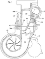
- Fig. 2
- in einer raumbildlichen, teils aufgebrochenen Darstellung die Abgasturbine des Abgasturboladers mit im Anschlussbereich am Abgaskrümmer positionierter Bremsklappe;
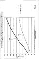
- Fig. 3
- eine Grafik zur mit der Motorbremsvorrichtung nach den
Fig. 1 und2 erzielbaren Motorbremsleistung in Prozent, aufgetragen über der Drehzahl der Brennkraftmaschine; - Fig. 4
- eine weitere Grafik mit Darstellung des über einen Sensor erfassten, mittleren relativen Abgasgegendrucks in bar;
- Fig. 5
- eine Grafik über den relativen Ladedruckverlauf (in bar) über die Drehzahl der Brennkraftmaschine;
- Fig. 6
- eine Schnittdarstellung durch die Abgasturbine und den Abgaskrümmer mit der Bremsklappe in einer Offenstellung; und
- Fig. 7
- eine Darstellung gemäß
Fig. 6 mit der Bremsklappe in einer Zwischenstellung.
- Fig. 1
- merely sketched an internal combustion engine for a commercial vehicle with an intake system, an exhaust system, an exhaust gas turbocharger and an engine braking device with a brake flap upstream of the exhaust gas turbine, which is controlled by an electronic engine control unit;
- Fig. 2
- in a three-dimensional, partially broken representation of the exhaust gas turbine of the exhaust gas turbocharger with positioned in the connection area at the exhaust manifold brake flap;
- Fig. 3
- a graph for with the engine braking device after the
Fig. 1 and2 achievable engine braking power in percent, plotted against the speed of the internal combustion engine; - Fig. 4
- a further graph showing the detected by a sensor, the average relative exhaust gas back pressure in bar;
- Fig. 5
- a graph on the relative boost pressure curve (in bar) over the speed of the internal combustion engine;
- Fig. 6
- a sectional view through the exhaust gas turbine and the exhaust manifold with the brake flap in an open position; and
- Fig. 7
- a representation according to
Fig. 6 with the brake flap in an intermediate position.
In der
Das Abgassystem 3 weist einen an die Brennräume der Brennkraftmaschine 1 angeschlossenen Abgaskrümmer 6 auf, der in noch zu beschreibender Weise an die Abgasturbine 8 eines Abgasturboladers 7 angeschlossen ist. Die Abgasturbine 8 treibt in bekannter Weise einen Verdichter 9 an, der über eine Leitung 10 mit dem Ansaugkrümmer 4 verbunden ist und der Verbrennungsluft unter einem definierten Ladedruck PL zu den Brennräumen der Brennkraftmaschine 1 fördert. Das über den Abgaskrümmer 3 und die Abgasturbine 8 abströmende Abgas wird über eine Abgasleitung 11 weiter abgeführt. Die weiteren Leitungen des Ansaugsystems 2 und des Abgassystems 3 der Brennkraftmaschine 1 im Kraftfahrzeug sind nicht dargestellt.The
Als Motorbremsvorrichtung weist die Brennkraftmaschine 1 eine Dekompressionsbremse (nicht dargestellt) auf, die auf die Gaswechselventile bzw. die Auslassventile der Brennkraftmaschine 1 wirkt. Ferner ist eine Bremsklappe 12 stromauf der Abgasturbine 8 vorgesehen, mittels der ein definierter Abgasgegendruck PA erzeugt werden kann.As an engine braking device, the internal combustion engine 1 a decompression brake (not shown), which acts on the gas exchange valves and the exhaust valves of the
Die Dekompressionsbremse kann in bekannter Weise gasgesteuert über den erhöhten Abgasgegendruck PA bei zumindest teilweise geschlossener Bremsklappe 12 initiiert werden, bei dem gezielt ein "Flattern" oder "Ventilspringen" der Auslassventile ausgelöst wird (zum Beispiel
Hinsichtlich der detaillierten Ausführung der Dekompressionsbremsen wird hilfsweise auf die genannten Veröffentlichungen verwiesen.With regard to the detailed execution of the decompression brakes refer to the publications mentioned in the alternative.
Die
Die hier beispielhaft einflügelig, das heißt maximal exzentrisch ausgeführte und auf der drehbar gelagerten Welle 13 befestigte Bremsklappe 12 ist zugleich als Strömungsleitelement ausgebildet, indem sie in der Offenstellung den vollen Querschnitt der Ausströmöffnung zur Abgasturbine 8 freigibt und in Zwischenstellungen bis hin zur vollen Schließung den Abgasstrom zum Turbinenrad (nicht ersichtlich) der Abgasturbine 8 derart ablenkt, dass der durch die Querschnittsverengung beschleunigte Abgasstrom das Turbinenrad ähnlich der Funktion einer variablen Turbinengeometrie bzw. gegebenenfalls in Stoßaufladung verstärkt antreibt.The example here single-wing, that is maximum eccentric running and mounted on the rotatably mounted
Die Bremsklappe 12 ragt dabei, wie aus der den geöffneten Zustand zeigenden
Alternativ zur eben beschriebenen Integration in den Abgaskrümmer 6 kann die Bremsklappe 12 aber auch, wie dies in der
Am Abgaskrümmer 6 ist ferner eine Halterung 14 befestigt, die ein zum Beispiel pneumatisches Stellglied 15 (zum Beispiel eine Kolben-Zylinder-Einheit) als Steller trägt, mittels dem über eine Kolbenstange 16 und einen Hebel 17 die Bremsklappe 12 betätigbar ist. Das Stellglied 15 kann mittels eines an eine Druckmittelquelle angeschlossenen Ventils (nicht dargestellt), zum Beispiel mittels eines Proportionalventils oder eines Taktventils, präzise in Stellungen zwischen offen und voll geschlossen beaufschlagt werden. Auch der Einsatz eines elektrischen Aktors wäre grundsätzlich ebenso möglich.At the
Zur vorteilhaften Verstellung bzw. Regelung der Bremsklappe 12 im Motorbremsbetrieb (vgl. auch
Des Weiteren werden über vorzugsweise als Drucksensoren ausgebildete Sensoren 19, 20 der Wert des Ladedrucks PL im Ansaugkrümmer 4 sowie der Wert des Abgasgegendrucks PA im Abgaskrümmer 6 erfasst und über entsprechende Signalleitungen (ohne Bezugszeichen) zum Steuergerät 18 geführt.Furthermore, the value of the boost pressure PL in the
Der Sensor 20, vorzugsweise ein Drucksensor, im Abgaskrümmer 6 ist funktionell stromauf der Abgasturbine 8 angeordnet. Dies zeigt die
Der Abgasturbolader 7 kann optional ein Bypassventil 22 aufweisen, mit dem zur Vermeidung eines zu hohen Ladedrucks PL Abgas an dem Turbinenrad der Abgasturbine 8 vorbeiführbar ist. Das Bypassventil 22 kann in die Abgasturbine 8 direkt integriert sein und ist deshalb in der Darstellung gemäß
Ferner kann die Brennkraftmaschine 1 ebenfalls rein optional eine Abgasrückführleitung 23 zwischen dem Ansaugsystem 4 und dem Abgassystem 3 aufweisen, in der ein über das Motorsteuergerät 18 steuerbares Abgasrückführventil 24 vorgesehen ist. Die Mündung der Abgasrückführleitung 23 in den Abgaskrümmer 6 liegt wie aus
Eine Motorbremsung im Schubbetrieb des Kraftfahrzeugs wird insbesondere durch das Signal B initiiert und bewirkt ein definiertes Schließen der Bremsklappe 12, abhängig unter anderem von der Drehzahl der Brennkraftmaschine und gegebenenfalls von der Anforderung der gewünschten Bremsleistung. Ferner kann temperaturabhängig gegebenenfalls ein Schließen des Abgasrückführventils 24 gesteuert sein.An engine braking in overrun mode of the motor vehicle is in particular initiated by the signal B and causes a defined closing of the
Die Schließstellung der Bremsklappe 12 definiert sich weiterhin aus dem Ladedruck PL im Ansaugkrümmer 4 und dem Abgasgegendruck PA im Abgaskrümmer 6 der Brennkraftmaschine.The closed position of the
Die
Wie den Grafiken ohne weiteres entnehmbar ist, ist die Motorbremsleistung bei einer erfindungsgemäßen Brennkraftmaschine 1 mit Abgasturboaufladung 7 signifikant erhöht (Kurve 25a). Gleiches gilt für den vorherrschenden Abgasgegendruck (Kurve 26a).As the graphics are readily apparent, the engine braking performance is significantly increased in an
Zudem weisen beide auf der erfindungsgemäßen Lösung basierenden Kurven 25a, 26a jeweils einen stark ansteigenden Gradienten auf.In addition, both
Insbesondere aber beachtlich und für die wesentliche Steigerung der spezifischen Motorbremsleistung (Kurve 25a) maßgeblich ist der schon bei niedrigen Drehzahlen n der Brennkraftmaschine 1 steil ansteigende Ladedruck PL (Kurve 27a), der sich durch die erfindungsgemäße Bremsklappe 12 mit entsprechender Strömungsleitfunktion einstellt.In particular, but considerable and significant for the significant increase of the specific engine braking performance (
Wie die Diagramme deutlich zeigen, wird mit der erfindungsgemäßen Bremsklappenanordnung stromauf der Abgasturbine, im Vergleich zu einer stromab der Abgasturbine angeordneten Bremsklappe, bedingt durch den deutlich gesteigerten Abgasgegendruck eine wesentlich höhere Motorbremsleistung erzielt, wobei es trotz der deutlich gestiegenen Motorbremsleistung zu keiner höheren thermischen Belastung der Brennkraftmaschine kommt.As the diagrams clearly show, with the inventive brake flap arrangement upstream of the exhaust gas turbine, compared to a downstream of the exhaust gas turbine arranged brake flap, due to the significantly increased exhaust back pressure achieved a much higher engine braking performance, despite the significantly increased engine braking power to no higher thermal load of Internal combustion engine comes.
Obwohl die gemessenen Werte an einer Brennkraftmaschine 1 mit einer gasdruckgesteuerten Dekompressionsbremse festgestellt wurden, sind sie auch für Brennkraftmaschinen 1 mit Abgasturboaufladung und Verwendung einer zwangsgesteuerten Dekompressionsbremse gleichermaßen relevant bzw. gültig.Although the measured values have been determined on an
In
Dabei liegt die Bremsklappe 12 hier beispielhaft derart in einer Vertiefung 31 einer Kanalwand 32 des Abgas-Strömungskanals 30 ein, dass diese im Wesentlichen oberflächenbündig an die unmittelbar an die Vertiefung 31 angrenzenden Wandbereiche 33 der Kanalwand 32 anschließt. Auf diese Weise wird mittels der Bremsklappe 12 ein kontinuierlicher Übergang zwischen den Wandbereichen 33 der Kanalwand 32 realisiert, mit dem ein besonders geringer Strömungswiderstand sichergestellt wird. Die Vertiefung 31 weist hier beispielhaft einen abgaskrümmerseitigen Bereich 34 und einen abgasturbinenseitigen Bereich 35 auf.Here, the
Des Weiteren ist in
Weiter ist die Vertiefung 38 hier derart konturangepasst zu dem Endbereich 37 der Bremsklappe 12 ausgebildet, dass die Bremsklappe 12 in der Schließstellung 36 mit ihrem Endbereich 37 in einer flächigen Anlage mit einem die Vertiefung 38 bildenden Vertiefungs-Wandbereich 40 ist. Dadurch wird das Abgas in der Schließstellung 36 der Bremsklappe 12 besonders effektiv rückgestaut. Zudem ist die Vertiefung 38 hier, in Abgas-Strömungsrichtung gesehen, stromab einer Messstelle 41 des Drucksensors 20 angeordnet.Further, the
In
Bevorzugt gibt die in der Zwischenstellung 42 angeordnete Bremsklappe 12 dabei 0,1% bis 20%, besonders bevorzugt 1,3% bis 11,1%, des maximalen Strömungsquerschnitts Qmax frei, um im Motorbremsbetrieb einen effektiven Antrieb des Turbinenrads 43 und gleichzeitig auch einen hohen Abgasdruckgegendruck sicherzustellen.Preferably, the
- 11
- BrennkraftmaschineInternal combustion engine
- 22
- Ansaugsystemintake system
- 33
- Abgassystemexhaust system
- 44
- Ansaugkrümmerintake manifold
- 55
- Drosselklappethrottle
- 66
- Abgaskrümmerexhaust manifold
- 6a6a
- Anschlussflanschflange
- 77
- Abgasturboladerturbocharger
- 88th
- Abgasturbineexhaust turbine
- 8a8a
- Anschlussflanschflange
- 8b8b
- Einströmkanalinflow
- 8c8c
- Anformungconformation
- 99
- Verdichtercompressor
- 1010
- Ansaugleitungsuction
- 1111
- Abgasleitungexhaust pipe
- 1212
- Bremsklappeairbrake
- 1313
- Wellewave
- 1414
- Halterholder
- 1515
- Stellgliedactuator
- 1616
- Stellkolbenactuating piston
- 1717
- Hebellever
- 1818
- MotorsteuergerätEngine control unit
- 1919
- Drucksensorpressure sensor
- 2020
- Drucksensorpressure sensor
- 2121
- Leitungmanagement
- 2222
- Bypassventilbypass valve
- 2323
- AbgasrückführleitungExhaust gas recirculation line
- 2424
- AbgasrückführventilExhaust gas recirculation valve
- 2525
- Kurve BremsleistungCurve braking power
- 2626
- Kurve Abgasgegendruck PACurve exhaust back pressure PA
- 2727
- Kurve Ladedruck PLCurve boost pressure PL
- 2828
- separate Baueinheitseparate assembly
- 2929
- Offenstellungopen position
- 3030
- Abgas-StrömungskanalExhaust gas flow channel
- 3131
- Vertiefungdeepening
- 3232
- Kanalwandchannel wall
- 3333
- Wandbereichwall area
- 3434
- abgaskrümmerseitiger BereichExhaust manifold side area
- 3535
- abgasturbinenseitiger BereichExhaust gas side area
- 3636
- Schließstellungclosed position
- 3737
- Endbereichend
- 3838
- Vertiefungdeepening
- 3939
- Fixierbereichfusing
- 39a39a
- Wandbereichwall area
- 4040
- Vertiefungs-WandbereichPit wall area
- 4141
- Messstellemeasuring point
- 4242
- Zwischenstellungintermediate position
- 4343
- Turbinenradturbine
- Qmax Q max
- maximaler Strömungsquerschnittmaximum flow cross section
- QzQz
- Strömungsquerschnitt ZwischenstellungFlow cross section intermediate position
Claims (19)
- Engine braking device for a combustion engine (1) in motor vehicles, which has an intake system (2), an exhaust system (3), gas exchange valves associated with the combustion engine, exhaust turbocharging by means of at least one exhaust turbocharger (7) integrated into the exhaust system (3) and the intake system (2) and of single-flow or multi-flow design, and an engine braking unit, wherein the engine braking unit has a decompression brake, which influences at least one outlet valve of the gas exchange valves, and each flow has a brake flap (12), which is arranged in the exhaust system and causes the exhaust gas to build up, and wherein the brake flap (12) is arranged directly upstream of and outside a turbine housing of an exhaust turbine (8) of the exhaust turbocharger (7), characterized in that the brake flap (12) is designed as a flow guiding flap which influences the admission of a gas flow to the exhaust turbine (8) and which, in the engine braking mode, is arranged in an intermediate position (42) between an open position (29) and a closed position (36), in which intermediate position the brake flap (12) opens up a flow cross section (QZ) smaller than the maximum flow cross section (Qmax) and is arranged such that the flow cross section of the exhaust flow duct (30) narrows in the manner of a nozzle in the exhaust flow direction by means of the brake flap (12) and the exhaust flow flowing past the brake flap (12) is accelerated, wherein the brake flap (12) arranged in the intermediate position (42) opens up a flow cross section which lies in a range from 0.1% to 20% of the maximum flow cross section, and wherein the exhaust flow flowing past the brake flap (12) forms the only exhaust flow flowing to the turbine wheel (43).
- Engine braking device according to Claim 1, characterized in that the exhaust turbine (8), in particular a turbine housing of the exhaust turbine (8), is coupled fluidically to an exhaust manifold (6'), to which the exhaust gas is admitted via at least one, preferably a plurality of, cylinders of the combustion engine (1), wherein a separate module (28) having the brake flap (12) is installed between the exhaust turbine (8) and the exhaust manifold (6'), in particular between a turbine housing of the exhaust turbine (8) and the exhaust manifold (6'), and hence directly upstream of and outside a turbine housing of the exhaust turbine (8).
- Engine braking device according to Claim 1, characterized in that the exhaust turbine (8), in particular a turbine housing of the exhaust turbine (8), is mounted directly on an exhaust manifold (6), to which the exhaust gas is admitted via at least one, preferably a plurality of, cylinders of the combustion engine (1), and in that the brake flap (12) is arranged in the region of the exhaust manifold (6) and hence directly upstream of and outside a turbine housing of the exhaust turbine (8).
- Engine braking device according to Claim 2 or 3, characterized in that the brake flap (12) is arranged in the region of a connecting flange (6a) of a housing of the separate module (28) or in the region of a connecting flange (6a) of the exhaust manifold (6), in particular on a wall region of the housing of the separate module (28) or of the exhaust manifold (6) which is adjacent to the connecting flange, the brake flap being, in particular, arranged pivotably in such a way, in the region of or on a connecting flange (6a) of the housing of the separate module (28) or of the exhaust manifold (6) leading to the exhaust turbine (8), that it exposes the exhaust gas cross section in the open state and reduces the exhaust gas cross section in the closed state.
- Engine braking device according to one of the preceding claims, characterized in that the brake flap (12) projects beyond the connecting flange (6a) into the inflow duct (8b) of the exhaust turbine (8), at least by means of a free end region, in an open position, in particular in the completely open state.
- Engine braking device according to one of the preceding claims, characterized in that, in the case of multi-stage, in particular two-stage charging, the brake flap (12) is arranged upstream of a first exhaust turbine of a first exhaust turbocharger, as seen in the direction of flow, and/or in that each flow of the exhaust turbine (8) is assigned a brake flap (12).
- Engine braking device according to one of the preceding claims, characterized in that, in the engine braking mode (B), the brake flap (12) is controlled by means of a closed-loop and/or open-loop control device (18) in a manner dependent on the exhaust gas backpressure (PA) upstream of the brake flap (12) and/or in a manner dependent on the boost pressure (PL) in the intake system (2) of the combustion engine (1).
- Engine braking device according to Claim 7, characterized in that a sensor (20), in particular a pressure sensor, is arranged in the exhaust system (3) upstream of the brake flap (12) in order to detect the exhaust gas backpressure (PA) and/or in that a sensor (19), in particular a pressure sensor, is arranged downstream of a compressor (9), in the region of the intake manifold (19), in order to detect the boost pressure (PL).
- Engine braking device according to Claim 8, characterized in that the sensor (20) for detecting the exhaust gas backpressure (PA) is arranged functionally upstream of the brake flap (12), such that the sensor (20) is arranged remote from and spaced apart from this upstream region and is connected to the region situated upstream of the brake flap (12) by a line (21) which opens into the exhaust system (3) upstream of the brake flap (12), wherein provision is preferably made for said line (21) to be designed as a line (21) which falls towards the sensor, relative to the direction of a vertical axis.
- Engine braking device according to one of the preceding claims, characterized in that, to actuate the brake flap (12), an electric actuator controlled by an open-loop and/or closed-loop control device, in particular by an electronic engine control unit (18), is provided or, alternatively, a positioner (15), preferably a pneumatically actuated positioner, and a valve connected thereto are provided.
- Engine braking device according to Claim 10, characterized in that at least one brake signal (B), which initiates the engine braking, and/or a load signal (α) and/or an exhaust gas backpressure (PA) and/or a boost pressure (PL) in the intake system (4) can be fed to the open-loop and/or closed-loop control device, in particular to the electronic engine control unit (18), and at least the position of the brake flap (12) can be controlled thereby in accordance with a demanded engine braking power.
- Engine braking device according to one of the preceding claims, characterized in that exhaust gas recirculation from the exhaust system (3) to the intake system (4) with an exhaust gas recirculation valve (24), preferably controlled electrically or pneumatically, in an exhaust gas recirculation line (23) is provided.
- Engine braking device according to one of the preceding claims, characterized in that a decompression braking effect is controlled by the exhaust gas backpressure (PA) or in that a decompression braking effect is brought about by a device which is superimposed on the valve control and which is preferably electrically or pneumatically or hydraulically controlled.
- Engine braking device according to one of the preceding claims, characterized in that the brake flap (12), in its open position in which it opens up the full cross section of the outflow opening, is at least regionally arranged superficially flush with a duct wall (32) of an exhaust flow duct (30) which forms the outflow opening, preferably, the brake flap (12) is received and/or lies in a depression (31) in the wall and, in a substantially superficially flush manner, adjoins those wall regions (33) of the duct wall (32) of an exhaust flow duct (30) which forms the outflow opening which directly adjoin the depression (31).
- Engine braking device according to one of the preceding claims, characterized in that the brake flap (12) arranged in the intermediate position opens up a flow cross section which lies in a range from 1% to 12%, preferably from 1.3% to 11.1%, of the maximum flow cross section.
- Method for operating an engine braking device for a combustion engine (1) in motor vehicles, wherein the engine braking device has an intake system (2), an exhaust system (3), gas exchange valves associated with the combustion engine, exhaust turbocharging by means of at least one exhaust turbocharger (7) integrated into the exhaust system (3) and the intake system (2) and of single-flow or multi-flow design, and an engine braking unit, wherein the engine braking unit has a decompression brake, which influences at least one outlet valve of the gas exchange valves, and each flow has a brake flap (12), which is arranged in the exhaust system and causes the exhaust gas to build up, and wherein the brake flap (12) is arranged directly upstream of and outside a turbine housing of an exhaust turbine (8) of the exhaust turbocharger (7), characterized in that the brake flap (12) forms a flow guiding flap, by means of which a defined gas flow is admitted to the exhaust turbine (8) in accordance with the position of the brake flap (12) wherein the brake flap (12), in the engine braking mode, is arranged in an intermediate position (42) between an open position (29) and a closed position (36), in which intermediate position the brake flap (12) opens up a flow cross section (QZ) smaller than the maximum flow cross section (Qmax) and is arranged such that the flow cross section of the exhaust flow duct (30) narrows in the manner of a nozzle in the exhaust flow direction by means of the brake flap (12) and the exhaust flow flowing past the brake flap (12) is accelerated, wherein the brake flap (12) arranged in the intermediate position (42) opens up a flow cross section which lies in a range from 0.1% to 20% of the maximum flow cross section, and wherein the exhaust flow flowing past the brake flap (12) forms the only exhaust flow flowing to the turbine wheel (43).
- Method according to Claim 16, characterized in that the brake flap (12) arranged in the intermediate position opens up a flow cross section which lies in a range from 1% to 12%, preferably from 1.3% to 11.1%, of the maximum flow cross section.
- Method according to Claim 16 or 17, characterized in that the brake flap (12), in the non-engine braking mode, opens up a first flow cross section, preferably the maximum flow cross section, and in that the brake flap (12), in the engine braking mode, opens up a second flow cross section smaller than the first flow cross section.
- Vehicle having an engine braking device according to one of Claims 1 to 15.
Applications Claiming Priority (1)
| Application Number | Priority Date | Filing Date | Title |
|---|---|---|---|
| ATA908/2014A AT516513B1 (en) | 2014-12-15 | 2014-12-15 | An engine braking device for an internal combustion engine and method for operating an engine braking device |
Publications (2)
| Publication Number | Publication Date |
|---|---|
| EP3034844A1 EP3034844A1 (en) | 2016-06-22 |
| EP3034844B1 true EP3034844B1 (en) | 2019-05-15 |
Family
ID=54849744
Family Applications (1)
| Application Number | Title | Priority Date | Filing Date |
|---|---|---|---|
| EP15003532.7A Revoked EP3034844B1 (en) | 2014-12-15 | 2015-12-11 | Engine braking device for a combustion engine and method for operating an engine braking device |
Country Status (6)
| Country | Link |
|---|---|
| US (1) | US10267238B2 (en) |
| EP (1) | EP3034844B1 (en) |
| CN (1) | CN105822379B (en) |
| AT (1) | AT516513B1 (en) |
| BR (1) | BR102015031170B1 (en) |
| RU (1) | RU2709893C2 (en) |
Families Citing this family (9)
| Publication number | Priority date | Publication date | Assignee | Title |
|---|---|---|---|---|
| RU2706246C2 (en) * | 2016-11-18 | 2019-11-15 | Федеральное Государственное Казенное Военное Образовательное Учреждение Высшего Образования Военный Учебно-Научный Центр Сухопутных Войск "Общевойсковая Академия Вооруженных Сил Российской Федерации" | Start-up device of gasoline internal combustion engine of automobile |
| CN106438058A (en) * | 2016-12-07 | 2017-02-22 | 东风商用车有限公司 | Engine exhaust pipe with exhaust braking butterfly valve |
| DE102017115599A1 (en) | 2017-07-12 | 2019-01-17 | Man Truck & Bus Ag | Internal combustion engine, in particular as a drive motor for a vehicle |
| CN108150315B (en) * | 2017-12-29 | 2021-05-18 | 潍柴动力股份有限公司 | EGR exhaust treatment device and automobile |
| AT521954B1 (en) * | 2019-01-31 | 2020-07-15 | MAN TRUCK & BUS OESTERREICH GesmbH | Exhaust gas routing device for an internal combustion engine |
| CN109882298B (en) * | 2019-03-19 | 2021-08-20 | 潍柴动力股份有限公司 | Adjusting device and engine |
| CN113047966B (en) * | 2021-03-04 | 2022-07-12 | 广西玉柴机器股份有限公司 | Method and system for adjusting braking power in engine cylinder and related device |
| US11608775B1 (en) | 2022-07-26 | 2023-03-21 | Garrett Transportation I Inc. | Control method for variable turbine nozzle of turbocharger during engine braking |
| CN115355071B (en) * | 2022-10-24 | 2023-02-10 | 龙口中宇热管理系统科技有限公司 | In-cylinder brake mechanism and method for engine |
Citations (10)
| Publication number | Priority date | Publication date | Assignee | Title |
|---|---|---|---|---|
| DE2648676A1 (en) | 1976-03-11 | 1977-09-22 | Josef V Illichmann | Engine brake using exhaust gas back pressure - has servo actuated flap which pivots into recess out of gas flow |
| US6155049A (en) | 1998-03-03 | 2000-12-05 | Daimlerchrysler Ag | Method of controlling the charge air mass flow of a supercharged internal combustion engine |
| US20030178002A1 (en) | 2003-02-27 | 2003-09-25 | Israel Mark A. | Apparatus and method to operate an engine exhaust brake together with an exhaust gas recirculation system |
| US20060230759A1 (en) | 2005-04-13 | 2006-10-19 | Semrau H A | Variable geometry turbocharger |
| US20070137200A1 (en) | 2005-12-20 | 2007-06-21 | Franz Rammer | Device for increasing the braking power of a multi-cylinder internal combustion engine of a vehicle during an engine braking operation |
| WO2010151391A1 (en) | 2009-06-25 | 2010-12-29 | International Engine Intellectual Property Company, Llc | Brake valve for engine braking |
| US20120017868A1 (en) | 2010-07-26 | 2012-01-26 | Man Nutzfahrzeuge Oesterreich Ag | Method and device for engine braking |
| US20120017869A1 (en) | 2010-07-26 | 2012-01-26 | Man Nutzfahrzeuge Osterreich Ag | Method and device for engine braking |
| EP2607650A2 (en) | 2011-12-23 | 2013-06-26 | MAN Truck & Bus Österreich AG | Throttling assembly of a turbocharger |
| EP2679787A1 (en) | 2012-06-28 | 2014-01-01 | MAN Truck & Bus AG | Method and device for controlling a brake valve |
Family Cites Families (24)
| Publication number | Priority date | Publication date | Assignee | Title |
|---|---|---|---|---|
| US3423926A (en) * | 1966-08-31 | 1969-01-28 | Garrett Corp | Turbocharger control arrangement |
| AT279275B (en) * | 1968-08-07 | 1970-02-25 | Maschf Augsburg Nuernberg Ag | Exhaust throttle for exhaust brakes on supercharged combustion engines |
| DE3922884A1 (en) | 1989-07-12 | 1991-01-24 | Man Nutzfahrzeuge Ag | ENGINE BRAKE FOR AIR COMPRESSING ENGINES |
| DE19540060A1 (en) * | 1995-10-27 | 1997-04-30 | Daimler Benz Ag | Engine brake device |
| AT411545B (en) * | 2001-05-14 | 2004-02-25 | Man Steyr Ag | INTERNAL COMBUSTION ENGINE IN A VEHICLE WITH AN ENGINE BRAKING DEVICE AND AN EXHAUST GAS RECIRCULATOR |
| ITTO20010615A1 (en) * | 2001-06-26 | 2002-12-26 | Iveco Motorenforschung Ag | ENDOTHERMAL-TURBOCHARGER ENGINE UNIT FOR A VEHICLE, IN PARTICULAR FOR AN INDUSTRIAL VEHICLE, WITH CONTROL OF THE POWER OF THE |
| DE10239110B4 (en) * | 2002-08-27 | 2004-08-19 | Caterpillar Motoren Gmbh & Co. Kg | Charging system for an internal combustion engine |
| EP1710415A1 (en) * | 2005-04-04 | 2006-10-11 | ABB Turbo Systems AG | Multiple step turbocharging |
| CN101268267B (en) * | 2005-09-15 | 2010-05-26 | 沃尔沃拉斯特瓦格纳公司 | Method for internal combustion engine with exhaust recirculation |
| DE102006058102B4 (en) * | 2006-12-09 | 2020-08-06 | Daimler Ag | Internal combustion engine with exhaust gas turbocharger |
| GB0717212D0 (en) * | 2007-09-05 | 2007-10-17 | Cummins Turbo Tech Ltd | Multi-stage turbocharger system |
| DE102008008721A1 (en) * | 2008-02-12 | 2009-08-20 | Knorr-Bremse Systeme für Nutzfahrzeuge GmbH | Method and device for supplying a compressor with compressed air in an internal combustion engine |
| DE102008008723B4 (en) * | 2008-02-12 | 2013-07-11 | Knorr-Bremse Systeme für Nutzfahrzeuge GmbH | Method and device for generating compressed air and for blowing the same in an internal combustion engine |
| DE102008061412A1 (en) | 2008-07-11 | 2010-01-14 | Man Nutzfahrzeuge Ag | Hydraulic valve and EVB clearance compensation |
| DE102009019437A1 (en) * | 2009-04-29 | 2010-11-04 | Man Nutzfahrzeuge Ag | Device for increasing the braking power of a multi-cylinder internal combustion engine of a vehicle during engine braking operation |
| WO2011002565A1 (en) * | 2009-06-29 | 2011-01-06 | International Engine Intellectual Property Company, Llc | Engine brake using brake valve and partial admission flow turbine turbocharger |
| JP2012097604A (en) * | 2010-10-29 | 2012-05-24 | Isuzu Motors Ltd | Method and device for controlling exhaust brake of internal combustion engine |
| DE102011115296A1 (en) * | 2011-09-29 | 2013-04-04 | Mtu Friedrichshafen Gmbh | Two-stage charging device |
| AT512567B1 (en) * | 2012-03-01 | 2014-03-15 | Man Truck & Bus Oesterreich Ag | Function module with an exhaust gas turbocharger and an exhaust manifold |
| AT512910B1 (en) * | 2012-04-02 | 2013-12-15 | Man Truck & Bus Oesterreich Ag | Method and device for controlling engine braking operation on internal combustion engines |
| EP2672091B1 (en) * | 2012-06-07 | 2015-02-25 | Daf Trucks N.V. | Controlling a compression release brake |
| US20140214308A1 (en) * | 2013-01-29 | 2014-07-31 | Cummins Ip, Inc. | Apparatus, system and method for increasing braking power |
| DE102013011587A1 (en) * | 2013-07-10 | 2015-01-15 | Daimler Ag | Internal combustion engine for a motor vehicle and method for operating such an internal combustion engine |
| US10570834B2 (en) * | 2016-10-27 | 2020-02-25 | Cummins Inc. | Supercharging for improved engine braking and transient performance |
-
2014
- 2014-12-15 AT ATA908/2014A patent/AT516513B1/en active
-
2015
- 2015-12-11 RU RU2015153191A patent/RU2709893C2/en active
- 2015-12-11 US US14/966,553 patent/US10267238B2/en active Active
- 2015-12-11 CN CN201511036258.8A patent/CN105822379B/en active Active
- 2015-12-11 EP EP15003532.7A patent/EP3034844B1/en not_active Revoked
- 2015-12-11 BR BR102015031170-2A patent/BR102015031170B1/en active IP Right Grant
Patent Citations (10)
| Publication number | Priority date | Publication date | Assignee | Title |
|---|---|---|---|---|
| DE2648676A1 (en) | 1976-03-11 | 1977-09-22 | Josef V Illichmann | Engine brake using exhaust gas back pressure - has servo actuated flap which pivots into recess out of gas flow |
| US6155049A (en) | 1998-03-03 | 2000-12-05 | Daimlerchrysler Ag | Method of controlling the charge air mass flow of a supercharged internal combustion engine |
| US20030178002A1 (en) | 2003-02-27 | 2003-09-25 | Israel Mark A. | Apparatus and method to operate an engine exhaust brake together with an exhaust gas recirculation system |
| US20060230759A1 (en) | 2005-04-13 | 2006-10-19 | Semrau H A | Variable geometry turbocharger |
| US20070137200A1 (en) | 2005-12-20 | 2007-06-21 | Franz Rammer | Device for increasing the braking power of a multi-cylinder internal combustion engine of a vehicle during an engine braking operation |
| WO2010151391A1 (en) | 2009-06-25 | 2010-12-29 | International Engine Intellectual Property Company, Llc | Brake valve for engine braking |
| US20120017868A1 (en) | 2010-07-26 | 2012-01-26 | Man Nutzfahrzeuge Oesterreich Ag | Method and device for engine braking |
| US20120017869A1 (en) | 2010-07-26 | 2012-01-26 | Man Nutzfahrzeuge Osterreich Ag | Method and device for engine braking |
| EP2607650A2 (en) | 2011-12-23 | 2013-06-26 | MAN Truck & Bus Österreich AG | Throttling assembly of a turbocharger |
| EP2679787A1 (en) | 2012-06-28 | 2014-01-01 | MAN Truck & Bus AG | Method and device for controlling a brake valve |
Non-Patent Citations (2)
| Title |
|---|
| "New Holset Turbochargers for Small Diesel", THE LATEST TURBOCHARGER NEWS HTI, 2011, pages 1 - 10, XP055688650 |
| "Smart thinking behind latest Holset VGTTM actuators", THE LATEST TURBOCHARGER NEWS, 2008, pages 1 - 14, XP055688658 |
Also Published As
| Publication number | Publication date |
|---|---|
| BR102015031170B1 (en) | 2022-09-13 |
| RU2015153191A (en) | 2017-06-20 |
| RU2709893C2 (en) | 2019-12-23 |
| BR102015031170A2 (en) | 2016-09-06 |
| US10267238B2 (en) | 2019-04-23 |
| EP3034844A1 (en) | 2016-06-22 |
| AT516513A4 (en) | 2016-06-15 |
| RU2015153191A3 (en) | 2019-06-20 |
| CN105822379B (en) | 2019-12-17 |
| CN105822379A (en) | 2016-08-03 |
| AT516513B1 (en) | 2016-06-15 |
| US20160169128A1 (en) | 2016-06-16 |
Similar Documents
| Publication | Publication Date | Title |
|---|---|---|
| EP3034844B1 (en) | Engine braking device for a combustion engine and method for operating an engine braking device | |
| EP3034843B1 (en) | Method for controlling an engine braking device and engine braking device | |
| EP2412954B1 (en) | Method for braking a motor | |
| EP2412955B1 (en) | Method for braking a motor | |
| EP1809876B1 (en) | Method and device for controlling or regulating the boost pressure of an internal combustion engine comprising a compressor | |
| DE102008048681B4 (en) | Internal combustion engine with two loaders and method for operating the same | |
| EP2679787B1 (en) | Method and device for controlling a brake valve | |
| DE102010004657B4 (en) | Fresh gas supply device for an internal combustion engine and method for operating such a fresh gas supply device | |
| DE102004056894A1 (en) | Method and device for controlling the boost pressure of an internal combustion engine | |
| DE112015001521T5 (en) | Method for controlling a turbocharged engine and control device of a turbocharged engine | |
| WO2006037564A1 (en) | Method and device for increasing the torque of a reciprocating piston internal combustion engine, especially a diesel engine | |
| AT502997A1 (en) | DEVICE FOR INCREASING THE BRAKING PERFORMANCE OF A MULTI-CYLINDER INTERNAL COMBUSTION ENGINE OF A VEHICLE DURING ENGINE BRAKE OPERATION | |
| DE19841330A1 (en) | Device to control IC engine which is charged with charger has an induction line leading to charger, second throttle organ connected to control unit, and transmitting signals | |
| EP2634393B1 (en) | Functional module with an exhaust gas turbocharger and an exhaust manifold | |
| EP2246543A1 (en) | Cylinder head with two exhaust manifolds and method to operate an internal combustion engine with such a cylinder head | |
| EP1762716B1 (en) | Exhaust brake with bypass channel | |
| DE4024572C2 (en) | Register charging for internal combustion engines in commercial vehicles | |
| WO2008017440A1 (en) | Internal combustion engine | |
| DE10133669A1 (en) | Exhaust gas turbocharger in an internal combustion engine | |
| DE102012200014A1 (en) | Multi-cylinder internal combustion engine and method for operating such a multi-cylinder internal combustion engine | |
| DE102010029109A1 (en) | Driving apparatus i.e. combustion engine, operating device for motor car, has waste gate valve comprising valve flap that releases bypass channel and closes inlet and exhaust passages of turbine simultaneously in respective position | |
| EP2602449B1 (en) | Combustion engine with exhaust gas turbocharger and exhaust gas cooler and method for controlling/regulating the working temperature of the exhaust gas turbocharger | |
| EP2405111A1 (en) | Combustion engine with a charging device for compressing an operating gas | |
| DE102015218335B4 (en) | Turbine for an exhaust gas turbocharger | |
| WO2005071243A1 (en) | Compressor mounted in the intake tract of an internal combustion engine |
Legal Events
| Date | Code | Title | Description |
|---|---|---|---|
| PUAI | Public reference made under article 153(3) epc to a published international application that has entered the european phase |
Free format text: ORIGINAL CODE: 0009012 |
|
| AK | Designated contracting states |
Kind code of ref document: A1 Designated state(s): AL AT BE BG CH CY CZ DE DK EE ES FI FR GB GR HR HU IE IS IT LI LT LU LV MC MK MT NL NO PL PT RO RS SE SI SK SM TR |
|
| AX | Request for extension of the european patent |
Extension state: BA ME |
|
| STAA | Information on the status of an ep patent application or granted ep patent |
Free format text: STATUS: REQUEST FOR EXAMINATION WAS MADE |
|
| 17P | Request for examination filed |
Effective date: 20161221 |
|
| RBV | Designated contracting states (corrected) |
Designated state(s): AL AT BE BG CH CY CZ DE DK EE ES FI FR GB GR HR HU IE IS IT LI LT LU LV MC MK MT NL NO PL PT RO RS SE SI SK SM TR |
|
| STAA | Information on the status of an ep patent application or granted ep patent |
Free format text: STATUS: EXAMINATION IS IN PROGRESS |
|
| 17Q | First examination report despatched |
Effective date: 20170517 |
|
| GRAP | Despatch of communication of intention to grant a patent |
Free format text: ORIGINAL CODE: EPIDOSNIGR1 |
|
| STAA | Information on the status of an ep patent application or granted ep patent |
Free format text: STATUS: GRANT OF PATENT IS INTENDED |
|
| INTG | Intention to grant announced |
Effective date: 20171215 |
|
| GRAJ | Information related to disapproval of communication of intention to grant by the applicant or resumption of examination proceedings by the epo deleted |
Free format text: ORIGINAL CODE: EPIDOSDIGR1 |
|
| STAA | Information on the status of an ep patent application or granted ep patent |
Free format text: STATUS: EXAMINATION IS IN PROGRESS |
|
| INTC | Intention to grant announced (deleted) | ||
| GRAP | Despatch of communication of intention to grant a patent |
Free format text: ORIGINAL CODE: EPIDOSNIGR1 |
|
| STAA | Information on the status of an ep patent application or granted ep patent |
Free format text: STATUS: GRANT OF PATENT IS INTENDED |
|
| INTG | Intention to grant announced |
Effective date: 20181204 |
|
| GRAS | Grant fee paid |
Free format text: ORIGINAL CODE: EPIDOSNIGR3 |
|
| GRAA | (expected) grant |
Free format text: ORIGINAL CODE: 0009210 |
|
| STAA | Information on the status of an ep patent application or granted ep patent |
Free format text: STATUS: THE PATENT HAS BEEN GRANTED |
|
| AK | Designated contracting states |
Kind code of ref document: B1 Designated state(s): AL AT BE BG CH CY CZ DE DK EE ES FI FR GB GR HR HU IE IS IT LI LT LU LV MC MK MT NL NO PL PT RO RS SE SI SK SM TR |
|
| REG | Reference to a national code |
Ref country code: CH Ref legal event code: EP |
|
| REG | Reference to a national code |
Ref country code: DE Ref legal event code: R096 Ref document number: 502015009036 Country of ref document: DE |
|
| REG | Reference to a national code |
Ref country code: IE Ref legal event code: FG4D Free format text: LANGUAGE OF EP DOCUMENT: GERMAN |
|
| REG | Reference to a national code |
Ref country code: NL Ref legal event code: FP |
|
| REG | Reference to a national code |
Ref country code: SE Ref legal event code: TRGR |
|
| REG | Reference to a national code |
Ref country code: LT Ref legal event code: MG4D |
|
| PG25 | Lapsed in a contracting state [announced via postgrant information from national office to epo] |
Ref country code: NO Free format text: LAPSE BECAUSE OF FAILURE TO SUBMIT A TRANSLATION OF THE DESCRIPTION OR TO PAY THE FEE WITHIN THE PRESCRIBED TIME-LIMIT Effective date: 20190815 Ref country code: HR Free format text: LAPSE BECAUSE OF FAILURE TO SUBMIT A TRANSLATION OF THE DESCRIPTION OR TO PAY THE FEE WITHIN THE PRESCRIBED TIME-LIMIT Effective date: 20190515 Ref country code: FI Free format text: LAPSE BECAUSE OF FAILURE TO SUBMIT A TRANSLATION OF THE DESCRIPTION OR TO PAY THE FEE WITHIN THE PRESCRIBED TIME-LIMIT Effective date: 20190515 Ref country code: AL Free format text: LAPSE BECAUSE OF FAILURE TO SUBMIT A TRANSLATION OF THE DESCRIPTION OR TO PAY THE FEE WITHIN THE PRESCRIBED TIME-LIMIT Effective date: 20190515 Ref country code: PT Free format text: LAPSE BECAUSE OF FAILURE TO SUBMIT A TRANSLATION OF THE DESCRIPTION OR TO PAY THE FEE WITHIN THE PRESCRIBED TIME-LIMIT Effective date: 20190915 Ref country code: LT Free format text: LAPSE BECAUSE OF FAILURE TO SUBMIT A TRANSLATION OF THE DESCRIPTION OR TO PAY THE FEE WITHIN THE PRESCRIBED TIME-LIMIT Effective date: 20190515 Ref country code: ES Free format text: LAPSE BECAUSE OF FAILURE TO SUBMIT A TRANSLATION OF THE DESCRIPTION OR TO PAY THE FEE WITHIN THE PRESCRIBED TIME-LIMIT Effective date: 20190515 |
|
| PG25 | Lapsed in a contracting state [announced via postgrant information from national office to epo] |
Ref country code: BG Free format text: LAPSE BECAUSE OF FAILURE TO SUBMIT A TRANSLATION OF THE DESCRIPTION OR TO PAY THE FEE WITHIN THE PRESCRIBED TIME-LIMIT Effective date: 20190815 Ref country code: RS Free format text: LAPSE BECAUSE OF FAILURE TO SUBMIT A TRANSLATION OF THE DESCRIPTION OR TO PAY THE FEE WITHIN THE PRESCRIBED TIME-LIMIT Effective date: 20190515 Ref country code: LV Free format text: LAPSE BECAUSE OF FAILURE TO SUBMIT A TRANSLATION OF THE DESCRIPTION OR TO PAY THE FEE WITHIN THE PRESCRIBED TIME-LIMIT Effective date: 20190515 Ref country code: GR Free format text: LAPSE BECAUSE OF FAILURE TO SUBMIT A TRANSLATION OF THE DESCRIPTION OR TO PAY THE FEE WITHIN THE PRESCRIBED TIME-LIMIT Effective date: 20190816 |
|
| PG25 | Lapsed in a contracting state [announced via postgrant information from national office to epo] |
Ref country code: SK Free format text: LAPSE BECAUSE OF FAILURE TO SUBMIT A TRANSLATION OF THE DESCRIPTION OR TO PAY THE FEE WITHIN THE PRESCRIBED TIME-LIMIT Effective date: 20190515 Ref country code: CZ Free format text: LAPSE BECAUSE OF FAILURE TO SUBMIT A TRANSLATION OF THE DESCRIPTION OR TO PAY THE FEE WITHIN THE PRESCRIBED TIME-LIMIT Effective date: 20190515 Ref country code: RO Free format text: LAPSE BECAUSE OF FAILURE TO SUBMIT A TRANSLATION OF THE DESCRIPTION OR TO PAY THE FEE WITHIN THE PRESCRIBED TIME-LIMIT Effective date: 20190515 Ref country code: DK Free format text: LAPSE BECAUSE OF FAILURE TO SUBMIT A TRANSLATION OF THE DESCRIPTION OR TO PAY THE FEE WITHIN THE PRESCRIBED TIME-LIMIT Effective date: 20190515 Ref country code: EE Free format text: LAPSE BECAUSE OF FAILURE TO SUBMIT A TRANSLATION OF THE DESCRIPTION OR TO PAY THE FEE WITHIN THE PRESCRIBED TIME-LIMIT Effective date: 20190515 |
|
| REG | Reference to a national code |
Ref country code: DE Ref legal event code: R026 Ref document number: 502015009036 Country of ref document: DE |
|
| PLBI | Opposition filed |
Free format text: ORIGINAL CODE: 0009260 |
|
| PLBI | Opposition filed |
Free format text: ORIGINAL CODE: 0009260 |
|
| PLAX | Notice of opposition and request to file observation + time limit sent |
Free format text: ORIGINAL CODE: EPIDOSNOBS2 |
|
| PG25 | Lapsed in a contracting state [announced via postgrant information from national office to epo] |
Ref country code: SM Free format text: LAPSE BECAUSE OF FAILURE TO SUBMIT A TRANSLATION OF THE DESCRIPTION OR TO PAY THE FEE WITHIN THE PRESCRIBED TIME-LIMIT Effective date: 20190515 |
|
| 26 | Opposition filed |
Opponent name: VOLVO TRUCK CORPORATION Effective date: 20200204 |
|
| 26 | Opposition filed |
Opponent name: DAF TRUCKS N.V. OPERATIONS Effective date: 20200214 |
|
| PG25 | Lapsed in a contracting state [announced via postgrant information from national office to epo] |
Ref country code: TR Free format text: LAPSE BECAUSE OF FAILURE TO SUBMIT A TRANSLATION OF THE DESCRIPTION OR TO PAY THE FEE WITHIN THE PRESCRIBED TIME-LIMIT Effective date: 20190515 |
|
| PG25 | Lapsed in a contracting state [announced via postgrant information from national office to epo] |
Ref country code: PL Free format text: LAPSE BECAUSE OF FAILURE TO SUBMIT A TRANSLATION OF THE DESCRIPTION OR TO PAY THE FEE WITHIN THE PRESCRIBED TIME-LIMIT Effective date: 20190515 |
|
| PG25 | Lapsed in a contracting state [announced via postgrant information from national office to epo] |
Ref country code: SI Free format text: LAPSE BECAUSE OF FAILURE TO SUBMIT A TRANSLATION OF THE DESCRIPTION OR TO PAY THE FEE WITHIN THE PRESCRIBED TIME-LIMIT Effective date: 20190515 |
|
| PLAF | Information modified related to communication of a notice of opposition and request to file observations + time limit |
Free format text: ORIGINAL CODE: EPIDOSCOBS2 |
|
| REG | Reference to a national code |
Ref country code: CH Ref legal event code: PL |
|
| REG | Reference to a national code |
Ref country code: BE Ref legal event code: MM Effective date: 20191231 |
|
| PG25 | Lapsed in a contracting state [announced via postgrant information from national office to epo] |
Ref country code: MC Free format text: LAPSE BECAUSE OF FAILURE TO SUBMIT A TRANSLATION OF THE DESCRIPTION OR TO PAY THE FEE WITHIN THE PRESCRIBED TIME-LIMIT Effective date: 20190515 |
|
| GBPC | Gb: european patent ceased through non-payment of renewal fee |
Effective date: 20191211 |
|
| PLBB | Reply of patent proprietor to notice(s) of opposition received |
Free format text: ORIGINAL CODE: EPIDOSNOBS3 |
|
| PG25 | Lapsed in a contracting state [announced via postgrant information from national office to epo] |
Ref country code: IE Free format text: LAPSE BECAUSE OF NON-PAYMENT OF DUE FEES Effective date: 20191211 Ref country code: GB Free format text: LAPSE BECAUSE OF NON-PAYMENT OF DUE FEES Effective date: 20191211 Ref country code: LU Free format text: LAPSE BECAUSE OF NON-PAYMENT OF DUE FEES Effective date: 20191211 |
|
| PG25 | Lapsed in a contracting state [announced via postgrant information from national office to epo] |
Ref country code: LI Free format text: LAPSE BECAUSE OF NON-PAYMENT OF DUE FEES Effective date: 20191231 Ref country code: CH Free format text: LAPSE BECAUSE OF NON-PAYMENT OF DUE FEES Effective date: 20191231 Ref country code: BE Free format text: LAPSE BECAUSE OF NON-PAYMENT OF DUE FEES Effective date: 20191231 |
|
| PLAB | Opposition data, opponent's data or that of the opponent's representative modified |
Free format text: ORIGINAL CODE: 0009299OPPO |
|
| PG25 | Lapsed in a contracting state [announced via postgrant information from national office to epo] |
Ref country code: CY Free format text: LAPSE BECAUSE OF FAILURE TO SUBMIT A TRANSLATION OF THE DESCRIPTION OR TO PAY THE FEE WITHIN THE PRESCRIBED TIME-LIMIT Effective date: 20190515 |
|
| R26 | Opposition filed (corrected) |
Opponent name: VOLVO TRUCK CORPORATION Effective date: 20200204 |
|
| PG25 | Lapsed in a contracting state [announced via postgrant information from national office to epo] |
Ref country code: IS Free format text: LAPSE BECAUSE OF FAILURE TO SUBMIT A TRANSLATION OF THE DESCRIPTION OR TO PAY THE FEE WITHIN THE PRESCRIBED TIME-LIMIT Effective date: 20190915 |
|
| PG25 | Lapsed in a contracting state [announced via postgrant information from national office to epo] |
Ref country code: HU Free format text: LAPSE BECAUSE OF FAILURE TO SUBMIT A TRANSLATION OF THE DESCRIPTION OR TO PAY THE FEE WITHIN THE PRESCRIBED TIME-LIMIT; INVALID AB INITIO Effective date: 20151211 Ref country code: MT Free format text: LAPSE BECAUSE OF FAILURE TO SUBMIT A TRANSLATION OF THE DESCRIPTION OR TO PAY THE FEE WITHIN THE PRESCRIBED TIME-LIMIT Effective date: 20190515 |
|
| REG | Reference to a national code |
Ref country code: DE Ref legal event code: R081 Ref document number: 502015009036 Country of ref document: DE Owner name: MAN TRUCK & BUS SE, DE Free format text: FORMER OWNER: MAN TRUCK & BUS OESTERREICH AG, STEYR, AT |
|
| RAP2 | Party data changed (patent owner data changed or rights of a patent transferred) |
Owner name: MAN TRUCK & BUS SE |
|
| APAH | Appeal reference modified |
Free format text: ORIGINAL CODE: EPIDOSCREFNO |
|
| APBM | Appeal reference recorded |
Free format text: ORIGINAL CODE: EPIDOSNREFNO |
|
| APBP | Date of receipt of notice of appeal recorded |
Free format text: ORIGINAL CODE: EPIDOSNNOA2O |
|
| APBM | Appeal reference recorded |
Free format text: ORIGINAL CODE: EPIDOSNREFNO |
|
| APBP | Date of receipt of notice of appeal recorded |
Free format text: ORIGINAL CODE: EPIDOSNNOA2O |
|
| APBM | Appeal reference recorded |
Free format text: ORIGINAL CODE: EPIDOSNREFNO |
|
| APBP | Date of receipt of notice of appeal recorded |
Free format text: ORIGINAL CODE: EPIDOSNNOA2O |
|
| REG | Reference to a national code |
Ref country code: AT Ref legal event code: MM01 Ref document number: 1133709 Country of ref document: AT Kind code of ref document: T Effective date: 20201211 |
|
| APBQ | Date of receipt of statement of grounds of appeal recorded |
Free format text: ORIGINAL CODE: EPIDOSNNOA3O |
|
| APBQ | Date of receipt of statement of grounds of appeal recorded |
Free format text: ORIGINAL CODE: EPIDOSNNOA3O |
|
| APBQ | Date of receipt of statement of grounds of appeal recorded |
Free format text: ORIGINAL CODE: EPIDOSNNOA3O |
|
| PG25 | Lapsed in a contracting state [announced via postgrant information from national office to epo] |
Ref country code: AT Free format text: LAPSE BECAUSE OF NON-PAYMENT OF DUE FEES Effective date: 20201211 |
|
| PG25 | Lapsed in a contracting state [announced via postgrant information from national office to epo] |
Ref country code: MK Free format text: LAPSE BECAUSE OF FAILURE TO SUBMIT A TRANSLATION OF THE DESCRIPTION OR TO PAY THE FEE WITHIN THE PRESCRIBED TIME-LIMIT Effective date: 20190515 |
|
| PGFP | Annual fee paid to national office [announced via postgrant information from national office to epo] |
Ref country code: DE Payment date: 20221227 Year of fee payment: 8 |
|
| PLBP | Opposition withdrawn |
Free format text: ORIGINAL CODE: 0009264 |
|
| REG | Reference to a national code |
Ref country code: NL Ref legal event code: PD Owner name: MAN TRUCK & BUS OESTERREICH GESMBH; AT Free format text: DETAILS ASSIGNMENT: CHANGE OF OWNER(S), ASSIGNMENT; FORMER OWNER NAME: MAN TRUCK & BUS OESTERREICH GESMBH Effective date: 20231031 |
|
| REG | Reference to a national code |
Ref country code: DE Ref legal event code: R103 Ref document number: 502015009036 Country of ref document: DE Ref country code: DE Ref legal event code: R064 Ref document number: 502015009036 Country of ref document: DE |
|
| APBU | Appeal procedure closed |
Free format text: ORIGINAL CODE: EPIDOSNNOA9O |
|
| RDAF | Communication despatched that patent is revoked |
Free format text: ORIGINAL CODE: EPIDOSNREV1 |
|
| RDAG | Patent revoked |
Free format text: ORIGINAL CODE: 0009271 |
|
| STAA | Information on the status of an ep patent application or granted ep patent |
Free format text: STATUS: PATENT REVOKED |
|
| PGFP | Annual fee paid to national office [announced via postgrant information from national office to epo] |
Ref country code: SE Payment date: 20231222 Year of fee payment: 9 Ref country code: NL Payment date: 20231226 Year of fee payment: 9 Ref country code: IT Payment date: 20231221 Year of fee payment: 9 Ref country code: FR Payment date: 20231226 Year of fee payment: 9 |
|
| REG | Reference to a national code |
Ref country code: CH Ref legal event code: PL |
|
| 27W | Patent revoked |
Effective date: 20231212 |