EP3034752B1 - Einzugsvorrichtung für ein schiebefenster oder eine schiebetür - Google Patents
Einzugsvorrichtung für ein schiebefenster oder eine schiebetür Download PDFInfo
- Publication number
- EP3034752B1 EP3034752B1 EP15188749.4A EP15188749A EP3034752B1 EP 3034752 B1 EP3034752 B1 EP 3034752B1 EP 15188749 A EP15188749 A EP 15188749A EP 3034752 B1 EP3034752 B1 EP 3034752B1
- Authority
- EP
- European Patent Office
- Prior art keywords
- driver
- sliding door
- sliding
- damper
- window
- Prior art date
- Legal status (The legal status is an assumption and is not a legal conclusion. Google has not performed a legal analysis and makes no representation as to the accuracy of the status listed.)
- Active
Links
Images


Classifications
-
- E—FIXED CONSTRUCTIONS
- E05—LOCKS; KEYS; WINDOW OR DOOR FITTINGS; SAFES
- E05F—DEVICES FOR MOVING WINGS INTO OPEN OR CLOSED POSITION; CHECKS FOR WINGS; WING FITTINGS NOT OTHERWISE PROVIDED FOR, CONCERNED WITH THE FUNCTIONING OF THE WING
- E05F1/00—Closers or openers for wings, not otherwise provided for in this subclass
- E05F1/08—Closers or openers for wings, not otherwise provided for in this subclass spring-actuated, e.g. for horizontally sliding wings
- E05F1/16—Closers or openers for wings, not otherwise provided for in this subclass spring-actuated, e.g. for horizontally sliding wings for sliding wings
-
- E—FIXED CONSTRUCTIONS
- E05—LOCKS; KEYS; WINDOW OR DOOR FITTINGS; SAFES
- E05F—DEVICES FOR MOVING WINGS INTO OPEN OR CLOSED POSITION; CHECKS FOR WINGS; WING FITTINGS NOT OTHERWISE PROVIDED FOR, CONCERNED WITH THE FUNCTIONING OF THE WING
- E05F5/00—Braking devices, e.g. checks; Stops; Buffers
- E05F5/003—Braking devices, e.g. checks; Stops; Buffers for sliding wings
-
- E—FIXED CONSTRUCTIONS
- E05—LOCKS; KEYS; WINDOW OR DOOR FITTINGS; SAFES
- E05F—DEVICES FOR MOVING WINGS INTO OPEN OR CLOSED POSITION; CHECKS FOR WINGS; WING FITTINGS NOT OTHERWISE PROVIDED FOR, CONCERNED WITH THE FUNCTIONING OF THE WING
- E05F5/00—Braking devices, e.g. checks; Stops; Buffers
- E05F5/02—Braking devices, e.g. checks; Stops; Buffers specially for preventing the slamming of swinging wings during final closing movement, e.g. jamb stops
- E05F5/027—Braking devices, e.g. checks; Stops; Buffers specially for preventing the slamming of swinging wings during final closing movement, e.g. jamb stops with closing action
-
- E—FIXED CONSTRUCTIONS
- E05—LOCKS; KEYS; WINDOW OR DOOR FITTINGS; SAFES
- E05D—HINGES OR SUSPENSION DEVICES FOR DOORS, WINDOWS OR WINGS
- E05D15/00—Suspension arrangements for wings
- E05D15/56—Suspension arrangements for wings with successive different movements
- E05D15/565—Suspension arrangements for wings with successive different movements for raising wings before sliding
-
- E—FIXED CONSTRUCTIONS
- E05—LOCKS; KEYS; WINDOW OR DOOR FITTINGS; SAFES
- E05Y—INDEXING SCHEME ASSOCIATED WITH SUBCLASSES E05D AND E05F, RELATING TO CONSTRUCTION ELEMENTS, ELECTRIC CONTROL, POWER SUPPLY, POWER SIGNAL OR TRANSMISSION, USER INTERFACES, MOUNTING OR COUPLING, DETAILS, ACCESSORIES, AUXILIARY OPERATIONS NOT OTHERWISE PROVIDED FOR, APPLICATION THEREOF
- E05Y2201/00—Constructional elements; Accessories therefor
- E05Y2201/20—Brakes; Disengaging means; Holders; Stops; Valves; Accessories therefor
- E05Y2201/21—Brakes
-
- E—FIXED CONSTRUCTIONS
- E05—LOCKS; KEYS; WINDOW OR DOOR FITTINGS; SAFES
- E05Y—INDEXING SCHEME ASSOCIATED WITH SUBCLASSES E05D AND E05F, RELATING TO CONSTRUCTION ELEMENTS, ELECTRIC CONTROL, POWER SUPPLY, POWER SIGNAL OR TRANSMISSION, USER INTERFACES, MOUNTING OR COUPLING, DETAILS, ACCESSORIES, AUXILIARY OPERATIONS NOT OTHERWISE PROVIDED FOR, APPLICATION THEREOF
- E05Y2201/00—Constructional elements; Accessories therefor
- E05Y2201/20—Brakes; Disengaging means; Holders; Stops; Valves; Accessories therefor
- E05Y2201/262—Type of motion, e.g. braking
- E05Y2201/264—Type of motion, e.g. braking linear
-
- E—FIXED CONSTRUCTIONS
- E05—LOCKS; KEYS; WINDOW OR DOOR FITTINGS; SAFES
- E05Y—INDEXING SCHEME ASSOCIATED WITH SUBCLASSES E05D AND E05F, RELATING TO CONSTRUCTION ELEMENTS, ELECTRIC CONTROL, POWER SUPPLY, POWER SIGNAL OR TRANSMISSION, USER INTERFACES, MOUNTING OR COUPLING, DETAILS, ACCESSORIES, AUXILIARY OPERATIONS NOT OTHERWISE PROVIDED FOR, APPLICATION THEREOF
- E05Y2800/00—Details, accessories and auxiliary operations not otherwise provided for
- E05Y2800/20—Combinations of elements
- E05Y2800/23—Combinations of elements of elements of different categories
- E05Y2800/24—Combinations of elements of elements of different categories of springs and brakes
Definitions
- the present invention relates to a sliding window or a sliding door with a retraction device according to the preamble of claim 1.
- the DE 20 2014 001 516 U1 discloses an end position retraction device for sliding sashes of a window or a door in which a driver can be moved along a guide track on a housing, the driver being connected to one side of a gas pressure damper.
- the opposite side of the gas pressure damper is rotatably mounted on the housing so that the gas pressure damper can be pivoted to an angled end section on the guide track when the driver is moved.
- a projection fixed in a receptacle of the driver can then be released.
- a structural unit for sliding doors on furniture or partition walls is disclosed, with a ceiling rail and several rail elements guided therein.
- a retraction and holding device securing the closed position of the respective sliding element, which has a profile rail section in which a driver is guided, which can be moved over a predetermined distance when the sliding element is opened and closed by a stationary pin of the sliding element .
- Valves are provided at one end of a piston profile section for damping purposes.
- springs are attached to the pistons, which are guided in the piston profile section.
- the JP 2007009537 discloses an automatic locking device for a sliding door.
- the driver is resiliently mounted in a direction essentially perpendicular to the damping direction and / or the projection is resiliently mounted in a direction essentially perpendicular to the damping direction.
- the resilient mounting of the driver and / or the projection thus increases the functional reliability, since it is ensured that after decoupling, the projection can snap into place on the driver without damage occurring.
- the projection can then slide along the run-on slope on the driver, either the driver or the projection being moved perpendicular to the damping direction; if necessary, the driver and the projection can also be moved perpendicular to the damping direction.
- a connecting element is fixed on the damper, on which the driver is fixed in the damping direction and can be moved perpendicular to the damping direction.
- the driver can be held in the damping direction by the damper, so that corresponding damping forces can be brought about.
- the damper In the case of a movement perpendicular to the damping direction, the damper is not loaded by transverse forces, the damper preferably being fixed to the housing and only being movable linearly in the damping direction. This results in a particularly stable retraction device with a compact design, since the damper does not have to be pivoted.
- the driver can have a T-shaped section which engages in a recess on the connecting element.
- Other mechanical connections for coupling the driver in the damping direction and for guiding the driver to the damping direction are also possible.
- the projection is resiliently mounted on a fixable holder.
- the projection can be pretensioned in a protruding position via a spring and then pressed into the holder against the force of the spring.
- the driver can have a guide part which can be moved along the guide track, and a receiving part on which the receptacle is formed and which is resiliently mounted on the guide part.
- the driver is thus designed in at least two parts in order to resiliently mount the receptacle on the guide part perpendicular to the damping direction.
- the damper can be designed as a gas pressure damper which preloads the driver in the pull-in direction.
- the driver can be made from a dimensionally stable material, in particular from metal, so that damage is avoided, especially in the case of higher impact forces with heavy sliding sashes.
- a sliding window or a sliding door with a retraction device is provided. It is advantageous if the housing is fixed with the driver on a sliding sash and the projection on the frame. The housing with the driver is concealed and mounted on one end of the sliding sash in a groove so that the pull-in device is not visible from the outside.
- a window or a door 1 comprises a frame 2 on which a sliding door 3 is movably held.
- a further sliding door or a fixed panel 4 can be provided on the frame 2.
- the sliding door 3 On an upper end face facing the frame 2, the sliding door 3 comprises a groove 5 in which a housing 6 of a retraction device is mounted.
- a driver 7 is movably mounted on the housing 6 and can be coupled to a projection 8 on a holder 9 in order to brake the sliding door 3 when it moves into an end position.
- the holder 9 is fixed to an adapter profile 10 on the frame 2.
- FIG. 1A the draw-in device is arranged in a concealed manner between the frame and an end face of the sliding door 3. It is also possible to provide the retraction device on an inside or outside of the sliding door, as shown in FIG Figure 1B is shown.
- a sliding door 3 ' is movably held on a window frame 2', with guide elements 5 'being provided on a groove of the sliding door 3' in order to move the sliding door 3 'along the window frame 2'. Therefore, there is no space for the assembly of a feeder in this area.
- the draw-in device with the housing 6 and the driver 7 is therefore mounted on an inside or outside of the sliding door 3 ', the housing 6 being fixed on a profile of the sliding door 3'.
- the driver 7 can in turn be coupled to a projection 8 which is fixed on a holder 9 which is fixed on an outside of the window frame 2 '.
- the pull-in device can also be retrofitted to existing doors 1 ′, the pull-in device being covered by a cover profile 11.
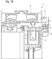
- a retraction device in which the driver 7 can be moved along a guide track 71 on the housing 6.
- two pins 70 are formed on the driver, which protrude on opposite sides and each engage in a slot or groove-shaped guide track 71.
- the driver 7 pivots at the angled end section 72 so that a decoupling between the projection 8 and a receptacle 75 on the driver 7 can take place, so that the sliding door 3 or 3 'can be moved detached from the retraction device. Only in an area shortly before the end position, for example 5 cm to 20 cm before the end position, is the projection 8 coupled to the driver 7 in order to apply appropriate braking forces to the sliding door 3 or 3 '.
- the driver 7 is connected to a damper 12, which is designed as a gas pressure damper and has a damper housing 13 into which a piston rod 14 engages and is guided over a piston.
- the damper housing 13 is fixed via a pin 15 on a holder 16 which is fixed on the front side of the housing 6.
- the housing 6 can be made from a profile, for example from an extruded aluminum profile, in which the holder 16 is fixed at the end via screws 17. As a result, the damper housing 13 is securely fixed at the end.
- the driver 7 with the receptacle 75 then protrudes slightly at a groove in the housing, so that the projection 8 can be coupled to the driver 7.
- the piston rod 14 is coupled to the driver 7 via a connecting element 20.
- the connecting element 20 has a receptacle 21 in order to fix the driver 7 at the damping direction and to guide it in a direction perpendicular to the damping direction.
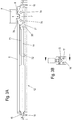
- the retraction device is shown in an end position which corresponds to the closed position of the sliding leaf 3 or 3 '.
- the driver 7 was moved from the angled end section 72 of the guide track to the opposite end of the guide track.
- the projection 8 engages in the receptacle 75 of the driver 7, a run-on bevel 76 being provided adjacent to the receptacle 75.
- This run-up bevel 76 has the function that the projection 8 can also be coupled to the driver 7 when the latter is already in the end position, for example because the gas pressure spring has already moved the driver 7 into the end position before the sliding door 3 or 3 'is actually in the end position, so that the projection 8 can then be moved along the run-up bevel 76 and pressed into a holder 9 against the force of a spring, in order to then snap into the receptacle 75.
- the mobility of the projection 7 perpendicular to the damping direction is shown schematically by the double arrow.
- the retraction device In the Figures 4A to 4C the retraction device is shown in more detail.
- the driver 7 rests against a stop 25 which is designed to be adjustable in order to be able to set the end position.
- the stop 25 has a threaded section which is screwed into a holder 18.
- the holder 18 is fixed by screws 19 on a profile of the sliding door 3 or 3 '.
- the holder 18 is also fixed to the housing 6 by means of screws 17.
- the end position of the driver 7 can be set via the adjustable stop 25.
- the driver 7 on the connecting element 20 is shown in detail.
- the connecting element 20 presses the driver through the damper 12 designed as a gas pressure spring into the end position against the stop 25.
- the driver 20 has a receptacle 21 into which a T-shaped section 77 of the driver 7 engages.
- the driver 7 is firmly coupled to the connecting element 20 in the damping direction, but can be pivoted perpendicular to the damping direction, for example when the driver 7 is moved along the angled end section of the guide track.
- the driver 7 is then formed from at least two parts, the driver having a guide part on which the pins 70 are arranged, and a receiving part on which the receptacle 75 is formed. These two parts are then mounted on one another in a displaceable or pivotable manner and are preferably biased into an initial position by a spring. As a result, the mobility of the driver 7 can also be used in order to lock a projection 8 over the run-on bevel 76 on the receptacle.
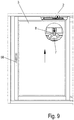
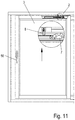
- FIG 6 a closed position is shown in which the fixed panel 4 and the sliding door 3 are arranged within the window frame 2.
- the projection 8 is spaced apart from the driver 7 in the vertical direction, so that they are not in operative connection. It is shown, however, that the projection 8 is biased towards the driver 7 by a spring 80 and the projection 8 is thus resiliently mounted on the holder 9 perpendicular to the damping direction.
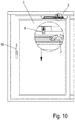
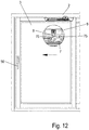
- a handle element 50 is first pivoted, as shown in FIG Figure 7 is shown.
- the sliding sash 3 is raised so that the projection 8 now engages in the receptacle 75 on the driver 7.
- the sliding sash 3 can now be moved in the opening direction, as shown in FIG Figure 8 can be seen, so that the gas pressure spring of the damper 12 is tensioned.
- the driver 7 has reached the angled end section 72 of the guide track and now releases the projection 8 so that the sliding sash 3 can be moved independently of the retraction device. in the In normal operation, the projection 8 can be coupled to the driver 7 during a closing movement.
- the projection 8 is resiliently mounted in a direction perpendicular to the damping direction.
- the damper is formed by a gas pressure damper, which serves both as an energy store and as a damper. It is of course also possible, instead of a gas pressure damper, to provide one or more springs which act on the driver 7 and apply the damping forces by one or more dampers which are designed independently of the springs. The use of a gas pressure damper, however, has the advantage that a particularly compact design is possible.
Landscapes
- Closing And Opening Devices For Wings, And Checks For Wings (AREA)
Priority Applications (1)
| Application Number | Priority Date | Filing Date | Title |
|---|---|---|---|
| PL15188749T PL3034752T3 (pl) | 2014-12-15 | 2015-10-07 | Urządzenie wciągające dla okna przesuwnego lub drzwi przesuwnych |
Applications Claiming Priority (1)
| Application Number | Priority Date | Filing Date | Title |
|---|---|---|---|
| DE102014118665.6A DE102014118665A1 (de) | 2014-12-15 | 2014-12-15 | Einzugsvorrichtung für ein Schiebefenster oder eine Schiebetür |
Publications (2)
| Publication Number | Publication Date |
|---|---|
| EP3034752A1 EP3034752A1 (de) | 2016-06-22 |
| EP3034752B1 true EP3034752B1 (de) | 2020-11-25 |
Family
ID=54266482
Family Applications (1)
| Application Number | Title | Priority Date | Filing Date |
|---|---|---|---|
| EP15188749.4A Active EP3034752B1 (de) | 2014-12-15 | 2015-10-07 | Einzugsvorrichtung für ein schiebefenster oder eine schiebetür |
Country Status (3)
| Country | Link |
|---|---|
| EP (1) | EP3034752B1 (pl) |
| DE (1) | DE102014118665A1 (pl) |
| PL (1) | PL3034752T3 (pl) |
Families Citing this family (7)
| Publication number | Priority date | Publication date | Assignee | Title |
|---|---|---|---|---|
| DE102017119772A1 (de) * | 2017-08-29 | 2019-02-28 | Hettich-Heinze Gmbh & Co. Kg | Einzugsvorrichtung zum Einziehen eines bewegbaren Teils eines Möbels oder Haushaltsgeräts in eine Endlage |
| PL71316Y1 (pl) * | 2017-12-19 | 2020-03-31 | Valcomp Spolka Z Ograniczona Odpowiedzialnoscia | Samo-regulowany aktywator |
| DE102019216524B4 (de) | 2019-07-31 | 2021-05-27 | Roto Frank Fenster- und Türtechnologie GmbH | Beschlaganordnung für einen parallelabstellbaren Flügel und Verschlussanordnung für eine Gebäudeöffnung |
| DE102019215332A1 (de) | 2019-10-07 | 2021-04-08 | W. Gessmann Gmbh | Lichtsignalvorrichtung für ein fahrerloses Transportsystem |
| CN113107296B (zh) * | 2021-05-13 | 2025-02-07 | 伦允强 | 一种用于扇体的导滑结构 |
| EP4446545A1 (de) | 2023-04-13 | 2024-10-16 | Gretsch-Unitas GmbH Baubeschläge | Einzugsdämpferbeschlag und tür- oder fensteranordnung |
| EP4647573A1 (de) | 2024-05-10 | 2025-11-12 | Gretsch-Unitas GmbH Baubeschläge | Einzugsvorrichtung und tür- oder fensteranordnung |
Citations (1)
| Publication number | Priority date | Publication date | Assignee | Title |
|---|---|---|---|---|
| DE202014001516U1 (de) * | 2014-02-20 | 2014-03-21 | Siegenia-Aubi Kg | Endlageeinzugs-und Endlagedämpfungsvorrichtung für einen verschiebbaren Flügel als Schiebeflügel oder verschiebbaren Hebe-Schiebeflügel eines Fensters oder einer Tür |
Family Cites Families (3)
| Publication number | Priority date | Publication date | Assignee | Title |
|---|---|---|---|---|
| DE10301121A1 (de) * | 2002-01-14 | 2003-07-24 | Johannes Krogull | Baueinheit |
| JP4577121B2 (ja) * | 2005-06-30 | 2010-11-10 | 中西金属工業株式会社 | 引戸用自動閉止装置 |
| JP5907693B2 (ja) * | 2011-03-14 | 2016-04-26 | 株式会社ニフコ | 可動体のアシスト装置 |
-
2014
- 2014-12-15 DE DE102014118665.6A patent/DE102014118665A1/de not_active Withdrawn
-
2015
- 2015-10-07 EP EP15188749.4A patent/EP3034752B1/de active Active
- 2015-10-07 PL PL15188749T patent/PL3034752T3/pl unknown
Patent Citations (1)
| Publication number | Priority date | Publication date | Assignee | Title |
|---|---|---|---|---|
| DE202014001516U1 (de) * | 2014-02-20 | 2014-03-21 | Siegenia-Aubi Kg | Endlageeinzugs-und Endlagedämpfungsvorrichtung für einen verschiebbaren Flügel als Schiebeflügel oder verschiebbaren Hebe-Schiebeflügel eines Fensters oder einer Tür |
Also Published As
| Publication number | Publication date |
|---|---|
| DE102014118665A1 (de) | 2016-06-16 |
| PL3034752T3 (pl) | 2021-04-19 |
| EP3034752A1 (de) | 2016-06-22 |
Similar Documents
| Publication | Publication Date | Title |
|---|---|---|
| EP3034752B1 (de) | Einzugsvorrichtung für ein schiebefenster oder eine schiebetür | |
| AT519593B1 (de) | Verriegelungsvorrichtung | |
| EP4144945B1 (de) | Schiebetürsystem, schiebetür und puffervorrichtung | |
| DE102016119515B4 (de) | Beschlag für eine Schiebetür und Schiebetüreinheit | |
| DE102008048994A1 (de) | Feststellvorrichtung für einen Flügel einer Tür | |
| DE202012002502U1 (de) | Vorrichtung zur Unterstützung und Erleichterung des Kipp-Öffnens und -Schließens für ein Fenster oder eine Tür | |
| WO2014019955A1 (de) | Absenkdichtung und gebäudeteil | |
| DE202014009249U1 (de) | Endlageeinzugs- und Endlagedämpfungsvorrichtung für einen verschiebbaren Flügel als Schiebeflügel oder verschiebbaren Hebe-Schiebeflügel eines Fensters oder einer Tür | |
| DE3437806A1 (de) | Schloss | |
| DE102016202377A1 (de) | Beschlaganordnung zur Anbindung eines schieb- und kippbaren Flügels | |
| EP2957697A1 (de) | Einzugsvorrichtung für Schiebetüren und Fenster oder Tür | |
| DE102012021008B3 (de) | Schnäpperschloss, insbesondere als Zusatzverriegelung einer Tür, eines Tors oder eines Fensters | |
| DE102019216524A1 (de) | Beschlaganordnung für einen parallelabstellbaren Flügel und Verschlussanordnung für eine Gebäudeöffnung | |
| DE102015000197A1 (de) | Sicherheitstürblatt | |
| DE102014106796A1 (de) | Einzugvorrichtung für Möbel | |
| EP2951374B1 (de) | Laufteil zum führen eines möbelteils in einer führungsrichtung über eine führungsschiene und möbelbeschlag | |
| EP2843169A1 (de) | Tragsystem für eine Schiebetür, sowie Schiebetür | |
| EP2816178A2 (de) | Beschlag für Fenster oder Türen | |
| DE102014216722B4 (de) | Steuerelement für eine Beschlaganordnung | |
| EP3192951B1 (de) | Beschlag für eine schiebetür, schiebetüreinheit, verfahren zum öffnen einer schiebetür und verfahren zum schliessen einer schiebetür | |
| EP3045076A1 (de) | Einzugsvorrichtung | |
| EP2835487A1 (de) | Klappeneinrichtung eines Gebäudes | |
| DE102011000295A1 (de) | Vorrichtung zum automatischen Schließen oder Öffnen einer Schiebetür | |
| EP3085876B1 (de) | Absenkdichtungsvorrichtung | |
| DE102009058922A1 (de) | Führung für einen Schiebeflügel |
Legal Events
| Date | Code | Title | Description |
|---|---|---|---|
| PUAI | Public reference made under article 153(3) epc to a published international application that has entered the european phase |
Free format text: ORIGINAL CODE: 0009012 |
|
| AK | Designated contracting states |
Kind code of ref document: A1 Designated state(s): AL AT BE BG CH CY CZ DE DK EE ES FI FR GB GR HR HU IE IS IT LI LT LU LV MC MK MT NL NO PL PT RO RS SE SI SK SM TR |
|
| AX | Request for extension of the european patent |
Extension state: BA ME |
|
| STAA | Information on the status of an ep patent application or granted ep patent |
Free format text: STATUS: REQUEST FOR EXAMINATION WAS MADE |
|
| 17P | Request for examination filed |
Effective date: 20161220 |
|
| RBV | Designated contracting states (corrected) |
Designated state(s): AL AT BE BG CH CY CZ DE DK EE ES FI FR GB GR HR HU IE IS IT LI LT LU LV MC MK MT NL NO PL PT RO RS SE SI SK SM TR |
|
| RAP1 | Party data changed (applicant data changed or rights of an application transferred) |
Owner name: HAUTAU GMBH |
|
| STAA | Information on the status of an ep patent application or granted ep patent |
Free format text: STATUS: EXAMINATION IS IN PROGRESS |
|
| 17Q | First examination report despatched |
Effective date: 20180828 |
|
| GRAP | Despatch of communication of intention to grant a patent |
Free format text: ORIGINAL CODE: EPIDOSNIGR1 |
|
| STAA | Information on the status of an ep patent application or granted ep patent |
Free format text: STATUS: GRANT OF PATENT IS INTENDED |
|
| INTG | Intention to grant announced |
Effective date: 20200605 |
|
| GRAS | Grant fee paid |
Free format text: ORIGINAL CODE: EPIDOSNIGR3 |
|
| GRAA | (expected) grant |
Free format text: ORIGINAL CODE: 0009210 |
|
| STAA | Information on the status of an ep patent application or granted ep patent |
Free format text: STATUS: THE PATENT HAS BEEN GRANTED |
|
| AK | Designated contracting states |
Kind code of ref document: B1 Designated state(s): AL AT BE BG CH CY CZ DE DK EE ES FI FR GB GR HR HU IE IS IT LI LT LU LV MC MK MT NL NO PL PT RO RS SE SI SK SM TR |
|
| REG | Reference to a national code |
Ref country code: GB Ref legal event code: FG4D Free format text: NOT ENGLISH |
|
| REG | Reference to a national code |
Ref country code: CH Ref legal event code: EP |
|
| REG | Reference to a national code |
Ref country code: DE Ref legal event code: R096 Ref document number: 502015013887 Country of ref document: DE |
|
| REG | Reference to a national code |
Ref country code: AT Ref legal event code: REF Ref document number: 1338494 Country of ref document: AT Kind code of ref document: T Effective date: 20201215 |
|
| REG | Reference to a national code |
Ref country code: IE Ref legal event code: FG4D Free format text: LANGUAGE OF EP DOCUMENT: GERMAN |
|
| REG | Reference to a national code |
Ref country code: NL Ref legal event code: MP Effective date: 20201125 |
|
| PG25 | Lapsed in a contracting state [announced via postgrant information from national office to epo] |
Ref country code: RS Free format text: LAPSE BECAUSE OF FAILURE TO SUBMIT A TRANSLATION OF THE DESCRIPTION OR TO PAY THE FEE WITHIN THE PRESCRIBED TIME-LIMIT Effective date: 20201125 Ref country code: FI Free format text: LAPSE BECAUSE OF FAILURE TO SUBMIT A TRANSLATION OF THE DESCRIPTION OR TO PAY THE FEE WITHIN THE PRESCRIBED TIME-LIMIT Effective date: 20201125 Ref country code: PT Free format text: LAPSE BECAUSE OF FAILURE TO SUBMIT A TRANSLATION OF THE DESCRIPTION OR TO PAY THE FEE WITHIN THE PRESCRIBED TIME-LIMIT Effective date: 20210325 Ref country code: NO Free format text: LAPSE BECAUSE OF FAILURE TO SUBMIT A TRANSLATION OF THE DESCRIPTION OR TO PAY THE FEE WITHIN THE PRESCRIBED TIME-LIMIT Effective date: 20210225 Ref country code: GR Free format text: LAPSE BECAUSE OF FAILURE TO SUBMIT A TRANSLATION OF THE DESCRIPTION OR TO PAY THE FEE WITHIN THE PRESCRIBED TIME-LIMIT Effective date: 20210226 |
|
| PG25 | Lapsed in a contracting state [announced via postgrant information from national office to epo] |
Ref country code: BG Free format text: LAPSE BECAUSE OF FAILURE TO SUBMIT A TRANSLATION OF THE DESCRIPTION OR TO PAY THE FEE WITHIN THE PRESCRIBED TIME-LIMIT Effective date: 20210225 Ref country code: LV Free format text: LAPSE BECAUSE OF FAILURE TO SUBMIT A TRANSLATION OF THE DESCRIPTION OR TO PAY THE FEE WITHIN THE PRESCRIBED TIME-LIMIT Effective date: 20201125 Ref country code: SE Free format text: LAPSE BECAUSE OF FAILURE TO SUBMIT A TRANSLATION OF THE DESCRIPTION OR TO PAY THE FEE WITHIN THE PRESCRIBED TIME-LIMIT Effective date: 20201125 Ref country code: IS Free format text: LAPSE BECAUSE OF FAILURE TO SUBMIT A TRANSLATION OF THE DESCRIPTION OR TO PAY THE FEE WITHIN THE PRESCRIBED TIME-LIMIT Effective date: 20210325 |
|
| REG | Reference to a national code |
Ref country code: LT Ref legal event code: MG9D |
|
| PG25 | Lapsed in a contracting state [announced via postgrant information from national office to epo] |
Ref country code: HR Free format text: LAPSE BECAUSE OF FAILURE TO SUBMIT A TRANSLATION OF THE DESCRIPTION OR TO PAY THE FEE WITHIN THE PRESCRIBED TIME-LIMIT Effective date: 20201125 |
|
| PG25 | Lapsed in a contracting state [announced via postgrant information from national office to epo] |
Ref country code: EE Free format text: LAPSE BECAUSE OF FAILURE TO SUBMIT A TRANSLATION OF THE DESCRIPTION OR TO PAY THE FEE WITHIN THE PRESCRIBED TIME-LIMIT Effective date: 20201125 Ref country code: CZ Free format text: LAPSE BECAUSE OF FAILURE TO SUBMIT A TRANSLATION OF THE DESCRIPTION OR TO PAY THE FEE WITHIN THE PRESCRIBED TIME-LIMIT Effective date: 20201125 Ref country code: SM Free format text: LAPSE BECAUSE OF FAILURE TO SUBMIT A TRANSLATION OF THE DESCRIPTION OR TO PAY THE FEE WITHIN THE PRESCRIBED TIME-LIMIT Effective date: 20201125 Ref country code: LT Free format text: LAPSE BECAUSE OF FAILURE TO SUBMIT A TRANSLATION OF THE DESCRIPTION OR TO PAY THE FEE WITHIN THE PRESCRIBED TIME-LIMIT Effective date: 20201125 Ref country code: RO Free format text: LAPSE BECAUSE OF FAILURE TO SUBMIT A TRANSLATION OF THE DESCRIPTION OR TO PAY THE FEE WITHIN THE PRESCRIBED TIME-LIMIT Effective date: 20201125 Ref country code: SK Free format text: LAPSE BECAUSE OF FAILURE TO SUBMIT A TRANSLATION OF THE DESCRIPTION OR TO PAY THE FEE WITHIN THE PRESCRIBED TIME-LIMIT Effective date: 20201125 |
|
| REG | Reference to a national code |
Ref country code: DE Ref legal event code: R097 Ref document number: 502015013887 Country of ref document: DE |
|
| PG25 | Lapsed in a contracting state [announced via postgrant information from national office to epo] |
Ref country code: DK Free format text: LAPSE BECAUSE OF FAILURE TO SUBMIT A TRANSLATION OF THE DESCRIPTION OR TO PAY THE FEE WITHIN THE PRESCRIBED TIME-LIMIT Effective date: 20201125 |
|
| PLBE | No opposition filed within time limit |
Free format text: ORIGINAL CODE: 0009261 |
|
| STAA | Information on the status of an ep patent application or granted ep patent |
Free format text: STATUS: NO OPPOSITION FILED WITHIN TIME LIMIT |
|
| PG25 | Lapsed in a contracting state [announced via postgrant information from national office to epo] |
Ref country code: NL Free format text: LAPSE BECAUSE OF FAILURE TO SUBMIT A TRANSLATION OF THE DESCRIPTION OR TO PAY THE FEE WITHIN THE PRESCRIBED TIME-LIMIT Effective date: 20201125 Ref country code: AL Free format text: LAPSE BECAUSE OF FAILURE TO SUBMIT A TRANSLATION OF THE DESCRIPTION OR TO PAY THE FEE WITHIN THE PRESCRIBED TIME-LIMIT Effective date: 20201125 |
|
| 26N | No opposition filed |
Effective date: 20210826 |
|
| PG25 | Lapsed in a contracting state [announced via postgrant information from national office to epo] |
Ref country code: SI Free format text: LAPSE BECAUSE OF FAILURE TO SUBMIT A TRANSLATION OF THE DESCRIPTION OR TO PAY THE FEE WITHIN THE PRESCRIBED TIME-LIMIT Effective date: 20201125 Ref country code: ES Free format text: LAPSE BECAUSE OF FAILURE TO SUBMIT A TRANSLATION OF THE DESCRIPTION OR TO PAY THE FEE WITHIN THE PRESCRIBED TIME-LIMIT Effective date: 20201125 |
|
| REG | Reference to a national code |
Ref country code: CH Ref legal event code: PL |
|
| PG25 | Lapsed in a contracting state [announced via postgrant information from national office to epo] |
Ref country code: IS Free format text: LAPSE BECAUSE OF FAILURE TO SUBMIT A TRANSLATION OF THE DESCRIPTION OR TO PAY THE FEE WITHIN THE PRESCRIBED TIME-LIMIT Effective date: 20210325 |
|
| GBPC | Gb: european patent ceased through non-payment of renewal fee |
Effective date: 20211007 |
|
| PG25 | Lapsed in a contracting state [announced via postgrant information from national office to epo] |
Ref country code: MC Free format text: LAPSE BECAUSE OF FAILURE TO SUBMIT A TRANSLATION OF THE DESCRIPTION OR TO PAY THE FEE WITHIN THE PRESCRIBED TIME-LIMIT Effective date: 20201125 |
|
| PG25 | Lapsed in a contracting state [announced via postgrant information from national office to epo] |
Ref country code: LU Free format text: LAPSE BECAUSE OF NON-PAYMENT OF DUE FEES Effective date: 20211007 Ref country code: GB Free format text: LAPSE BECAUSE OF NON-PAYMENT OF DUE FEES Effective date: 20211007 |
|
| PG25 | Lapsed in a contracting state [announced via postgrant information from national office to epo] |
Ref country code: LI Free format text: LAPSE BECAUSE OF NON-PAYMENT OF DUE FEES Effective date: 20211031 Ref country code: CH Free format text: LAPSE BECAUSE OF NON-PAYMENT OF DUE FEES Effective date: 20211031 |
|
| PG25 | Lapsed in a contracting state [announced via postgrant information from national office to epo] |
Ref country code: FR Free format text: LAPSE BECAUSE OF NON-PAYMENT OF DUE FEES Effective date: 20211031 |
|
| PG25 | Lapsed in a contracting state [announced via postgrant information from national office to epo] |
Ref country code: IE Free format text: LAPSE BECAUSE OF NON-PAYMENT OF DUE FEES Effective date: 20211007 |
|
| REG | Reference to a national code |
Ref country code: AT Ref legal event code: MM01 Ref document number: 1338494 Country of ref document: AT Kind code of ref document: T Effective date: 20211007 |
|
| PG25 | Lapsed in a contracting state [announced via postgrant information from national office to epo] |
Ref country code: AT Free format text: LAPSE BECAUSE OF NON-PAYMENT OF DUE FEES Effective date: 20211007 |
|
| PG25 | Lapsed in a contracting state [announced via postgrant information from national office to epo] |
Ref country code: HU Free format text: LAPSE BECAUSE OF FAILURE TO SUBMIT A TRANSLATION OF THE DESCRIPTION OR TO PAY THE FEE WITHIN THE PRESCRIBED TIME-LIMIT; INVALID AB INITIO Effective date: 20151007 |
|
| PG25 | Lapsed in a contracting state [announced via postgrant information from national office to epo] |
Ref country code: CY Free format text: LAPSE BECAUSE OF FAILURE TO SUBMIT A TRANSLATION OF THE DESCRIPTION OR TO PAY THE FEE WITHIN THE PRESCRIBED TIME-LIMIT Effective date: 20201125 |
|
| PG25 | Lapsed in a contracting state [announced via postgrant information from national office to epo] |
Ref country code: MK Free format text: LAPSE BECAUSE OF FAILURE TO SUBMIT A TRANSLATION OF THE DESCRIPTION OR TO PAY THE FEE WITHIN THE PRESCRIBED TIME-LIMIT Effective date: 20201125 |
|
| PG25 | Lapsed in a contracting state [announced via postgrant information from national office to epo] |
Ref country code: MT Free format text: LAPSE BECAUSE OF FAILURE TO SUBMIT A TRANSLATION OF THE DESCRIPTION OR TO PAY THE FEE WITHIN THE PRESCRIBED TIME-LIMIT Effective date: 20201125 |
|
| PGFP | Annual fee paid to national office [announced via postgrant information from national office to epo] |
Ref country code: DE Payment date: 20240126 Year of fee payment: 10 |
|
| PGFP | Annual fee paid to national office [announced via postgrant information from national office to epo] |
Ref country code: PL Payment date: 20241125 Year of fee payment: 11 |
|
| PGFP | Annual fee paid to national office [announced via postgrant information from national office to epo] |
Ref country code: IT Payment date: 20241031 Year of fee payment: 10 |
|
| PGFP | Annual fee paid to national office [announced via postgrant information from national office to epo] |
Ref country code: TR Payment date: 20250930 Year of fee payment: 11 |
|
| PGFP | Annual fee paid to national office [announced via postgrant information from national office to epo] |
Ref country code: BE Payment date: 20250916 Year of fee payment: 11 |