EP3034734A1 - Band für eine tür oder ein fenster - Google Patents
Band für eine tür oder ein fenster Download PDFInfo
- Publication number
- EP3034734A1 EP3034734A1 EP15196217.2A EP15196217A EP3034734A1 EP 3034734 A1 EP3034734 A1 EP 3034734A1 EP 15196217 A EP15196217 A EP 15196217A EP 3034734 A1 EP3034734 A1 EP 3034734A1
- Authority
- EP
- European Patent Office
- Prior art keywords
- hinge
- band
- frame
- wing
- door
- Prior art date
- Legal status (The legal status is an assumption and is not a legal conclusion. Google has not performed a legal analysis and makes no representation as to the accuracy of the status listed.)
- Granted
Links
Images



Classifications
-
- E—FIXED CONSTRUCTIONS
- E05—LOCKS; KEYS; WINDOW OR DOOR FITTINGS; SAFES
- E05D—HINGES OR SUSPENSION DEVICES FOR DOORS, WINDOWS OR WINGS
- E05D5/00—Construction of single parts, e.g. the parts for attachment
- E05D5/02—Parts for attachment, e.g. flaps
- E05D5/0215—Parts for attachment, e.g. flaps for attachment to profile members or the like
-
- E—FIXED CONSTRUCTIONS
- E05—LOCKS; KEYS; WINDOW OR DOOR FITTINGS; SAFES
- E05D—HINGES OR SUSPENSION DEVICES FOR DOORS, WINDOWS OR WINGS
- E05D7/00—Hinges or pivots of special construction
- E05D7/04—Hinges adjustable relative to the wing or the frame
- E05D7/0415—Hinges adjustable relative to the wing or the frame with adjusting drive means
-
- E—FIXED CONSTRUCTIONS
- E05—LOCKS; KEYS; WINDOW OR DOOR FITTINGS; SAFES
- E05D—HINGES OR SUSPENSION DEVICES FOR DOORS, WINDOWS OR WINGS
- E05D7/00—Hinges or pivots of special construction
- E05D7/04—Hinges adjustable relative to the wing or the frame
- E05D7/0415—Hinges adjustable relative to the wing or the frame with adjusting drive means
- E05D7/0423—Screw-and-nut mechanisms
-
- E—FIXED CONSTRUCTIONS
- E05—LOCKS; KEYS; WINDOW OR DOOR FITTINGS; SAFES
- E05D—HINGES OR SUSPENSION DEVICES FOR DOORS, WINDOWS OR WINGS
- E05D7/00—Hinges or pivots of special construction
- E05D7/04—Hinges adjustable relative to the wing or the frame
- E05D2007/0476—Pocket hinges
-
- E—FIXED CONSTRUCTIONS
- E05—LOCKS; KEYS; WINDOW OR DOOR FITTINGS; SAFES
- E05Y—INDEXING SCHEME ASSOCIATED WITH SUBCLASSES E05D AND E05F, RELATING TO CONSTRUCTION ELEMENTS, ELECTRIC CONTROL, POWER SUPPLY, POWER SIGNAL OR TRANSMISSION, USER INTERFACES, MOUNTING OR COUPLING, DETAILS, ACCESSORIES, AUXILIARY OPERATIONS NOT OTHERWISE PROVIDED FOR, APPLICATION THEREOF
- E05Y2201/00—Constructional elements; Accessories therefor
- E05Y2201/60—Suspension or transmission members; Accessories therefor
- E05Y2201/622—Suspension or transmission members elements
- E05Y2201/638—Cams; Ramps
-
- E—FIXED CONSTRUCTIONS
- E05—LOCKS; KEYS; WINDOW OR DOOR FITTINGS; SAFES
- E05Y—INDEXING SCHEME ASSOCIATED WITH SUBCLASSES E05D AND E05F, RELATING TO CONSTRUCTION ELEMENTS, ELECTRIC CONTROL, POWER SUPPLY, POWER SIGNAL OR TRANSMISSION, USER INTERFACES, MOUNTING OR COUPLING, DETAILS, ACCESSORIES, AUXILIARY OPERATIONS NOT OTHERWISE PROVIDED FOR, APPLICATION THEREOF
- E05Y2600/00—Mounting or coupling arrangements for elements provided for in this subclass
- E05Y2600/60—Mounting or coupling members; Accessories therefor
- E05Y2600/634—Spacers
-
- E—FIXED CONSTRUCTIONS
- E05—LOCKS; KEYS; WINDOW OR DOOR FITTINGS; SAFES
- E05Y—INDEXING SCHEME ASSOCIATED WITH SUBCLASSES E05D AND E05F, RELATING TO CONSTRUCTION ELEMENTS, ELECTRIC CONTROL, POWER SUPPLY, POWER SIGNAL OR TRANSMISSION, USER INTERFACES, MOUNTING OR COUPLING, DETAILS, ACCESSORIES, AUXILIARY OPERATIONS NOT OTHERWISE PROVIDED FOR, APPLICATION THEREOF
- E05Y2900/00—Application of doors, windows, wings or fittings thereof
- E05Y2900/10—Application of doors, windows, wings or fittings thereof for buildings or parts thereof
- E05Y2900/13—Type of wing
- E05Y2900/132—Doors
Definitions
- the invention relates to a band for a door or a window, which comprises a frame band and a wing band, which are each concealed in the frame or in the wing of the door or the window can be arranged, wherein the frame band has a fastening portion, which via a hinge with a Band tab is connected, and wherein the wing band has a mounting portion with a receptacle for the hinge strap and a clamping device for fixing the hinge strap.
- a similar band which is not intended for the hidden construction, for example, in the DE 102004042922 disclosed.
- a hinged by a hinge with a frame band hinge tab is inserted and fixed for attaching a door in a receptacle in a band pocket arranged on the wing.
- the attachment is made laterally by recesses on the hinge tab protruding clamping screws.
- the height adjustment via its own adjustment by means of sliding together inclined surfaces which can be actuated via screws and move a clamping plate in the recording of the belt bag.
- the entire receptacle within the band pocket is also laterally adjustable as a separate component by means of further screws. Overall, many components are needed, whereby the structure is susceptible to errors and the manufacturing cost is increased.
- the fixation and adjustment via different screws whereby the process of adjusting the door hinge is complicated.
- the DE 202006004198 U discloses a concealed hingeable hinge, which also has a height adjustment, in which the horizontal movement is translated by means of screws on inclined surfaces in a vertical movement.
- the adjustable receiving body must be used complicated in the respective recording and it requires additional retaining screws which secure the hinge in its final position. This structure is also complicated, costly to manufacture and error prone.
- Object of the present invention is to provide a concealed mountable tape which has a particularly simple and inexpensive construction, a fine adjustment of the height and preferably allowed in all directions, and in which the fixation of the tape and the height adjustment are made possible by the same component ,
- the clamping device comprises two arranged above and below the inserted hinge strap, slidable normal to the insertion direction of the hinge strap clamping jaws, wherein the jaws each have oblique control surfaces with slidable control surfaces of parallel to the insertion direction of the hinge strap by means of adjusting screws sliding adjustable wedges kinematically coupled, and wherein the receptacle for the hinge flap is formed in the attachment portion of the sash in the direction of movement of the jaws larger than the corresponding width of the hinge strap, so that the clamping device of the sash simultaneously serves for fixing and for height adjustment of the sash in relation to the frame band.
- the jaws When hanging a door or a window, the jaws are screwed far enough apart in the sash hinges, so that an insertion of the hinge band of the frame band is possible. After insertion, the weight of the door or window wing weighs on the hinge flap. By adjusting the upper clamping wedge the appropriate height can be adjusted. To secure the door or window sash against prying and final fix the band, the lower jaw is moved so far up that the hinge flap is held securely between the jaws. The adjustment of the height and fixation of the tape thus takes place per band with only two screws. As a result, components can be saved and the handling of the tape is significantly simplified.
- Another feature of the invention is that the oblique Control surfaces of the jaws and adjusting wedges each having parallel to the control surface extending undercuts and the respective jaws and adjusting wedges engage each other in the undercuts of the opposite part.
- a parallel to the insertion direction of the hinge strap by means of a screw displaceable soverstellelement is provided which protrudes with a projection with inserted hinge tab in a corresponding recess in the hinge tab, which on this projection, the insertion depth of the hinge flap is adjustable in the wing band.
- a secure lateral adjustment is realized in a simple manner. In many solutions of the prior art, the lateral adjustment takes place only by loosening the retaining screws and manually moving the entire door or window sash in the lateral direction within a certain margin. Due to the weight of the door or window sash and the associated difficult handling a precise adjustment to the millimeter by hand is difficult.
- the lateral adjustment element according to the invention allows an accurate and simple adjustment. The band can be adjusted exactly in two spatial directions.
- the lateral adjustment element including the associated adjusting screw is arranged in a corresponding recess in one of the clamping wedges, preferably in the upper clamping wedge.
- the entire height and lateral adjustment can be accommodated in a simple manner as a single assembly in the wing band.
- the receptacle for the hinge flap in this case can be made smaller in the direction of movement of the clamping wedges, since the projection of the soverstellelements together with the respective Jaw can be moved vertically out of the insertion path of the hinge strap.
- the hinge flap is designed as a separate part which is slidably connected to the hinge of the frame band normal to the door or window level by means of a set screw, whereby the contact pressure of the door or the window to the frame is adjustable.
- the band allows by providing this feature in a simple way, an adjustment in the third possible direction in space, allowing an accurate and easy adjustment of the contact pressure.
- connection between hinge tabs and the hinge of the frame band is formed by dovetailed recesses. This type of connection allows a secure hold of the hinge on the hinge, which also withstand the high loads that occur on the belt, while a safe and easy management of the hinge in the adjustment is possible.
- Wing bands on the frame and the frame band on the wing is possible.
- the band shown comprises a frame band 1, which is arranged concealed in the frame 3 of a door and a wing band 2, which is arranged concealed in the wing 4.
- Frame 3 and wing 4 are formed in this embodiment as hollow profiles.
- the frame band 1 is screwed with a mounting portion 5 on the frame 3 and has a joint 7 in the interior of the frame profile. At this joint 7, a hinge tab 6 is arranged, which is inserted into the wing band 2 and held in this.
- the wing band 2 is also connected via a mounting portion 8 with the wing 4 of the door.
- Fig. 2 the frame band 1 is shown in perspective view in detail.
- the fastening portion 5 of the frame strip 1 has bores 22, in which the fastening screws can be used for mounting on the frame 3.
- a joint 7 is connected to the attachment section.
- a hinge flap 6 is arranged, which is guided in a dovetail-shaped recess on the hinge 7 with a corresponding projection.
- the hinge flap 6 can be moved by the adjusting screw 21 in relation to the joint 7 within a certain range of motion, whereby the contact pressure of the door leaf is adjustable to the frame.
- a securing element 23 is mounted on the hinge 7.
- the hinge tab 6 also has on the upper and lower end side recesses 19, which serve to receive a projection 18 of a soverstellelements 17 (see Fig. 3 ). In principle, only one recess 19 is required, but in order to be able to use the band in a left or right hinged door, the recesses 19 are provided on both sides.
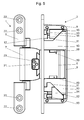
- Fig. 3 shows a side view of a possible embodiment of a sash strip 2 with removed housing cover.
- a receptacle 9 for the Recording of the hinge plate 6 is provided in the attachment portion 8 of the wing band 2 .
- jaws 10 are arranged, which are displaceable in the direction normal to the insertion direction of the hinge strap.
- the jaws 10 have inclined control surfaces 11 which cooperate with oblique control surfaces 12 of adjusting wedges 14.
- the respective control surfaces 11, 12 have undercuts 15, wherein the respective clamping jaws 10 and adjusting wedges 14 are arranged to overlap the mutual undercuts. If the set screws 13 are actuated, the respective adjusting wedge 14 shifts parallel to the direction of insertion of the hinge flap 6.
- the respective clamping wedge 10 is displaced in the vertical direction. Due to the undercuts there is a permanent kinematic coupling between the clamping wedges 10 and the adjusting wedges 14, so that the movement of the adjusting wedges 14 in both directions also means a movement of the clamping wedges 10 in both directions.
- a isverstellelement 17 is arranged in the attachment portion 8 of the wing hinge 2, which is displaceable parallel to the insertion direction of the hinge plate 6 by means of a screw 16.
- hinge tab protrudes a projection 18 of the soverstellelements 17 in the recess 19 in the hinge tab (see Fig. 5 ) and thus limits the possible insertion depth of the hinge and thus the lateral distance of the sash from the frame band.
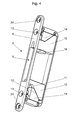
- a sash band 2 is shown.
- the holes 24 for the mounting screws are visible in this view, by means of which the wing band 2 is fixed to the wing 4.
- the soverstellelement 17 and the associated screw 16 is completely in a recess 20 (see Fig. 6 ) housed in a clamping wedge 10.
- This embodiment has the advantage that a lifting of the upper clamping wedge 10 also lifts the soverstellelement 17, whereby the projection 18 of the soverstellelements 17 can be moved out of the insertion path of the hinge strap 6.
- the length of the Recess 9 in the direction of movement of the clamping wedges 10 can therefore be made narrower than in the embodiment according to FIG Fig. 3 ,
- the recess 9 in the direction of movement of the clamping wedges must be slightly larger than the corresponding width of the hinge strap, so that a margin for the height adjustment is ever guaranteed.
- Fig. 5 shows the band according to the invention in the assembled state in which the hinge flap 6 is inserted into the wing band 2 and secured by means of the clamping wedges 10.
- An adjustment of the band in all three spatial directions is possible by adjusting the screws 13,16,21 in a simple manner and there are no additional fixing screws or devices needed to secure the band in its final adjusted position.
- Fig. 6 shows a rear view of the upper clamping wedge 10, adjusting wedge 14 and soverstellelement 17 according to the embodiment according to Fig. 4 or 5.
- the side adjustment 17 and the associated screw 16 are housed in a recess 20 in the clamping wedge 10 and are moved with this. Also visible are the undercuts 15 of the control surfaces 11, 12 of the clamping wedge 10 or Verstellkeils 14, which are arranged cross-over each other and thus ensure a permanent coupling of these two components.
Landscapes
- Engineering & Computer Science (AREA)
- Mechanical Engineering (AREA)
- Hinges (AREA)
Abstract
Description
- Die Erfindung betrifft ein Band für eine Tür oder ein Fenster, welches ein Rahmenband und ein Flügelband umfasst, die jeweils im Rahmen bzw. im Flügel der Tür oder des Fensters verdeckt anordenbar sind, wobei das Rahmenband einen Befestigungsabschnitt aufweist, der über ein Gelenk mit einem Bandlappen verbunden ist, und wobei das Flügelband einen Befestigungsabschnitt mit einer Aufnahme für den Bandlappen sowie eine Klemmeinrichtung zur Fixierung des Bandlappens aufweist.
- Ein ähnliches Band, welches jedoch nicht für die verdeckte Bauweise vorgesehen ist, ist beispielsweise in der
DE 102004042922 offenbart. Ein mittels eines Gelenks mit einem Rahmenband verbundener Bandlappen wird zur Befestigung einer Tür in eine Aufnahme in eine am Flügel angeordnete Bandtasche eingeschoben und befestigt. Die Befestigung erfolgt über seitlich durch Ausnehmungen am Bandlappen ragende Klemmschrauben. Die Höhenverstellung erfolgt über eine eigene Verstelleinrichtung mittels aneinander gleitender Schrägflächen, die über Stellschrauben betätigbar sind und eine Klemmplatte in der Aufnahme der Bandtasche verschieben. Die gesamte Aufnahme innerhalb der Bandtasche ist ebenfalls als separater Bauteil mittels weiterer Stellschrauben seitlich verstellbar. Insgesamt werden viele Bauteile benötigt, wodurch der Aufbau fehleranfällig ist und die Herstellungskosten erhöht sind. Die Fixierung und Einstellung erfolgt über verschiedene Schrauben, wodurch der Vorgang der Justierung des Türbandes kompliziert ist. - Die
DE 202006004198 U offenbart ein verdeckt einbaubares Scharnier, welches ebenfalls über eine Höhenverstellung verfügt, bei welcher die horizontale Bewegung mittels Stellschrauben über Schrägflächen in eine vertikale Bewegung übersetzt wird. Auch hier muss der verstellbare Aufnahmekörper kompliziert in der jeweiligen Aufnahme eingesetzt werden und es erfordert zusätzliche Halteschrauben, welche das Scharnier in seiner endgültigen Lage sichern. Auch dieser Aufbau ist kompliziert, kostenintensiv in der Herstellung und fehleranfällig. - Aufgabe der vorliegenden Erfindung ist es, ein verdeckt montierbares Band zu schaffen, welches einen besonders einfachen und kostengünstigen Aufbau aufweist, eine Feinjustierung der Höhe sowie bevorzugt in allen Raumrichtungen erlaubt, und bei welchem die Fixierung des Bandes sowie die Höhenverstellung durch das gleiche Bauteil ermöglicht werden.
- Diese Aufgabe wird erfindungsgemäß dadurch gelöst, dass die Klemmeinrichtung zwei oberhalb und unterhalb des eingeschobenen Bandlappens angeordnete, normal zur Einschubrichtung des Bandlappens verschiebbare Klemmbacken umfasst, wobei die Klemmbacken jeweils schräge Steuerflächen aufweisen, die mit schrägen Steuerflächen von parallel zur Einschubrichtung des Bandlappens mittels Stellschrauben verschiebbaren Verstellkeilen kinematisch koppelbar sind, und wobei die Aufnahme für den Bandlappen im Befestigungsabschnitt des Flügelbands in Bewegungsrichtung der Klemmbacken größer als die entsprechende Breite des Bandlappens ausgebildet ist, sodass die Klemmvorrichtung des Flügelbands gleichzeitig zur Fixierung sowie zur Höhenverstellung des Flügelbands in Relation zum Rahmenband dient. Beim Einhängen einer Tür oder eines Fensters werden in den Flügelbändern die Klemmbacken weit genug auseinander geschraubt, dass ein Einschieben des Bandlappens des Rahmenbands möglich ist. Nach dem Einschieben lastet das Gewicht des Tür- bzw. Fensterflügels auf dem Bandlappen. Durch Verstellen des oberen Klemmkeils kann die passende Höhe justiert werden. Um den Tür- bzw. Fensterflügel gegen Aushebeln zu sichern und das Band endgültig zu fixieren, wird der untere Klemmbacken soweit nach oben verschoben, dass der Bandlappen sicher zwischen den Klammbacken gehalten ist. Die Justierung der Höhe und Fixierung des Bandes erfolgt also je Band mit nur zwei Stellschrauben. Dadurch können Bauteile eingespart werden und die Handhabung des Bandes wird deutlich vereinfacht.
- Ein weiteres Merkmal der Erfindung ist es, dass die schrägen Steuerflächen der Klemmbacken und Verstellkeile jeweils parallel zur Steuerfläche verlaufende Hinterschneidungen aufweisen und die jeweiligen Klemmbacken und Verstellkeile gegenseitig in die Hinterschneidungen des gegenüberliegenden Teils eingreifen. Durch das gegenseitige Hintergreifen der jeweiligen Klemmbacken und Verstellkeile ergibt sich eine sichere Zwangsführung der Teile zueinander in beiden Bewegungsrichtungen. Die kinematische Kopplung zwischen Klemmbacken und Verstellkeilen ist also in jeder Stellung gegeben.
- Gemäß einem weiteren Merkmal der Erfindung ist es vorgesehen, dass im Flügelband ein parallel zur Einschubrichtung des Bandlappens mittels einer Stellschraube verschiebbares Seitenverstellelement vorgesehen ist, welches mit einem Vorsprung bei eingeschobenem Bandlappen in eine entsprechende Ausnehmung im Bandlappen ragt, wodurch über diesen Vorsprung die Einschubtiefe des Bandlappens in das Flügelband einstellbar ist. Eine sichere seitliche Verstellmöglichkeit wird so auf einfache Weise realisiert. Bei vielen Lösungen des Standes der Technik erfolgt die seitliche Verstellung lediglich durch Lösen der Halteschrauben und manuellem Verschieben des gesamten Tür- oder Fensterflügels in seitlicher Richtung innerhalb eines gewissen Spielraums. Aufgrund des Gewichts des Tür- bzw. Fensterflügels und der damit verbundenen erschwerten Handhabung ist ein auf Millimeter genaues Justieren von Hand nur schwer möglich. Das erfindungsgemäße Seitenverstellelement ermöglicht dagegen ein genaues und einfaches Verstellen. Das Band kann so in zwei Raumrichtungen genau eingestellt werden.
- Dabei ist es alternativ ein weiteres Merkmal der Erfindung, dass das Seitenverstellelement inklusive der zugehörigen Stellschraube in einer entsprechenden Ausnehmung in einem der Klemmkeile, vorzugsweise im oberen Klemmkeil angeordnet ist. Die gesamte Höhen- und Seitenverstellung kann so auf einfache Weise als eine einzige Baugruppe in dem Flügelband untergebracht werden. Ein weiterer Vorteil besteht darin, dass die Aufnahme für den Bandlappen in diesem Fall in Bewegungsrichtung der Klemmkeile kleiner ausgestaltet sein kann, da der Vorsprung des Seitenverstellelements gemeinsam mit der jeweiligen Klemmbacke vertikal aus dem Einschubweg des Bandlappens verschoben werden kann.
- Es ist ein weiteres Merkmal der vorliegenden Erfindung, dass der Bandlappen als separater Teil ausgeführt ist, welcher mit dem Gelenk des Rahmenbands normal zur Tür- bzw. Fensterebene mittels einer Stellschraube verschiebbar verbunden ist, wodurch der Anpressdruck der Tür bzw. des Fensters an den Rahmen einstellbar ist. Das Band ermöglicht durch Vorsehen dieses Merkmals auf einfache Weise auch eine Verstellmöglichkeit in die dritte mögliche Raumrichtung, was ein genaues und einfaches Einstellen des Anpressdrucks erlaubt.
- Schließlich ist es ein Merkmal der vorliegenden Erfindung, dass die Verbindung zwischen Bandlappen und dem Gelenk des Rahmenbandes durch schwalbenschwanzförmige Ausnehmungen bzw. gegengleiche Vorsprünge gebildet ist. Diese Art der Verbindung ermöglicht einen sicheren Halt des Bandlappens am Gelenk, welcher auch den hohen Belastungen, die am Band auftreten, standhält und gleichzeitig ist eine sichere und einfache Führung des Bandlappens in Verstellrichtung möglich.
- Es versteht sich für den Fachmann, dass die Begriffe Rahmenband und Flügelband relativ zu verstehen sind, sodass auch eine Montage des
- Flügelbands am Rahmen und des Rahmenbands am Flügel möglich ist.
- Die Erfindung wird nun im Detail mit Bezug auf die beiliegenden Zeichnungen beschrieben, wobei
-
Fig. 1 eine Schnittansicht eines Rahmen und Flügelprofils mit einem darin angeordneten Band zeigt, -
Fig. 2 eine perspektivische Ansicht eines Rahmenbands zeigt, -
Fig. 3 eine Seitenansicht einer möglichen Ausführungsform eines Flügelbands zeigt, -
Fig. 4 eine perspektivische Ansicht einer alternativen Ausführungsform eines Flügelbands zeigt, -
Fig. 5 eine Seitenansicht eines Rahmenbands und eines Flügelbands im zusammengesetzten Zustand zeigt und -
Fig. 6 eine perspektivische Detailansicht einer Klammbacke mit darin angeordnetem Seitenverstellelement zeigt. - Das in
Fig. 1 gezeigte Band umfasst ein Rahmenband 1, welches verdeckt im Rahmen 3 einer Tür angeordnet ist und ein Flügelband 2, welches verdeckt im Flügel 4 angeordnet ist. Rahmen 3 und Flügel 4 sind in dieser Ausführungsform als Hohlprofile ausgebildet. Das Rahmenband 1 wird mit einem Befestigungsabschnitt 5 am Rahmen 3 angeschraubt und weist im Inneren des Rahmenprofils ein Gelenk 7 auf. An diesem Gelenk 7 ist ein Bandlappen 6 angeordnet, welcher in das Flügelband 2 eingeschoben und in diesem gehalten ist. Das Flügelband 2 wird ebenfalls über einen Befestigungsabschnitt 8 mit dem Flügel 4 der Tür verbunden. - In
Fig. 2 ist das Rahmenband 1 in perspektivischer Ansicht im Detail dargestellt. Der Befestigungsabschnitt 5 des Rahmenbands 1 weist Bohrungen 22 auf, in welchen die Befestigungsschrauben zur Montage am Rahmen 3 einsetzbar sind. Mit dem Befestigungsabschnitt ist ein Gelenk 7 verbunden. Am freien Ende des Gelenks 7 ist ein Bandlappen 6 angeordnet, welcher in einer schwalbenschwanzförmigen Ausnehmung am Gelenk 7 mit einem entsprechenden Vorsprung geführt ist. Der Bandlappen 6 kann dabei durch die Stellschraube 21 in Relation zum Gelenk 7 innerhalb eines gewissen Bewegungsspielraums verschoben werden, wodurch der Anpressdruck des Türflügels an den Rahmen einstellbar ist. Zur Sicherung der Stellschraube 21 sowie als Wegbegrenzung für den Bandlappen 6 ist ein Sicherungselement 23 am Gelenk 7 montiert. Der Bandlappen 6 weist ferner an der oberen und unteren Stirnseite Ausnehmungen 19 auf, welche der Aufnahme eines Vorsprungs 18 eines Seitenverstellelements 17 dienen (sieheFig. 3 ). Prinzipiell wird nur eine Ausnehmung 19 benötigt, um das Band jedoch bei einer links oder rechts angeschlagenen Tür einsetzen zu können, werden die Ausnehmungen 19 an beiden Seiten vorgesehen. -
Fig. 3 zeigt eine Seitenansicht einer möglichen Ausführungsform eines Flügelbands 2 mit abgenommenem Gehäusedeckel. Im Befestigungsabschnitt 8 des Flügelbands 2 ist eine Aufnahme 9 für die Aufnahme des Bandlappens 6 vorgesehen. Oberhalb und unterhalb dieser Aufnahme 9 sind Klemmbacken 10 angeordnet, welche in Richtung normal zur Einschubrichtung des Bandlappens verschiebbar sind. Die Klemmbacken 10 weisen schräge Steuerflächen 11 auf, welche jeweils mit schrägen Steuerflächen 12 von Verstellkeilen 14 zusammenwirken. Die jeweiligen Steuerflächen 11,12 weisen Hinterschneidungen 15 auf, wobei die jeweiligen Klemmbacken 10 und Verstellkeile 14 die gegenseitigen Hinterschneidungen übergreifend angeordnet sind. Werden die Stellschrauben 13 betätigt, so verschiebt sich der jeweilige Verstellkeil 14 parallel zur Einschubrichtung des Bandlappens 6. Aufgrund des Aneinandergleitens der Steuerflächen 11,12 wird auch der jeweilige Klemmkeil 10 in vertikaler Richtung verschoben. Durch die Hinterschneidungen besteht eine permanente kinematische Kopplung zwischen den Klemmkeilen 10 und den Verstellkeilen 14, sodass die Bewegung der Verstellkeile 14 in beide Richtungen auch eine Bewegung der Klemmkeile 10 in beide Richtungen bedeutet. - Weiters ist in dem Befestigungsabschnitt 8 des Flügelbandes 2 ein Seitenverstellelement 17 angeordnet, welches mittels einer Stellschraube 16 parallel zur Einschubrichtung des Bandlappens 6 verschiebbar ist. Bei eingeschobenem Bandlappen ragt ein Vorsprung 18 des Seitenverstellelements 17 in die Ausnehmung 19 im Bandlappen (siehe
Fig. 5 ) und begrenzt somit die mögliche Einschubtiefe des Bandlappens und damit den seitlichen Abstand des Flügelbands vom Rahmenband. - In der
Fig. 4 ist eine alternative Ausführungsform eines Flügelbands 2 dargestellt. Am Befestigungsabschnitt 8 sind in dieser Ansicht auch die Bohrungen 24 für die Befestigungsschrauben ersichtlich, mittels welcher das Flügelband 2 am Flügel 4 befestigt wird. In dieser Ausführungsform ist das Seitenverstellelement 17 sowie die dazugehörige Stellschraube 16 vollständig in einer Ausnehmung 20 (sieheFig. 6 ) in einem Klemmkeil 10 untergebracht. Diese Ausführungsform hat den Vorteil, dass ein Anheben des oberen Klemmkeils 10 auch das Seitenverstellelement 17 mit anhebt, wodurch der Vorsprung 18 des Seitenverstellelements 17 aus dem Einschubweg des Bandlappens 6 bewegt werden kann. Die Länge der Ausnehmung 9 in Bewegungsrichtung der Klemmkeile 10 kann also schmaler ausgeführt werden, als in der Ausführungsform gemäßFig. 3 . Prinzipiell muss die Ausnehmung 9 in Bewegungsrichtung der Klemmkeile etwas größer sein als die korrespondierende Breite des Bandlappens, damit ein Spielraum für die Höhenverstellung überhaupt gewährleistet ist. -
Fig. 5 zeigt das erfindungsgemäße Band im zusammengesteckten Zustand, in welchem der Bandlappen 6 in das Flügelband 2 eingeschoben und mittels der Klemmkeile 10 gesichert ist. Ein Justieren des Bandes in allen drei Raumrichtungen ist durch Verstellen der Stellschrauben 13,16,21 in einfacher Weise möglich und es werden keine zusätzlichen Fixierschrauben oder Einrichtungen benötigt, um das Band in seiner endgültig justierten Lage zu sichern. -
Fig. 6 schließlich zeigt eine Rückansicht des oberen Klemmkeils 10, Verstellkeils 14 sowie Seitenverstellelement 17 gemäß der Ausführungsform nachFig. 4 bzw. 5. Das Seitenverstellelement 17 sowie die zugehörige Stellschraube 16 sind in einer Ausnehmung 20 im Klemmkeil 10 untergebracht und werden mit diesem mitbewegt. Auch zu sehen sind die Hinterschneidungen 15 der Steuerflächen 11, 12 des Klemmkeils 10 bzw. Verstellkeils 14, welche einander übergreifend angeordnet sind und somit eine permanente Kopplung dieser beiden Bauteile gewährleisten.
Claims (6)
- Band für eine Tür oder ein Fenster, welches ein Rahmenband (1) und ein Flügelband (2) umfasst, die jeweils im Rahmen (3) bzw. im Flügel (4) der Tür oder des Fensters verdeckt anordenbar sind, wobei das Rahmenband (1) einen Befestigungsabschnitt (5) aufweist, der über ein Gelenk (7) mit einem Bandlappen (6) verbunden ist, und wobei das Flügelband (2) einen Befestigungsabschnitt (8) mit einer Aufnahme (9) für den Bandlappen (6) sowie eine Klemmeinrichtung zur Fixierung des Bandlappens (6) aufweist, dadurch gekennzeichnet, dass die Klemmeinrichtung zwei oberhalb und unterhalb des eingeschobenen Bandlappens (6) angeordnete, normal zur Einschubrichtung des Bandlappens (6) verschiebbare Klemmbacken (10) umfasst, wobei die Klemmbacken (10) jeweils schräge Steuerflächen (11) aufweisen, die mit schrägen Steuerflächen (12) von parallel zur Einschubrichtung des Bandlappens (6) mittels Stellschrauben (13) verschiebbaren Verstellkeilen (14) kinematisch koppelbar sind, und wobei die Aufnahme (9) für den Bandlappen (6) im Befestigungsabschnitt (8) des Flügelbands (2) in Bewegungsrichtung der Klemmbacken (10) größer als die entsprechende Breite des Bandlappens (6) ausgebildet ist, sodass die Klemmvorrichtung des Flügelbands (2) gleichzeitig zur Fixierung sowie zur Höhenverstellung des Flügelbands (2) in Relation zum Rahmenband (1) dient.
- Band nach Anspruch 1, dadurch gekennzeichnet, dass die schrägen Steuerflächen (11,12) der Klemmbacken (10) und Verstellkeile (14) jeweils parallel zur Steuerfläche verlaufende Hinterschneidungen (15) aufweisen und die jeweiligen Klemmbacken (10) und Verstellkeile (14) gegenseitig in die Hinterschneidungen (15) des gegenüberliegenden Teils eingreifen.
- Band nach Anspruch 1 oder 2, dadurch gekennzeichnet, dass im Flügelband (2) ein parallel zur Einschubrichtung des Bandlappens (6) mittels einer Stellschraube (16) verschiebbares Seitenverstellelement (17) vorgesehen ist, welches mit einem Vorsprung (18) bei eingeschobenem Bandlappen (6) in eine entsprechende Ausnehmung (19) im Bandlappen (6) ragt, wodurch über diesen Vorsprung (18) die Einschubtiefe des Bandlappens (6) in das Flügelband (2) einstellbar ist.
- Band nach Anspruch 3, dadurch gekennzeichnet, dass das Seitenverstellelement (17) inklusive der zugehörigen Stellschraube (16) in einer entsprechenden Ausnehmung (20) in einem der Klemmkeile (10), vorzugsweise im oberen Klemmkeil angeordnet ist.
- Band nach einem der Ansprüche 1 bis 4, dadurch gekennzeichnet, dass der Bandlappen (6) als separater Teil ausgeführt ist, welcher mit dem Gelenk (7) des Rahmenbands (1) normal zur Tür- bzw. Fensterebene mittels einer Stellschraube (21) verschiebbar verbunden ist, wodurch der Anpressdruck der Tür bzw. des Fensters an den Rahmen (3) einstellbar ist.
- Band nach Anspruch 5, dadurch gekennzeichnet, dass die Verbindung zwischen Bandlappen (6) und dem Gelenk (7) des Rahmenbandes (1) durch schwalbenschwanzförmige Ausnehmungen bzw. gegengleiche Vorsprünge gebildet ist.
Applications Claiming Priority (1)
| Application Number | Priority Date | Filing Date | Title |
|---|---|---|---|
| ATGM50199/2014U AT14782U1 (de) | 2014-12-19 | 2014-12-19 | Band für eine Tür oder ein Fenster |
Publications (2)
| Publication Number | Publication Date |
|---|---|
| EP3034734A1 true EP3034734A1 (de) | 2016-06-22 |
| EP3034734B1 EP3034734B1 (de) | 2017-06-28 |
Family
ID=54705063
Family Applications (1)
| Application Number | Title | Priority Date | Filing Date |
|---|---|---|---|
| EP15196217.2A Active EP3034734B1 (de) | 2014-12-19 | 2015-11-25 | Band für eine tür oder ein fenster |
Country Status (2)
| Country | Link |
|---|---|
| EP (1) | EP3034734B1 (de) |
| AT (1) | AT14782U1 (de) |
Cited By (4)
| Publication number | Priority date | Publication date | Assignee | Title |
|---|---|---|---|---|
| EP3438388A1 (de) * | 2017-08-03 | 2019-02-06 | Roto Frank Ag | Montagehilfe |
| AT522457B1 (de) * | 2019-05-17 | 2020-11-15 | Blum Gmbh Julius | Möbelbeschlag |
| CN112502555A (zh) * | 2020-11-30 | 2021-03-16 | 义乌严冬电子商务有限公司 | 一种高端装备制造负载可自动调节保护的家具用铰链机构 |
| EP4245953A1 (de) * | 2022-03-15 | 2023-09-20 | "WALA" Spolka. z o.o. | Scharnieranordnung mit einer sperranordnung |
Families Citing this family (2)
| Publication number | Priority date | Publication date | Assignee | Title |
|---|---|---|---|---|
| AT15577U1 (de) * | 2016-10-19 | 2018-03-15 | Roto Frank Ag | Band für eine Tür oder ein Fenster |
| DE202023102012U1 (de) * | 2023-04-19 | 2023-05-08 | Kfv Karl Fliether Gmbh & Co. Kg | Band für eine Tür oder ein Fenster |
Citations (2)
| Publication number | Priority date | Publication date | Assignee | Title |
|---|---|---|---|---|
| DE102004042922B3 (de) | 2004-09-02 | 2005-08-11 | Simonswerk, Gmbh | Türband mit einem kammartigen Bandlappen |
| DE202006004198U1 (de) | 2006-03-16 | 2006-06-08 | Bartels Systembeschläge GmbH | Mehrachsenscharnier mit integrierter Höhenverstellhilfe für den bei geschlossener Tür nicht sichtbaren Einbau |
Family Cites Families (3)
| Publication number | Priority date | Publication date | Assignee | Title |
|---|---|---|---|---|
| DE20021406U1 (de) * | 2000-12-18 | 2002-05-02 | Dr. Hahn GmbH & Co. KG, 41189 Mönchengladbach | Bandanordnung für Türen, Fenster u.dgl. |
| DE102004033883B3 (de) * | 2004-07-13 | 2006-01-05 | Sfs Intec Holding Ag | Scharnier für stumpf einschlagende Türen |
| DE102006012051B4 (de) * | 2006-03-16 | 2013-12-19 | Bartels Systembeschläge GmbH | Bandaufnahme mit integrierter Höhenverstellung für Türzargen zur Aufnahme von Rahmenteilen zur dreidimensionalen Verstellung |
-
2014
- 2014-12-19 AT ATGM50199/2014U patent/AT14782U1/de not_active IP Right Cessation
-
2015
- 2015-11-25 EP EP15196217.2A patent/EP3034734B1/de active Active
Patent Citations (2)
| Publication number | Priority date | Publication date | Assignee | Title |
|---|---|---|---|---|
| DE102004042922B3 (de) | 2004-09-02 | 2005-08-11 | Simonswerk, Gmbh | Türband mit einem kammartigen Bandlappen |
| DE202006004198U1 (de) | 2006-03-16 | 2006-06-08 | Bartels Systembeschläge GmbH | Mehrachsenscharnier mit integrierter Höhenverstellhilfe für den bei geschlossener Tür nicht sichtbaren Einbau |
Cited By (5)
| Publication number | Priority date | Publication date | Assignee | Title |
|---|---|---|---|---|
| EP3438388A1 (de) * | 2017-08-03 | 2019-02-06 | Roto Frank Ag | Montagehilfe |
| AT522457B1 (de) * | 2019-05-17 | 2020-11-15 | Blum Gmbh Julius | Möbelbeschlag |
| AT522457A4 (de) * | 2019-05-17 | 2020-11-15 | Blum Gmbh Julius | Möbelbeschlag |
| CN112502555A (zh) * | 2020-11-30 | 2021-03-16 | 义乌严冬电子商务有限公司 | 一种高端装备制造负载可自动调节保护的家具用铰链机构 |
| EP4245953A1 (de) * | 2022-03-15 | 2023-09-20 | "WALA" Spolka. z o.o. | Scharnieranordnung mit einer sperranordnung |
Also Published As
| Publication number | Publication date |
|---|---|
| EP3034734B1 (de) | 2017-06-28 |
| AT14782U1 (de) | 2016-06-15 |
Similar Documents
| Publication | Publication Date | Title |
|---|---|---|
| EP3034734B1 (de) | Band für eine tür oder ein fenster | |
| EP3529440B1 (de) | Band für eine tür oder ein fenster | |
| WO2012159990A1 (de) | Scharnier | |
| DE102013113056B3 (de) | Aufnahmeelement für eine Stahlzarge und Stahlzarge damit | |
| EP3173559A1 (de) | Verstellbares türband | |
| EP3103948B1 (de) | Band für eine tür oder ein fenster | |
| DE102011050394A1 (de) | Beschlag für eine Schiebetür | |
| EP3690177A1 (de) | Profilverbinder mit drehgelenk | |
| EP3997292A1 (de) | Scharnier und system zum lösbaren verbinden einer tür mit einem rahmen | |
| EP2949844B1 (de) | Bandanordnung für Türen, Fenster oder dergleichen, mit einer Falzluftverstelleinrichtung | |
| EP2951374B1 (de) | Laufteil zum führen eines möbelteils in einer führungsrichtung über eine führungsschiene und möbelbeschlag | |
| CH711777B1 (de) | Türscharniervorrichtung umfassend eine Höhenverstelleinrichtung. | |
| EP0470601A1 (de) | Gerät zum Anbringen der Bohrungen zum Befestigen der Rahmenbandteile eines Fensters oder einer Türe | |
| DE202017105083U1 (de) | Türband mit Flügelstabilisierung | |
| DE2517367A1 (de) | Beschlag fuer kipp-schwenkfluegel von fenstern, tueren o. dgl. | |
| DE8603912U1 (de) | Möbel | |
| DE2138101B2 (de) | Oberlichtöffner mit zwei spiegelbildlich zwischen Blendrahmen und Flügel angeordneten Ausstellarmen | |
| AT511004A2 (de) | Einstellbarer rollenhalter für schiebetüren | |
| EP2385204A2 (de) | Verdeckt liegender Ecklagerbeschlag mit einem Niederhalter | |
| DE102012222210A1 (de) | Zur verdeckten Anordnung vorgesehenes Ecklager | |
| EP2578786A2 (de) | Halteeinrichtung für Tür- oder Fensterflügel | |
| DE102017128049A1 (de) | Auszugsvorrichtungen für Schubladen und dergleichen | |
| EP3438388A1 (de) | Montagehilfe | |
| DE20002853U1 (de) | Wandhalterung | |
| EP3325744A1 (de) | Führungsanordnung für eine schiebetür, schrankmöbel und verfahren zur demontage einer führungsanordnung für eine schiebetür |
Legal Events
| Date | Code | Title | Description |
|---|---|---|---|
| PUAI | Public reference made under article 153(3) epc to a published international application that has entered the european phase |
Free format text: ORIGINAL CODE: 0009012 |
|
| AK | Designated contracting states |
Kind code of ref document: A1 Designated state(s): AL AT BE BG CH CY CZ DE DK EE ES FI FR GB GR HR HU IE IS IT LI LT LU LV MC MK MT NL NO PL PT RO RS SE SI SK SM TR |
|
| AX | Request for extension of the european patent |
Extension state: BA ME |
|
| 17P | Request for examination filed |
Effective date: 20160919 |
|
| RBV | Designated contracting states (corrected) |
Designated state(s): AL AT BE BG CH CY CZ DE DK EE ES FI FR GB GR HR HU IE IS IT LI LT LU LV MC MK MT NL NO PL PT RO RS SE SI SK SM TR |
|
| GRAP | Despatch of communication of intention to grant a patent |
Free format text: ORIGINAL CODE: EPIDOSNIGR1 |
|
| INTG | Intention to grant announced |
Effective date: 20170201 |
|
| GRAS | Grant fee paid |
Free format text: ORIGINAL CODE: EPIDOSNIGR3 |
|
| GRAA | (expected) grant |
Free format text: ORIGINAL CODE: 0009210 |
|
| AK | Designated contracting states |
Kind code of ref document: B1 Designated state(s): AL AT BE BG CH CY CZ DE DK EE ES FI FR GB GR HR HU IE IS IT LI LT LU LV MC MK MT NL NO PL PT RO RS SE SI SK SM TR |
|
| REG | Reference to a national code |
Ref country code: GB Ref legal event code: FG4D Free format text: NOT ENGLISH |
|
| REG | Reference to a national code |
Ref country code: CH Ref legal event code: EP |
|
| REG | Reference to a national code |
Ref country code: AT Ref legal event code: REF Ref document number: 904987 Country of ref document: AT Kind code of ref document: T Effective date: 20170715 |
|
| REG | Reference to a national code |
Ref country code: IE Ref legal event code: FG4D Free format text: LANGUAGE OF EP DOCUMENT: GERMAN |
|
| REG | Reference to a national code |
Ref country code: DE Ref legal event code: R096 Ref document number: 502015001340 Country of ref document: DE |
|
| REG | Reference to a national code |
Ref country code: DE Ref legal event code: R082 Ref document number: 502015001340 Country of ref document: DE Representative=s name: PATENTANWAELTE JECK, FLECK & PARTNER MBB, DE Ref country code: DE Ref legal event code: R082 Ref document number: 502015001340 Country of ref document: DE Representative=s name: JECK - FLECK PATENTANWAELTE, DE |
|
| REG | Reference to a national code |
Ref country code: CH Ref legal event code: NV Representative=s name: AMMANN PATENTANWAELTE AG BERN, CH |
|
| PG25 | Lapsed in a contracting state [announced via postgrant information from national office to epo] |
Ref country code: GR Free format text: LAPSE BECAUSE OF FAILURE TO SUBMIT A TRANSLATION OF THE DESCRIPTION OR TO PAY THE FEE WITHIN THE PRESCRIBED TIME-LIMIT Effective date: 20170929 Ref country code: NO Free format text: LAPSE BECAUSE OF FAILURE TO SUBMIT A TRANSLATION OF THE DESCRIPTION OR TO PAY THE FEE WITHIN THE PRESCRIBED TIME-LIMIT Effective date: 20170928 Ref country code: LT Free format text: LAPSE BECAUSE OF FAILURE TO SUBMIT A TRANSLATION OF THE DESCRIPTION OR TO PAY THE FEE WITHIN THE PRESCRIBED TIME-LIMIT Effective date: 20170628 Ref country code: HR Free format text: LAPSE BECAUSE OF FAILURE TO SUBMIT A TRANSLATION OF THE DESCRIPTION OR TO PAY THE FEE WITHIN THE PRESCRIBED TIME-LIMIT Effective date: 20170628 Ref country code: FI Free format text: LAPSE BECAUSE OF FAILURE TO SUBMIT A TRANSLATION OF THE DESCRIPTION OR TO PAY THE FEE WITHIN THE PRESCRIBED TIME-LIMIT Effective date: 20170628 |
|
| REG | Reference to a national code |
Ref country code: NL Ref legal event code: MP Effective date: 20170628 |
|
| REG | Reference to a national code |
Ref country code: LT Ref legal event code: MG4D |
|
| PG25 | Lapsed in a contracting state [announced via postgrant information from national office to epo] |
Ref country code: RS Free format text: LAPSE BECAUSE OF FAILURE TO SUBMIT A TRANSLATION OF THE DESCRIPTION OR TO PAY THE FEE WITHIN THE PRESCRIBED TIME-LIMIT Effective date: 20170628 Ref country code: NL Free format text: LAPSE BECAUSE OF FAILURE TO SUBMIT A TRANSLATION OF THE DESCRIPTION OR TO PAY THE FEE WITHIN THE PRESCRIBED TIME-LIMIT Effective date: 20170628 Ref country code: LV Free format text: LAPSE BECAUSE OF FAILURE TO SUBMIT A TRANSLATION OF THE DESCRIPTION OR TO PAY THE FEE WITHIN THE PRESCRIBED TIME-LIMIT Effective date: 20170628 Ref country code: BG Free format text: LAPSE BECAUSE OF FAILURE TO SUBMIT A TRANSLATION OF THE DESCRIPTION OR TO PAY THE FEE WITHIN THE PRESCRIBED TIME-LIMIT Effective date: 20170928 Ref country code: SE Free format text: LAPSE BECAUSE OF FAILURE TO SUBMIT A TRANSLATION OF THE DESCRIPTION OR TO PAY THE FEE WITHIN THE PRESCRIBED TIME-LIMIT Effective date: 20170628 |
|
| PG25 | Lapsed in a contracting state [announced via postgrant information from national office to epo] |
Ref country code: RO Free format text: LAPSE BECAUSE OF FAILURE TO SUBMIT A TRANSLATION OF THE DESCRIPTION OR TO PAY THE FEE WITHIN THE PRESCRIBED TIME-LIMIT Effective date: 20170628 Ref country code: EE Free format text: LAPSE BECAUSE OF FAILURE TO SUBMIT A TRANSLATION OF THE DESCRIPTION OR TO PAY THE FEE WITHIN THE PRESCRIBED TIME-LIMIT Effective date: 20170628 Ref country code: CZ Free format text: LAPSE BECAUSE OF FAILURE TO SUBMIT A TRANSLATION OF THE DESCRIPTION OR TO PAY THE FEE WITHIN THE PRESCRIBED TIME-LIMIT Effective date: 20170628 Ref country code: SK Free format text: LAPSE BECAUSE OF FAILURE TO SUBMIT A TRANSLATION OF THE DESCRIPTION OR TO PAY THE FEE WITHIN THE PRESCRIBED TIME-LIMIT Effective date: 20170628 |
|
| PG25 | Lapsed in a contracting state [announced via postgrant information from national office to epo] |
Ref country code: ES Free format text: LAPSE BECAUSE OF FAILURE TO SUBMIT A TRANSLATION OF THE DESCRIPTION OR TO PAY THE FEE WITHIN THE PRESCRIBED TIME-LIMIT Effective date: 20170628 Ref country code: IS Free format text: LAPSE BECAUSE OF FAILURE TO SUBMIT A TRANSLATION OF THE DESCRIPTION OR TO PAY THE FEE WITHIN THE PRESCRIBED TIME-LIMIT Effective date: 20171028 Ref country code: SM Free format text: LAPSE BECAUSE OF FAILURE TO SUBMIT A TRANSLATION OF THE DESCRIPTION OR TO PAY THE FEE WITHIN THE PRESCRIBED TIME-LIMIT Effective date: 20170628 Ref country code: PL Free format text: LAPSE BECAUSE OF FAILURE TO SUBMIT A TRANSLATION OF THE DESCRIPTION OR TO PAY THE FEE WITHIN THE PRESCRIBED TIME-LIMIT Effective date: 20170628 Ref country code: IT Free format text: LAPSE BECAUSE OF FAILURE TO SUBMIT A TRANSLATION OF THE DESCRIPTION OR TO PAY THE FEE WITHIN THE PRESCRIBED TIME-LIMIT Effective date: 20170628 |
|
| REG | Reference to a national code |
Ref country code: DE Ref legal event code: R097 Ref document number: 502015001340 Country of ref document: DE |
|
| PG25 | Lapsed in a contracting state [announced via postgrant information from national office to epo] |
Ref country code: DK Free format text: LAPSE BECAUSE OF FAILURE TO SUBMIT A TRANSLATION OF THE DESCRIPTION OR TO PAY THE FEE WITHIN THE PRESCRIBED TIME-LIMIT Effective date: 20170628 |
|
| PLBE | No opposition filed within time limit |
Free format text: ORIGINAL CODE: 0009261 |
|
| STAA | Information on the status of an ep patent application or granted ep patent |
Free format text: STATUS: NO OPPOSITION FILED WITHIN TIME LIMIT |
|
| 26N | No opposition filed |
Effective date: 20180329 |
|
| PG25 | Lapsed in a contracting state [announced via postgrant information from national office to epo] |
Ref country code: MC Free format text: LAPSE BECAUSE OF FAILURE TO SUBMIT A TRANSLATION OF THE DESCRIPTION OR TO PAY THE FEE WITHIN THE PRESCRIBED TIME-LIMIT Effective date: 20170628 |
|
| PG25 | Lapsed in a contracting state [announced via postgrant information from national office to epo] |
Ref country code: SI Free format text: LAPSE BECAUSE OF FAILURE TO SUBMIT A TRANSLATION OF THE DESCRIPTION OR TO PAY THE FEE WITHIN THE PRESCRIBED TIME-LIMIT Effective date: 20170628 Ref country code: LU Free format text: LAPSE BECAUSE OF NON-PAYMENT OF DUE FEES Effective date: 20171125 |
|
| REG | Reference to a national code |
Ref country code: FR Ref legal event code: ST Effective date: 20180731 Ref country code: BE Ref legal event code: MM Effective date: 20171130 |
|
| REG | Reference to a national code |
Ref country code: IE Ref legal event code: MM4A |
|
| PG25 | Lapsed in a contracting state [announced via postgrant information from national office to epo] |
Ref country code: MT Free format text: LAPSE BECAUSE OF FAILURE TO SUBMIT A TRANSLATION OF THE DESCRIPTION OR TO PAY THE FEE WITHIN THE PRESCRIBED TIME-LIMIT Effective date: 20170628 |
|
| PG25 | Lapsed in a contracting state [announced via postgrant information from national office to epo] |
Ref country code: FR Free format text: LAPSE BECAUSE OF NON-PAYMENT OF DUE FEES Effective date: 20171130 Ref country code: IE Free format text: LAPSE BECAUSE OF NON-PAYMENT OF DUE FEES Effective date: 20171125 |
|
| PG25 | Lapsed in a contracting state [announced via postgrant information from national office to epo] |
Ref country code: BE Free format text: LAPSE BECAUSE OF NON-PAYMENT OF DUE FEES Effective date: 20171130 |
|
| PG25 | Lapsed in a contracting state [announced via postgrant information from national office to epo] |
Ref country code: HU Free format text: LAPSE BECAUSE OF FAILURE TO SUBMIT A TRANSLATION OF THE DESCRIPTION OR TO PAY THE FEE WITHIN THE PRESCRIBED TIME-LIMIT; INVALID AB INITIO Effective date: 20151125 |
|
| PG25 | Lapsed in a contracting state [announced via postgrant information from national office to epo] |
Ref country code: CY Free format text: LAPSE BECAUSE OF FAILURE TO SUBMIT A TRANSLATION OF THE DESCRIPTION OR TO PAY THE FEE WITHIN THE PRESCRIBED TIME-LIMIT Effective date: 20170628 |
|
| PG25 | Lapsed in a contracting state [announced via postgrant information from national office to epo] |
Ref country code: MK Free format text: LAPSE BECAUSE OF FAILURE TO SUBMIT A TRANSLATION OF THE DESCRIPTION OR TO PAY THE FEE WITHIN THE PRESCRIBED TIME-LIMIT Effective date: 20170628 |
|
| PG25 | Lapsed in a contracting state [announced via postgrant information from national office to epo] |
Ref country code: TR Free format text: LAPSE BECAUSE OF FAILURE TO SUBMIT A TRANSLATION OF THE DESCRIPTION OR TO PAY THE FEE WITHIN THE PRESCRIBED TIME-LIMIT Effective date: 20170628 |
|
| PG25 | Lapsed in a contracting state [announced via postgrant information from national office to epo] |
Ref country code: PT Free format text: LAPSE BECAUSE OF FAILURE TO SUBMIT A TRANSLATION OF THE DESCRIPTION OR TO PAY THE FEE WITHIN THE PRESCRIBED TIME-LIMIT Effective date: 20170628 |
|
| PG25 | Lapsed in a contracting state [announced via postgrant information from national office to epo] |
Ref country code: AL Free format text: LAPSE BECAUSE OF FAILURE TO SUBMIT A TRANSLATION OF THE DESCRIPTION OR TO PAY THE FEE WITHIN THE PRESCRIBED TIME-LIMIT Effective date: 20170628 |
|
| GBPC | Gb: european patent ceased through non-payment of renewal fee |
Effective date: 20191125 |
|
| PG25 | Lapsed in a contracting state [announced via postgrant information from national office to epo] |
Ref country code: GB Free format text: LAPSE BECAUSE OF NON-PAYMENT OF DUE FEES Effective date: 20191125 |
|
| PGFP | Annual fee paid to national office [announced via postgrant information from national office to epo] |
Ref country code: CH Payment date: 20201022 Year of fee payment: 6 Ref country code: AT Payment date: 20201201 Year of fee payment: 6 |
|
| REG | Reference to a national code |
Ref country code: CH Ref legal event code: PL |
|
| REG | Reference to a national code |
Ref country code: AT Ref legal event code: MM01 Ref document number: 904987 Country of ref document: AT Kind code of ref document: T Effective date: 20211125 |
|
| PG25 | Lapsed in a contracting state [announced via postgrant information from national office to epo] |
Ref country code: LI Free format text: LAPSE BECAUSE OF NON-PAYMENT OF DUE FEES Effective date: 20211130 Ref country code: CH Free format text: LAPSE BECAUSE OF NON-PAYMENT OF DUE FEES Effective date: 20211130 Ref country code: AT Free format text: LAPSE BECAUSE OF NON-PAYMENT OF DUE FEES Effective date: 20211125 |
|
| PGFP | Annual fee paid to national office [announced via postgrant information from national office to epo] |
Ref country code: DE Payment date: 20251118 Year of fee payment: 11 |