EP3034367B1 - Kühlvorrichtung für ein funktionelles element eines fahrzeugs, und mit einer solchen vorrichtung ausgestattetes fahrzeug - Google Patents
Kühlvorrichtung für ein funktionelles element eines fahrzeugs, und mit einer solchen vorrichtung ausgestattetes fahrzeug Download PDFInfo
- Publication number
- EP3034367B1 EP3034367B1 EP15194581.3A EP15194581A EP3034367B1 EP 3034367 B1 EP3034367 B1 EP 3034367B1 EP 15194581 A EP15194581 A EP 15194581A EP 3034367 B1 EP3034367 B1 EP 3034367B1
- Authority
- EP
- European Patent Office
- Prior art keywords
- air
- vehicle
- scoop
- functional element
- manifold
- Prior art date
- Legal status (The legal status is an assumption and is not a legal conclusion. Google has not performed a legal analysis and makes no representation as to the accuracy of the status listed.)
- Active
Links
- 238000001816 cooling Methods 0.000 title claims description 35
- 230000001681 protective effect Effects 0.000 claims description 10
- 230000003190 augmentative effect Effects 0.000 claims description 6
- 238000005192 partition Methods 0.000 description 22
- 238000004519 manufacturing process Methods 0.000 description 7
- 239000000463 material Substances 0.000 description 5
- 238000000465 moulding Methods 0.000 description 4
- 230000002349 favourable effect Effects 0.000 description 3
- 230000035515 penetration Effects 0.000 description 3
- 238000006073 displacement reaction Methods 0.000 description 2
- 230000000694 effects Effects 0.000 description 2
- 230000000750 progressive effect Effects 0.000 description 2
- OKTJSMMVPCPJKN-UHFFFAOYSA-N Carbon Chemical compound [C] OKTJSMMVPCPJKN-UHFFFAOYSA-N 0.000 description 1
- 241001080024 Telles Species 0.000 description 1
- 230000001133 acceleration Effects 0.000 description 1
- 230000005540 biological transmission Effects 0.000 description 1
- 229910052799 carbon Inorganic materials 0.000 description 1
- 230000005465 channeling Effects 0.000 description 1
- 238000002485 combustion reaction Methods 0.000 description 1
- 238000009792 diffusion process Methods 0.000 description 1
- 238000005265 energy consumption Methods 0.000 description 1
- 238000005516 engineering process Methods 0.000 description 1
- 235000021183 entrée Nutrition 0.000 description 1
- 239000012530 fluid Substances 0.000 description 1
- 230000002093 peripheral effect Effects 0.000 description 1
- 239000000725 suspension Substances 0.000 description 1
- 238000009423 ventilation Methods 0.000 description 1
- XLYOFNOQVPJJNP-UHFFFAOYSA-N water Substances O XLYOFNOQVPJJNP-UHFFFAOYSA-N 0.000 description 1
Images

Classifications
-
- B—PERFORMING OPERATIONS; TRANSPORTING
- B60—VEHICLES IN GENERAL
- B60T—VEHICLE BRAKE CONTROL SYSTEMS OR PARTS THEREOF; BRAKE CONTROL SYSTEMS OR PARTS THEREOF, IN GENERAL; ARRANGEMENT OF BRAKING ELEMENTS ON VEHICLES IN GENERAL; PORTABLE DEVICES FOR PREVENTING UNWANTED MOVEMENT OF VEHICLES; VEHICLE MODIFICATIONS TO FACILITATE COOLING OF BRAKES
- B60T5/00—Vehicle modifications to facilitate cooling of brakes
-
- F—MECHANICAL ENGINEERING; LIGHTING; HEATING; WEAPONS; BLASTING
- F16—ENGINEERING ELEMENTS AND UNITS; GENERAL MEASURES FOR PRODUCING AND MAINTAINING EFFECTIVE FUNCTIONING OF MACHINES OR INSTALLATIONS; THERMAL INSULATION IN GENERAL
- F16D—COUPLINGS FOR TRANSMITTING ROTATION; CLUTCHES; BRAKES
- F16D65/00—Parts or details
- F16D65/78—Features relating to cooling
- F16D65/84—Features relating to cooling for disc brakes
- F16D65/847—Features relating to cooling for disc brakes with open cooling system, e.g. cooled by air
-
- B—PERFORMING OPERATIONS; TRANSPORTING
- B62—LAND VEHICLES FOR TRAVELLING OTHERWISE THAN ON RAILS
- B62D—MOTOR VEHICLES; TRAILERS
- B62D35/00—Vehicle bodies characterised by streamlining
- B62D35/02—Streamlining the undersurfaces
-
- Y—GENERAL TAGGING OF NEW TECHNOLOGICAL DEVELOPMENTS; GENERAL TAGGING OF CROSS-SECTIONAL TECHNOLOGIES SPANNING OVER SEVERAL SECTIONS OF THE IPC; TECHNICAL SUBJECTS COVERED BY FORMER USPC CROSS-REFERENCE ART COLLECTIONS [XRACs] AND DIGESTS
- Y02—TECHNOLOGIES OR APPLICATIONS FOR MITIGATION OR ADAPTATION AGAINST CLIMATE CHANGE
- Y02T—CLIMATE CHANGE MITIGATION TECHNOLOGIES RELATED TO TRANSPORTATION
- Y02T10/00—Road transport of goods or passengers
- Y02T10/80—Technologies aiming to reduce greenhouse gasses emissions common to all road transportation technologies
- Y02T10/88—Optimized components or subsystems, e.g. lighting, actively controlled glasses
Definitions
- the present invention relates generally to the field of the automobile, and more specifically relates to a cooling device of a functional element of a vehicle and a vehicle equipped with such a device.
- braking systems convert the mechanical energy of braking into heat energy that must be evacuated in order to keep the braking system components operational.
- Discs and platelets which essentially constitute the functional units of the braking systems require special treatment of their cooling means. For this purpose, it is customary to ventilate the brake discs, or even to use high-temperature resistant materials, such as carbon for example, which remains expensive in its manufacture. This technology is often reserved for private vehicles in their use, such as competition vehicles.
- the need for lightening is increasing so that the size of the disks tends to be optimized.
- the reduction of the size of the disks is inversely proportional to the faculty of evacuation of the heat energy resulting from braking.
- Air deflectors are known at the bottom of a front bumper of the vehicle as well as semi-open air ducts to create an air flow path in the direction of the brake discs to be cooled. downstream, depending on the direction of flow of the air. Such a flow path is defined so that it crosses the tire in which the disk to be cooled, thereby reducing the desired cooling effect.
- the cooling device is of optimized design in that it is compact in order not to degrade the coefficient of penetration into the air of the vehicle in operation, while improving the speed of air flow and as the direction of an air flow to the functional element to be cooled.
- the protection screen comprises an increased cooling means of a functional element to be cooled allowing, during its movement, to capture the air and to generate a flow of air of increased intensity directed towards said functional element at cool.
- Said increased cooling means comprises an air scoop disposed in the air collector, said scoop comprising vertical partitions connected to each other by means of at least one inclined transverse partition.
- the underbody protection screen may be located in the extension of a front shield of the vehicle, such a shield being known to delimit a front end portion of the vehicle. Such an air flow allows an increased heat exchange between the air and the functional element to be cooled.
- the invention also relates to a vehicle comprising a cooling device according to any one of the above-mentioned features, wherein said functional element to be cooled is a vehicle safety device, such as a disc of a braking device, said increased cooling means extending vertically to the right of the disc of the braking device.
- a vehicle safety device such as a disc of a braking device
- the motor vehicle comprises in the front part of the base which comprises a cooling device 1 consisting in particular of at least one shield 2 extending substantially to the front heat exchangers heat exchanger.
- a cooling device 1 consisting in particular of at least one shield 2 extending substantially to the front heat exchangers heat exchanger.
- Such a screen 2 also prevents splashing water and chippings to hit the exchangers while allowing a channeling of air both through exchangers and under vehicle, thereby improving the aerodynamics of the vehicle and its protection.
- the protection screen 2 is located at the extension of a shield delimiting a front end portion of the vehicle, in that its front peripheral portion cooperates in complementarity with the front bumper.
- the screen 2 is substantially in the form of a plate made for example by molding a plastic material, the shape of which resumes approximately that of a shield that extends longitudinally towards the rear of the vehicle, from below.
- the shield extends substantially in a vertical direction to the vehicle to delineate a front end portion 3 of the vehicle.
- the lower part of the shield can cooperate directly with the front periphery area of the screen 2 of protection.
- the outer periphery zone of the protection screen 2 advantageously follows the curved profile of the shield.
- the protection screen 2 comprises an increased cooling means 5 of said functional element 4 to be cooled, which makes it possible, during the movement of the vehicle, to capture the air from the front part of the vehicle and to generate a directed air flow F of increased intensity.
- to the said functional element 4 to be cooled On the extension of the screen 2 is disposed a mechanical unit specific to the vehicle including a transmission device for mechanically connecting the motor to a wheel not shown, a suspension device connecting the vehicle body to a wheel, and a braking device composed in part of a disc 13 and platelets 14 held by stirrups.
- the underbody protection screen 2 is then disposed before the front wheel axle, in the longitudinal direction to the vehicle.
- the protective screen is disposed towards the rear of the vehicle, but forward the rear axle, in a longitudinal direction to the vehicle.
- the cooling device 1 makes it possible to cool the disc of the braking system of the vehicle.
- Screen 2 includes an augmented cooling means for forced cooling of the brake disc.
- Each disc of a braking system can be cooled by the device of the invention.
- a screen 2 may contain several increased cooling means, depending on the number of disks to be cooled,
- said augmented cooling means 5 comprises an air collector 6 in which a scoop 10 of air is disposed.
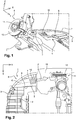
- the collector 6 is arranged on the screen 2 in such a way that the disc 13 can be cooled during the movement of the vehicle, by means of an air flow represented by the arrow F on the Figures 1 and 2 .
- Such an air flow is different from the traditional air flows generated by a closed duct to bring air from the front face 3 to an area close to the wheel, in that the flow of air is increased and directed to a particular area in which there is an element to be cooled, such as a brake disk.
- the collector 6 comprises a scoop 10.
- the collector 6 may have a substantially U-shaped cross section, and consequently have an open downwardly.
- the collector 6 is thus delimited by lateral walls 7 and 8 connected to one another by a bottom wall 9, as is made visible to the figures 2 and 3 .
- Such a collector 6 can come from the material of the screen 2 of protection, by means of a molding operation of a plastic material.
- the collector 6 may be of scalable section in that the height of the side walls 7 and 8 evolve as is visible in the figures.
- the flow path thus formed by the collector 6 comprises an inlet whose height is less than the height of its outlet.
- the walls 7 and 8 are substantially identical to one another in height along the air flow path, with a minimum height at the manifold inlet and a maximum height at the inlet. his exit.
- the longitudinal axis x extends from the front to the rear and the vertical axis z extends as its name indicates vertically to the vehicle, the outlet of the manifold 6 is shifted transversely to the inside relative to the disk 13 to be cooled, as is made visible on the figure 3 .
- the outlet of the manifold 6 is located below the brake pads 14, so that the region of the disk which rises rapidly in temperature due to the clamping of the plates is cooled.
- said augmented cooling means which comprises at approximately the last quarter of the air flow path of the collector 6, between the side walls 7 and 8, a scoop 10.
- the scoop 10 comprises vertical partitions 11, here five in number, arranged parallel to each other.
- the vertical partitions 11 may also be parallel to the side walls 7 and 8 of the collector 6.
- Each of the vertical partitions 11 is connected to a partition which is directly adjacent thereto via an inclined transverse partition 12.
- the inclined transverse partition 12 is single and integrally connects each of the vertical partitions to one another.
- the transverse partition 12 is inclined relative to the bottom 9 of the collector 6.
- the vertical partitions 11 extend perpendicular to the transverse partition 12 inclined, projecting vertically from the upper and lower faces of the transverse partition 12.
- the scoop 10 forms with the collector 6 of the air flow channels adjacent to each other.
- the adjacent channels Given the inclination of the transverse partition 12 relative to the bottom 9, the adjacent channels have a progressive flow section.
- the angle of inclination of a transverse wall of the channel may be different from at least one of the other flow channels so that the flow sections of the adjacent channels remain evolutionary but according to different evolutions.
- the inputs of the adjacent channels are of larger sections than their respective outputs. This generates an acceleration of the flow of air flowing in each channel, in order to reach the brake disc to be cooled.
- the vertical partitions 11 projecting out of the transverse partition 12 form air guiding means and are consequently oriented in the direction of the inner face of the disk 13, as shown in dashed line on the figure 2 .
- the vertical partitions 11 have respectively a progressive height identical to that of the side walls 7 and 8 of the collector 6. They provide a guiding air circulating in the collector 6.
- the vertical partitions 11 do not impact the coefficient of penetration of the vehicle into the air, their displacement, which is favorable to a reduction of polluting emissions emitted by the engine. internal combustion equipping the vehicle if necessary. In the hypothesis of an application of the cooling device to a vehicle with electric propulsion, the energy necessary for its displacement is not increased because of this cooling device.
- the scoop 10 is an insert.
- the scoop 10 of said increased cooling means can thus be generalized to the entire range of vehicles, while scoop 10 is reserved for a certain category of vehicle, typed more sport for example.
- the cooling device can also be obtained by molding a protective screen 2 in a plastic material, said screen incorporating both the collector 6 and the scoop 10 which have been previously described.
- the cooling device can equip any type of vehicle, for which the need for cooling of the braking device is increased due to the reduction in weight, and therefore the size of the disks, thus contributing to the improvement. the overall energy consumption of the vehicle necessary for its normal operation.
Landscapes
- Engineering & Computer Science (AREA)
- General Engineering & Computer Science (AREA)
- Mechanical Engineering (AREA)
- Transportation (AREA)
- Cooling, Air Intake And Gas Exhaust, And Fuel Tank Arrangements In Propulsion Units (AREA)
- Braking Arrangements (AREA)
Claims (9)
- Kühlvorrichtung (1) für ein funktionelles Element eines Fahrzeugs, umfassend mindestens einen Schutzschirm (2), der dazu bestimmt ist, sich unter dem Fahrzeug zu erstrecken, dadurch gekennzeichnet, dass der Schutzschirm (2) ein Mittel zur verstärkten Kühlung (5) des zu kühlenden funktionellen Elements (4) aufweist, das ermöglicht, während der Bewegung des Fahrzeugs, die Luft einzufangen und einen Luftstrom (F) von erhöhter Intensität zu erzeugen, der zu dem zu kühlenden funktionellen Element(4) gerichtet ist, wobei das Mittel zur verstärkten Kühlung (5) eine Lufthutze (10) aufweist, die in dem Luftsammler (6) angeordnet ist, wobei die Hutze vertikale Trennwände (11) aufweist, die durch mindestens eine geneigte Quertrennwand (12) miteinander verbunden sind.
- Vorrichtung nach Anspruch 1, dadurch gekennzeichnet, dass der Schutzschirm (2) einen Luftsammler (6) aufweist, der durch Seitenwände (7; 8) begrenzt ist, die durch eine Bodenwand (9) miteinander verbunden sind, wobei der Sammler von sich veränderndem Querschnitt ist.
- Vorrichtung nach Anspruch 2, dadurch gekennzeichnet, dass sich die Höhe der Seitenwände (7; 8) zwischen einer minimalen Höhe am Einlass des Sammlers (6) und einer maximalen Höhe am Auslass des Luftsammlers (6) verändert, der im Wesentlichen im rechten Winkel zu dem funktionellen Element (4) mündet.
- Vorrichtung nach Anspruch 2, dadurch gekennzeichnet, dass die Hutze (10) mit der Bodenwand (9) des Sammlers (6) Luftströmungskanäle definiert, die aneinander liegen, wobei jeder Kanal einen sich verändernden Querschnitt aufweist, der dazu bestimmt ist, die Strömungsgeschwindigkeit der Luft an ihrem Austritt aus der Hutze (10) zu erhöhen.
- Vorrichtung nach Anspruch 1, dadurch gekennzeichnet, dass die Hutze (10) eine Länge aufweist, die niedriger als jene des Luftsammlers (6) ist.
- Vorrichtung nach einem der Ansprüche 1 bis 5 in Kombination mit den Ansprüchen 1 und 3 zusammen, dadurch gekennzeichnet, dass die vertikalen Trennwände (11) der Hutze (10) von einer Höhe sind, die im Wesentlichen gleich wie jene der Seitenwände (7; 8) des Luftsammlers (6) ist.
- Vorrichtung nach einem der Ansprüche 1 bis 6, dadurch gekennzeichnet, dass sich die vertikalen Trennwände (11) herausragend aus der geneigten Quertrennwand (12) erstrecken und dabei Leitschaufeln der Luft in Richtung des zu kühlenden funktionellen Elements (4) bilden.
- Vorrichtung nach einem der Ansprüche 1 bis 7, dadurch gekennzeichnet, dass die Hutze (10) aus dem Formen des Schutzschirms (2) hervorgegangen ist.
- Fahrzeug, umfassend eine Kühlvorrichtung (1) nach einem der vorhergehenden Ansprüche, dadurch gekennzeichnet, dass das zu kühlende funktionelle Element (4) ein Sicherheitsorgan des Fahrzeugs ist, wie eine Scheibe (13) einer Bremsvorrichtung, und dass sich das Mittel zur verstärkten Kühlung (5) vertikal im rechten Winkel zu der Scheibe (13) der Bremsvorrichtung erstreckt.
Applications Claiming Priority (1)
| Application Number | Priority Date | Filing Date | Title |
|---|---|---|---|
| FR1462685A FR3030417B1 (fr) | 2014-12-18 | 2014-12-18 | Dispositif de refroidissement d'un element fonctionnel d'un vehicule, et vehicule equipe d'un tel dispositif |
Publications (2)
| Publication Number | Publication Date |
|---|---|
| EP3034367A1 EP3034367A1 (de) | 2016-06-22 |
| EP3034367B1 true EP3034367B1 (de) | 2017-07-19 |
Family
ID=52737252
Family Applications (1)
| Application Number | Title | Priority Date | Filing Date |
|---|---|---|---|
| EP15194581.3A Active EP3034367B1 (de) | 2014-12-18 | 2015-11-13 | Kühlvorrichtung für ein funktionelles element eines fahrzeugs, und mit einer solchen vorrichtung ausgestattetes fahrzeug |
Country Status (2)
| Country | Link |
|---|---|
| EP (1) | EP3034367B1 (de) |
| FR (1) | FR3030417B1 (de) |
Family Cites Families (8)
| Publication number | Priority date | Publication date | Assignee | Title |
|---|---|---|---|---|
| DE3525627A1 (de) * | 1984-07-24 | 1986-03-06 | Volkswagen AG, 3180 Wolfsburg | Mit luftgekuehlten radbremsen ausgeruestetes fahrzeug |
| DE4229945B4 (de) * | 1992-09-08 | 2007-01-04 | Audi Ag | Kraftfahrzeug |
| FR2869585B1 (fr) * | 2004-04-29 | 2007-06-29 | Peugeot Citroen Automobiles Sa | Element de carenage pour surfaces de dessous de vehicule |
| DE102007022298B4 (de) * | 2007-05-12 | 2023-04-06 | Dr. Ing. H.C. F. Porsche Aktiengesellschaft | Unterbodenverkleidung für ein Kraftfahrzeug |
| US7703779B2 (en) * | 2007-06-25 | 2010-04-27 | Ground Force Marketing, Inc. | Spindle cooling device |
| FR2959473A1 (fr) * | 2010-04-29 | 2011-11-04 | Peugeot Citroen Automobiles Sa | Vehicule automobile comportant des moyens aerodynamiques positionnes en avant d'une roue et de son dispositif de freinage |
| DE102010055639A1 (de) * | 2010-12-22 | 2012-06-28 | Volkswagen Ag | Kraftfahrzeug |
| DE102013014447A1 (de) * | 2013-08-30 | 2014-07-10 | Audi Ag | Luftleitvorrichtung für ein Kraftfahrzeug |
-
2014
- 2014-12-18 FR FR1462685A patent/FR3030417B1/fr not_active Expired - Fee Related
-
2015
- 2015-11-13 EP EP15194581.3A patent/EP3034367B1/de active Active
Non-Patent Citations (1)
| Title |
|---|
| None * |
Also Published As
| Publication number | Publication date |
|---|---|
| EP3034367A1 (de) | 2016-06-22 |
| FR3030417B1 (fr) | 2018-03-23 |
| FR3030417A1 (fr) | 2016-06-24 |
Similar Documents
| Publication | Publication Date | Title |
|---|---|---|
| EP3133007B1 (de) | Heizkörper für ein sattelfahrzeug | |
| FR2964935A1 (fr) | Dispositif de guidage d'air pour un vehicule automobile | |
| FR2922844A1 (fr) | Vehicule automobile avec une partie avant | |
| FR2909939A1 (fr) | Echangeur de chaleur pour un vehicule | |
| WO2022200168A1 (fr) | Module de refroidissement pour vehicule automobile electrique ou hybride | |
| EP3718865B1 (de) | Kühlvorrichtung für einen motorbereich eines fahrzeugs, und mit einer solchen vorrichtung ausgestattete motorhaube | |
| EP4314511B1 (de) | Kühlmodul für ein elektro- oder hybridfahrzeug | |
| FR2547543A1 (fr) | Boitier d'une installation de chauffage ou de climatisation pour vehicule automobile | |
| EP3034367A1 (de) | Kühlvorrichtung für ein funktionelles element eines fahrzeugs, und mit einer solchen vorrichtung ausgestattetes fahrzeug | |
| WO2017158257A1 (fr) | Vehicule a moteur electrique commande par un module de puissance et systeme de refroidissement d'un tel module de puissance | |
| FR3104693A1 (fr) | Grille de protection d’un échangeur de chaleur. | |
| FR3048464A1 (fr) | Helice d'un groupe moto-ventilateur, incorporant un circuit hydraulique de refroidissement d'un fluide caloporteur | |
| WO2024083565A1 (fr) | Module de refroidissement pour véhicule automobile électrique ou hybride | |
| FR3069617A1 (fr) | Dispositif de ventilation pour vehicule automobile | |
| EP4313641A1 (de) | Vorrichtung zur thermischen behandlung von luft für ein fahrzeug mit verbessertem temperaturmanagement | |
| FR3073563B1 (fr) | Dispositif de ventilation pour vehicule automobile | |
| FR3105371A1 (fr) | Module de refroidissement pour véhicule automobile à turbomachine tangentielle | |
| FR3116301A1 (fr) | Module de refroidissement pour véhicule automobile électrique ou hybride à turbomachine tangentielle avec échangeur de chaleur supplémentaire | |
| FR3148744A1 (fr) | Guide d’air et module de refroidissement pour véhicule automobile | |
| EP2960573A2 (de) | Scheinwerfer für fahrzeug mit belüftungsleitung | |
| FR3154486A1 (fr) | Extracteur d’air d’un dispositif de ventilation. | |
| FR3073610B1 (fr) | Systeme de ventilation pour vehicule automobile | |
| FR3124222A1 (fr) | Dispositif de ventilation pour module de refroidissement de véhicule automobile | |
| WO2016051102A1 (fr) | Système de refroidissement d'un disque de frein dans un passage de roue d'un véhicule automobile | |
| EP4700913A1 (de) | Kühlvorrichtung für eine batterie eines elektro- oder hybridfahrzeugs |
Legal Events
| Date | Code | Title | Description |
|---|---|---|---|
| PUAI | Public reference made under article 153(3) epc to a published international application that has entered the european phase |
Free format text: ORIGINAL CODE: 0009012 |
|
| AK | Designated contracting states |
Kind code of ref document: A1 Designated state(s): AL AT BE BG CH CY CZ DE DK EE ES FI FR GB GR HR HU IE IS IT LI LT LU LV MC MK MT NL NO PL PT RO RS SE SI SK SM TR |
|
| AX | Request for extension of the european patent |
Extension state: BA ME |
|
| 17P | Request for examination filed |
Effective date: 20161215 |
|
| RBV | Designated contracting states (corrected) |
Designated state(s): AL AT BE BG CH CY CZ DE DK EE ES FI FR GB GR HR HU IE IS IT LI LT LU LV MC MK MT NL NO PL PT RO RS SE SI SK SM TR |
|
| GRAP | Despatch of communication of intention to grant a patent |
Free format text: ORIGINAL CODE: EPIDOSNIGR1 |
|
| RIC1 | Information provided on ipc code assigned before grant |
Ipc: F16D 65/847 20060101ALI20170111BHEP Ipc: B62D 35/02 20060101ALI20170111BHEP Ipc: B60T 5/00 20060101AFI20170111BHEP |
|
| INTG | Intention to grant announced |
Effective date: 20170203 |
|
| GRAS | Grant fee paid |
Free format text: ORIGINAL CODE: EPIDOSNIGR3 |
|
| GRAA | (expected) grant |
Free format text: ORIGINAL CODE: 0009210 |
|
| AK | Designated contracting states |
Kind code of ref document: B1 Designated state(s): AL AT BE BG CH CY CZ DE DK EE ES FI FR GB GR HR HU IE IS IT LI LT LU LV MC MK MT NL NO PL PT RO RS SE SI SK SM TR |
|
| REG | Reference to a national code |
Ref country code: GB Ref legal event code: FG4D Free format text: NOT ENGLISH |
|
| REG | Reference to a national code |
Ref country code: CH Ref legal event code: EP |
|
| REG | Reference to a national code |
Ref country code: IE Ref legal event code: FG4D Free format text: LANGUAGE OF EP DOCUMENT: FRENCH |
|
| REG | Reference to a national code |
Ref country code: AT Ref legal event code: REF Ref document number: 910065 Country of ref document: AT Kind code of ref document: T Effective date: 20170815 |
|
| REG | Reference to a national code |
Ref country code: DE Ref legal event code: R096 Ref document number: 602015003649 Country of ref document: DE |
|
| REG | Reference to a national code |
Ref country code: FR Ref legal event code: PLFP Year of fee payment: 3 |
|
| REG | Reference to a national code |
Ref country code: NL Ref legal event code: MP Effective date: 20170719 |
|
| REG | Reference to a national code |
Ref country code: LT Ref legal event code: MG4D |
|
| REG | Reference to a national code |
Ref country code: AT Ref legal event code: MK05 Ref document number: 910065 Country of ref document: AT Kind code of ref document: T Effective date: 20170719 |
|
| PG25 | Lapsed in a contracting state [announced via postgrant information from national office to epo] |
Ref country code: NO Free format text: LAPSE BECAUSE OF FAILURE TO SUBMIT A TRANSLATION OF THE DESCRIPTION OR TO PAY THE FEE WITHIN THE PRESCRIBED TIME-LIMIT Effective date: 20171019 Ref country code: SE Free format text: LAPSE BECAUSE OF FAILURE TO SUBMIT A TRANSLATION OF THE DESCRIPTION OR TO PAY THE FEE WITHIN THE PRESCRIBED TIME-LIMIT Effective date: 20170719 Ref country code: FI Free format text: LAPSE BECAUSE OF FAILURE TO SUBMIT A TRANSLATION OF THE DESCRIPTION OR TO PAY THE FEE WITHIN THE PRESCRIBED TIME-LIMIT Effective date: 20170719 Ref country code: AT Free format text: LAPSE BECAUSE OF FAILURE TO SUBMIT A TRANSLATION OF THE DESCRIPTION OR TO PAY THE FEE WITHIN THE PRESCRIBED TIME-LIMIT Effective date: 20170719 Ref country code: NL Free format text: LAPSE BECAUSE OF FAILURE TO SUBMIT A TRANSLATION OF THE DESCRIPTION OR TO PAY THE FEE WITHIN THE PRESCRIBED TIME-LIMIT Effective date: 20170719 Ref country code: HR Free format text: LAPSE BECAUSE OF FAILURE TO SUBMIT A TRANSLATION OF THE DESCRIPTION OR TO PAY THE FEE WITHIN THE PRESCRIBED TIME-LIMIT Effective date: 20170719 Ref country code: LT Free format text: LAPSE BECAUSE OF FAILURE TO SUBMIT A TRANSLATION OF THE DESCRIPTION OR TO PAY THE FEE WITHIN THE PRESCRIBED TIME-LIMIT Effective date: 20170719 |
|
| PG25 | Lapsed in a contracting state [announced via postgrant information from national office to epo] |
Ref country code: PL Free format text: LAPSE BECAUSE OF FAILURE TO SUBMIT A TRANSLATION OF THE DESCRIPTION OR TO PAY THE FEE WITHIN THE PRESCRIBED TIME-LIMIT Effective date: 20170719 Ref country code: IS Free format text: LAPSE BECAUSE OF FAILURE TO SUBMIT A TRANSLATION OF THE DESCRIPTION OR TO PAY THE FEE WITHIN THE PRESCRIBED TIME-LIMIT Effective date: 20171119 Ref country code: ES Free format text: LAPSE BECAUSE OF FAILURE TO SUBMIT A TRANSLATION OF THE DESCRIPTION OR TO PAY THE FEE WITHIN THE PRESCRIBED TIME-LIMIT Effective date: 20170719 Ref country code: RS Free format text: LAPSE BECAUSE OF FAILURE TO SUBMIT A TRANSLATION OF THE DESCRIPTION OR TO PAY THE FEE WITHIN THE PRESCRIBED TIME-LIMIT Effective date: 20170719 Ref country code: BG Free format text: LAPSE BECAUSE OF FAILURE TO SUBMIT A TRANSLATION OF THE DESCRIPTION OR TO PAY THE FEE WITHIN THE PRESCRIBED TIME-LIMIT Effective date: 20171019 Ref country code: GR Free format text: LAPSE BECAUSE OF FAILURE TO SUBMIT A TRANSLATION OF THE DESCRIPTION OR TO PAY THE FEE WITHIN THE PRESCRIBED TIME-LIMIT Effective date: 20171020 Ref country code: LV Free format text: LAPSE BECAUSE OF FAILURE TO SUBMIT A TRANSLATION OF THE DESCRIPTION OR TO PAY THE FEE WITHIN THE PRESCRIBED TIME-LIMIT Effective date: 20170719 |
|
| REG | Reference to a national code |
Ref country code: DE Ref legal event code: R097 Ref document number: 602015003649 Country of ref document: DE |
|
| PG25 | Lapsed in a contracting state [announced via postgrant information from national office to epo] |
Ref country code: RO Free format text: LAPSE BECAUSE OF FAILURE TO SUBMIT A TRANSLATION OF THE DESCRIPTION OR TO PAY THE FEE WITHIN THE PRESCRIBED TIME-LIMIT Effective date: 20170719 Ref country code: CZ Free format text: LAPSE BECAUSE OF FAILURE TO SUBMIT A TRANSLATION OF THE DESCRIPTION OR TO PAY THE FEE WITHIN THE PRESCRIBED TIME-LIMIT Effective date: 20170719 Ref country code: DK Free format text: LAPSE BECAUSE OF FAILURE TO SUBMIT A TRANSLATION OF THE DESCRIPTION OR TO PAY THE FEE WITHIN THE PRESCRIBED TIME-LIMIT Effective date: 20170719 |
|
| PLBE | No opposition filed within time limit |
Free format text: ORIGINAL CODE: 0009261 |
|
| STAA | Information on the status of an ep patent application or granted ep patent |
Free format text: STATUS: NO OPPOSITION FILED WITHIN TIME LIMIT |
|
| PG25 | Lapsed in a contracting state [announced via postgrant information from national office to epo] |
Ref country code: EE Free format text: LAPSE BECAUSE OF FAILURE TO SUBMIT A TRANSLATION OF THE DESCRIPTION OR TO PAY THE FEE WITHIN THE PRESCRIBED TIME-LIMIT Effective date: 20170719 Ref country code: SM Free format text: LAPSE BECAUSE OF FAILURE TO SUBMIT A TRANSLATION OF THE DESCRIPTION OR TO PAY THE FEE WITHIN THE PRESCRIBED TIME-LIMIT Effective date: 20170719 Ref country code: IT Free format text: LAPSE BECAUSE OF FAILURE TO SUBMIT A TRANSLATION OF THE DESCRIPTION OR TO PAY THE FEE WITHIN THE PRESCRIBED TIME-LIMIT Effective date: 20170719 Ref country code: SK Free format text: LAPSE BECAUSE OF FAILURE TO SUBMIT A TRANSLATION OF THE DESCRIPTION OR TO PAY THE FEE WITHIN THE PRESCRIBED TIME-LIMIT Effective date: 20170719 |
|
| 26N | No opposition filed |
Effective date: 20180420 |
|
| PG25 | Lapsed in a contracting state [announced via postgrant information from national office to epo] |
Ref country code: MC Free format text: LAPSE BECAUSE OF FAILURE TO SUBMIT A TRANSLATION OF THE DESCRIPTION OR TO PAY THE FEE WITHIN THE PRESCRIBED TIME-LIMIT Effective date: 20170719 |
|
| PG25 | Lapsed in a contracting state [announced via postgrant information from national office to epo] |
Ref country code: SI Free format text: LAPSE BECAUSE OF FAILURE TO SUBMIT A TRANSLATION OF THE DESCRIPTION OR TO PAY THE FEE WITHIN THE PRESCRIBED TIME-LIMIT Effective date: 20170719 Ref country code: LU Free format text: LAPSE BECAUSE OF NON-PAYMENT OF DUE FEES Effective date: 20171113 |
|
| REG | Reference to a national code |
Ref country code: BE Ref legal event code: MM Effective date: 20171130 |
|
| REG | Reference to a national code |
Ref country code: IE Ref legal event code: MM4A |
|
| PG25 | Lapsed in a contracting state [announced via postgrant information from national office to epo] |
Ref country code: MT Free format text: LAPSE BECAUSE OF FAILURE TO SUBMIT A TRANSLATION OF THE DESCRIPTION OR TO PAY THE FEE WITHIN THE PRESCRIBED TIME-LIMIT Effective date: 20170719 |
|
| PG25 | Lapsed in a contracting state [announced via postgrant information from national office to epo] |
Ref country code: IE Free format text: LAPSE BECAUSE OF NON-PAYMENT OF DUE FEES Effective date: 20171113 |
|
| PG25 | Lapsed in a contracting state [announced via postgrant information from national office to epo] |
Ref country code: BE Free format text: LAPSE BECAUSE OF NON-PAYMENT OF DUE FEES Effective date: 20171130 |
|
| PG25 | Lapsed in a contracting state [announced via postgrant information from national office to epo] |
Ref country code: HU Free format text: LAPSE BECAUSE OF FAILURE TO SUBMIT A TRANSLATION OF THE DESCRIPTION OR TO PAY THE FEE WITHIN THE PRESCRIBED TIME-LIMIT; INVALID AB INITIO Effective date: 20151113 |
|
| REG | Reference to a national code |
Ref country code: CH Ref legal event code: PL |
|
| PG25 | Lapsed in a contracting state [announced via postgrant information from national office to epo] |
Ref country code: CH Free format text: LAPSE BECAUSE OF NON-PAYMENT OF DUE FEES Effective date: 20181130 Ref country code: LI Free format text: LAPSE BECAUSE OF NON-PAYMENT OF DUE FEES Effective date: 20181130 |
|
| PG25 | Lapsed in a contracting state [announced via postgrant information from national office to epo] |
Ref country code: CY Free format text: LAPSE BECAUSE OF FAILURE TO SUBMIT A TRANSLATION OF THE DESCRIPTION OR TO PAY THE FEE WITHIN THE PRESCRIBED TIME-LIMIT Effective date: 20170719 |
|
| PG25 | Lapsed in a contracting state [announced via postgrant information from national office to epo] |
Ref country code: MK Free format text: LAPSE BECAUSE OF FAILURE TO SUBMIT A TRANSLATION OF THE DESCRIPTION OR TO PAY THE FEE WITHIN THE PRESCRIBED TIME-LIMIT Effective date: 20170719 |
|
| PG25 | Lapsed in a contracting state [announced via postgrant information from national office to epo] |
Ref country code: TR Free format text: LAPSE BECAUSE OF FAILURE TO SUBMIT A TRANSLATION OF THE DESCRIPTION OR TO PAY THE FEE WITHIN THE PRESCRIBED TIME-LIMIT Effective date: 20170719 |
|
| PG25 | Lapsed in a contracting state [announced via postgrant information from national office to epo] |
Ref country code: PT Free format text: LAPSE BECAUSE OF FAILURE TO SUBMIT A TRANSLATION OF THE DESCRIPTION OR TO PAY THE FEE WITHIN THE PRESCRIBED TIME-LIMIT Effective date: 20170719 |
|
| PG25 | Lapsed in a contracting state [announced via postgrant information from national office to epo] |
Ref country code: AL Free format text: LAPSE BECAUSE OF FAILURE TO SUBMIT A TRANSLATION OF THE DESCRIPTION OR TO PAY THE FEE WITHIN THE PRESCRIBED TIME-LIMIT Effective date: 20170719 |
|
| P01 | Opt-out of the competence of the unified patent court (upc) registered |
Effective date: 20230608 |
|
| PGFP | Annual fee paid to national office [announced via postgrant information from national office to epo] |
Ref country code: DE Payment date: 20241121 Year of fee payment: 10 |
|
| PGFP | Annual fee paid to national office [announced via postgrant information from national office to epo] |
Ref country code: GB Payment date: 20241120 Year of fee payment: 10 |
|
| PGFP | Annual fee paid to national office [announced via postgrant information from national office to epo] |
Ref country code: FR Payment date: 20241128 Year of fee payment: 10 |