EP3034347A1 - Soil processing machine, in particular soil compactor - Google Patents
Soil processing machine, in particular soil compactor Download PDFInfo
- Publication number
- EP3034347A1 EP3034347A1 EP15199708.7A EP15199708A EP3034347A1 EP 3034347 A1 EP3034347 A1 EP 3034347A1 EP 15199708 A EP15199708 A EP 15199708A EP 3034347 A1 EP3034347 A1 EP 3034347A1
- Authority
- EP
- European Patent Office
- Prior art keywords
- tank
- machine
- longitudinal direction
- drive wheel
- internal combustion
- Prior art date
- Legal status (The legal status is an assumption and is not a legal conclusion. Google has not performed a legal analysis and makes no representation as to the accuracy of the status listed.)
- Granted
Links
- 239000002689 soil Substances 0.000 title claims abstract description 30
- 239000000654 additive Substances 0.000 claims abstract description 61
- 230000000996 additive effect Effects 0.000 claims abstract description 61
- 238000002485 combustion reaction Methods 0.000 claims abstract description 34
- 239000012530 fluid Substances 0.000 claims abstract description 25
- 239000002828 fuel tank Substances 0.000 claims abstract description 24
- 239000000446 fuel Substances 0.000 claims abstract description 11
- 239000000945 filler Substances 0.000 claims description 8
- 238000002360 preparation method Methods 0.000 claims 1
- 238000003971 tillage Methods 0.000 abstract description 8
- MWUXSHHQAYIFBG-UHFFFAOYSA-N Nitric oxide Chemical compound O=[N] MWUXSHHQAYIFBG-UHFFFAOYSA-N 0.000 description 3
- 238000010438 heat treatment Methods 0.000 description 3
- 239000007789 gas Substances 0.000 description 2
- 239000000463 material Substances 0.000 description 2
- 239000000126 substance Substances 0.000 description 2
- XSQUKJJJFZCRTK-UHFFFAOYSA-N Urea Chemical compound NC(N)=O XSQUKJJJFZCRTK-UHFFFAOYSA-N 0.000 description 1
- 239000010426 asphalt Substances 0.000 description 1
- 239000004202 carbamide Substances 0.000 description 1
- 239000003054 catalyst Substances 0.000 description 1
- 238000006243 chemical reaction Methods 0.000 description 1
- 238000010276 construction Methods 0.000 description 1
- 239000002826 coolant Substances 0.000 description 1
- 238000001816 cooling Methods 0.000 description 1
- 238000000354 decomposition reaction Methods 0.000 description 1
- 238000010586 diagram Methods 0.000 description 1
- 239000002283 diesel fuel Substances 0.000 description 1
- 238000004146 energy storage Methods 0.000 description 1
- 239000003344 environmental pollutant Substances 0.000 description 1
- 239000007788 liquid Substances 0.000 description 1
- 238000003754 machining Methods 0.000 description 1
- 238000013021 overheating Methods 0.000 description 1
- 231100000719 pollutant Toxicity 0.000 description 1
- 230000001681 protective effect Effects 0.000 description 1
Images


Classifications
-
- F—MECHANICAL ENGINEERING; LIGHTING; HEATING; WEAPONS; BLASTING
- F41—WEAPONS
- F41G—WEAPON SIGHTS; AIMING
- F41G1/00—Sighting devices
- F41G1/02—Foresights
- F41G1/033—Foresights adjustable
-
- B—PERFORMING OPERATIONS; TRANSPORTING
- B60—VEHICLES IN GENERAL
- B60K—ARRANGEMENT OR MOUNTING OF PROPULSION UNITS OR OF TRANSMISSIONS IN VEHICLES; ARRANGEMENT OR MOUNTING OF PLURAL DIVERSE PRIME-MOVERS IN VEHICLES; AUXILIARY DRIVES FOR VEHICLES; INSTRUMENTATION OR DASHBOARDS FOR VEHICLES; ARRANGEMENTS IN CONNECTION WITH COOLING, AIR INTAKE, GAS EXHAUST OR FUEL SUPPLY OF PROPULSION UNITS IN VEHICLES
- B60K5/00—Arrangement or mounting of internal-combustion or jet-propulsion units
-
- B—PERFORMING OPERATIONS; TRANSPORTING
- B60—VEHICLES IN GENERAL
- B60K—ARRANGEMENT OR MOUNTING OF PROPULSION UNITS OR OF TRANSMISSIONS IN VEHICLES; ARRANGEMENT OR MOUNTING OF PLURAL DIVERSE PRIME-MOVERS IN VEHICLES; AUXILIARY DRIVES FOR VEHICLES; INSTRUMENTATION OR DASHBOARDS FOR VEHICLES; ARRANGEMENTS IN CONNECTION WITH COOLING, AIR INTAKE, GAS EXHAUST OR FUEL SUPPLY OF PROPULSION UNITS IN VEHICLES
- B60K13/00—Arrangement in connection with combustion air intake or gas exhaust of propulsion units
- B60K13/04—Arrangement in connection with combustion air intake or gas exhaust of propulsion units concerning exhaust
-
- B—PERFORMING OPERATIONS; TRANSPORTING
- B60—VEHICLES IN GENERAL
- B60K—ARRANGEMENT OR MOUNTING OF PROPULSION UNITS OR OF TRANSMISSIONS IN VEHICLES; ARRANGEMENT OR MOUNTING OF PLURAL DIVERSE PRIME-MOVERS IN VEHICLES; AUXILIARY DRIVES FOR VEHICLES; INSTRUMENTATION OR DASHBOARDS FOR VEHICLES; ARRANGEMENTS IN CONNECTION WITH COOLING, AIR INTAKE, GAS EXHAUST OR FUEL SUPPLY OF PROPULSION UNITS IN VEHICLES
- B60K15/00—Arrangement in connection with fuel supply of combustion engines or other fuel consuming energy converters, e.g. fuel cells; Mounting or construction of fuel tanks
- B60K15/03—Fuel tanks
- B60K15/063—Arrangement of tanks
-
- B—PERFORMING OPERATIONS; TRANSPORTING
- B60—VEHICLES IN GENERAL
- B60R—VEHICLES, VEHICLE FITTINGS, OR VEHICLE PARTS, NOT OTHERWISE PROVIDED FOR
- B60R99/00—Subject matter not provided for in other groups of this subclass
-
- E—FIXED CONSTRUCTIONS
- E01—CONSTRUCTION OF ROADS, RAILWAYS, OR BRIDGES
- E01C—CONSTRUCTION OF, OR SURFACES FOR, ROADS, SPORTS GROUNDS, OR THE LIKE; MACHINES OR AUXILIARY TOOLS FOR CONSTRUCTION OR REPAIR
- E01C19/00—Machines, tools or auxiliary devices for preparing or distributing paving materials, for working the placed materials, or for forming, consolidating, or finishing the paving
- E01C19/22—Machines, tools or auxiliary devices for preparing or distributing paving materials, for working the placed materials, or for forming, consolidating, or finishing the paving for consolidating or finishing laid-down unset materials
- E01C19/23—Rollers therefor; Such rollers usable also for compacting soil
- E01C19/26—Rollers therefor; Such rollers usable also for compacting soil self-propelled or fitted to road vehicles
- E01C19/266—Rollers therefor; Such rollers usable also for compacting soil self-propelled or fitted to road vehicles fitted to vehicles, road-construction or earth-moving machinery, e.g. auxiliary roll readily movable to operative position ; provided with means for facilitating transport; Means for transporting rollers; Arrangements or attachments for converting vehicles into rollers, e.g. rolling sleeves for wheels
-
- E—FIXED CONSTRUCTIONS
- E01—CONSTRUCTION OF ROADS, RAILWAYS, OR BRIDGES
- E01C—CONSTRUCTION OF, OR SURFACES FOR, ROADS, SPORTS GROUNDS, OR THE LIKE; MACHINES OR AUXILIARY TOOLS FOR CONSTRUCTION OR REPAIR
- E01C19/00—Machines, tools or auxiliary devices for preparing or distributing paving materials, for working the placed materials, or for forming, consolidating, or finishing the paving
- E01C19/22—Machines, tools or auxiliary devices for preparing or distributing paving materials, for working the placed materials, or for forming, consolidating, or finishing the paving for consolidating or finishing laid-down unset materials
- E01C19/23—Rollers therefor; Such rollers usable also for compacting soil
- E01C19/28—Vibrated rollers or rollers subjected to impacts, e.g. hammering blows
-
- E—FIXED CONSTRUCTIONS
- E02—HYDRAULIC ENGINEERING; FOUNDATIONS; SOIL SHIFTING
- E02D—FOUNDATIONS; EXCAVATIONS; EMBANKMENTS; UNDERGROUND OR UNDERWATER STRUCTURES
- E02D3/00—Improving or preserving soil or rock, e.g. preserving permafrost soil
- E02D3/02—Improving by compacting
-
- E—FIXED CONSTRUCTIONS
- E02—HYDRAULIC ENGINEERING; FOUNDATIONS; SOIL SHIFTING
- E02D—FOUNDATIONS; EXCAVATIONS; EMBANKMENTS; UNDERGROUND OR UNDERWATER STRUCTURES
- E02D3/00—Improving or preserving soil or rock, e.g. preserving permafrost soil
- E02D3/02—Improving by compacting
- E02D3/026—Improving by compacting by rolling with rollers usable only for or specially adapted for soil compaction, e.g. sheepsfoot rollers
-
- E—FIXED CONSTRUCTIONS
- E02—HYDRAULIC ENGINEERING; FOUNDATIONS; SOIL SHIFTING
- E02F—DREDGING; SOIL-SHIFTING
- E02F9/00—Component parts of dredgers or soil-shifting machines, not restricted to one of the kinds covered by groups E02F3/00 - E02F7/00
- E02F9/08—Superstructures; Supports for superstructures
- E02F9/0858—Arrangement of component parts installed on superstructures not otherwise provided for, e.g. electric components, fenders, air-conditioning units
- E02F9/0883—Tanks, e.g. oil tank, urea tank, fuel tank
-
- B—PERFORMING OPERATIONS; TRANSPORTING
- B60—VEHICLES IN GENERAL
- B60K—ARRANGEMENT OR MOUNTING OF PROPULSION UNITS OR OF TRANSMISSIONS IN VEHICLES; ARRANGEMENT OR MOUNTING OF PLURAL DIVERSE PRIME-MOVERS IN VEHICLES; AUXILIARY DRIVES FOR VEHICLES; INSTRUMENTATION OR DASHBOARDS FOR VEHICLES; ARRANGEMENTS IN CONNECTION WITH COOLING, AIR INTAKE, GAS EXHAUST OR FUEL SUPPLY OF PROPULSION UNITS IN VEHICLES
- B60K15/00—Arrangement in connection with fuel supply of combustion engines or other fuel consuming energy converters, e.g. fuel cells; Mounting or construction of fuel tanks
- B60K15/03—Fuel tanks
- B60K15/063—Arrangement of tanks
- B60K2015/0636—Arrangement of tanks the fuel tank being part of the chassis or frame
-
- B—PERFORMING OPERATIONS; TRANSPORTING
- B60—VEHICLES IN GENERAL
- B60K—ARRANGEMENT OR MOUNTING OF PROPULSION UNITS OR OF TRANSMISSIONS IN VEHICLES; ARRANGEMENT OR MOUNTING OF PLURAL DIVERSE PRIME-MOVERS IN VEHICLES; AUXILIARY DRIVES FOR VEHICLES; INSTRUMENTATION OR DASHBOARDS FOR VEHICLES; ARRANGEMENTS IN CONNECTION WITH COOLING, AIR INTAKE, GAS EXHAUST OR FUEL SUPPLY OF PROPULSION UNITS IN VEHICLES
- B60K15/00—Arrangement in connection with fuel supply of combustion engines or other fuel consuming energy converters, e.g. fuel cells; Mounting or construction of fuel tanks
- B60K15/03—Fuel tanks
- B60K15/063—Arrangement of tanks
- B60K2015/0638—Arrangement of tanks the fuel tank is arranged in the rear of the vehicle
-
- B—PERFORMING OPERATIONS; TRANSPORTING
- B60—VEHICLES IN GENERAL
- B60Y—INDEXING SCHEME RELATING TO ASPECTS CROSS-CUTTING VEHICLE TECHNOLOGY
- B60Y2200/00—Type of vehicle
- B60Y2200/40—Special vehicles
- B60Y2200/41—Construction vehicles, e.g. graders, excavators
- B60Y2200/413—Compactors
Definitions
- the present invention relates to a tillage machine, in particular a soil compactor, suitable for carrying out tillage operations, e.g. can be used for compacting asphalt material, gravel material or soil.
- Such a soil compactor is generally constructed with a rear carriage, on each of which at least one drive wheel is provided on both sides of an internal combustion engine.
- a cultivating roller for example a compacting roller, is rotatable about a roller rotational axis which extends substantially in a cross-machine direction.
- a chain-driven construction machine which has a diesel internal combustion engine as a drive unit.
- an additive tank is arranged.
- various measures for cooling or to avoid excessive heating of the additive can be taken.
- the additive tank can be embedded in an insulating housing. The flow around the additive tank with cooling medium is possible.
- the additive substance tank is arranged following a drive wheel in the machine longitudinal direction and substantially next to the drive wheel in a cross-machine direction.
- the additive tank With such positioning of the additive tank this is positioned comparatively far away from the engine and at least partially protected by the drive wheel with respect to the internal combustion engine against heat transfer. Further, the additive tank is in such a positioning in an area which is substantially laterally on the rear carriage and thus in particular for filling the additive tank is easily accessible.
- the additive tank is arranged directly following the drive wheel in the machine longitudinal direction.
- a compact design is obtained in which, however, is not excluded that a drive wheel covering fender or the like.
- a drive wheel covering fender or the like Between the drive wheel and the additive tank.
- the additive tank is arranged in the machine longitudinal direction between the drive wheel and the hydraulic fluid tank, a compact design is also made possible with easy accessibility of the hydraulic fluid tank for replenishment of hydraulic fluid.
- the hydraulic fluid tank is arranged in the machine longitudinal direction between the drive wheel and the additive tank.
- the hydraulic fluid tank follows, e.g. directly on the drive wheel and thus shields the additive tank even better against the internal combustion engine.
- the additive tank and the hydraulic fluid tank can be arranged substantially side by side in the cross-machine direction, which enables the easy accessibility of these two tanks on the same side of the rear carriage.
- Efficient space utilization can be achieved in a further development of the soil working machine in that the additive tank and / or the hydraulic fluid tank is arranged at least partially under the driver's cab.
- the fuel tank may be arranged in the machine longitudinal direction following the internal combustion engine and in the cross machine direction in a central region of the rear carriage.
- the additive tank and the fuel tank can be arranged in the machine longitudinal direction at least partially overlapping.
- a fuel filler neck of the fuel tank extends at least partially between the additive tank and the drive wheel.
- a positioning can be achieved, in which a filling opening of the fuel tank and / or a filling opening of the additive tank and / or a filling opening of the hydraulic fluid tank on the same side of the rear carriage and / or are arranged substantially successively in the machine longitudinal direction.
- the filling openings of the fuel tank and the additive tank on the same side of the rear carriage are easily accessible.
- a front end can be pivotally connected to the rear carriage, wherein at the front of a tillage roller is rotatable about a substantially in the cross machine direction extending roller rotation axis.
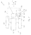
- the tillage machine 10 embodied as a soil compactor comprises a front carriage 12 and a rear carriage 14 pivotally connected thereto.
- a cultivating roller 16 is rotatably supported for machining, for example, compacting a bottom 18 about a roller rotational axis.
- driving wheels 20 and a driver's cab 22 are provided at the rear 14 .
- the drive wheels 20 are arranged on both sides of an internal combustion engine of a drive system 24 which will be described below.
- the Fig. 2 to 5 show the relative positioning of various system areas on the rear carriage 14 with respect to a machine longitudinal direction L and a cross machine direction Q.
- the Figure 5 For example, arranged in the cross-machine direction Q substantially in a central region of the internal combustion engine 26 of the drive system 24.
- the internal combustion engine 26 provides the energy required for the operation of the tillage machine 10. This can be stored either using a generator assembly in an energy storage, from which then electrically powered motors are fed for example for the drive, an imbalance drive or the like.
- a hydraulic system may be operated by the engine 26 to power hydraulic motors, such as for traction drive or for operating various units of the soil tillage implement 10.
- the drive wheels 20 are located on both sides of the internal combustion engine 26 arranged in a central region in the cross-machine direction Q.
- the driver's cab 22 which is offset in the machine longitudinal direction L with respect to the internal combustion engine 26, but at least partially overlap with this.
- the driver's cab 22 is located substantially in front of the internal combustion engine 26 or between the internal combustion engine 26 and the cultivating roller 16.
- a fuel tank 28 for the fuel for example diesel fuel, which is the internal combustion engine 26 to be supplied.
- the internal combustion engine 26 and the fuel tank 28 are thus consecutive in the machine longitudinal direction L.
- the fuel tank 28 is positioned substantially centrally and below the cab 22.
- a hydraulic fluid tank 32 is provided. This is located in the cross-machine direction Q substantially adjacent to the additive tank 30 and substantially overlaps therewith, so that the additive tank 30 in the machine longitudinal direction L is substantially between the drive wheel 20 and the hydraulic fluid tank 32.
- a fuel filler neck 34 of the fuel tank 28 is positioned to extend from the fuel tank 28 substantially centrally positioned in the cross-machine direction Q to the side 36 of the rear dolly 14 on which the additive tank 30 and the hydraulic fluid tank 32 are also positioned.
- the fuel filler neck 34 thus lies substantially between the additive tank 30 and the drive wheel 20 and, like the Fig. 2 this clarifies, in the machine longitudinal direction L overlap partially with the drive wheel 20.
- a fuel filler port 38 provided on this fuel filler neck 34 is positioned in the cross-machine direction Q substantially adjacent to and near an additive filler port 40 of the additive tank 30, respectively.
- the Kraftstoffein spallötechnisch 38 and the qualify fürin colllö réelle 40 thus lie on the same side 36 of the rear carriage 14 and are easily accessible for filling the respective liquid substances. Also a filling opening of the hydraulic fluid tank 32 may be arranged on this side 36 and in the machine longitudinal direction L following the other filling openings.
- Fig. 2 to 5 show further that not only the centrally positioned fuel tank 28 is substantially below the operator's cab 22, but that the operator's cab 22 in the machine longitudinal direction L and also the cross-machine direction Q substantially overlaps the additive tank 30 and also the hydraulic fluid tank 32.
- the space available there is efficiently utilized.
- a protection for the additive tank 30 and the hydraulic fluid tank 32 is achieved by the driver's cab 22 and the drive wheel 20 against action from above or from behind.
- a cover not shown in the figures can be further provided, which the additive tank 30, possibly also the hydraulic fluid tank 32, box-like covered and, for example, in the region of respective filling openings may have a recess or may be partially or completely removable.
Abstract
Eine Bodenbearbeitungsmaschine, insbesondere Bodenverdichter, umfasst - einen Hinterwagen (14) mit einer Brennkraftmaschine (26), - beidseits der Brennkraftmaschine (26) jeweils wenigstens ein Antriebsrad (20), - eine in einer Maschinenlängsrichtung (L) bezüglich der Brennkraftmaschine (26) versetzt angeordnete Fahrerkabine (22), - einen Kraftstofftank (28) für der Brennkraftmaschine (26) zuzuführenden Kraftstoff, - einen Zusatzstofftank (30), - einen Hydraulikflüssigkeitstank (32), wobei der Zusatzstofftank (30) in der Maschinenlängsrichtung (L) auf ein Antriebsrad (20) folgend und in einer Maschinenquerrichtung im Wesentlichen neben dem Antriebsrad (20) angeordnet ist.A soil tillage machine, in particular soil compactor, comprises a rear carriage (14) with an internal combustion engine (26), - On both sides of the internal combustion engine (26) each have at least one drive wheel (20), a driver's cab (22) arranged offset in a machine longitudinal direction (L) with respect to the internal combustion engine (26), a fuel tank (28) for the internal combustion engine (26) to be supplied fuel, an additive tank (30), a hydraulic fluid tank (32), wherein the additive tank (30) is arranged following a drive wheel (20) in the machine longitudinal direction (L) and substantially adjacent the drive wheel (20) in a cross-machine direction.
Description
Die vorliegende Erfindung betrifft eine Bodenbearbeitungsmaschine, insbesondere einen Bodenverdichter, der zur Durchführung von Bodenbearbeitungsvorgängen, wie z.B. zum Verdichten von Asphaltmaterial, Schottermaterial oder Erdreich eingesetzt werden kann.The present invention relates to a tillage machine, in particular a soil compactor, suitable for carrying out tillage operations, e.g. can be used for compacting asphalt material, gravel material or soil.
Ein derartiger Bodenverdichter ist im Allgemeinen mit einem Hinterwagen aufgebaut, an dem beidseits einer Brennkraftmaschine jeweils wenigstens ein Antriebsrad vorgesehen ist. An einem bezüglich des Hinterwagens schwenkbaren Vorderwagen ist eine Bodenbearbeitungswalze, beispielsweise Verdichterwalze, um eine Walzendrehachse drehbar, welche sich im Wesentlichen in einer Maschinenquerrichtung erstreckt.Such a soil compactor is generally constructed with a rear carriage, on each of which at least one drive wheel is provided on both sides of an internal combustion engine. On a front carriage pivotable with respect to the rear carriage, a cultivating roller, for example a compacting roller, is rotatable about a roller rotational axis which extends substantially in a cross-machine direction.
Um die immer strenger werdenden Anforderungen hinsichtlich des Schadstoffausstoßes erfüllen zu können, wird bei derartigen Maschinen den aus der Brennkraftmaschine derselben, im Allgemeinen einem Dieselaggregat, ausgestoßenen Abgasen ein Zusatzstoff beigemengt, beispielsweise Harnstoff. In einer im Abgasströmungsweg vorgesehenen Katalysatoranordnung können dann unter Umsetzung des Zusatzstoffes chemische Reaktionen ablaufen, welche zu einem verminderten Stickoxidausstoß führen.In order to meet the increasingly stringent requirements in terms of pollutant emissions, in such machines from the internal combustion engine thereof, generally a diesel engine, expelled exhaust gases added an additive, such as urea. In a catalyst arrangement provided in the exhaust gas flow path, chemical reactions can then take place when the additive reacts, which leads to a reduced emission of nitrogen oxide.
Aus der
Es ist die Aufgabe der vorliegenden Erfindung, eine Bodenbearbeitungsmaschine, insbesondere einen Bodenverdichter, vorzusehen, welche bei optimierter Bauraumausnutzung eine eine übermäßige Erwärmung vermeidende Positionierung eines Zusatzstofftanks ermöglicht.It is the object of the present invention to provide a soil cultivating machine, in particular a soil compactor, which, with an optimized use of space, makes it possible to position an additive tank avoiding excessive heating.
Erfindungsgemäß wird diese Aufgabe gelöst durch eine Bodenbearbeitungsmaschine, insbesondere Bodenverdichter, umfassend:
- einen Hinterwagen mit einer Brennkraftmaschine,
- beidseits der Brennkraftmaschine jeweils wenigstens eine Antriebsrad,
- eine in einer Maschinenlängsrichtung bezüglich der Brennkraftmaschine versetzt angeordnete Fahrerkabine,
- einen Kraftstofftank für der Brennkraftmaschine zuzuführenden Kraftstoff,
- einen Zusatzstofftank,
- einen Hydraulikflüssigkeitstank.
- a rear carriage with an internal combustion engine,
- on both sides of the internal combustion engine in each case at least one drive wheel,
- an offset in a machine longitudinal direction with respect to the internal combustion engine cab,
- a fuel tank for the internal combustion engine to be supplied fuel,
- an additive tank,
- a hydraulic fluid tank.
Bei einer derart aufgebauten Bodenbearbeitungsmaschine ist erfindungsgemäß weiter vorgesehen, dass der Zusatzstofftank in der Maschinenlängsrichtung auf ein Antriebsrad folgend und in einer Maschinenquerrichtung im Wesentlichen neben dem Antriebsrad angeordnet ist.In a soil cultivating machine constructed in this way, it is further provided according to the invention that the additive substance tank is arranged following a drive wheel in the machine longitudinal direction and substantially next to the drive wheel in a cross-machine direction.
Bei derartiger Positionierung des Zusatzstofftanks ist dieser vergleichsweise weit weg von der Brennkraftmaschine positioniert und zumindest bereichsweise durch das Antriebsrad bezüglich der Brennkraftmaschine gegen Wärmeübertrag geschützt. Ferner liegt der Zusatzstofftank bei derartiger Positionierung in einem Bereich, der im Wesentlichen seitlich am Hinterwagen ist und somit insbesondere zum Befüllen des Zusatzstofftanks leicht zugänglich ist.With such positioning of the additive tank this is positioned comparatively far away from the engine and at least partially protected by the drive wheel with respect to the internal combustion engine against heat transfer. Further, the additive tank is in such a positioning in an area which is substantially laterally on the rear carriage and thus in particular for filling the additive tank is easily accessible.
Dabei kann beispielsweise vorgesehen sein, dass der Zusatzstofftank in der Maschinenlängsrichtung unmittelbar auf das Antriebsrad folgend angeordnet ist. Somit wird eine kompakte Bauart erhalten, bei welcher jedoch nicht ausgeschlossen ist, dass ein das Antriebsrad abdeckendes Schutzblech oder dgl. zwischen dem Antriebsrad und dem Zusatzstofftank liegt. Es liegt in diesem Bereich jedoch erfindungsgemäß kein weiterer TankIt can be provided, for example, that the additive tank is arranged directly following the drive wheel in the machine longitudinal direction. Thus, a compact design is obtained in which, however, is not excluded that a drive wheel covering fender or the like. Between the drive wheel and the additive tank. However, according to the invention, there is no further tank in this area
Wenn der Zusatzstofftank in der Maschinenlängsrichtung zwischen dem Antriebsrad und dem Hydraulikflüssigkeitstank angeordnet ist, wird eine kompakte Bauart bei ebenfalls leichter Zugänglichkeit des Hydraulikflüssigkeitstanks zum Nachfüllen von Hydraulikflüssigkeit ermöglicht.If the additive tank is arranged in the machine longitudinal direction between the drive wheel and the hydraulic fluid tank, a compact design is also made possible with easy accessibility of the hydraulic fluid tank for replenishment of hydraulic fluid.
Bei einer alternativen Ausgestaltung kann vorgesehen sein, dass der Hydraulikflüssigkeitstank in der Maschinenlängsrichtung zwischen dem Antriebsrad und dem Zusatzstofftank angeordnet ist. Hier folgt also der Hydraulikflüssigkeitstank z.B. unmittelbar auf das Antriebsrad und schirmt somit den Zusatzstofftank noch besser gegen die Brennkraftmaschine ab.In an alternative embodiment it can be provided that the hydraulic fluid tank is arranged in the machine longitudinal direction between the drive wheel and the additive tank. Here, therefore, the hydraulic fluid tank follows, e.g. directly on the drive wheel and thus shields the additive tank even better against the internal combustion engine.
Der Zusatzstofftank und der Hydraulikflüssigkeitstank können dabei in der Maschinenquerrichtung im Wesentlichen nebeneinanderliegend angeordnet sein, was die leichte Zugänglichkeit dieser beiden Tanks an der gleichen Seite des Hinterwagens ermöglicht.The additive tank and the hydraulic fluid tank can be arranged substantially side by side in the cross-machine direction, which enables the easy accessibility of these two tanks on the same side of the rear carriage.
Eine effiziente Bauraumausnutzung kann bei einer Weiterbildung der Bodenbearbeitungsmaschine dadurch erreicht werden, dass der Zusatzstofftank oder/und der Hydraulikflüssigkeitstank wenigstens bereichsweise unter der Fahrerkabine angeordnet ist.Efficient space utilization can be achieved in a further development of the soil working machine in that the additive tank and / or the hydraulic fluid tank is arranged at least partially under the driver's cab.
Der Kraftstofftank kann in der Maschinenlängsrichtung auf die Brennkraftmaschine folgend und in der Maschinenquerrichtung in einem zentralen Bereich des Hinterwagens angeordnet sein. Dabei können der Zusatzstofftank und der Kraftstofftank sich in der Maschinenlängsrichtung wenigstens teilweise überlappend angeordnet sein.The fuel tank may be arranged in the machine longitudinal direction following the internal combustion engine and in the cross machine direction in a central region of the rear carriage. In this case, the additive tank and the fuel tank can be arranged in the machine longitudinal direction at least partially overlapping.
Insbesondere bei derartiger nahe beieinander liegender Positionierung des Zusatzstofftanks und des Kraftstofftanks kann weiter vorgesehen sein, dass ein Kraftstoffeinfüllstutzen des Kraftstofftanks sich wenigstens bereichsweise zwischen dem Zusatzstofftank und dem Antriebsrad erstreckt. Infolge dessen kann eine Positionierung erreicht werden, bei welcher eine Einfüllöffnung des Kraftstofftanks oder/und eine Einfüllöffnung des Zusatzstofftanks oder/und eine Einfüllöffnung des Hydraulikflüssigkeitstanks an der selben Seite des Hinterwagens oder/und in der Maschinenlängsrichtung im Wesentlichen aufeinander folgend angeordnet sind. Somit sind die Einfüllöffnungen des Kraftstofftanks und des Zusatzstofftanks an der gleichen Seite des Hinterwagens gut zugänglich.In particular, with such close positioning of the additive tank and the fuel tank can be further provided that a fuel filler neck of the fuel tank extends at least partially between the additive tank and the drive wheel. As a result, a positioning can be achieved, in which a filling opening of the fuel tank and / or a filling opening of the additive tank and / or a filling opening of the hydraulic fluid tank on the same side of the rear carriage and / or are arranged substantially successively in the machine longitudinal direction. Thus, the filling openings of the fuel tank and the additive tank on the same side of the rear carriage are easily accessible.
Insbesondere beim Aufbau der Bodenbearbeitungsmaschine als Bodenverdichter kann ein Vorderwagen mit dem Hinterwagen schwenkbar verbunden sein, wobei am Vorderwagen eine Bodenbearbeitungswalze um eine im Wesentlichen in der Maschinenquerrichtung sich erstreckende Walzendrehachse drehbar ist.In particular, when building the tillage machine as a soil compactor, a front end can be pivotally connected to the rear carriage, wherein at the front of a tillage roller is rotatable about a substantially in the cross machine direction extending roller rotation axis.
Die vorliegende Erfindung wird nachfolgend mit Bezug auf die beiliegenden Figuren detailliert beschrieben. Es zeigt:
- Fig. 1
- eine Seitenansicht einer als Bodenverdichter ausgeführten Bodenbearbeitungsmaschine;
- Fig. 2
- eine Seitenansicht eines Hinterwagens;
- Fig. 3
- eine Frontansicht des Hinterwagens;
- Fig. 4
- eine Draufsicht auf den Hinterwagen;
- Fig. 5
- eine Prinzipdarstellung, welche die Relativlage verschiedener Systembereiche am Hinterwagen zeigt.
- Fig. 1
- a side view of a soil compacting machine designed as a soil compactor;
- Fig. 2
- a side view of a rear carriage;
- Fig. 3
- a front view of the rear carriage;
- Fig. 4
- a plan view of the rear carriage;
- Fig. 5
- a schematic diagram showing the relative position of different system areas on the rear.
Die als Bodenverdichter ausgeführte Bodenbearbeitungsmaschine 10 umfasst einen Vorderwagen 12 und einen mit diesem schwenkbar verbundenen Hinterwagen 14. Am Vorderwagen 12 ist eine Bodenbearbeitungswalze 16 zum Bearbeiten, beispielsweise Verdichten eines Bodens 18 um eine Walzendrehachse drehbar getragen. Am Hinterwagen 14 sind Antriebsräder 20 und eine Fahrerkabine 22 vorgesehen. Die Antriebsräder 20 sind beidseits einer nachfolgend noch beschriebenen Brennkraftmaschine eines Antriebssystems 24 angeordnet.The tillage machine 10 embodied as a soil compactor comprises a
Die
In der Maschinenlängsrichtung L liegen beidseits der in einem zentralen Bereich in der Maschinenquerrichtung Q angeordneten Brennkraftmaschine 26 die Antriebsräder 20. In
Ebenfalls in einem zentralen Bereich in der Maschinenquerrichtung Q und in der Maschinenlängsrichtung L auf die Brennkraftmaschine 26 folgend liegt ein Kraftstofftank 28 für den Kraftstoff, also beispielsweise Dieselkraftstoff, welcher der Brennkraftmaschine 26 zuzuführen ist. Die Brennkraftmaschine 26 und der Kraftstofftank 28 liegen somit in der Maschinenlängsrichtung L aufeinander folgend. Der Kraftstofftank 28 ist im Wesentlichen zentral und unter der Fahrerkabine 22 positioniert.Also in a central region in the cross machine direction Q and in the machine longitudinal direction L following the
In der Maschinenlängsrichtung L auf das in
In der Maschinenlängsrichtung L auf den Zusatzstofftank folgend ist ein Hydraulikflüssigkeitstank 32 vorgesehen. Dieser liegt in der Maschinenquerrichtung Q im Wesentlichen neben dem Zusatzstofftank 30 und überlappt sich mit diesem im Wesentlichen, so dass der Zusatzstofftank 30 in der Maschinenlängsrichtung L im Wesentlichen zwischen dem Antriebsrad 20 und dem Hydraulikflüssigkeitstank 32 liegt.Following in the machine longitudinal direction L on the additive tank, a
Ein Kraftstoffeinfüllstutzen 34 des Kraftstofftanks 28 ist so positioniert, dass er sich ausgehend von dem in der Maschinenquerrichtung Q im Wesentlichen zentral positionierten Kraftstofftank 28 zu derjenigen Seite 36 des Hinterwagens 14 erstreckt, an welcher auch der Zusatzstofftank 30 und der Hydraulikflüssigkeitstank 32 positioniert sind. Der Kraftstoffeinfüllstutzen 34 liegt somit im Wesentlichen zwischen dem Zusatzstofftank 30 und dem Antriebsrad 20 und kann, wie die
Die
Durch die in den Figuren dargestellte Relativpositionierung der verschiedenen Tanks bezüglich des Antriebsaggregats 26, bezüglich der Fahrerkabine 22 und auch bezüglich eines der Antriebsräder 20 wird bei kompakter Ausgestaltung und effizienter Bauraumausnutzung einerseits eine leichte Zugänglichkeit der verschiedenen Tanks zum Befüllen, ggf. auch zum Überprüfen der Füllstände, gewährleistet. Gleichzeitig ist durch das Umgeben insbesondere des Zusatzstofftanks 30 und des Hydraulikflüssigkeitsktanks 32 mit anderen Systemkomponenten des Hinterwagens eines Schutzwirkung vorgesehen. Der Zusatzstofftank 30 liegt, teilweise auch abgeschirmt durch den Kraftstofftank 28 und das Antriebsrad 20, zwar vergleichsweise nahe an der Brennkraftmaschine 26, ist bezüglich dieser jedoch thermisch gut abgeschirmt. Dies ermöglicht auch einen vergleichsweise kurzen Strömungsweg für den Zusatzstoff zwischen dem Zusatzstofftank 30 und einem von der Brennkraftmaschine 26 beispielsweise in einem Bereich hinter der Fahrerkabine 22 nach außen führenden Abgasleitungssystem.Due to the relative positioning of the various tanks with respect to the
Da die Einfüllöffnungen für den Kraftstofftank 28 und auch den Zusatzstofftank 30 in einem Bereich liegen, welche im Allgemeinen durch eine Abdeckhaube 42 für die Brennkraftmaschine 26 nicht überdeckt ist, ist es zum Befüllen dieser Tanks auch nicht erforderlich, diese Abdeckhaube 42 zu bewegen.Since the filling openings for the
Claims (11)
dadurch gekennzeichnet, dass der Zusatzstofftank (30) in der Maschinenlängsrichtung (L) unmittelbar auf das Antriebsrad (20) folgend angeordnet ist.Soil cultivation machine according to claim 1,
characterized in that the additive tank (30) in the machine longitudinal direction (L) is arranged directly following the drive wheel (20).
dadurch gekennzeichnet, dass der Zusatzstofftank (30) in der Maschinenlängsrichtung (L) zwischen dem Antriebsrad (20) und dem Hydraulikflüssigkeitstank (32) angeordnet ist.Soil cultivation machine according to claim 1 or 2,
characterized in that the additive tank (30) is arranged in the machine longitudinal direction (L) between the drive wheel (20) and the hydraulic fluid tank (32).
dadurch gekennzeichnet, dass der Hydraulikflüssigkeitstank (32) in der Maschinenlängsrichtung (L) zwischen dem Antriebsrad (20) und dem Zusatzstofftank (30) angeordnet ist.Soil cultivation machine according to claim 1,
characterized in that the hydraulic fluid tank (32) is arranged in the machine longitudinal direction (L) between the drive wheel (20) and the additive tank (30).
dadurch gekennzeichnet, dass der Zusatzstofftank (30) und der Hydraulikflüssigkeitstank in der Maschinenquerrichtung (Q) im Wesentlichen nebeneinander liegend angeordnet sind.Soil cultivation machine according to one of claims 1 to 4,
characterized in that the additive tank (30) and the hydraulic fluid tank are arranged substantially side by side in the cross-machine direction (Q).
dadurch gekennzeichnet, dass der Zusatzstofftank (30) oder/und der Hydraulikflüssigkeitstank (32) wenigstens bereichsweise unter der Fahrerkabine (22) angeordnet ist.Soil cultivation machine according to one of claims 1 to 5,
characterized in that the additive tank (30) and / or the hydraulic fluid tank (32) at least partially under the driver's cab (22) is arranged.
dadurch gekennzeichnet, dass der Kraftstofftank (28) in der Maschinenlängsrichtung (L) auf die Brennkraftmaschine (26) folgend und in der Maschinenquerrichtung (Q) in einem zentralen Bereich des Hinterwagens (14) angeordnet ist.Soil cultivation machine according to one of claims 1 to 6,
characterized in that the fuel tank (28) is arranged in the machine longitudinal direction (L) following the internal combustion engine (26) and in the cross machine direction (Q) in a central region of the rear carriage (14).
dadurch gekennzeichnet, dass der Zusatzstofftank (30) und der Kraftstofftank (28) sich in der Maschinenlängsrichtung (L) wenigstens teilweise überlappend angeordnet sind.Soil cultivation machine according to one of claims 1 to 7,
characterized in that the additive tank (30) and the fuel tank (28) are arranged in the machine longitudinal direction (L) at least partially overlapping.
dadurch gekennzeichnet, dass ein Kraftstoffeinfüllstutzen (34) des Kraftstofftanks (28) sich wenigstens bereichsweise zwischen dem Zusatzstofftank (30) und dem Antriebsrad (20) erstreckt.Soil cultivation machine according to one of claims 1 to 8,
characterized in that a fuel filler neck (34) of the fuel tank (28) extends at least partially between the additive tank (30) and the drive wheel (20).
dadurch gekennzeichnet, dass eine Einfüllöffnung (38) des Kraftstofftanks (28) oder/und eine Einfüllöffnung (40) des Zusatzstofftanks (30) oder/und eine Einfüllöffnung des Hydraulikflüssigkeitstanks (32) an der selben Seite (36) des Hinterwagens (14) oder/und in der Maschinenlängsrichtung (L) im Wesentlichen aufeinander folgend angeordnet sind.Soil cultivation machine according to one of claims 1 to 9,
characterized in that a filling opening (38) of the fuel tank (28) and / or a filling opening (40) of the additive tank (30) and / or a filling opening of the hydraulic fluid tank (32) on the same side (36) of the rear carriage (14) or / and in the machine longitudinal direction (L) are arranged substantially successively.
dadurch gekennzeichnet, dass ein Vorderwagen (12) mit dem Hinterwagen (14) schwenkbar verbunden ist, wobei am Vorderwagen (12) eine Bodenbearbeitungswalze (16) um eine im Wesentlichen in Maschinenquerrichtung (Q) sich erstreckende Walzendrehachse drehbar ist.Soil cultivation machine according to one of claims 1 to 10,
characterized in that a front carriage (12) is pivotally connected to the rear carriage (14), wherein on the front carriage (12) a tilling roller (16) is rotatable about a substantially in the cross machine direction (Q) extending roller rotation axis.
Applications Claiming Priority (1)
| Application Number | Priority Date | Filing Date | Title |
|---|---|---|---|
| DE102014118995.7A DE102014118995A1 (en) | 2014-12-18 | 2014-12-18 | Soil preparation machine, in particular soil compactor |
Publications (3)
| Publication Number | Publication Date |
|---|---|
| EP3034347A1 true EP3034347A1 (en) | 2016-06-22 |
| EP3034347B1 EP3034347B1 (en) | 2017-05-10 |
| EP3034347B2 EP3034347B2 (en) | 2023-01-18 |
Family
ID=54936784
Family Applications (1)
| Application Number | Title | Priority Date | Filing Date |
|---|---|---|---|
| EP15199708.7A Active EP3034347B2 (en) | 2014-12-18 | 2015-12-14 | Soil processing machine, in particular soil compactor |
Country Status (3)
| Country | Link |
|---|---|
| US (1) | US10214087B2 (en) |
| EP (1) | EP3034347B2 (en) |
| DE (2) | DE102014118995A1 (en) |
Cited By (1)
| Publication number | Priority date | Publication date | Assignee | Title |
|---|---|---|---|---|
| CN112663423A (en) * | 2020-12-17 | 2021-04-16 | 王泽远 | High-flatness construction method for asphalt pavement |
Families Citing this family (7)
| Publication number | Priority date | Publication date | Assignee | Title |
|---|---|---|---|---|
| JP6615668B2 (en) * | 2016-03-30 | 2019-12-04 | 住友建機株式会社 | Asphalt finisher |
| US10801179B2 (en) | 2017-12-15 | 2020-10-13 | Cnh Industrial America Llc | Hydraulic fluid storage tank including quick connect coupling |
| JP6708685B2 (en) | 2018-03-23 | 2020-06-10 | 日立建機株式会社 | Work vehicle tank |
| JP6752248B2 (en) * | 2018-03-23 | 2020-09-09 | 日立建機株式会社 | Work vehicle |
| US11293155B2 (en) | 2018-10-10 | 2022-04-05 | Maximum Density LLC | Landfill compactor |
| DE102019133272A1 (en) | 2019-12-06 | 2021-06-10 | Hamm Ag | Tank system |
| US11891774B2 (en) * | 2021-03-26 | 2024-02-06 | Caterpillar Inc. | Structurally integrated fuel tank |
Citations (3)
| Publication number | Priority date | Publication date | Assignee | Title |
|---|---|---|---|---|
| EP2431536A1 (en) * | 2010-09-16 | 2012-03-21 | Hitachi Construction Machinery Co., Ltd. | Construction machine |
| EP2754870A1 (en) | 2013-01-11 | 2014-07-16 | Joseph Vögele AG | Construction machine with heat management system |
| US20140290224A1 (en) * | 2013-03-26 | 2014-10-02 | Komatsu Ltd. | Wheel loader |
Family Cites Families (21)
| Publication number | Priority date | Publication date | Assignee | Title |
|---|---|---|---|---|
| CA2042890A1 (en) | 1991-05-17 | 1992-11-18 | Charles L. Poley | Soil compactor |
| DE29805539U1 (en) * | 1998-03-26 | 1998-06-18 | Vibromax Bodenverdichtungsmasc | Soil compaction machine |
| JP2000192415A (en) | 1998-12-24 | 2000-07-11 | Hitachi Constr Mach Co Ltd | Road roller |
| JP2002242121A (en) | 2001-02-13 | 2002-08-28 | Sakai Heavy Ind Ltd | Rolling compaction vehicle |
| DE102005029415A1 (en) † | 2005-06-24 | 2006-12-28 | Man Nutzfahrzeuge Ag | Motor vehicle with a reducing agent space for an emission control system |
| US7967099B2 (en) * | 2008-06-19 | 2011-06-28 | Caterpillar Paving Products Inc. | Method and arrangement of a plurality of propel pumps in a hydrostatically driven compactor |
| EP2474672A4 (en) * | 2009-09-02 | 2017-01-18 | Hitachi Construction Machinery Co., Ltd. | Wheel type working vehicle |
| JP5402451B2 (en) * | 2009-09-17 | 2014-01-29 | コベルコ建機株式会社 | Construction machinery |
| JP5461453B2 (en) | 2011-01-31 | 2014-04-02 | 日立建機株式会社 | Stepped pavement attachment |
| DE102011005275A1 (en) * | 2011-03-09 | 2012-09-13 | Hamm Ag | Self-propelled construction equipment, in particular soil compactors |
| USD668269S1 (en) | 2011-04-28 | 2012-10-02 | Sakai Heavy Industries, Ltd. | Vibratory roller |
| DE102011085240A1 (en) | 2011-10-26 | 2013-05-02 | Hamm Ag | Self-propelled soil compactor |
| US8695827B2 (en) | 2012-05-01 | 2014-04-15 | Deere & Company | Diesel exhaust fluid and fuel fill system |
| CA2779475C (en) * | 2012-05-29 | 2015-04-07 | Macdon Industries Ltd. | Windrower tractor with parallel heat exchangers for cooling of engine and associated fluids |
| JP5997507B2 (en) | 2012-06-01 | 2016-09-28 | 日立建機株式会社 | Rolling machine |
| JP2013249665A (en) | 2012-06-01 | 2013-12-12 | Hitachi Constr Mach Co Ltd | Rolling compaction machine |
| JP5911392B2 (en) * | 2012-07-20 | 2016-04-27 | 株式会社クボタ | Work vehicle |
| DE102012112666B3 (en) † | 2012-12-19 | 2014-03-27 | Elkamet Kunststofftechnik Gmbh | Covering structure for resource container system for vehicle e.g. truck, has filler neck portion that is designed as terminal portion for resource spacer and is provided in apertures extending along cover housing wall |
| KR102138732B1 (en) * | 2013-04-26 | 2020-07-28 | 얀마 파워 테크놀로지 가부시키가이샤 | Work vehicle |
| US20150022334A1 (en) * | 2013-07-19 | 2015-01-22 | Deere & Company | Progressive alert system for vehicle reservoir fluid fill level |
| JP2016098731A (en) * | 2014-11-21 | 2016-05-30 | キャタピラー エス エー アール エル | Machine body and work machine |
-
2014
- 2014-12-18 DE DE102014118995.7A patent/DE102014118995A1/en active Pending
- 2014-12-18 DE DE202014010518.9U patent/DE202014010518U1/en not_active Withdrawn - After Issue
-
2015
- 2015-12-14 EP EP15199708.7A patent/EP3034347B2/en active Active
- 2015-12-16 US US14/971,078 patent/US10214087B2/en active Active
Patent Citations (3)
| Publication number | Priority date | Publication date | Assignee | Title |
|---|---|---|---|---|
| EP2431536A1 (en) * | 2010-09-16 | 2012-03-21 | Hitachi Construction Machinery Co., Ltd. | Construction machine |
| EP2754870A1 (en) | 2013-01-11 | 2014-07-16 | Joseph Vögele AG | Construction machine with heat management system |
| US20140290224A1 (en) * | 2013-03-26 | 2014-10-02 | Komatsu Ltd. | Wheel loader |
Cited By (2)
| Publication number | Priority date | Publication date | Assignee | Title |
|---|---|---|---|---|
| CN112663423A (en) * | 2020-12-17 | 2021-04-16 | 王泽远 | High-flatness construction method for asphalt pavement |
| CN112663423B (en) * | 2020-12-17 | 2022-06-14 | 湖北交投建设集团有限公司 | High-flatness construction method for asphalt pavement |
Also Published As
| Publication number | Publication date |
|---|---|
| EP3034347B1 (en) | 2017-05-10 |
| DE202014010518U1 (en) | 2015-11-09 |
| US10214087B2 (en) | 2019-02-26 |
| EP3034347B2 (en) | 2023-01-18 |
| US20160176278A1 (en) | 2016-06-23 |
| DE102014118995A1 (en) | 2016-06-23 |
Similar Documents
| Publication | Publication Date | Title |
|---|---|---|
| EP3034347B1 (en) | Soil processing machine, in particular soil compactor | |
| EP2146820B1 (en) | Machine tool, particularly hand machine tool | |
| DE69928608T2 (en) | Tiller with edge milling option | |
| EP1053902B1 (en) | Vehicle with heat source, heat exchanger und cover | |
| DE112012000007B4 (en) | Construction machinery | |
| EP2876209B1 (en) | Self-propelled construction vehicle | |
| DE112012003697B4 (en) | Exhaust gas treatment unit | |
| DE112013000147T5 (en) | working vehicle | |
| DE2241244A1 (en) | COMPRESSED AIR MOTOR AND COMPRESSED AIR SANDING MACHINE EQUIPPED WITH IT | |
| DE112015000106T5 (en) | hydraulic excavators | |
| DE112013003495T5 (en) | Cold milling machine with multiple inlet extraction system | |
| EP0014695B1 (en) | Cutter head with water nozzles and process for operating this head | |
| DE112012000378B4 (en) | hydraulic excavators | |
| DE102017126634A1 (en) | CIRCULAR MIXER AND SYSTEM AND METHOD THEREFOR | |
| DE112012000301B4 (en) | hydraulic excavators | |
| DE112012000064T5 (en) | Construction machinery | |
| DE202007003326U1 (en) | Road finisher, comprises emission removal duct guided through housing of muffler | |
| EP1522688B1 (en) | Self-propelled road milling machine with a cooling system | |
| DE112015000025B4 (en) | Hydraulic excavator | |
| DE112015000192T5 (en) | hydraulic excavators | |
| DE102011088568B4 (en) | Vehicle heater | |
| DE4213406C2 (en) | Construction machine | |
| DE19839783B4 (en) | Control valve mechanism for a work vehicle with a rotatable structure | |
| DE112015000090B4 (en) | Wheel loader | |
| DE3511645C2 (en) | Road working machine |
Legal Events
| Date | Code | Title | Description |
|---|---|---|---|
| PUAI | Public reference made under article 153(3) epc to a published international application that has entered the european phase |
Free format text: ORIGINAL CODE: 0009012 |
|
| 17P | Request for examination filed |
Effective date: 20151214 |
|
| AK | Designated contracting states |
Kind code of ref document: A1 Designated state(s): AL AT BE BG CH CY CZ DE DK EE ES FI FR GB GR HR HU IE IS IT LI LT LU LV MC MK MT NL NO PL PT RO RS SE SI SK SM TR |
|
| AX | Request for extension of the european patent |
Extension state: BA ME |
|
| GRAP | Despatch of communication of intention to grant a patent |
Free format text: ORIGINAL CODE: EPIDOSNIGR1 |
|
| RIC1 | Information provided on ipc code assigned before grant |
Ipc: E01C 19/28 20060101ALI20160929BHEP Ipc: B60K 15/063 20060101AFI20160929BHEP Ipc: E02F 9/08 20060101ALI20160929BHEP Ipc: E02D 3/026 20060101ALI20160929BHEP |
|
| INTG | Intention to grant announced |
Effective date: 20161027 |
|
| GRAJ | Information related to disapproval of communication of intention to grant by the applicant or resumption of examination proceedings by the epo deleted |
Free format text: ORIGINAL CODE: EPIDOSDIGR1 |
|
| STAA | Information on the status of an ep patent application or granted ep patent |
Free format text: STATUS: REQUEST FOR EXAMINATION WAS MADE |
|
| INTC | Intention to grant announced (deleted) | ||
| GRAS | Grant fee paid |
Free format text: ORIGINAL CODE: EPIDOSNIGR3 |
|
| STAA | Information on the status of an ep patent application or granted ep patent |
Free format text: STATUS: GRANT OF PATENT IS INTENDED |
|
| GRAP | Despatch of communication of intention to grant a patent |
Free format text: ORIGINAL CODE: EPIDOSNIGR1 |
|
| GRAA | (expected) grant |
Free format text: ORIGINAL CODE: 0009210 |
|
| STAA | Information on the status of an ep patent application or granted ep patent |
Free format text: STATUS: THE PATENT HAS BEEN GRANTED |
|
| INTG | Intention to grant announced |
Effective date: 20170316 |
|
| AK | Designated contracting states |
Kind code of ref document: B1 Designated state(s): AL AT BE BG CH CY CZ DE DK EE ES FI FR GB GR HR HU IE IS IT LI LT LU LV MC MK MT NL NO PL PT RO RS SE SI SK SM TR |
|
| REG | Reference to a national code |
Ref country code: GB Ref legal event code: FG4D Free format text: NOT ENGLISH |
|
| REG | Reference to a national code |
Ref country code: AT Ref legal event code: REF Ref document number: 891919 Country of ref document: AT Kind code of ref document: T Effective date: 20170515 Ref country code: CH Ref legal event code: EP |
|
| REG | Reference to a national code |
Ref country code: IE Ref legal event code: FG4D Free format text: LANGUAGE OF EP DOCUMENT: GERMAN |
|
| REG | Reference to a national code |
Ref country code: DE Ref legal event code: R096 Ref document number: 502015001036 Country of ref document: DE |
|
| REG | Reference to a national code |
Ref country code: SE Ref legal event code: TRGR |
|
| REG | Reference to a national code |
Ref country code: NL Ref legal event code: MP Effective date: 20170510 |
|
| REG | Reference to a national code |
Ref country code: LT Ref legal event code: MG4D |
|
| PG25 | Lapsed in a contracting state [announced via postgrant information from national office to epo] |
Ref country code: HR Free format text: LAPSE BECAUSE OF FAILURE TO SUBMIT A TRANSLATION OF THE DESCRIPTION OR TO PAY THE FEE WITHIN THE PRESCRIBED TIME-LIMIT Effective date: 20170510 Ref country code: GR Free format text: LAPSE BECAUSE OF FAILURE TO SUBMIT A TRANSLATION OF THE DESCRIPTION OR TO PAY THE FEE WITHIN THE PRESCRIBED TIME-LIMIT Effective date: 20170811 Ref country code: NO Free format text: LAPSE BECAUSE OF FAILURE TO SUBMIT A TRANSLATION OF THE DESCRIPTION OR TO PAY THE FEE WITHIN THE PRESCRIBED TIME-LIMIT Effective date: 20170810 Ref country code: LT Free format text: LAPSE BECAUSE OF FAILURE TO SUBMIT A TRANSLATION OF THE DESCRIPTION OR TO PAY THE FEE WITHIN THE PRESCRIBED TIME-LIMIT Effective date: 20170510 Ref country code: ES Free format text: LAPSE BECAUSE OF FAILURE TO SUBMIT A TRANSLATION OF THE DESCRIPTION OR TO PAY THE FEE WITHIN THE PRESCRIBED TIME-LIMIT Effective date: 20170510 Ref country code: FI Free format text: LAPSE BECAUSE OF FAILURE TO SUBMIT A TRANSLATION OF THE DESCRIPTION OR TO PAY THE FEE WITHIN THE PRESCRIBED TIME-LIMIT Effective date: 20170510 |
|
| PG25 | Lapsed in a contracting state [announced via postgrant information from national office to epo] |
Ref country code: IS Free format text: LAPSE BECAUSE OF FAILURE TO SUBMIT A TRANSLATION OF THE DESCRIPTION OR TO PAY THE FEE WITHIN THE PRESCRIBED TIME-LIMIT Effective date: 20170910 Ref country code: PL Free format text: LAPSE BECAUSE OF FAILURE TO SUBMIT A TRANSLATION OF THE DESCRIPTION OR TO PAY THE FEE WITHIN THE PRESCRIBED TIME-LIMIT Effective date: 20170510 Ref country code: BG Free format text: LAPSE BECAUSE OF FAILURE TO SUBMIT A TRANSLATION OF THE DESCRIPTION OR TO PAY THE FEE WITHIN THE PRESCRIBED TIME-LIMIT Effective date: 20170810 Ref country code: RS Free format text: LAPSE BECAUSE OF FAILURE TO SUBMIT A TRANSLATION OF THE DESCRIPTION OR TO PAY THE FEE WITHIN THE PRESCRIBED TIME-LIMIT Effective date: 20170510 Ref country code: NL Free format text: LAPSE BECAUSE OF FAILURE TO SUBMIT A TRANSLATION OF THE DESCRIPTION OR TO PAY THE FEE WITHIN THE PRESCRIBED TIME-LIMIT Effective date: 20170510 Ref country code: LV Free format text: LAPSE BECAUSE OF FAILURE TO SUBMIT A TRANSLATION OF THE DESCRIPTION OR TO PAY THE FEE WITHIN THE PRESCRIBED TIME-LIMIT Effective date: 20170510 |
|
| PG25 | Lapsed in a contracting state [announced via postgrant information from national office to epo] |
Ref country code: EE Free format text: LAPSE BECAUSE OF FAILURE TO SUBMIT A TRANSLATION OF THE DESCRIPTION OR TO PAY THE FEE WITHIN THE PRESCRIBED TIME-LIMIT Effective date: 20170510 Ref country code: DK Free format text: LAPSE BECAUSE OF FAILURE TO SUBMIT A TRANSLATION OF THE DESCRIPTION OR TO PAY THE FEE WITHIN THE PRESCRIBED TIME-LIMIT Effective date: 20170510 Ref country code: SK Free format text: LAPSE BECAUSE OF FAILURE TO SUBMIT A TRANSLATION OF THE DESCRIPTION OR TO PAY THE FEE WITHIN THE PRESCRIBED TIME-LIMIT Effective date: 20170510 Ref country code: RO Free format text: LAPSE BECAUSE OF FAILURE TO SUBMIT A TRANSLATION OF THE DESCRIPTION OR TO PAY THE FEE WITHIN THE PRESCRIBED TIME-LIMIT Effective date: 20170510 |
|
| REG | Reference to a national code |
Ref country code: DE Ref legal event code: R026 Ref document number: 502015001036 Country of ref document: DE |
|
| PLBI | Opposition filed |
Free format text: ORIGINAL CODE: 0009260 |
|
| PLAX | Notice of opposition and request to file observation + time limit sent |
Free format text: ORIGINAL CODE: EPIDOSNOBS2 |
|
| PG25 | Lapsed in a contracting state [announced via postgrant information from national office to epo] |
Ref country code: SM Free format text: LAPSE BECAUSE OF FAILURE TO SUBMIT A TRANSLATION OF THE DESCRIPTION OR TO PAY THE FEE WITHIN THE PRESCRIBED TIME-LIMIT Effective date: 20170510 Ref country code: IT Free format text: LAPSE BECAUSE OF FAILURE TO SUBMIT A TRANSLATION OF THE DESCRIPTION OR TO PAY THE FEE WITHIN THE PRESCRIBED TIME-LIMIT Effective date: 20170510 |
|
| 26 | Opposition filed |
Opponent name: BOMAG GMBH Effective date: 20180208 |
|
| PG25 | Lapsed in a contracting state [announced via postgrant information from national office to epo] |
Ref country code: SI Free format text: LAPSE BECAUSE OF FAILURE TO SUBMIT A TRANSLATION OF THE DESCRIPTION OR TO PAY THE FEE WITHIN THE PRESCRIBED TIME-LIMIT Effective date: 20170510 |
|
| PLBB | Reply of patent proprietor to notice(s) of opposition received |
Free format text: ORIGINAL CODE: EPIDOSNOBS3 |
|
| REG | Reference to a national code |
Ref country code: DE Ref legal event code: R082 Ref document number: 502015001036 Country of ref document: DE Representative=s name: RUTTENSPERGER LACHNIT TROSSIN GOMOLL PATENT- U, DE Ref country code: DE Ref legal event code: R082 Ref document number: 502015001036 Country of ref document: DE Representative=s name: RUTTENSPERGER LACHNIT TROSSIN GOMOLL, PATENT- , DE |
|
| REG | Reference to a national code |
Ref country code: IE Ref legal event code: MM4A |
|
| PG25 | Lapsed in a contracting state [announced via postgrant information from national office to epo] |
Ref country code: MT Free format text: LAPSE BECAUSE OF FAILURE TO SUBMIT A TRANSLATION OF THE DESCRIPTION OR TO PAY THE FEE WITHIN THE PRESCRIBED TIME-LIMIT Effective date: 20170510 Ref country code: LU Free format text: LAPSE BECAUSE OF NON-PAYMENT OF DUE FEES Effective date: 20171214 |
|
| REG | Reference to a national code |
Ref country code: FR Ref legal event code: ST Effective date: 20180831 |
|
| REG | Reference to a national code |
Ref country code: BE Ref legal event code: MM Effective date: 20171231 |
|
| PG25 | Lapsed in a contracting state [announced via postgrant information from national office to epo] |
Ref country code: FR Free format text: LAPSE BECAUSE OF NON-PAYMENT OF DUE FEES Effective date: 20180102 Ref country code: IE Free format text: LAPSE BECAUSE OF NON-PAYMENT OF DUE FEES Effective date: 20171214 |
|
| PG25 | Lapsed in a contracting state [announced via postgrant information from national office to epo] |
Ref country code: BE Free format text: LAPSE BECAUSE OF NON-PAYMENT OF DUE FEES Effective date: 20171231 |
|
| PG25 | Lapsed in a contracting state [announced via postgrant information from national office to epo] |
Ref country code: MC Free format text: LAPSE BECAUSE OF FAILURE TO SUBMIT A TRANSLATION OF THE DESCRIPTION OR TO PAY THE FEE WITHIN THE PRESCRIBED TIME-LIMIT Effective date: 20170510 Ref country code: HU Free format text: LAPSE BECAUSE OF FAILURE TO SUBMIT A TRANSLATION OF THE DESCRIPTION OR TO PAY THE FEE WITHIN THE PRESCRIBED TIME-LIMIT; INVALID AB INITIO Effective date: 20151214 |
|
| REG | Reference to a national code |
Ref country code: CH Ref legal event code: PL |
|
| PG25 | Lapsed in a contracting state [announced via postgrant information from national office to epo] |
Ref country code: CY Free format text: LAPSE BECAUSE OF FAILURE TO SUBMIT A TRANSLATION OF THE DESCRIPTION OR TO PAY THE FEE WITHIN THE PRESCRIBED TIME-LIMIT Effective date: 20170510 |
|
| PG25 | Lapsed in a contracting state [announced via postgrant information from national office to epo] |
Ref country code: MK Free format text: LAPSE BECAUSE OF FAILURE TO SUBMIT A TRANSLATION OF THE DESCRIPTION OR TO PAY THE FEE WITHIN THE PRESCRIBED TIME-LIMIT Effective date: 20170510 |
|
| PG25 | Lapsed in a contracting state [announced via postgrant information from national office to epo] |
Ref country code: CH Free format text: LAPSE BECAUSE OF NON-PAYMENT OF DUE FEES Effective date: 20181231 Ref country code: LI Free format text: LAPSE BECAUSE OF NON-PAYMENT OF DUE FEES Effective date: 20181231 |
|
| APBM | Appeal reference recorded |
Free format text: ORIGINAL CODE: EPIDOSNREFNO |
|
| APBP | Date of receipt of notice of appeal recorded |
Free format text: ORIGINAL CODE: EPIDOSNNOA2O |
|
| APAH | Appeal reference modified |
Free format text: ORIGINAL CODE: EPIDOSCREFNO |
|
| APBM | Appeal reference recorded |
Free format text: ORIGINAL CODE: EPIDOSNREFNO |
|
| APBP | Date of receipt of notice of appeal recorded |
Free format text: ORIGINAL CODE: EPIDOSNNOA2O |
|
| PG25 | Lapsed in a contracting state [announced via postgrant information from national office to epo] |
Ref country code: TR Free format text: LAPSE BECAUSE OF FAILURE TO SUBMIT A TRANSLATION OF THE DESCRIPTION OR TO PAY THE FEE WITHIN THE PRESCRIBED TIME-LIMIT Effective date: 20170510 |
|
| APBQ | Date of receipt of statement of grounds of appeal recorded |
Free format text: ORIGINAL CODE: EPIDOSNNOA3O |
|
| APBQ | Date of receipt of statement of grounds of appeal recorded |
Free format text: ORIGINAL CODE: EPIDOSNNOA3O |
|
| PG25 | Lapsed in a contracting state [announced via postgrant information from national office to epo] |
Ref country code: PT Free format text: LAPSE BECAUSE OF FAILURE TO SUBMIT A TRANSLATION OF THE DESCRIPTION OR TO PAY THE FEE WITHIN THE PRESCRIBED TIME-LIMIT Effective date: 20170510 |
|
| PG25 | Lapsed in a contracting state [announced via postgrant information from national office to epo] |
Ref country code: AL Free format text: LAPSE BECAUSE OF FAILURE TO SUBMIT A TRANSLATION OF THE DESCRIPTION OR TO PAY THE FEE WITHIN THE PRESCRIBED TIME-LIMIT Effective date: 20170510 |
|
| GBPC | Gb: european patent ceased through non-payment of renewal fee |
Effective date: 20191214 |
|
| PG25 | Lapsed in a contracting state [announced via postgrant information from national office to epo] |
Ref country code: GB Free format text: LAPSE BECAUSE OF NON-PAYMENT OF DUE FEES Effective date: 20191214 |
|
| REG | Reference to a national code |
Ref country code: AT Ref legal event code: MM01 Ref document number: 891919 Country of ref document: AT Kind code of ref document: T Effective date: 20201214 |
|
| PG25 | Lapsed in a contracting state [announced via postgrant information from national office to epo] |
Ref country code: AT Free format text: LAPSE BECAUSE OF NON-PAYMENT OF DUE FEES Effective date: 20201214 |
|
| APAN | Information on closure of appeal procedure modified |
Free format text: ORIGINAL CODE: EPIDOSCNOA9O |
|
| APBU | Appeal procedure closed |
Free format text: ORIGINAL CODE: EPIDOSNNOA9O |
|
| PUAH | Patent maintained in amended form |
Free format text: ORIGINAL CODE: 0009272 |
|
| STAA | Information on the status of an ep patent application or granted ep patent |
Free format text: STATUS: PATENT MAINTAINED AS AMENDED |
|
| 27A | Patent maintained in amended form |
Effective date: 20230118 |
|
| AK | Designated contracting states |
Kind code of ref document: B2 Designated state(s): AL AT BE BG CH CY CZ DE DK EE ES FI FR GB GR HR HU IE IS IT LI LT LU LV MC MK MT NL NO PL PT RO RS SE SI SK SM TR |
|
| REG | Reference to a national code |
Ref country code: DE Ref legal event code: R102 Ref document number: 502015001036 Country of ref document: DE |
|
| REG | Reference to a national code |
Ref country code: SE Ref legal event code: RPEO |
|
| PGFP | Annual fee paid to national office [announced via postgrant information from national office to epo] |
Ref country code: SE Payment date: 20231220 Year of fee payment: 9 Ref country code: DE Payment date: 20231214 Year of fee payment: 9 Ref country code: CZ Payment date: 20231206 Year of fee payment: 9 |