EP2146820B1 - Machine tool, particularly hand machine tool - Google Patents
Machine tool, particularly hand machine tool Download PDFInfo
- Publication number
- EP2146820B1 EP2146820B1 EP08708891A EP08708891A EP2146820B1 EP 2146820 B1 EP2146820 B1 EP 2146820B1 EP 08708891 A EP08708891 A EP 08708891A EP 08708891 A EP08708891 A EP 08708891A EP 2146820 B1 EP2146820 B1 EP 2146820B1
- Authority
- EP
- European Patent Office
- Prior art keywords
- housing
- air guide
- power tool
- functional
- functional section
- Prior art date
- Legal status (The legal status is an assumption and is not a legal conclusion. Google has not performed a legal analysis and makes no representation as to the accuracy of the status listed.)
- Active
Links
Images


Classifications
-
- B—PERFORMING OPERATIONS; TRANSPORTING
- B24—GRINDING; POLISHING
- B24B—MACHINES, DEVICES, OR PROCESSES FOR GRINDING OR POLISHING; DRESSING OR CONDITIONING OF ABRADING SURFACES; FEEDING OF GRINDING, POLISHING, OR LAPPING AGENTS
- B24B23/00—Portable grinding machines, e.g. hand-guided; Accessories therefor
- B24B23/02—Portable grinding machines, e.g. hand-guided; Accessories therefor with rotating grinding tools; Accessories therefor
- B24B23/028—Angle tools
-
- B—PERFORMING OPERATIONS; TRANSPORTING
- B25—HAND TOOLS; PORTABLE POWER-DRIVEN TOOLS; MANIPULATORS
- B25F—COMBINATION OR MULTI-PURPOSE TOOLS NOT OTHERWISE PROVIDED FOR; DETAILS OR COMPONENTS OF PORTABLE POWER-DRIVEN TOOLS NOT PARTICULARLY RELATED TO THE OPERATIONS PERFORMED AND NOT OTHERWISE PROVIDED FOR
- B25F5/00—Details or components of portable power-driven tools not particularly related to the operations performed and not otherwise provided for
- B25F5/008—Cooling means
-
- B—PERFORMING OPERATIONS; TRANSPORTING
- B25—HAND TOOLS; PORTABLE POWER-DRIVEN TOOLS; MANIPULATORS
- B25F—COMBINATION OR MULTI-PURPOSE TOOLS NOT OTHERWISE PROVIDED FOR; DETAILS OR COMPONENTS OF PORTABLE POWER-DRIVEN TOOLS NOT PARTICULARLY RELATED TO THE OPERATIONS PERFORMED AND NOT OTHERWISE PROVIDED FOR
- B25F5/00—Details or components of portable power-driven tools not particularly related to the operations performed and not otherwise provided for
- B25F5/02—Construction of casings, bodies or handles
Definitions
- the invention relates to a machine tool, in particular a hand tool such. an angle grinder, with a tool driving a drive motor according to the preamble of claim 1.
- Such hand tool machines may be provided with an air guide in the housing, which derives a drive motor sweeping and cooling air flow from the housing.
- the DE 102 48 921 A1 shows an electric hand tool having a motor housing with an electric drive motor and a transmission housing with gear components and a tool shaft for receiving a tool. Between the motor housing and the transmission housing is an air guide ring, which forms part of the housing. The air guide carries a switching element.
- the DE 295 01 974 U1 discloses an air guide ring in a two-part housing of the power tool. The air guide ring has flow outlet openings, which are directed in the longitudinal direction, relative to the engine longitudinal axis.
- the DE 29 10 845 A1 shows a hand drill, which has an air guide in the grip area.
- the invention is based on the object with simple constructive measures, a machine tool, in particular a hand tool, which has an air guide in the housing to improve to the effect that beyond the air guide function additional functions can be taken over by the air guide.
- the machine tool according to the invention which is in particular a hand tool, for example an angle grinder, has a drive motor driving a tool and an air guide, which is arranged in the housing of the machine tool and derives a drive motor sweeping air flow to the outside. Furthermore, it is provided that the air guide element has a functional portion which forms part of the outer circumferential surface of the machine tool.
- the air guide element is consequently not completely integrated into the housing interior, but rather the functional section of the air guide element projects through the housing, so that in this area the jacket surface of the machine tool is formed by the projecting outside of the functional section. This makes it possible to provide the function section various additional functions, which can be realized with only a small design effort.
- the functional portion is advantageously formed integrally with the air guide, which is preferably designed as a plastic part, in particular as an injection molded part.
- the air guide element is constructed in two parts and comprises an air guide ring and an air guide disc.
- the additional function which is taken over by the functional section, is fundamentally independent of the air-guiding function of the air-guiding element.
- the functional portion can take on a damping function, in particular in the case of a two-part housing, preferably in an embodiment of a machine tool with a motor housing and a transmission housing.
- the functional portion of the Lufdeitiatas occupy an intermediate position between the engine and transmission housing, whereby vibrations that originate either from the engine or from the transmission or the tool and are introduced into the housing, are effectively damped.
- the damping effect can in particular in the case of an annular design of the functional section so be designed effectively that can be dispensed with additional, separately formed damping elements between gear and motor housing.
- the functional section may just project through a recess in the housing so far that a continuous lateral surface without elevation or depression is formed.
- the functional section may rise in a relief-like manner either over the surrounding lateral surface or to remain behind it in a depression.
- this can be provided with a variety of different tasks.
- the function of a protection for further, over the housing protruding components such. an on / off switch, to ensure that in case of accidental dropping of the power tool such, relatively easy to destroy components are protected by the functional portion of the air guide, in particular in front of the element to be protected and / or larger supernatant than this on the housing is arranged.
- An overhanging functional portion also has the advantage that a slip protection can be realized, which prevents accidental slipping of the hand in the direction of the tool of the machine tool.
- the functional portion is designed as anti-rotation element between the housing parts of the machine tool.
- the anti-rotation element By means of the anti-rotation element, a form fit between the housing parts can be generated, which is effective in particular in the circumferential direction, but possibly also in the axial direction and securely locks the housing parts against each other.
- the positive connection can be made either between only one housing part and the functional section or between the two housing parts and the functional section. When mounting the functional section can also serve as a joining aid.
- the components of the air guide element are in contact with each other and thejansabitest is disposed on one of the components, but possibly also on both components of the air guide element.
- Hand tool 1 shown is an angle grinder having an electric drive motor 2 in a motor housing 3, which is connected to a transmission housing 4.
- a gear not shown, is received, which is driven by the rotor of the electric drive motor and transmits the rotational movement of the rotor to a rotating tool.
- an air flow 5 is generated in the interior of the motor housing 3, which is guided along the drive motor and derived via an air guide element 6 from the housing.
- the air guide element 6 is constructed in two parts and comprises an air guide disc 7 and an air guide ring 8.
- Air guide disc 7 and air guide ring 8 are arranged in the transition region between the motor housing 3 and the transmission housing 4, wherein the air guide disc 7 is connected to the transmission housing 4 and the air guide ring 8 with the motor housing 3 , In the assembled position, the air-conducting element 6 and the air-guiding disk 7 interact, both components are in contact with one another, wherein a flow path for the discharge of the airflow 5 is formed between the components.
- FIGS. 2 and 3 As the perspective views of a spoiler 7 in the FIGS. 2 and 3 can be seen distributed over the circumference several individual functional portions 9 integrally formed with the air guide 7. Since the functional sections 9 extend into recesses in the housing, the functional sections 9 have a greater radial distance from the central axis than the remaining areas of the air-guiding disk.
- Fig. 4 The side view after Fig. 4 It can be seen that the functional portion 9 is positioned adjacent to the parting line 11 between the motor housing 3 and the gear housing 4.
- a recess 12 is introduced, wherein the shape of the recess 12 and the shape of the functional portion 9 are adapted to each other, so that the functional portion completely fills the recess 12.
- the recess 12 is located at a small distance to the dividing line 11 between the motor housing 3 and the transmission housing. 4
- the functional section 9 takes over in the exemplary embodiment Fig. 4 a design function, but possibly also an information function, for example, by printing information on the surface of the functional section.
- the functional portion 9 is formed integrally with the air guide element and consists in particular of the same material as the air guide element. But it is also possible a composite design in which the functional portion is made of a different material than the other parts of the air guide. For example, for the purpose of the switch protection of the functional portion may be made of a softer material, such as rubber or a rubber-like material to allow in the event of a fall of the power tool buffers a buffer.
- the functional element is designed as a damping element, which is arranged between the motor housing and the transmission housing and is intended to damp vibrations in the housing.
- the FIGS. 8 and 9 show a first embodiment, other variants are in the Figures 10 and 11 shown.
- the functional section is formed in two parts with a first part 9a and a second part 9b.
- Both functional sections 9a, 9b are annular and extend over the entire circumference of the angle grinder in the transition between the motor housing 3 and gear housing 4. In the lateral area, adjacent to the on / off switch 14, there is an axial extension in the functional section 9b, the is compensated by a corresponding shape of the other functional portion 9a, wherein the functional portion 9a seen over its circumference has a constant thickness.
- the functional section 9a is arranged on the gear housing 4 and the opposite functional section 9b on the motor housing 3.
- Each functional section belongs to a respective air-guiding element or a part of an air-guiding element.
- both functional sections 9a and 9b are of similar construction and have a constant thickness in the circumferential direction.
- the two functional sections 9a and 9b do not extend over the entire circumference, but are located only in the side region of the handheld power tool adjacent to the on / off switch 14. Both functional portions 9a, 9b are located in a recess which is introduced into the transmission housing 4.
- the function section 9 the task of slip protection to avoid that the hand of the operator accidentally slips off the handle of the power tool and slides in the direction of the rotating tool.
- FIGS. 15 and 16 takes over the function section 9, the task of an anti-rotation element to prevent mutual rotation of the motor housing 3 and the gear housing 4.
- a recess in the housing wall of both housing parts is introduced in the region of the parting line 11 between the motor housing 3 and the gear housing 4, which recess is jointly occupied by the functional section 9.
- the functional section 9 thus extends partly into the area of the motor housing 3 and partly into the area of the gear housing 4. As a result, a relative rotation between the two housing parts is made impossible.
- FIGS. 17 to 19 Another example of an anti-rotation is found in the FIGS. 17 to 19 ,
- the functional portion 9 is inserted into a recess in the motor housing 3 and has on its outer side a toothing, which cooperates with a lever 15 which is pivotally mounted on the upper side of the gear housing 4.
- This lever 15 is between the in Fig. 18 illustrated disengaged position and in Fig. 19 shown engaged position in which the lever 15 engages latching in the toothing on the outside of the functional portion 9.
- a relative rotation of the two housing parts 3 and 4 to each other can also be prevented.
- an additional axial locking can be realized, so that as seen in the axial direction, a release of the housing parts 3 and 4 is prevented from each other.
- Fig. 2 are different functional portions 9 distributed in the region of the transmission housing 4 distributed over the circumference.
- the function sections 9 assume the task of a pictogram, which is used to point to different functions of the angle grinder at different relative angular positions between the motor housing 3 and gear housing 4. For example, for use as a grinder another angular position may be useful than for use as a cutting device.
- Fig. 21 have the function sections 9, the task of air outlets over which the air flow is derived from the interior of the housing.
- the functional portions 9 are each provided with openings 16 which are connected to the housing interior, so that a continuous flow path for the air flow from the housing interior is given to the atmosphere.
- the air flow can be guided over the air outlets so that the exhaust air does not flow in the direction of the user, but for example, forward in the direction of the tool.
- a single functional portion 9 is provided on the upper side of the gear housing 4, wherein the functional portion 9 has an approximately triangular cross-section and an eyelet 17 is introduced into the functional portion.
- This eyelet 17 makes it possible to hang the power tool on a hook or the like or to secure using a padlock.
Abstract
Description
Die Erfindung betrifft eine Werkzeugmaschine, insbesondere eine Handwerkzeugmaschine wie z.B. ein Winkelschleifer, mit einem ein Werkzeug antreibenden Antriebsmotor nach dem Oberbegriff des Anspruches 1.The invention relates to a machine tool, in particular a hand tool such. an angle grinder, with a tool driving a drive motor according to the preamble of
In der
Zur Verbesserung der Kühlung können derartige Handwerkzeugmaschinen mit einem Luftleitelement im Gehäuse versehen sein, welches einen den Antriebsmotor überstreichenden und kühlenden Luftstrom aus dem Gehäuse ableitet.To improve the cooling such hand tool machines may be provided with an air guide in the housing, which derives a drive motor sweeping and cooling air flow from the housing.
Die
Die
Der Erfindung liegt die Aufgabe zugrunde, mit einfachen konstruktiven Maßnahmen eine Werkzeugmaschine, insbesondere eine Handwerkzeugmaschine, die im Gehäuse ein Luftleitelement aufweist, dahingehend zu verbessern, dass über die Luftleitfunktion hinausgehend zusätzliche Funktionen von dem Luftleitelement übernommen werden können.The invention is based on the object with simple constructive measures, a machine tool, in particular a hand tool, which has an air guide in the housing to improve to the effect that beyond the air guide function additional functions can be taken over by the air guide.
Diese Aufgabe wird erfindungsgemäß mit den Merkmalen des Anspruches 1 gelöst. Die Unteransprüche geben zweckmäßige Weiterbildungen an.This object is achieved with the features of
Die erfindungsgemäße Werkzeugmaschine, bei der es sich insbesondere um eine Handwerkzeugmaschine, beispielsweise einen Winkelschleifer handelt, weist einen ein Werkzeug antreibenden Antriebsmotor und ein Luftleitelement auf, das im Gehäuse der Werkzeugmaschine angeordnet ist und einen den Antriebsmotor überstreichenden Luftstrom nach außen ableitet. Des Weiteren ist vorgesehen, dass das Luftleitelement einen Funktionsabschnitt aufweist, der einen Teil der äußeren Mantelfläche der Werkzeugmaschine bildet. Das Luftleitelement ist demzufolge nicht vollständig in das Gehäuseinnere integriert, vielmehr durchragt der Funktionsabschnitt des Luftleitelements das Gehäuse, so dass in diesem Bereich die Mantelfläche der Werkzeugmaschine von der herausragenden Außenseite des Funktionsabschnittes gebildet wird. Dadurch ist es möglich, dem Funktionsabschnitt verschiedene zusätzliche Funktionen zukommen zu lassen, was mit einem lediglich geringen konstruktiven Aufwand verwirklicht werden kann. Der Funktionsabschnitt ist vorteilhafterweise einteilig mit dem Luftleitelement ausgebildet, das bevorzugt als Kunststoffteil ausgeführt ist, insbesondere als Spritzgussteil. Grundsätzlich kommen aber auch Ausführungen aus anderem Material für das Luftleitelement infrage, beispielsweise Metallausführungen. Das Luftleitelement ist zweiteilig aufgebaut und umfasst einen Luftleitring und eine Luftleitscheibe.The machine tool according to the invention, which is in particular a hand tool, for example an angle grinder, has a drive motor driving a tool and an air guide, which is arranged in the housing of the machine tool and derives a drive motor sweeping air flow to the outside. Furthermore, it is provided that the air guide element has a functional portion which forms part of the outer circumferential surface of the machine tool. The air guide element is consequently not completely integrated into the housing interior, but rather the functional section of the air guide element projects through the housing, so that in this area the jacket surface of the machine tool is formed by the projecting outside of the functional section. This makes it possible to provide the function section various additional functions, which can be realized with only a small design effort. The functional portion is advantageously formed integrally with the air guide, which is preferably designed as a plastic part, in particular as an injection molded part. In principle, however, versions of other material for the air guide in question, for example, metal versions. The air guide element is constructed in two parts and comprises an air guide ring and an air guide disc.
Die zusätzliche Funktion, welche von dem Funktionsabschnitt übernommen wird, ist grundsätzlich unabhängig von der Luftleitfunktion des Luftleitelementes. Beispielsweise kann der Funktionsabschnitt eine Dämpfungsfunktion übernehmen, insbesondere für den Fall eines zweigeteilten Gehäuses, bevorzugt bei einer Ausführung einer Werkzeugmaschine mit einem Motorgehäuse und einem Getriebegehäuse. In diesem Fall kann der Funktionsabschnitt des Lufdeitelementes eine zwischenliegende Position zwischen Motor- und Getriebegehäuse einnehmen, wodurch Vibrationen, die entweder vom Motor oder vom Getriebe oder vom Werkzeug herrühren und in das Gehäuse eingeleitet werden, wirksam gedämpft werden. Die Dämpfungswirkung kann insbesondere im Falle einer ringförmigen Ausführung des Funktionsabschnitts so wirkungsvoll gestaltet werden, dass auf zusätzliche, separat ausgebildete Dämpfungselemente zwischen Getriebe- und Motorgehäuse verzichtet werden kann.The additional function, which is taken over by the functional section, is fundamentally independent of the air-guiding function of the air-guiding element. For example, the functional portion can take on a damping function, in particular in the case of a two-part housing, preferably in an embodiment of a machine tool with a motor housing and a transmission housing. In this case, the functional portion of the Lufdeitelementes occupy an intermediate position between the engine and transmission housing, whereby vibrations that originate either from the engine or from the transmission or the tool and are introduced into the housing, are effectively damped. The damping effect can in particular in the case of an annular design of the functional section so be designed effectively that can be dispensed with additional, separately formed damping elements between gear and motor housing.
Bei der zweiteiligen Ausführung des Gehäuses mit zwischen liegendem Luftleitelement und Funktionsabschnitt kann es zweckmäßig sein, eine Relativverdrehbarkeit zwischen den Gehäuseteilen zu ermöglichen bzw. aufrecht zu erhalten.In the two-part design of the housing with intermediate air guide element and functional section, it may be appropriate to allow or maintain a relative Verdrehbarkeit between the housing parts.
Der Funktionsabschnitt kann gemäß einer vorteilhaften Ausführung gerade so weit durch eine Ausnehmung in dem Gehäuse hindurchragen, dass eine durchgehende Mantelfläche ohne Erhebung oder Vertiefung gebildet ist. Als Alternative hierzu ist es aber auch möglich, dass der Funktionsabschnitt reliefartig sich entweder über die umgebende Mantelfläche erhebt oder gegenüber dieser in einer Vertiefung zurückbleibt. Insbesondere im Falle einer erhabenen Ausführung des Funktionsabschnitts kann dieser mit einer Vielzahl unterschiedlicher Aufgaben versehen werden. Infrage kommt beispielsweise die Funktion eines Schutzes für weitere, über das Gehäuse überstehende Bauteile wie z.B. eines Ein-/Aus-Schalters, um sicherzustellen, dass bei einem versehentlichen Herabfallen der Handwerkzeugmaschine derartige, verhältnismäßig leicht zu zerstörende Bauteile durch den Funktionsabschnitt des Luftleitelementes geschützt sind, der insbesondere vor dem zu schützenden Element und/oder mit größerem Überstand als dieses am Gehäuse angeordnet ist. Ein überstehender Funktionsabschnitt hat außerdem den Vorteil, dass ein Abrutschschutz realisiert werden kann, der ein versehentliches Abrutschen der Hand in Richtung des Werkzeuges der Werkzeugmaschine verhindert.According to an advantageous embodiment, the functional section may just project through a recess in the housing so far that a continuous lateral surface without elevation or depression is formed. Alternatively, however, it is also possible for the functional section to rise in a relief-like manner either over the surrounding lateral surface or to remain behind it in a depression. In particular, in the case of a raised version of the functional section this can be provided with a variety of different tasks. For example, the function of a protection for further, over the housing protruding components such. an on / off switch, to ensure that in case of accidental dropping of the power tool such, relatively easy to destroy components are protected by the functional portion of the air guide, in particular in front of the element to be protected and / or larger supernatant than this on the housing is arranged. An overhanging functional portion also has the advantage that a slip protection can be realized, which prevents accidental slipping of the hand in the direction of the tool of the machine tool.
Möglich ist außerdem eine über den Umfang des Gehäuses verteilte Anordnung mehrerer Funktionsabschnitte, die jeweils durch Ausnehmungen im Gehäuse hindurchragen. Hierdurch ist sichergestellt, dass die jeweilige. Funktion, welche vom Funktionsabschnitt übernommen wird, über den Umfang des Gerätes wirksam ist. Außerdem können verschiedene Funktionsabschnitte verschiedene Aufgaben übernehmen.Also possible is a distributed over the circumference of the housing arrangement of a plurality of functional sections, which protrude through respective recesses in the housing. This ensures that the respective. Function, which is taken over by the function section, is effective over the scope of the device. In addition, different functional sections can take on different tasks.
Gemäß einer weiteren vorteilhaften Ausführung ist der Funktionsabschnitt als Verdrehsicherungselement zwischen den Gehäuseteilen der Werkzeugmaschine ausgebildet. Mithilfe des Verdrehsicherungselementes kann ein Formschluss zwischen den Gehäuseteilen erzeugt werden, der insbesondere in Umfangsrichtung, ggf. aber auch in Achsrichtung wirksam ist und die Gehäuseteile sicher gegeneinander verriegelt. Der Formschluss kann entweder zwischen nur einem Gehäuseteil und dem Funktionsabschnitt oder zwischen beiden Gehäuseteilen und dem Funktionsabschnitt hergestellt werden. Beim Montieren kann der Funktionsabschnitt zusätzlich als Fügehilfe dienen.According to a further advantageous embodiment, the functional portion is designed as anti-rotation element between the housing parts of the machine tool. By means of the anti-rotation element, a form fit between the housing parts can be generated, which is effective in particular in the circumferential direction, but possibly also in the axial direction and securely locks the housing parts against each other. The positive connection can be made either between only one housing part and the functional section or between the two housing parts and the functional section. When mounting the functional section can also serve as a joining aid.
Gemäß einer weiteren vorteilhaften Ausführung liegen die Bestandteile des Luftleitelementes zueinander auf Kontakt und der Funktionsabschnittt ist an einem der Bauteile, ggf. aber auch an beiden Bauteilen des Luftleitelementes angeordnet.According to a further advantageous embodiment, the components of the air guide element are in contact with each other and the Funktionsabschnittt is disposed on one of the components, but possibly also on both components of the air guide element.
Weitere Vorteile und zweckmäßige Ausführungen sind den weiteren Ansprüchen, der Figurenbeschreibung und den Zeichnungen zu entnehmen. Es zeigen:
-
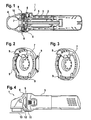
Fig. 1 einen Schnitt durch einen Winkelschleifer mit einem Motorgehäuse und einem Getriebegehäuse und einem im Übergangsbereich der Gehäuseteile angeordneten, zweiteiligen Luftleitelement, bestehend aus einem Luftleitring und einer Luftleitscheibe, wobei an der Luftleitscheibe Funktionsabschnitte angeordnet sind, die durch Ausnehmungen in der Wandung des Getriebegehäuses hindurchragen und dadurch einen Teil der äußeren Mantelfläche des Gehäuses bilden, -
Fig. 2 eine Luftleitscheibe in perspektivischer Einzeldarstellung mit insgesamt vier über den Umfang verteilten Funktionsabschnitten, -
Fig. 3 eine Luftleitscheibe perspektivischer Einzeldarstellung, mit lediglich zwei Funktionsabschnitten auf gegenüberliegenden Seiten des Umfangs, -
Fig. 4 eine Seitenansicht eines Winkelschleifers mit einem Funktionsabschnitt eines Luftleitelementes, das durch eine Ausnehmung im Getriebegehäuse hindurchragt, -
Fig. 5 bis 7 verschiedene Ansichten eines Winkelschleifers mit einem einzigen, seitlich über das Getriebegehäuse herausragenden Funktionsabschnitt eines Luftleitelementes zum Schutz eines Ein-/Aus-Schalters der Werkzeugmaschine, -
Fig. 8 bis 11 ein weiteres Ausführungsbeispiel eines Winkelschleifers mit einer Ausführung des Funktionsabschnittes des Luftleitelementes als Dämpfungselement zwischen Motorgehäuse und Getriebegehäuse, -
Fig. 12 bis 14 ein weiteres Ausführungsbeispiel, bei dem insgesamt drei Funktionsabschnitte am Luftleitelement vorgesehen sind und über das Gehäuse überstehen, wodurch ein Abrutschschutz gegeben ist, -
Fig. 15 und 16 ein weiteres Ausführungsbeispiel, bei dem der Funktionsabschnitt des Luftleitelementes die Aufgabe einer Verdrehsicherung übernimmt, -
Fig. 17 bis 19 ein weiteres Ausführungsbeispiel, bei dem das Funktionselement ebenfalls als Verdrehsicherung wirkt, jedoch mit einem verstellbaren Hebel zusammenwirkt, -
Fig. 20 ein weiteres Ausführungsbeispiel, bei dem verschiedene Funktionsabschnitte des Luftleitelementes die Aufgabe eine Piktogrammes übernehmen, um dem Anwender einen Hinweis auf verschiedene Aufgaben der Werkzeugmaschine bei verschiedenen Winkelpositionen des Getriebegehäuses gegenüber dem Motorgehäuse zu geben, -
Fig. 21 ein weiteres Ausführungsbeispiel, bei dem die Funktionsabschnitte die Aufgabe eines zusätzlichen Luftauslasses haben, -
Fig. 22 ein weiteres Ausführungsbeispiel, bei dem zwei oben liegende Funktionsabschnitte die Aufgabe eines Abstandselementes bzw. Pins übernehmen, um ein sicheres Ablegen des Winkelschleifers auf dem Geräterücken zu ermöglichen, -
Fig. 23 ein weiteres Ausführungsbeispiel, bei dem ein einzelner Funktionsabschnitt auf der Oberseite des Gehäuses mit einer Öse versehen ist, die beispielsweise zum Ablegen oder zum Sichern des Werkzeuges genutzt werden kann.
-
Fig. 1 a section through an angle grinder with a motor housing and a gear housing and arranged in the transition region of the housing parts, two-part air guide element, consisting of an air guide ring and a Luftleitscheibe, wherein functional sections are arranged on the air deflector, which protrude through recesses in the wall of the transmission housing and thereby a Form part of the outer surface of the housing, -
Fig. 2 an air guide disc in perspective detail view with a total of four distributed over the circumference functional sections, -
Fig. 3 an air guide disc perspective single representation, with only two functional sections on opposite sides of the circumference, -
Fig. 4 a side view of an angle grinder with a functional portion of an air guide element, which protrudes through a recess in the transmission housing, -
Fig. 5 to 7 various views of an angle grinder with a single, laterally projecting beyond the gear housing functional portion of an air guide element for protecting an on / off switch of the machine tool, -
8 to 11 a further embodiment of an angle grinder with an embodiment of the functional portion of the air guide element as a damping element between the motor housing and the gear housing, -
Fig. 12 to 14 a further embodiment in which a total of three functional sections are provided on the air guide element and project beyond the housing, whereby a slip protection is given, -
FIGS. 15 and 16 a further embodiment in which the functional portion of the air guide element takes over the task of a rotation, -
17 to 19 a further embodiment in which the functional element also acts as anti-rotation, but interacts with an adjustable lever, -
Fig. 20 a further embodiment, in which different functional sections of the air guide take over the task of a pictogram to give the user an indication of various tasks of the machine tool at different angular positions of the gear housing relative to the motor housing, -
Fig. 21 a further embodiment in which the functional sections have the task of an additional air outlet, -
Fig. 22 a further embodiment in which two upper-lying functional sections take on the task of a spacer element or pins in order to enable a safe depositing of the angle grinder on the device back, -
Fig. 23 a further embodiment in which a single functional portion is provided on the upper side of the housing with an eyelet, which can be used for example for storing or for securing the tool.
In den Figuren sind gleiche Bauteile mit gleichen Bezugszeichen versehen.In the figures, the same components are provided with the same reference numerals.
Bei der in
An der Luftleitscheibe 7 im Getriebegehäuse 4 sind einteilig ausgebildete Funktionsabschnitte 9 vorgesehen, die in eine Ausnehmung in der Wandung des Getriebegehäuses 4 einragen. Diese Funktionsabschnitte 9 können über die Luftleitfunktion hinausgehend zusätzliche Aufgaben übernehmen, die im Folgenden anhand der weiteren Figuren dargestellt werden. Die nach außen gewandte Seite der Funktionsabschnitte 9 bilden einen Teil der äußeren Mantelfläche 10 der Werkzeugmaschine. Möglich ist sowohl ein bündiges bzw. flächiges Abschließen mit den umgebenden Mantelflächenbereichen als auch eine erhabene Ausbildung der Funktionsabschnitte 9 bzw. ein Zurückversetzen in der Ausnehmung im Gehäuse, so dass in diesem Bereich die Mantelfläche vertieft ist.On the
Wie den perspektivischen Darstellungen einer Luftleitscheibe 7 in den
Der Seitenansicht nach
Des Weiteren ist in
Der Funktionsabschnitt 9 übernimmt im Ausführungsbeispiel nach
Im Ausführungsbeispiel gemäß den
Der Funktionsabschnitt 9 ist einteilig mit dem Luftleitelement ausgebildet und besteht insbesondere aus dem gleichen Material wie das Luftleitelement. Möglich ist aber auch eine Komposit-Ausführung, bei der der Funktionsabschnitt aus einem anderen Material gefertigt ist als die sonstigen Teile des Luftleitelementes. Beispielsweise kann für die Aufgabe des Schalterschutzes der Funktionsabschnitt aus einem weicheren Material gefertigt sein, beispielsweise aus Gummi oder einem gummiähnlichen Material, um im Falle eines Herabfallens der Handwerkzeugmaschine ein Abpuffern des Stoßes zu ermöglichen.The
In den
Gemäß den
In der Ausführungsvariante gemäß
In der Ausführungsvariante gemäß
Im Ausführungsbeispiel gemäß den
In den
Ein weiteres Beispiel einer Verdrehsicherung findet sich in den
Im Ausführungsbeispiel nach
Im Ausführungsbeispiel nach
Im Ausführungsbeispiel nach
Im Ausführungsbeispiel nach
Claims (10)
- Power tool, in particular a portable power tool such as an angle grinder (1), comprising a drive motor (2) driving a tool (13) and comprising an air guide element (6) which is arranged in the two-part housing of the power tool (1) and directs an air flow (5) passing over the drive motor (2) to the outside, wherein the air guide element (6) has a functional section (9) which forms part of the outer lateral surface (10) of the power tool, characterized in that the air guide element (6) is of two-piece construction and comprises an air guide ring (8) and an air guide disc (7), in that the functional section (9) of the air guide element (6) is arranged between the housing parts (3, 4) or adjacent to the parting line (11) between the housing parts (3, 4), and in that the air guide ring (8) is arranged in the first housing part (3) and the air guide disc (7) is arranged in the second housing part (4).
- Power tool according to Claim 1, characterized in that the functional section (9) projects through a recess (12) in the housing.
- Power tool according to Claim 1 or 2, characterized in that the functional section (9) fits into the lateral surface (10) of the housing.
- Power tool according to one of Claims 1 to 3, characterized in that the functional section (9) projects beyond the lateral surface (10) of the housing.
- Power tool according to one of Claims 1 to 4, characterized in that the air guide ring (8) is in contact with the air guide disc (7).
- Power tool according to one of Claims 1 to 5, characterized in that a plurality of functional sections (9) projecting into the lateral surface (10) or forming the lateral surface (10) are provided in a distributed manner over the circumference.
- Power tool according to one of Claims 1 to 6, characterized in that the housing parts are formed by a motor housing (3) which accommodates the drive motor (2) and by a transmission housing (4) which accommodates a transmission.
- Power tool according to one of Claims 1 to 7, characterized in that the functional section (9) is designed as an anti-rotation locking element between the housing parts (3, 4).
- Power tool according to one of Claims 1 to 8, characterized in that the functional section (9) is embodied as a damping element and is in particular of annular design.
- Power tool according to one of Claims 1 to 9, characterized in that the functional section (9) is designed as an air outlet element and has an air outlet opening (16).
Applications Claiming Priority (2)
| Application Number | Priority Date | Filing Date | Title |
|---|---|---|---|
| DE102007017243A DE102007017243A1 (en) | 2007-04-12 | 2007-04-12 | Machine tool, in particular hand tool |
| PCT/EP2008/051649 WO2008125368A1 (en) | 2007-04-12 | 2008-02-12 | Machine tool, particularly hand machine tool |
Publications (3)
| Publication Number | Publication Date |
|---|---|
| EP2146820A1 EP2146820A1 (en) | 2010-01-27 |
| EP2146820B1 true EP2146820B1 (en) | 2011-07-13 |
| EP2146820B2 EP2146820B2 (en) | 2019-10-16 |
Family
ID=39431175
Family Applications (1)
| Application Number | Title | Priority Date | Filing Date |
|---|---|---|---|
| EP08708891.0A Active EP2146820B2 (en) | 2007-04-12 | 2008-02-12 | Machine tool, particularly hand machine tool |
Country Status (7)
| Country | Link |
|---|---|
| US (1) | US8113922B2 (en) |
| EP (1) | EP2146820B2 (en) |
| CN (1) | CN101657297B (en) |
| AT (1) | ATE516112T1 (en) |
| DE (1) | DE102007017243A1 (en) |
| RU (1) | RU2472607C2 (en) |
| WO (1) | WO2008125368A1 (en) |
Families Citing this family (31)
| Publication number | Priority date | Publication date | Assignee | Title |
|---|---|---|---|---|
| DE102008059599A1 (en) * | 2008-11-28 | 2010-06-02 | Aeg Electric Tools Gmbh | power tool |
| DE102008063510A1 (en) | 2008-12-10 | 2010-06-17 | Flex-Elektrowerkzeuge Gmbh | Hand-held machine tool |
| EP2391480B2 (en) * | 2009-01-30 | 2018-08-15 | Koki Holdings Kabushiki Kaisha | Power tool |
| DE102009026519A1 (en) | 2009-05-27 | 2010-12-02 | Robert Bosch Gmbh | Machine tool, in particular hand tool |
| DE102009026516A1 (en) | 2009-05-27 | 2010-12-02 | Robert Bosch Gmbh | Machine tool, in particular hand tool |
| JP5395531B2 (en) * | 2009-06-19 | 2014-01-22 | 株式会社マキタ | Work tools |
| DE202011001475U1 (en) * | 2011-01-13 | 2011-03-17 | Metabowerke Gmbh | Power tool, in particular a grinding or polishing machine |
| US8348727B2 (en) * | 2011-05-26 | 2013-01-08 | Black & Decker Inc. | Airflow arrangement for a power tool |
| DE102012103603A1 (en) * | 2012-04-24 | 2013-10-24 | C. & E. Fein Gmbh | Handleable machine tool with fan device |
| US20130299207A1 (en) * | 2012-05-10 | 2013-11-14 | Black & Decker, Inc. | Power tool cooling |
| DE102012223897A1 (en) * | 2012-12-20 | 2014-06-26 | Robert Bosch Gmbh | Hand-held power tool i.e. angle sander, has cooling device arranged for refrigerating drive unit and electronic unit and provided with memory unit for active storage of thermal energy in form of energy |
| DE102013219450A1 (en) * | 2013-09-26 | 2015-03-26 | Robert Bosch Gmbh | Battery operated eccentric sander with an electronically commutated electric motor |
| US20150151424A1 (en) | 2013-10-29 | 2015-06-04 | Black & Decker Inc. | Power tool with ergonomic handgrip |
| USD725981S1 (en) | 2013-10-29 | 2015-04-07 | Black & Decker Inc. | Screwdriver with nosepiece |
| US9954418B2 (en) * | 2014-03-17 | 2018-04-24 | Makita Corporation | Power tool |
| US9821433B2 (en) * | 2014-05-20 | 2017-11-21 | Black & Decker Inc. | Particle separation assembly for power tool |
| DE102014210915A1 (en) * | 2014-06-06 | 2015-12-17 | Robert Bosch Gmbh | Power tool |
| US9475172B2 (en) | 2014-07-15 | 2016-10-25 | Milwaukee Electric Tool Corporation | Adjustable guard for power tool |
| GB201413008D0 (en) * | 2014-07-23 | 2014-09-03 | Black & Decker Inc | A range of power tools |
| DE102015111717A1 (en) * | 2015-07-20 | 2017-01-26 | Metabowerke Gmbh | Luftleitscheibe |
| JP6646373B2 (en) * | 2015-07-23 | 2020-02-14 | 京セラインダストリアルツールズ株式会社 | Hand-held power tool |
| US10661426B2 (en) * | 2016-02-19 | 2020-05-26 | Makita Corporation | Work tool with vibration dampers |
| DE102016210853A1 (en) * | 2016-06-17 | 2017-12-21 | Robert Bosch Gmbh | Hand tool with a cooling unit |
| DE202018104460U1 (en) * | 2017-09-29 | 2018-08-16 | Nanjing Chervon Industry Co., Ltd. | Electric hand tool |
| DE102018208048A1 (en) * | 2018-05-23 | 2019-11-28 | Robert Bosch Gmbh | Hand tool |
| EP3603898B1 (en) * | 2018-08-03 | 2021-04-14 | Andreas Stihl AG & Co. KG | Manually operated work device |
| DE102018217155A1 (en) * | 2018-10-08 | 2020-04-09 | Robert Bosch Gmbh | Hand tool |
| JP7210261B2 (en) | 2018-12-14 | 2023-01-23 | 株式会社マキタ | ELECTRIC WORKING MACHINE AND METHOD FOR MANUFACTURING STATOR IN MOTOR FOR ELECTRIC WORKING MACHINE |
| SE543413C2 (en) * | 2019-05-03 | 2021-01-05 | Husqvarna Ab | Hand-held electrically powered device |
| DE202019106967U1 (en) * | 2019-12-13 | 2021-03-16 | C. & E. Fein Gmbh | Electric hand tool |
| DE102020214817A1 (en) * | 2019-12-30 | 2021-07-01 | Robert Bosch Gesellschaft mit beschränkter Haftung | Machine tool and method for cooling a drive unit of the machine tool |
Family Cites Families (17)
| Publication number | Priority date | Publication date | Assignee | Title |
|---|---|---|---|---|
| NL277215A (en) † | 1961-04-14 | |||
| US3829721A (en) * | 1973-07-30 | 1974-08-13 | Black & Decker Mfg Co | Air flow baffle construction for electric motor devices |
| DE2910845A1 (en) * | 1979-03-20 | 1980-10-02 | Bosch Gmbh Robert | ELECTRICALLY DRIVED HAND TOOL, ESPECIALLY DRILLING MACHINE |
| US4905772A (en) * | 1988-09-01 | 1990-03-06 | Honsa Thomas W | Rotary power tool with vibration damping |
| DE4003029A1 (en) * | 1990-02-02 | 1991-08-08 | Bosch Gmbh Robert | HANDMADE MACHINE TOOL WITH A RADIAL BLOWER |
| DE4220078A1 (en) * | 1992-06-19 | 1993-12-23 | Bosch Gmbh Robert | Hand tool |
| DE29501974U1 (en) | 1995-02-08 | 1996-06-05 | Bosch Gmbh Robert | Electric hand machine tool |
| DE29513331U1 (en) * | 1995-08-19 | 1996-12-12 | Bosch Gmbh Robert | Angle grinder protection hood |
| ATE287319T1 (en) * | 1998-12-31 | 2005-02-15 | Fein C & E Gmbh | POWER TOOLS, ESPECIALLY ANGLE GRINDERS |
| DE19924552A1 (en) * | 1999-05-28 | 2000-11-30 | Hilti Ag | Electrically powered hand device e.g. electric screwdriver, has cooling air channel arranged downstream of electric motor and gearbox with outflow openings arranged to direct heated air away from user |
| CN1136491C (en) * | 2000-11-23 | 2004-01-28 | 厦门资盛科技发展有限公司 | Multiplexing interface card for operating single computer by more users |
| DE10248921A1 (en) | 2002-10-17 | 2004-05-13 | C. & E. Fein Gmbh & Co Kg | Electric tool e.g. edge grinder, with universal motor drive having self-supporting stator with support parts at its ends supporting motor shaft and motor brushes |
| DE10261572A1 (en) * | 2002-12-23 | 2004-07-01 | Robert Bosch Gmbh | Electric hand tool machine e.g. drill, has arrangement for generating additional cooling air flow that passes at least one machine component outside or in low flow region of cooling air flow |
| JP4731162B2 (en) † | 2004-12-27 | 2011-07-20 | 株式会社マキタ | Electric tool |
| JP4575223B2 (en) * | 2005-04-20 | 2010-11-04 | 株式会社マキタ | Rotating tool |
| US7988538B2 (en) * | 2006-10-13 | 2011-08-02 | Black & Decker Inc. | Large angle grinder |
| US7770660B2 (en) * | 2007-11-21 | 2010-08-10 | Black & Decker Inc. | Mid-handle drill construction and assembly process |
-
2007
- 2007-04-12 DE DE102007017243A patent/DE102007017243A1/en not_active Withdrawn
-
2008
- 2008-02-12 RU RU2009141525/02A patent/RU2472607C2/en active
- 2008-02-12 AT AT08708891T patent/ATE516112T1/en active
- 2008-02-12 EP EP08708891.0A patent/EP2146820B2/en active Active
- 2008-02-12 US US12/307,649 patent/US8113922B2/en active Active
- 2008-02-12 WO PCT/EP2008/051649 patent/WO2008125368A1/en active Application Filing
- 2008-02-12 CN CN2008800118576A patent/CN101657297B/en active Active
Also Published As
| Publication number | Publication date |
|---|---|
| US8113922B2 (en) | 2012-02-14 |
| US20090280732A1 (en) | 2009-11-12 |
| RU2009141525A (en) | 2011-05-20 |
| CN101657297A (en) | 2010-02-24 |
| ATE516112T1 (en) | 2011-07-15 |
| EP2146820A1 (en) | 2010-01-27 |
| EP2146820B2 (en) | 2019-10-16 |
| CN101657297B (en) | 2013-03-06 |
| DE102007017243A1 (en) | 2008-10-16 |
| WO2008125368A1 (en) | 2008-10-23 |
| RU2472607C2 (en) | 2013-01-20 |
Similar Documents
| Publication | Publication Date | Title |
|---|---|---|
| EP2146820B1 (en) | Machine tool, particularly hand machine tool | |
| EP2101957B1 (en) | Electric device with locked-on rotatable operating element | |
| EP2086372B2 (en) | Drive apparatus for mobile furniture parts | |
| EP3389951B1 (en) | Battery operated handheld machine tool i | |
| EP2944433A1 (en) | Manual machine tool | |
| DE102012212803A1 (en) | Hand tool Auxiliary handle | |
| DE102016111028A1 (en) | Dust collecting cover for cutting devices | |
| DE102016111548A1 (en) | processing device | |
| EP2476520B1 (en) | Electric machine tool, in particular a grinding or polishing machine | |
| EP2677910A1 (en) | Tool and drive device for a motor driven kitchen appliance | |
| EP3845341B1 (en) | Handheld machine tool with finger protection | |
| EP2818279A2 (en) | Sanding plate for an oscillation drive | |
| DE102005063016A1 (en) | Hand tool with Drehgriffverstelleinrichtung | |
| EP3389952B1 (en) | Battery operated machine tool iii | |
| EP2125279B1 (en) | Pipe disconnecting device | |
| DE102008000732A1 (en) | Hand tool, in particular hand-guided grinding machine | |
| EP1749620B1 (en) | Fixing mechanism for an attachment for a hand-held machine tool | |
| EP2853665A2 (en) | Door handle | |
| EP2659816B1 (en) | Nozzle for a floor cleaning machine | |
| EP0458080B1 (en) | Hand operated electrical machine tool | |
| DE10318324A1 (en) | Portable hand-guided edge cutter has two wheels either side of gear housing and coaxial relative to output shaft to protect gear housing from wear on ground | |
| DE102015111717A1 (en) | Luftleitscheibe | |
| WO2020177805A1 (en) | Torque tool | |
| DE102008026065B4 (en) | Hand tool with swivel handle | |
| DE102005010876A1 (en) | Circular grinding disc has rear face with ribbed air intake ducts discharging through outlets |
Legal Events
| Date | Code | Title | Description |
|---|---|---|---|
| PUAI | Public reference made under article 153(3) epc to a published international application that has entered the european phase |
Free format text: ORIGINAL CODE: 0009012 |
|
| 17P | Request for examination filed |
Effective date: 20091112 |
|
| AK | Designated contracting states |
Kind code of ref document: A1 Designated state(s): AT BE BG CH CY CZ DE DK EE ES FI FR GB GR HR HU IE IS IT LI LT LU LV MC MT NL NO PL PT RO SE SI SK TR |
|
| AX | Request for extension of the european patent |
Extension state: AL BA MK RS |
|
| DAX | Request for extension of the european patent (deleted) | ||
| 17Q | First examination report despatched |
Effective date: 20100716 |
|
| GRAP | Despatch of communication of intention to grant a patent |
Free format text: ORIGINAL CODE: EPIDOSNIGR1 |
|
| GRAS | Grant fee paid |
Free format text: ORIGINAL CODE: EPIDOSNIGR3 |
|
| GRAA | (expected) grant |
Free format text: ORIGINAL CODE: 0009210 |
|
| AK | Designated contracting states |
Kind code of ref document: B1 Designated state(s): AT BE BG CH CY CZ DE DK EE ES FI FR GB GR HR HU IE IS IT LI LT LU LV MC MT NL NO PL PT RO SE SI SK TR |
|
| REG | Reference to a national code |
Ref country code: GB Ref legal event code: FG4D Free format text: NOT ENGLISH |
|
| REG | Reference to a national code |
Ref country code: CH Ref legal event code: EP |
|
| REG | Reference to a national code |
Ref country code: IE Ref legal event code: FG4D Free format text: LANGUAGE OF EP DOCUMENT: GERMAN |
|
| REG | Reference to a national code |
Ref country code: DE Ref legal event code: R096 Ref document number: 502008004187 Country of ref document: DE Effective date: 20110908 |
|
| REG | Reference to a national code |
Ref country code: NL Ref legal event code: VDEP Effective date: 20110713 |
|
| PG25 | Lapsed in a contracting state [announced via postgrant information from national office to epo] |
Ref country code: PT Free format text: LAPSE BECAUSE OF FAILURE TO SUBMIT A TRANSLATION OF THE DESCRIPTION OR TO PAY THE FEE WITHIN THE PRESCRIBED TIME-LIMIT Effective date: 20111114 Ref country code: LT Free format text: LAPSE BECAUSE OF FAILURE TO SUBMIT A TRANSLATION OF THE DESCRIPTION OR TO PAY THE FEE WITHIN THE PRESCRIBED TIME-LIMIT Effective date: 20110713 Ref country code: IS Free format text: LAPSE BECAUSE OF FAILURE TO SUBMIT A TRANSLATION OF THE DESCRIPTION OR TO PAY THE FEE WITHIN THE PRESCRIBED TIME-LIMIT Effective date: 20111113 Ref country code: NO Free format text: LAPSE BECAUSE OF FAILURE TO SUBMIT A TRANSLATION OF THE DESCRIPTION OR TO PAY THE FEE WITHIN THE PRESCRIBED TIME-LIMIT Effective date: 20111013 Ref country code: FI Free format text: LAPSE BECAUSE OF FAILURE TO SUBMIT A TRANSLATION OF THE DESCRIPTION OR TO PAY THE FEE WITHIN THE PRESCRIBED TIME-LIMIT Effective date: 20110713 Ref country code: HR Free format text: LAPSE BECAUSE OF FAILURE TO SUBMIT A TRANSLATION OF THE DESCRIPTION OR TO PAY THE FEE WITHIN THE PRESCRIBED TIME-LIMIT Effective date: 20110713 Ref country code: NL Free format text: LAPSE BECAUSE OF FAILURE TO SUBMIT A TRANSLATION OF THE DESCRIPTION OR TO PAY THE FEE WITHIN THE PRESCRIBED TIME-LIMIT Effective date: 20110713 Ref country code: SE Free format text: LAPSE BECAUSE OF FAILURE TO SUBMIT A TRANSLATION OF THE DESCRIPTION OR TO PAY THE FEE WITHIN THE PRESCRIBED TIME-LIMIT Effective date: 20110713 |
|
| REG | Reference to a national code |
Ref country code: IE Ref legal event code: FD4D |
|
| PG25 | Lapsed in a contracting state [announced via postgrant information from national office to epo] |
Ref country code: CY Free format text: LAPSE BECAUSE OF FAILURE TO SUBMIT A TRANSLATION OF THE DESCRIPTION OR TO PAY THE FEE WITHIN THE PRESCRIBED TIME-LIMIT Effective date: 20110713 Ref country code: SI Free format text: LAPSE BECAUSE OF FAILURE TO SUBMIT A TRANSLATION OF THE DESCRIPTION OR TO PAY THE FEE WITHIN THE PRESCRIBED TIME-LIMIT Effective date: 20110713 Ref country code: LV Free format text: LAPSE BECAUSE OF FAILURE TO SUBMIT A TRANSLATION OF THE DESCRIPTION OR TO PAY THE FEE WITHIN THE PRESCRIBED TIME-LIMIT Effective date: 20110713 Ref country code: GR Free format text: LAPSE BECAUSE OF FAILURE TO SUBMIT A TRANSLATION OF THE DESCRIPTION OR TO PAY THE FEE WITHIN THE PRESCRIBED TIME-LIMIT Effective date: 20111014 Ref country code: PL Free format text: LAPSE BECAUSE OF FAILURE TO SUBMIT A TRANSLATION OF THE DESCRIPTION OR TO PAY THE FEE WITHIN THE PRESCRIBED TIME-LIMIT Effective date: 20110713 |
|
| PLBI | Opposition filed |
Free format text: ORIGINAL CODE: 0009260 |
|
| PG25 | Lapsed in a contracting state [announced via postgrant information from national office to epo] |
Ref country code: SK Free format text: LAPSE BECAUSE OF FAILURE TO SUBMIT A TRANSLATION OF THE DESCRIPTION OR TO PAY THE FEE WITHIN THE PRESCRIBED TIME-LIMIT Effective date: 20110713 Ref country code: CZ Free format text: LAPSE BECAUSE OF FAILURE TO SUBMIT A TRANSLATION OF THE DESCRIPTION OR TO PAY THE FEE WITHIN THE PRESCRIBED TIME-LIMIT Effective date: 20110713 Ref country code: IE Free format text: LAPSE BECAUSE OF FAILURE TO SUBMIT A TRANSLATION OF THE DESCRIPTION OR TO PAY THE FEE WITHIN THE PRESCRIBED TIME-LIMIT Effective date: 20110713 |
|
| PLAX | Notice of opposition and request to file observation + time limit sent |
Free format text: ORIGINAL CODE: EPIDOSNOBS2 |
|
| 26 | Opposition filed |
Opponent name: METABOWERKE GMBH Effective date: 20120413 |
|
| PG25 | Lapsed in a contracting state [announced via postgrant information from national office to epo] |
Ref country code: RO Free format text: LAPSE BECAUSE OF FAILURE TO SUBMIT A TRANSLATION OF THE DESCRIPTION OR TO PAY THE FEE WITHIN THE PRESCRIBED TIME-LIMIT Effective date: 20110713 Ref country code: EE Free format text: LAPSE BECAUSE OF FAILURE TO SUBMIT A TRANSLATION OF THE DESCRIPTION OR TO PAY THE FEE WITHIN THE PRESCRIBED TIME-LIMIT Effective date: 20110713 Ref country code: IT Free format text: LAPSE BECAUSE OF FAILURE TO SUBMIT A TRANSLATION OF THE DESCRIPTION OR TO PAY THE FEE WITHIN THE PRESCRIBED TIME-LIMIT Effective date: 20110713 |
|
| PG25 | Lapsed in a contracting state [announced via postgrant information from national office to epo] |
Ref country code: DK Free format text: LAPSE BECAUSE OF FAILURE TO SUBMIT A TRANSLATION OF THE DESCRIPTION OR TO PAY THE FEE WITHIN THE PRESCRIBED TIME-LIMIT Effective date: 20110713 |
|
| REG | Reference to a national code |
Ref country code: DE Ref legal event code: R026 Ref document number: 502008004187 Country of ref document: DE Effective date: 20120413 |
|
| BERE | Be: lapsed |
Owner name: ROBERT BOSCH G.M.B.H. Effective date: 20120228 |
|
| PG25 | Lapsed in a contracting state [announced via postgrant information from national office to epo] |
Ref country code: MC Free format text: LAPSE BECAUSE OF NON-PAYMENT OF DUE FEES Effective date: 20120229 |
|
| REG | Reference to a national code |
Ref country code: CH Ref legal event code: PL |
|
| PLBB | Reply of patent proprietor to notice(s) of opposition received |
Free format text: ORIGINAL CODE: EPIDOSNOBS3 |
|
| PG25 | Lapsed in a contracting state [announced via postgrant information from national office to epo] |
Ref country code: LI Free format text: LAPSE BECAUSE OF NON-PAYMENT OF DUE FEES Effective date: 20120229 Ref country code: CH Free format text: LAPSE BECAUSE OF NON-PAYMENT OF DUE FEES Effective date: 20120229 |
|
| PG25 | Lapsed in a contracting state [announced via postgrant information from national office to epo] |
Ref country code: BE Free format text: LAPSE BECAUSE OF NON-PAYMENT OF DUE FEES Effective date: 20120228 |
|
| PG25 | Lapsed in a contracting state [announced via postgrant information from national office to epo] |
Ref country code: ES Free format text: LAPSE BECAUSE OF FAILURE TO SUBMIT A TRANSLATION OF THE DESCRIPTION OR TO PAY THE FEE WITHIN THE PRESCRIBED TIME-LIMIT Effective date: 20111024 |
|
| PG25 | Lapsed in a contracting state [announced via postgrant information from national office to epo] |
Ref country code: BG Free format text: LAPSE BECAUSE OF FAILURE TO SUBMIT A TRANSLATION OF THE DESCRIPTION OR TO PAY THE FEE WITHIN THE PRESCRIBED TIME-LIMIT Effective date: 20111013 |
|
| PG25 | Lapsed in a contracting state [announced via postgrant information from national office to epo] |
Ref country code: MT Free format text: LAPSE BECAUSE OF FAILURE TO SUBMIT A TRANSLATION OF THE DESCRIPTION OR TO PAY THE FEE WITHIN THE PRESCRIBED TIME-LIMIT Effective date: 20110713 |
|
| REG | Reference to a national code |
Ref country code: AT Ref legal event code: MM01 Ref document number: 516112 Country of ref document: AT Kind code of ref document: T Effective date: 20130212 |
|
| PG25 | Lapsed in a contracting state [announced via postgrant information from national office to epo] |
Ref country code: TR Free format text: LAPSE BECAUSE OF FAILURE TO SUBMIT A TRANSLATION OF THE DESCRIPTION OR TO PAY THE FEE WITHIN THE PRESCRIBED TIME-LIMIT Effective date: 20110713 |
|
| PG25 | Lapsed in a contracting state [announced via postgrant information from national office to epo] |
Ref country code: LU Free format text: LAPSE BECAUSE OF NON-PAYMENT OF DUE FEES Effective date: 20120212 Ref country code: AT Free format text: LAPSE BECAUSE OF NON-PAYMENT OF DUE FEES Effective date: 20130212 |
|
| PG25 | Lapsed in a contracting state [announced via postgrant information from national office to epo] |
Ref country code: HU Free format text: LAPSE BECAUSE OF FAILURE TO SUBMIT A TRANSLATION OF THE DESCRIPTION OR TO PAY THE FEE WITHIN THE PRESCRIBED TIME-LIMIT Effective date: 20080212 |
|
| APAH | Appeal reference modified |
Free format text: ORIGINAL CODE: EPIDOSCREFNO |
|
| APBM | Appeal reference recorded |
Free format text: ORIGINAL CODE: EPIDOSNREFNO |
|
| APBP | Date of receipt of notice of appeal recorded |
Free format text: ORIGINAL CODE: EPIDOSNNOA2O |
|
| APBM | Appeal reference recorded |
Free format text: ORIGINAL CODE: EPIDOSNREFNO |
|
| APBP | Date of receipt of notice of appeal recorded |
Free format text: ORIGINAL CODE: EPIDOSNNOA2O |
|
| APBQ | Date of receipt of statement of grounds of appeal recorded |
Free format text: ORIGINAL CODE: EPIDOSNNOA3O |
|
| APBQ | Date of receipt of statement of grounds of appeal recorded |
Free format text: ORIGINAL CODE: EPIDOSNNOA3O |
|
| REG | Reference to a national code |
Ref country code: FR Ref legal event code: PLFP Year of fee payment: 9 |
|
| REG | Reference to a national code |
Ref country code: FR Ref legal event code: PLFP Year of fee payment: 10 |
|
| REG | Reference to a national code |
Ref country code: FR Ref legal event code: PLFP Year of fee payment: 11 |
|
| PLBP | Opposition withdrawn |
Free format text: ORIGINAL CODE: 0009264 |
|
| APBU | Appeal procedure closed |
Free format text: ORIGINAL CODE: EPIDOSNNOA9O |
|
| PUAH | Patent maintained in amended form |
Free format text: ORIGINAL CODE: 0009272 |
|
| STAA | Information on the status of an ep patent application or granted ep patent |
Free format text: STATUS: PATENT MAINTAINED AS AMENDED |
|
| 27A | Patent maintained in amended form |
Effective date: 20191016 |
|
| AK | Designated contracting states |
Kind code of ref document: B2 Designated state(s): AT BE BG CH CY CZ DE DK EE ES FI FR GB GR HR HU IE IS IT LI LT LU LV MC MT NL NO PL PT RO SE SI SK TR |
|
| REG | Reference to a national code |
Ref country code: DE Ref legal event code: R102 Ref document number: 502008004187 Country of ref document: DE |
|
| PGFP | Annual fee paid to national office [announced via postgrant information from national office to epo] |
Ref country code: GB Payment date: 20200225 Year of fee payment: 13 |
|
| GBPC | Gb: european patent ceased through non-payment of renewal fee |
Effective date: 20210212 |
|
| PG25 | Lapsed in a contracting state [announced via postgrant information from national office to epo] |
Ref country code: GB Free format text: LAPSE BECAUSE OF NON-PAYMENT OF DUE FEES Effective date: 20210212 |
|
| PGFP | Annual fee paid to national office [announced via postgrant information from national office to epo] |
Ref country code: FR Payment date: 20230220 Year of fee payment: 16 |
|
| P01 | Opt-out of the competence of the unified patent court (upc) registered |
Effective date: 20230509 |
|
| PGFP | Annual fee paid to national office [announced via postgrant information from national office to epo] |
Ref country code: DE Payment date: 20230426 Year of fee payment: 16 |