EP3034277A1 - Bonded body and bonding method - Google Patents
Bonded body and bonding method Download PDFInfo
- Publication number
- EP3034277A1 EP3034277A1 EP14836080.3A EP14836080A EP3034277A1 EP 3034277 A1 EP3034277 A1 EP 3034277A1 EP 14836080 A EP14836080 A EP 14836080A EP 3034277 A1 EP3034277 A1 EP 3034277A1
- Authority
- EP
- European Patent Office
- Prior art keywords
- bonding
- bonding layer
- bonded
- bonded body
- mpa
- Prior art date
- Legal status (The legal status is an assumption and is not a legal conclusion. Google has not performed a legal analysis and makes no representation as to the accuracy of the status listed.)
- Granted
Links
- 238000000034 method Methods 0.000 title claims description 50
- 239000000463 material Substances 0.000 claims abstract description 60
- 239000011800 void material Substances 0.000 claims abstract description 9
- 229910052751 metal Inorganic materials 0.000 claims description 43
- 239000002184 metal Substances 0.000 claims description 43
- 238000001746 injection moulding Methods 0.000 claims description 36
- 239000011347 resin Substances 0.000 claims description 34
- 229920005989 resin Polymers 0.000 claims description 34
- 229920001971 elastomer Polymers 0.000 claims description 31
- 238000003466 welding Methods 0.000 claims description 30
- 239000000806 elastomer Substances 0.000 claims description 29
- 239000011148 porous material Substances 0.000 claims description 25
- XLYOFNOQVPJJNP-UHFFFAOYSA-N water Substances O XLYOFNOQVPJJNP-UHFFFAOYSA-N 0.000 claims description 25
- 238000010521 absorption reaction Methods 0.000 claims description 16
- 239000011521 glass Substances 0.000 claims description 15
- 238000004381 surface treatment Methods 0.000 claims description 4
- 238000010030 laminating Methods 0.000 claims description 3
- 238000012360 testing method Methods 0.000 description 28
- 230000000694 effects Effects 0.000 description 14
- 230000000052 comparative effect Effects 0.000 description 13
- 229910052782 aluminium Inorganic materials 0.000 description 12
- XAGFODPZIPBFFR-UHFFFAOYSA-N aluminium Chemical compound [Al] XAGFODPZIPBFFR-UHFFFAOYSA-N 0.000 description 12
- 230000001066 destructive effect Effects 0.000 description 12
- 230000014759 maintenance of location Effects 0.000 description 9
- 239000000919 ceramic Substances 0.000 description 8
- 239000000126 substance Substances 0.000 description 8
- 238000002844 melting Methods 0.000 description 7
- 230000008018 melting Effects 0.000 description 7
- 230000003247 decreasing effect Effects 0.000 description 6
- NLKNQRATVPKPDG-UHFFFAOYSA-M potassium iodide Chemical compound [K+].[I-] NLKNQRATVPKPDG-UHFFFAOYSA-M 0.000 description 6
- 230000015572 biosynthetic process Effects 0.000 description 5
- 230000035939 shock Effects 0.000 description 5
- 229920002302 Nylon 6,6 Polymers 0.000 description 4
- PPBRXRYQALVLMV-UHFFFAOYSA-N Styrene Chemical compound C=CC1=CC=CC=C1 PPBRXRYQALVLMV-UHFFFAOYSA-N 0.000 description 4
- WNLRTRBMVRJNCN-UHFFFAOYSA-N adipic acid Chemical compound OC(=O)CCCCC(O)=O WNLRTRBMVRJNCN-UHFFFAOYSA-N 0.000 description 4
- NAQMVNRVTILPCV-UHFFFAOYSA-N hexane-1,6-diamine Chemical compound NCCCCCCN NAQMVNRVTILPCV-UHFFFAOYSA-N 0.000 description 4
- 238000000465 moulding Methods 0.000 description 4
- 238000012545 processing Methods 0.000 description 4
- 150000003839 salts Chemical class 0.000 description 4
- 229920006065 Leona® Polymers 0.000 description 3
- 238000007689 inspection Methods 0.000 description 3
- 238000004519 manufacturing process Methods 0.000 description 3
- 229920000642 polymer Polymers 0.000 description 3
- 239000012815 thermoplastic material Substances 0.000 description 3
- 239000002699 waste material Substances 0.000 description 3
- 235000011037 adipic acid Nutrition 0.000 description 2
- 239000001361 adipic acid Substances 0.000 description 2
- 239000007864 aqueous solution Substances 0.000 description 2
- 239000000805 composite resin Substances 0.000 description 2
- 238000001816 cooling Methods 0.000 description 2
- GBRBMTNGQBKBQE-UHFFFAOYSA-L copper;diiodide Chemical compound I[Cu]I GBRBMTNGQBKBQE-UHFFFAOYSA-L 0.000 description 2
- 229920006351 engineering plastic Polymers 0.000 description 2
- 238000005516 engineering process Methods 0.000 description 2
- 238000002474 experimental method Methods 0.000 description 2
- 239000003365 glass fiber Substances 0.000 description 2
- 238000005469 granulation Methods 0.000 description 2
- 230000003179 granulation Effects 0.000 description 2
- 238000004898 kneading Methods 0.000 description 2
- 229920006122 polyamide resin Polymers 0.000 description 2
- 229920000728 polyester Polymers 0.000 description 2
- 229920006124 polyolefin elastomer Polymers 0.000 description 2
- 239000005060 rubber Substances 0.000 description 2
- 238000001878 scanning electron micrograph Methods 0.000 description 2
- 238000007711 solidification Methods 0.000 description 2
- 230000008023 solidification Effects 0.000 description 2
- 238000004873 anchoring Methods 0.000 description 1
- 239000004595 color masterbatch Substances 0.000 description 1
- 238000007865 diluting Methods 0.000 description 1
- 238000011156 evaluation Methods 0.000 description 1
- 238000010884 ion-beam technique Methods 0.000 description 1
- 238000002156 mixing Methods 0.000 description 1
- 230000003287 optical effect Effects 0.000 description 1
- 239000000243 solution Substances 0.000 description 1
Images


Classifications
-
- B—PERFORMING OPERATIONS; TRANSPORTING
- B32—LAYERED PRODUCTS
- B32B—LAYERED PRODUCTS, i.e. PRODUCTS BUILT-UP OF STRATA OF FLAT OR NON-FLAT, e.g. CELLULAR OR HONEYCOMB, FORM
- B32B17/00—Layered products essentially comprising sheet glass, or glass, slag, or like fibres
- B32B17/06—Layered products essentially comprising sheet glass, or glass, slag, or like fibres comprising glass as the main or only constituent of a layer, next to another layer of a specific material
- B32B17/10—Layered products essentially comprising sheet glass, or glass, slag, or like fibres comprising glass as the main or only constituent of a layer, next to another layer of a specific material of synthetic resin
-
- B—PERFORMING OPERATIONS; TRANSPORTING
- B29—WORKING OF PLASTICS; WORKING OF SUBSTANCES IN A PLASTIC STATE IN GENERAL
- B29C—SHAPING OR JOINING OF PLASTICS; SHAPING OF MATERIAL IN A PLASTIC STATE, NOT OTHERWISE PROVIDED FOR; AFTER-TREATMENT OF THE SHAPED PRODUCTS, e.g. REPAIRING
- B29C45/00—Injection moulding, i.e. forcing the required volume of moulding material through a nozzle into a closed mould; Apparatus therefor
- B29C45/14—Injection moulding, i.e. forcing the required volume of moulding material through a nozzle into a closed mould; Apparatus therefor incorporating preformed parts or layers, e.g. injection moulding around inserts or for coating articles
- B29C45/14311—Injection moulding, i.e. forcing the required volume of moulding material through a nozzle into a closed mould; Apparatus therefor incorporating preformed parts or layers, e.g. injection moulding around inserts or for coating articles using means for bonding the coating to the articles
-
- B—PERFORMING OPERATIONS; TRANSPORTING
- B29—WORKING OF PLASTICS; WORKING OF SUBSTANCES IN A PLASTIC STATE IN GENERAL
- B29C—SHAPING OR JOINING OF PLASTICS; SHAPING OF MATERIAL IN A PLASTIC STATE, NOT OTHERWISE PROVIDED FOR; AFTER-TREATMENT OF THE SHAPED PRODUCTS, e.g. REPAIRING
- B29C45/00—Injection moulding, i.e. forcing the required volume of moulding material through a nozzle into a closed mould; Apparatus therefor
- B29C45/14—Injection moulding, i.e. forcing the required volume of moulding material through a nozzle into a closed mould; Apparatus therefor incorporating preformed parts or layers, e.g. injection moulding around inserts or for coating articles
- B29C45/14778—Injection moulding, i.e. forcing the required volume of moulding material through a nozzle into a closed mould; Apparatus therefor incorporating preformed parts or layers, e.g. injection moulding around inserts or for coating articles the article consisting of a material with particular properties, e.g. porous, brittle
- B29C45/14795—Porous or permeable material, e.g. foam
-
- B—PERFORMING OPERATIONS; TRANSPORTING
- B29—WORKING OF PLASTICS; WORKING OF SUBSTANCES IN A PLASTIC STATE IN GENERAL
- B29C—SHAPING OR JOINING OF PLASTICS; SHAPING OF MATERIAL IN A PLASTIC STATE, NOT OTHERWISE PROVIDED FOR; AFTER-TREATMENT OF THE SHAPED PRODUCTS, e.g. REPAIRING
- B29C65/00—Joining or sealing of preformed parts, e.g. welding of plastics materials; Apparatus therefor
- B29C65/02—Joining or sealing of preformed parts, e.g. welding of plastics materials; Apparatus therefor by heating, with or without pressure
- B29C65/14—Joining or sealing of preformed parts, e.g. welding of plastics materials; Apparatus therefor by heating, with or without pressure using wave energy, i.e. electromagnetic radiation, or particle radiation
- B29C65/16—Laser beams
- B29C65/1629—Laser beams characterised by the way of heating the interface
- B29C65/1635—Laser beams characterised by the way of heating the interface at least passing through one of the parts to be joined, i.e. laser transmission welding
-
- B—PERFORMING OPERATIONS; TRANSPORTING
- B29—WORKING OF PLASTICS; WORKING OF SUBSTANCES IN A PLASTIC STATE IN GENERAL
- B29C—SHAPING OR JOINING OF PLASTICS; SHAPING OF MATERIAL IN A PLASTIC STATE, NOT OTHERWISE PROVIDED FOR; AFTER-TREATMENT OF THE SHAPED PRODUCTS, e.g. REPAIRING
- B29C65/00—Joining or sealing of preformed parts, e.g. welding of plastics materials; Apparatus therefor
- B29C65/48—Joining or sealing of preformed parts, e.g. welding of plastics materials; Apparatus therefor using adhesives, i.e. using supplementary joining material; solvent bonding
- B29C65/4805—Joining or sealing of preformed parts, e.g. welding of plastics materials; Apparatus therefor using adhesives, i.e. using supplementary joining material; solvent bonding characterised by the type of adhesives
- B29C65/481—Non-reactive adhesives, e.g. physically hardening adhesives
- B29C65/4815—Hot melt adhesives, e.g. thermoplastic adhesives
-
- B—PERFORMING OPERATIONS; TRANSPORTING
- B29—WORKING OF PLASTICS; WORKING OF SUBSTANCES IN A PLASTIC STATE IN GENERAL
- B29C—SHAPING OR JOINING OF PLASTICS; SHAPING OF MATERIAL IN A PLASTIC STATE, NOT OTHERWISE PROVIDED FOR; AFTER-TREATMENT OF THE SHAPED PRODUCTS, e.g. REPAIRING
- B29C65/00—Joining or sealing of preformed parts, e.g. welding of plastics materials; Apparatus therefor
- B29C65/48—Joining or sealing of preformed parts, e.g. welding of plastics materials; Apparatus therefor using adhesives, i.e. using supplementary joining material; solvent bonding
- B29C65/52—Joining or sealing of preformed parts, e.g. welding of plastics materials; Apparatus therefor using adhesives, i.e. using supplementary joining material; solvent bonding characterised by the way of applying the adhesive
- B29C65/54—Joining or sealing of preformed parts, e.g. welding of plastics materials; Apparatus therefor using adhesives, i.e. using supplementary joining material; solvent bonding characterised by the way of applying the adhesive between pre-assembled parts
- B29C65/542—Joining or sealing of preformed parts, e.g. welding of plastics materials; Apparatus therefor using adhesives, i.e. using supplementary joining material; solvent bonding characterised by the way of applying the adhesive between pre-assembled parts by injection
-
- B—PERFORMING OPERATIONS; TRANSPORTING
- B29—WORKING OF PLASTICS; WORKING OF SUBSTANCES IN A PLASTIC STATE IN GENERAL
- B29C—SHAPING OR JOINING OF PLASTICS; SHAPING OF MATERIAL IN A PLASTIC STATE, NOT OTHERWISE PROVIDED FOR; AFTER-TREATMENT OF THE SHAPED PRODUCTS, e.g. REPAIRING
- B29C65/00—Joining or sealing of preformed parts, e.g. welding of plastics materials; Apparatus therefor
- B29C65/82—Testing the joint
- B29C65/8207—Testing the joint by mechanical methods
- B29C65/8215—Tensile tests
-
- B—PERFORMING OPERATIONS; TRANSPORTING
- B29—WORKING OF PLASTICS; WORKING OF SUBSTANCES IN A PLASTIC STATE IN GENERAL
- B29C—SHAPING OR JOINING OF PLASTICS; SHAPING OF MATERIAL IN A PLASTIC STATE, NOT OTHERWISE PROVIDED FOR; AFTER-TREATMENT OF THE SHAPED PRODUCTS, e.g. REPAIRING
- B29C65/00—Joining or sealing of preformed parts, e.g. welding of plastics materials; Apparatus therefor
- B29C65/82—Testing the joint
- B29C65/8253—Testing the joint by the use of waves or particle radiation, e.g. visual examination, scanning electron microscopy, or X-rays
-
- B—PERFORMING OPERATIONS; TRANSPORTING
- B29—WORKING OF PLASTICS; WORKING OF SUBSTANCES IN A PLASTIC STATE IN GENERAL
- B29C—SHAPING OR JOINING OF PLASTICS; SHAPING OF MATERIAL IN A PLASTIC STATE, NOT OTHERWISE PROVIDED FOR; AFTER-TREATMENT OF THE SHAPED PRODUCTS, e.g. REPAIRING
- B29C66/00—General aspects of processes or apparatus for joining preformed parts
- B29C66/01—General aspects dealing with the joint area or with the area to be joined
- B29C66/02—Preparation of the material, in the area to be joined, prior to joining or welding
-
- B—PERFORMING OPERATIONS; TRANSPORTING
- B29—WORKING OF PLASTICS; WORKING OF SUBSTANCES IN A PLASTIC STATE IN GENERAL
- B29C—SHAPING OR JOINING OF PLASTICS; SHAPING OF MATERIAL IN A PLASTIC STATE, NOT OTHERWISE PROVIDED FOR; AFTER-TREATMENT OF THE SHAPED PRODUCTS, e.g. REPAIRING
- B29C66/00—General aspects of processes or apparatus for joining preformed parts
- B29C66/01—General aspects dealing with the joint area or with the area to be joined
- B29C66/05—Particular design of joint configurations
- B29C66/10—Particular design of joint configurations particular design of the joint cross-sections
- B29C66/11—Joint cross-sections comprising a single joint-segment, i.e. one of the parts to be joined comprising a single joint-segment in the joint cross-section
- B29C66/112—Single lapped joints
-
- B—PERFORMING OPERATIONS; TRANSPORTING
- B29—WORKING OF PLASTICS; WORKING OF SUBSTANCES IN A PLASTIC STATE IN GENERAL
- B29C—SHAPING OR JOINING OF PLASTICS; SHAPING OF MATERIAL IN A PLASTIC STATE, NOT OTHERWISE PROVIDED FOR; AFTER-TREATMENT OF THE SHAPED PRODUCTS, e.g. REPAIRING
- B29C66/00—General aspects of processes or apparatus for joining preformed parts
- B29C66/01—General aspects dealing with the joint area or with the area to be joined
- B29C66/05—Particular design of joint configurations
- B29C66/10—Particular design of joint configurations particular design of the joint cross-sections
- B29C66/11—Joint cross-sections comprising a single joint-segment, i.e. one of the parts to be joined comprising a single joint-segment in the joint cross-section
- B29C66/114—Single butt joints
-
- B—PERFORMING OPERATIONS; TRANSPORTING
- B29—WORKING OF PLASTICS; WORKING OF SUBSTANCES IN A PLASTIC STATE IN GENERAL
- B29C—SHAPING OR JOINING OF PLASTICS; SHAPING OF MATERIAL IN A PLASTIC STATE, NOT OTHERWISE PROVIDED FOR; AFTER-TREATMENT OF THE SHAPED PRODUCTS, e.g. REPAIRING
- B29C66/00—General aspects of processes or apparatus for joining preformed parts
- B29C66/01—General aspects dealing with the joint area or with the area to be joined
- B29C66/05—Particular design of joint configurations
- B29C66/10—Particular design of joint configurations particular design of the joint cross-sections
- B29C66/12—Joint cross-sections combining only two joint-segments; Tongue and groove joints; Tenon and mortise joints; Stepped joint cross-sections
- B29C66/128—Stepped joint cross-sections
- B29C66/1282—Stepped joint cross-sections comprising at least one overlap joint-segment
-
- B—PERFORMING OPERATIONS; TRANSPORTING
- B29—WORKING OF PLASTICS; WORKING OF SUBSTANCES IN A PLASTIC STATE IN GENERAL
- B29C—SHAPING OR JOINING OF PLASTICS; SHAPING OF MATERIAL IN A PLASTIC STATE, NOT OTHERWISE PROVIDED FOR; AFTER-TREATMENT OF THE SHAPED PRODUCTS, e.g. REPAIRING
- B29C66/00—General aspects of processes or apparatus for joining preformed parts
- B29C66/01—General aspects dealing with the joint area or with the area to be joined
- B29C66/05—Particular design of joint configurations
- B29C66/10—Particular design of joint configurations particular design of the joint cross-sections
- B29C66/12—Joint cross-sections combining only two joint-segments; Tongue and groove joints; Tenon and mortise joints; Stepped joint cross-sections
- B29C66/128—Stepped joint cross-sections
- B29C66/1284—Stepped joint cross-sections comprising at least one butt joint-segment
- B29C66/12841—Stepped joint cross-sections comprising at least one butt joint-segment comprising at least two butt joint-segments
-
- B—PERFORMING OPERATIONS; TRANSPORTING
- B29—WORKING OF PLASTICS; WORKING OF SUBSTANCES IN A PLASTIC STATE IN GENERAL
- B29C—SHAPING OR JOINING OF PLASTICS; SHAPING OF MATERIAL IN A PLASTIC STATE, NOT OTHERWISE PROVIDED FOR; AFTER-TREATMENT OF THE SHAPED PRODUCTS, e.g. REPAIRING
- B29C66/00—General aspects of processes or apparatus for joining preformed parts
- B29C66/01—General aspects dealing with the joint area or with the area to be joined
- B29C66/05—Particular design of joint configurations
- B29C66/10—Particular design of joint configurations particular design of the joint cross-sections
- B29C66/13—Single flanged joints; Fin-type joints; Single hem joints; Edge joints; Interpenetrating fingered joints; Other specific particular designs of joint cross-sections not provided for in groups B29C66/11 - B29C66/12
- B29C66/131—Single flanged joints, i.e. one of the parts to be joined being rigid and flanged in the joint area
-
- B—PERFORMING OPERATIONS; TRANSPORTING
- B29—WORKING OF PLASTICS; WORKING OF SUBSTANCES IN A PLASTIC STATE IN GENERAL
- B29C—SHAPING OR JOINING OF PLASTICS; SHAPING OF MATERIAL IN A PLASTIC STATE, NOT OTHERWISE PROVIDED FOR; AFTER-TREATMENT OF THE SHAPED PRODUCTS, e.g. REPAIRING
- B29C66/00—General aspects of processes or apparatus for joining preformed parts
- B29C66/01—General aspects dealing with the joint area or with the area to be joined
- B29C66/05—Particular design of joint configurations
- B29C66/20—Particular design of joint configurations particular design of the joint lines, e.g. of the weld lines
- B29C66/24—Particular design of joint configurations particular design of the joint lines, e.g. of the weld lines said joint lines being closed or non-straight
- B29C66/242—Particular design of joint configurations particular design of the joint lines, e.g. of the weld lines said joint lines being closed or non-straight said joint lines being closed, i.e. forming closed contours
- B29C66/2424—Particular design of joint configurations particular design of the joint lines, e.g. of the weld lines said joint lines being closed or non-straight said joint lines being closed, i.e. forming closed contours being a closed polygonal chain
- B29C66/24243—Particular design of joint configurations particular design of the joint lines, e.g. of the weld lines said joint lines being closed or non-straight said joint lines being closed, i.e. forming closed contours being a closed polygonal chain forming a quadrilateral
- B29C66/24244—Particular design of joint configurations particular design of the joint lines, e.g. of the weld lines said joint lines being closed or non-straight said joint lines being closed, i.e. forming closed contours being a closed polygonal chain forming a quadrilateral forming a rectangle
- B29C66/24245—Particular design of joint configurations particular design of the joint lines, e.g. of the weld lines said joint lines being closed or non-straight said joint lines being closed, i.e. forming closed contours being a closed polygonal chain forming a quadrilateral forming a rectangle forming a square
-
- B—PERFORMING OPERATIONS; TRANSPORTING
- B29—WORKING OF PLASTICS; WORKING OF SUBSTANCES IN A PLASTIC STATE IN GENERAL
- B29C—SHAPING OR JOINING OF PLASTICS; SHAPING OF MATERIAL IN A PLASTIC STATE, NOT OTHERWISE PROVIDED FOR; AFTER-TREATMENT OF THE SHAPED PRODUCTS, e.g. REPAIRING
- B29C66/00—General aspects of processes or apparatus for joining preformed parts
- B29C66/01—General aspects dealing with the joint area or with the area to be joined
- B29C66/05—Particular design of joint configurations
- B29C66/301—Three-dimensional joints, i.e. the joined area being substantially non-flat
-
- B—PERFORMING OPERATIONS; TRANSPORTING
- B29—WORKING OF PLASTICS; WORKING OF SUBSTANCES IN A PLASTIC STATE IN GENERAL
- B29C—SHAPING OR JOINING OF PLASTICS; SHAPING OF MATERIAL IN A PLASTIC STATE, NOT OTHERWISE PROVIDED FOR; AFTER-TREATMENT OF THE SHAPED PRODUCTS, e.g. REPAIRING
- B29C66/00—General aspects of processes or apparatus for joining preformed parts
- B29C66/50—General aspects of joining tubular articles; General aspects of joining long products, i.e. bars or profiled elements; General aspects of joining single elements to tubular articles, hollow articles or bars; General aspects of joining several hollow-preforms to form hollow or tubular articles
- B29C66/51—Joining tubular articles, profiled elements or bars; Joining single elements to tubular articles, hollow articles or bars; Joining several hollow-preforms to form hollow or tubular articles
- B29C66/53—Joining single elements to tubular articles, hollow articles or bars
- B29C66/534—Joining single elements to open ends of tubular or hollow articles or to the ends of bars
- B29C66/5344—Joining single elements to open ends of tubular or hollow articles or to the ends of bars said single elements being substantially annular, i.e. of finite length, e.g. joining flanges to tube ends
-
- B—PERFORMING OPERATIONS; TRANSPORTING
- B29—WORKING OF PLASTICS; WORKING OF SUBSTANCES IN A PLASTIC STATE IN GENERAL
- B29C—SHAPING OR JOINING OF PLASTICS; SHAPING OF MATERIAL IN A PLASTIC STATE, NOT OTHERWISE PROVIDED FOR; AFTER-TREATMENT OF THE SHAPED PRODUCTS, e.g. REPAIRING
- B29C66/00—General aspects of processes or apparatus for joining preformed parts
- B29C66/50—General aspects of joining tubular articles; General aspects of joining long products, i.e. bars or profiled elements; General aspects of joining single elements to tubular articles, hollow articles or bars; General aspects of joining several hollow-preforms to form hollow or tubular articles
- B29C66/51—Joining tubular articles, profiled elements or bars; Joining single elements to tubular articles, hollow articles or bars; Joining several hollow-preforms to form hollow or tubular articles
- B29C66/53—Joining single elements to tubular articles, hollow articles or bars
- B29C66/534—Joining single elements to open ends of tubular or hollow articles or to the ends of bars
- B29C66/5346—Joining single elements to open ends of tubular or hollow articles or to the ends of bars said single elements being substantially flat
- B29C66/53461—Joining single elements to open ends of tubular or hollow articles or to the ends of bars said single elements being substantially flat joining substantially flat covers and/or substantially flat bottoms to open ends of container bodies
-
- B—PERFORMING OPERATIONS; TRANSPORTING
- B29—WORKING OF PLASTICS; WORKING OF SUBSTANCES IN A PLASTIC STATE IN GENERAL
- B29C—SHAPING OR JOINING OF PLASTICS; SHAPING OF MATERIAL IN A PLASTIC STATE, NOT OTHERWISE PROVIDED FOR; AFTER-TREATMENT OF THE SHAPED PRODUCTS, e.g. REPAIRING
- B29C66/00—General aspects of processes or apparatus for joining preformed parts
- B29C66/50—General aspects of joining tubular articles; General aspects of joining long products, i.e. bars or profiled elements; General aspects of joining single elements to tubular articles, hollow articles or bars; General aspects of joining several hollow-preforms to form hollow or tubular articles
- B29C66/51—Joining tubular articles, profiled elements or bars; Joining single elements to tubular articles, hollow articles or bars; Joining several hollow-preforms to form hollow or tubular articles
- B29C66/54—Joining several hollow-preforms, e.g. half-shells, to form hollow articles, e.g. for making balls, containers; Joining several hollow-preforms, e.g. half-cylinders, to form tubular articles
-
- B—PERFORMING OPERATIONS; TRANSPORTING
- B29—WORKING OF PLASTICS; WORKING OF SUBSTANCES IN A PLASTIC STATE IN GENERAL
- B29C—SHAPING OR JOINING OF PLASTICS; SHAPING OF MATERIAL IN A PLASTIC STATE, NOT OTHERWISE PROVIDED FOR; AFTER-TREATMENT OF THE SHAPED PRODUCTS, e.g. REPAIRING
- B29C66/00—General aspects of processes or apparatus for joining preformed parts
- B29C66/70—General aspects of processes or apparatus for joining preformed parts characterised by the composition, physical properties or the structure of the material of the parts to be joined; Joining with non-plastics material
- B29C66/71—General aspects of processes or apparatus for joining preformed parts characterised by the composition, physical properties or the structure of the material of the parts to be joined; Joining with non-plastics material characterised by the composition of the plastics material of the parts to be joined
- B29C66/712—General aspects of processes or apparatus for joining preformed parts characterised by the composition, physical properties or the structure of the material of the parts to be joined; Joining with non-plastics material characterised by the composition of the plastics material of the parts to be joined the composition of one of the parts to be joined being different from the composition of the other part
-
- B—PERFORMING OPERATIONS; TRANSPORTING
- B29—WORKING OF PLASTICS; WORKING OF SUBSTANCES IN A PLASTIC STATE IN GENERAL
- B29C—SHAPING OR JOINING OF PLASTICS; SHAPING OF MATERIAL IN A PLASTIC STATE, NOT OTHERWISE PROVIDED FOR; AFTER-TREATMENT OF THE SHAPED PRODUCTS, e.g. REPAIRING
- B29C66/00—General aspects of processes or apparatus for joining preformed parts
- B29C66/70—General aspects of processes or apparatus for joining preformed parts characterised by the composition, physical properties or the structure of the material of the parts to be joined; Joining with non-plastics material
- B29C66/73—General aspects of processes or apparatus for joining preformed parts characterised by the composition, physical properties or the structure of the material of the parts to be joined; Joining with non-plastics material characterised by the intensive physical properties of the material of the parts to be joined, by the optical properties of the material of the parts to be joined, by the extensive physical properties of the parts to be joined, by the state of the material of the parts to be joined or by the material of the parts to be joined being a thermoplastic or a thermoset
- B29C66/739—General aspects of processes or apparatus for joining preformed parts characterised by the composition, physical properties or the structure of the material of the parts to be joined; Joining with non-plastics material characterised by the intensive physical properties of the material of the parts to be joined, by the optical properties of the material of the parts to be joined, by the extensive physical properties of the parts to be joined, by the state of the material of the parts to be joined or by the material of the parts to be joined being a thermoplastic or a thermoset characterised by the material of the parts to be joined being a thermoplastic or a thermoset
- B29C66/7392—General aspects of processes or apparatus for joining preformed parts characterised by the composition, physical properties or the structure of the material of the parts to be joined; Joining with non-plastics material characterised by the intensive physical properties of the material of the parts to be joined, by the optical properties of the material of the parts to be joined, by the extensive physical properties of the parts to be joined, by the state of the material of the parts to be joined or by the material of the parts to be joined being a thermoplastic or a thermoset characterised by the material of the parts to be joined being a thermoplastic or a thermoset characterised by the material of at least one of the parts being a thermoplastic
-
- B—PERFORMING OPERATIONS; TRANSPORTING
- B29—WORKING OF PLASTICS; WORKING OF SUBSTANCES IN A PLASTIC STATE IN GENERAL
- B29C—SHAPING OR JOINING OF PLASTICS; SHAPING OF MATERIAL IN A PLASTIC STATE, NOT OTHERWISE PROVIDED FOR; AFTER-TREATMENT OF THE SHAPED PRODUCTS, e.g. REPAIRING
- B29C66/00—General aspects of processes or apparatus for joining preformed parts
- B29C66/70—General aspects of processes or apparatus for joining preformed parts characterised by the composition, physical properties or the structure of the material of the parts to be joined; Joining with non-plastics material
- B29C66/74—Joining plastics material to non-plastics material
- B29C66/742—Joining plastics material to non-plastics material to metals or their alloys
- B29C66/7422—Aluminium or alloys of aluminium
-
- B—PERFORMING OPERATIONS; TRANSPORTING
- B29—WORKING OF PLASTICS; WORKING OF SUBSTANCES IN A PLASTIC STATE IN GENERAL
- B29C—SHAPING OR JOINING OF PLASTICS; SHAPING OF MATERIAL IN A PLASTIC STATE, NOT OTHERWISE PROVIDED FOR; AFTER-TREATMENT OF THE SHAPED PRODUCTS, e.g. REPAIRING
- B29C66/00—General aspects of processes or apparatus for joining preformed parts
- B29C66/70—General aspects of processes or apparatus for joining preformed parts characterised by the composition, physical properties or the structure of the material of the parts to be joined; Joining with non-plastics material
- B29C66/74—Joining plastics material to non-plastics material
- B29C66/746—Joining plastics material to non-plastics material to inorganic materials not provided for in groups B29C66/742 - B29C66/744
- B29C66/7465—Glass
-
- B—PERFORMING OPERATIONS; TRANSPORTING
- B29—WORKING OF PLASTICS; WORKING OF SUBSTANCES IN A PLASTIC STATE IN GENERAL
- B29C—SHAPING OR JOINING OF PLASTICS; SHAPING OF MATERIAL IN A PLASTIC STATE, NOT OTHERWISE PROVIDED FOR; AFTER-TREATMENT OF THE SHAPED PRODUCTS, e.g. REPAIRING
- B29C69/00—Combinations of shaping techniques not provided for in a single one of main groups B29C39/00 - B29C67/00, e.g. associations of moulding and joining techniques; Apparatus therefore
-
- B—PERFORMING OPERATIONS; TRANSPORTING
- B32—LAYERED PRODUCTS
- B32B—LAYERED PRODUCTS, i.e. PRODUCTS BUILT-UP OF STRATA OF FLAT OR NON-FLAT, e.g. CELLULAR OR HONEYCOMB, FORM
- B32B15/00—Layered products comprising a layer of metal
- B32B15/04—Layered products comprising a layer of metal comprising metal as the main or only constituent of a layer, which is next to another layer of the same or of a different material
- B32B15/08—Layered products comprising a layer of metal comprising metal as the main or only constituent of a layer, which is next to another layer of the same or of a different material of synthetic resin
-
- B—PERFORMING OPERATIONS; TRANSPORTING
- B32—LAYERED PRODUCTS
- B32B—LAYERED PRODUCTS, i.e. PRODUCTS BUILT-UP OF STRATA OF FLAT OR NON-FLAT, e.g. CELLULAR OR HONEYCOMB, FORM
- B32B7/00—Layered products characterised by the relation between layers; Layered products characterised by the relative orientation of features between layers, or by the relative values of a measurable parameter between layers, i.e. products comprising layers having different physical, chemical or physicochemical properties; Layered products characterised by the interconnection of layers
- B32B7/04—Interconnection of layers
- B32B7/12—Interconnection of layers using interposed adhesives or interposed materials with bonding properties
-
- C—CHEMISTRY; METALLURGY
- C08—ORGANIC MACROMOLECULAR COMPOUNDS; THEIR PREPARATION OR CHEMICAL WORKING-UP; COMPOSITIONS BASED THEREON
- C08J—WORKING-UP; GENERAL PROCESSES OF COMPOUNDING; AFTER-TREATMENT NOT COVERED BY SUBCLASSES C08B, C08C, C08F, C08G or C08H
- C08J5/00—Manufacture of articles or shaped materials containing macromolecular substances
- C08J5/12—Bonding of a preformed macromolecular material to the same or other solid material such as metal, glass, leather, e.g. using adhesives
- C08J5/124—Bonding of a preformed macromolecular material to the same or other solid material such as metal, glass, leather, e.g. using adhesives using adhesives based on a macromolecular component
- C08J5/128—Adhesives without diluent
-
- B—PERFORMING OPERATIONS; TRANSPORTING
- B29—WORKING OF PLASTICS; WORKING OF SUBSTANCES IN A PLASTIC STATE IN GENERAL
- B29C—SHAPING OR JOINING OF PLASTICS; SHAPING OF MATERIAL IN A PLASTIC STATE, NOT OTHERWISE PROVIDED FOR; AFTER-TREATMENT OF THE SHAPED PRODUCTS, e.g. REPAIRING
- B29C45/00—Injection moulding, i.e. forcing the required volume of moulding material through a nozzle into a closed mould; Apparatus therefor
- B29C45/14—Injection moulding, i.e. forcing the required volume of moulding material through a nozzle into a closed mould; Apparatus therefor incorporating preformed parts or layers, e.g. injection moulding around inserts or for coating articles
- B29C45/14778—Injection moulding, i.e. forcing the required volume of moulding material through a nozzle into a closed mould; Apparatus therefor incorporating preformed parts or layers, e.g. injection moulding around inserts or for coating articles the article consisting of a material with particular properties, e.g. porous, brittle
-
- B—PERFORMING OPERATIONS; TRANSPORTING
- B29—WORKING OF PLASTICS; WORKING OF SUBSTANCES IN A PLASTIC STATE IN GENERAL
- B29C—SHAPING OR JOINING OF PLASTICS; SHAPING OF MATERIAL IN A PLASTIC STATE, NOT OTHERWISE PROVIDED FOR; AFTER-TREATMENT OF THE SHAPED PRODUCTS, e.g. REPAIRING
- B29C65/00—Joining or sealing of preformed parts, e.g. welding of plastics materials; Apparatus therefor
- B29C65/02—Joining or sealing of preformed parts, e.g. welding of plastics materials; Apparatus therefor by heating, with or without pressure
- B29C65/06—Joining or sealing of preformed parts, e.g. welding of plastics materials; Apparatus therefor by heating, with or without pressure using friction, e.g. spin welding
-
- B—PERFORMING OPERATIONS; TRANSPORTING
- B29—WORKING OF PLASTICS; WORKING OF SUBSTANCES IN A PLASTIC STATE IN GENERAL
- B29C—SHAPING OR JOINING OF PLASTICS; SHAPING OF MATERIAL IN A PLASTIC STATE, NOT OTHERWISE PROVIDED FOR; AFTER-TREATMENT OF THE SHAPED PRODUCTS, e.g. REPAIRING
- B29C65/00—Joining or sealing of preformed parts, e.g. welding of plastics materials; Apparatus therefor
- B29C65/02—Joining or sealing of preformed parts, e.g. welding of plastics materials; Apparatus therefor by heating, with or without pressure
- B29C65/08—Joining or sealing of preformed parts, e.g. welding of plastics materials; Apparatus therefor by heating, with or without pressure using ultrasonic vibrations
-
- B—PERFORMING OPERATIONS; TRANSPORTING
- B29—WORKING OF PLASTICS; WORKING OF SUBSTANCES IN A PLASTIC STATE IN GENERAL
- B29C—SHAPING OR JOINING OF PLASTICS; SHAPING OF MATERIAL IN A PLASTIC STATE, NOT OTHERWISE PROVIDED FOR; AFTER-TREATMENT OF THE SHAPED PRODUCTS, e.g. REPAIRING
- B29C65/00—Joining or sealing of preformed parts, e.g. welding of plastics materials; Apparatus therefor
- B29C65/02—Joining or sealing of preformed parts, e.g. welding of plastics materials; Apparatus therefor by heating, with or without pressure
- B29C65/18—Joining or sealing of preformed parts, e.g. welding of plastics materials; Apparatus therefor by heating, with or without pressure using heated tools
- B29C65/20—Joining or sealing of preformed parts, e.g. welding of plastics materials; Apparatus therefor by heating, with or without pressure using heated tools with direct contact, e.g. using "mirror"
-
- B—PERFORMING OPERATIONS; TRANSPORTING
- B29—WORKING OF PLASTICS; WORKING OF SUBSTANCES IN A PLASTIC STATE IN GENERAL
- B29C—SHAPING OR JOINING OF PLASTICS; SHAPING OF MATERIAL IN A PLASTIC STATE, NOT OTHERWISE PROVIDED FOR; AFTER-TREATMENT OF THE SHAPED PRODUCTS, e.g. REPAIRING
- B29C66/00—General aspects of processes or apparatus for joining preformed parts
- B29C66/01—General aspects dealing with the joint area or with the area to be joined
- B29C66/02—Preparation of the material, in the area to be joined, prior to joining or welding
- B29C66/024—Thermal pre-treatments
- B29C66/0246—Cutting or perforating, e.g. burning away by using a laser or using hot air
-
- B—PERFORMING OPERATIONS; TRANSPORTING
- B29—WORKING OF PLASTICS; WORKING OF SUBSTANCES IN A PLASTIC STATE IN GENERAL
- B29C—SHAPING OR JOINING OF PLASTICS; SHAPING OF MATERIAL IN A PLASTIC STATE, NOT OTHERWISE PROVIDED FOR; AFTER-TREATMENT OF THE SHAPED PRODUCTS, e.g. REPAIRING
- B29C66/00—General aspects of processes or apparatus for joining preformed parts
- B29C66/01—General aspects dealing with the joint area or with the area to be joined
- B29C66/02—Preparation of the material, in the area to be joined, prior to joining or welding
- B29C66/026—Chemical pre-treatments
-
- B—PERFORMING OPERATIONS; TRANSPORTING
- B29—WORKING OF PLASTICS; WORKING OF SUBSTANCES IN A PLASTIC STATE IN GENERAL
- B29C—SHAPING OR JOINING OF PLASTICS; SHAPING OF MATERIAL IN A PLASTIC STATE, NOT OTHERWISE PROVIDED FOR; AFTER-TREATMENT OF THE SHAPED PRODUCTS, e.g. REPAIRING
- B29C66/00—General aspects of processes or apparatus for joining preformed parts
- B29C66/70—General aspects of processes or apparatus for joining preformed parts characterised by the composition, physical properties or the structure of the material of the parts to be joined; Joining with non-plastics material
- B29C66/71—General aspects of processes or apparatus for joining preformed parts characterised by the composition, physical properties or the structure of the material of the parts to be joined; Joining with non-plastics material characterised by the composition of the plastics material of the parts to be joined
-
- B—PERFORMING OPERATIONS; TRANSPORTING
- B29—WORKING OF PLASTICS; WORKING OF SUBSTANCES IN A PLASTIC STATE IN GENERAL
- B29C—SHAPING OR JOINING OF PLASTICS; SHAPING OF MATERIAL IN A PLASTIC STATE, NOT OTHERWISE PROVIDED FOR; AFTER-TREATMENT OF THE SHAPED PRODUCTS, e.g. REPAIRING
- B29C66/00—General aspects of processes or apparatus for joining preformed parts
- B29C66/70—General aspects of processes or apparatus for joining preformed parts characterised by the composition, physical properties or the structure of the material of the parts to be joined; Joining with non-plastics material
- B29C66/74—Joining plastics material to non-plastics material
- B29C66/746—Joining plastics material to non-plastics material to inorganic materials not provided for in groups B29C66/742 - B29C66/744
- B29C66/7461—Ceramics
-
- B—PERFORMING OPERATIONS; TRANSPORTING
- B29—WORKING OF PLASTICS; WORKING OF SUBSTANCES IN A PLASTIC STATE IN GENERAL
- B29K—INDEXING SCHEME ASSOCIATED WITH SUBCLASSES B29B, B29C OR B29D, RELATING TO MOULDING MATERIALS OR TO MATERIALS FOR MOULDS, REINFORCEMENTS, FILLERS OR PREFORMED PARTS, e.g. INSERTS
- B29K2077/00—Use of PA, i.e. polyamides, e.g. polyesteramides or derivatives thereof, as moulding material
-
- B—PERFORMING OPERATIONS; TRANSPORTING
- B29—WORKING OF PLASTICS; WORKING OF SUBSTANCES IN A PLASTIC STATE IN GENERAL
- B29K—INDEXING SCHEME ASSOCIATED WITH SUBCLASSES B29B, B29C OR B29D, RELATING TO MOULDING MATERIALS OR TO MATERIALS FOR MOULDS, REINFORCEMENTS, FILLERS OR PREFORMED PARTS, e.g. INSERTS
- B29K2705/00—Use of metals, their alloys or their compounds, for preformed parts, e.g. for inserts
- B29K2705/02—Aluminium
-
- B—PERFORMING OPERATIONS; TRANSPORTING
- B29—WORKING OF PLASTICS; WORKING OF SUBSTANCES IN A PLASTIC STATE IN GENERAL
- B29K—INDEXING SCHEME ASSOCIATED WITH SUBCLASSES B29B, B29C OR B29D, RELATING TO MOULDING MATERIALS OR TO MATERIALS FOR MOULDS, REINFORCEMENTS, FILLERS OR PREFORMED PARTS, e.g. INSERTS
- B29K2715/00—Condition, form or state of preformed parts, e.g. inserts
- B29K2715/003—Cellular or porous
-
- B—PERFORMING OPERATIONS; TRANSPORTING
- B29—WORKING OF PLASTICS; WORKING OF SUBSTANCES IN A PLASTIC STATE IN GENERAL
- B29L—INDEXING SCHEME ASSOCIATED WITH SUBCLASS B29C, RELATING TO PARTICULAR ARTICLES
- B29L2009/00—Layered products
-
- F—MECHANICAL ENGINEERING; LIGHTING; HEATING; WEAPONS; BLASTING
- F16—ENGINEERING ELEMENTS AND UNITS; GENERAL MEASURES FOR PRODUCING AND MAINTAINING EFFECTIVE FUNCTIONING OF MACHINES OR INSTALLATIONS; THERMAL INSULATION IN GENERAL
- F16B—DEVICES FOR FASTENING OR SECURING CONSTRUCTIONAL ELEMENTS OR MACHINE PARTS TOGETHER, e.g. NAILS, BOLTS, CIRCLIPS, CLAMPS, CLIPS OR WEDGES; JOINTS OR JOINTING
- F16B11/00—Connecting constructional elements or machine parts by sticking or pressing them together, e.g. cold pressure welding
- F16B11/006—Connecting constructional elements or machine parts by sticking or pressing them together, e.g. cold pressure welding by gluing
Definitions
- the present invention relates to a bonded body in which a first member, and a second member formed of a material different from that of the first member are bonded to each other, and a bonding method thereof.
- Patent Literature 1 Japanese Patent No. 4771387
- the material of the laser bonding sheet does not infiltrate into gaps such as pores formed on the surface of the first member formed of metal, and voids remain in the gaps. Therefore, there is a possibility that sufficient bonding strength of the first member and the second member may not be obtained.
- the laser bonding sheet since the laser bonding sheet has a flat sheet shape, a case in which bonding surfaces of the first member and the second member have three-dimensional shapes cannot be coped with, and the degree of freedom of shape is extremely low. Furthermore, since the laser bonding sheet is simply interposed between the first member and the second member, the laser welding sheet has low position holding properties, and has a limitation on the enhancement of quality stability. Moreover, the laser bonding sheet needs to be manufactured to match the shape of the bonding surfaces of the first member and the second member. Therefore, a large amount of waste materials are generated during the manufacturing of the laser bonding sheet, and processing costs for the laser bonding sheet are required.
- an object of the present invention is to provide a bonded body capable of achieving the enhancement of bonding strength, and a bonding method.
- a first member, and a second member formed of a material different from that of the first member are bonded to each other via a bonding layer interposed therebetween, and in a range of 13 ⁇ m in a cross-section of a bonding interface between the first member and the bonding layer, the number of air bubbles having a void area of 1.5 ⁇ 10 -3 ⁇ m 2 or greater is 100 or less.
- the bonded body according to the present invention since the number of air bubbles having a void area of 1.5 ⁇ 10 -3 ⁇ m 2 or greater in a range of 13 ⁇ m in the cross-section of the bonding interface between the first member 2 and the bonding layer 4 is 100 or less, the enhancement of the bonding strength of the first member and the second member can be achieved.
- the bonding layer may have a tensile elastic modulus of 800 MPa or higher and 2400 MPa or lower in an absolute dry state as a water absorption state at 23°C. Furthermore, the bonding layer may have a tensile elastic modulus of 1200 MPa or higher and 2000 MPa or lower in the absolute dry state as the water absorption state at 23°C. When the tensile elastic modulus of the bonding layer in the absolute dry state as the water absorption state at 23°C is lower than 800 MPa, the bonding strength of the first member and the bonding layer is low.
- the linear expansion relaxation effect of the bonding layer is decreased. Therefore, by allowing the tensile elastic modulus of the bonding layer at 23°C to be 800 MPa or higher and 2400 MPa or lower, the linear expansion relaxation effect of the bonding layer can be increased while increasing the bonding strength of the first member and the bonding layer.
- the bonding layer may contain an elastomer component in an amount of 5 wt% or more and 75 wt% or less.
- the amount of the elastomer component is less than 5 wt%, the linear expansion relaxation effect of the bonding layer is decreased.
- the amount of the elastomer component is more than 75 wt%, the bonding strength of the first member and the bonding layer is decreased. Therefore, by allowing the amount of the elastomer component of the bonding layer to be 5 wt% or more and 75 wt% or less, the linear expansion relaxation effect of the bonding layer can be increased while increasing the bonding strength of the first member and the bonding layer.
- the elastomer may have a tensile elastic modulus of 50 MPa or higher and 1000 MPa or lower in the absolute dry state as the water absorption state at 23°C. Accordingly, the linear expansion relaxation effect of the bonding layer can be further increased while further increasing the bonding strength of the first member and the bonding layer.
- examples of the elastomer may include a styrene-based elastomer, an olefin-based elastomer, an engineering plastic-based elastomer, and a polyester-based elastomer.
- a bonding method is a bonding method of bonding a first member to a second member which is formed of a material different from that of the first member, the method including: an injection molding process of integrally laminating a bonding layer for bonding the first member and the second member to each other, on a bonding surface of the first member, which is to be bonded to the second member, through injection molding; and a bonding process of bonding the second member to the bonding layer after the injection molding process.
- the bonding layer is integrally laminated on the bonding surface of the first member through the injection molding of the bonding layer, compared to a case where the first member and the bonding layer are bonded to each other by laser welding, the bonding layer more easily infiltrates into gaps such as pores formed in the surface of the first member, and the gaps are less likely to remain. As a result, the number of air bubbles generated in the bonding interface between the first member and the bonding layer can be reduced. Therefore, in the bonded body in which the first member and the second member are bonded to each other via the bonding layer interposed therebetween, the enhancement of the bonding strength of the first member and the second member can be achieved.
- the bonding layer is integrally laminated on the first member through injection molding in the injection molding process, even when the bonding surfaces of the first member and the second member have three-dimensional shapes, the bonding layer can be formed on the bonding surface of the first member, which is to be bonded to the second member. Accordingly, the first member and the second member can be appropriately bonded to each other in the bonding process.
- the injection-molded bonding layer does not deviate from the first member unlike the laser bonding sheet of Patent Literature 1 and thus achieves bonding quality stability.
- the bonding layer can be formed only in a necessary portion. Therefore, waste materials from the laser bonding sheet or processing costs are not generated unlike in Patent Literature 1, and thus a reduction in costs can be achieved.
- the second member may be bonded to the bonding layer through welding. Accordingly, the first member and the second member can be appropriately bonded to each other.
- the welding may include laser welding, hot plate welding, vibration welding, and ultrasonic welding, and among these, laser welding is preferable.
- the injection molding process may further include a surface treatment process of forming pores on the bonding surface of the first member. Accordingly, the bonding strength of the bonding layer to the first member is enhanced. Particularly, in the injection molding process, since the bonding layer infiltrates into the pores formed in the bonding surface in a state of being melted through injection molding, the bonding strength of the bonding layer to the first member is further enhanced.
- the first member may be formed of any one of metal and glass
- the second member may be formed of a resin. Accordingly, the resin can be appropriately bonded to the metal or the glass.
- the bonding layer is less likely to be bonded to the metal or the glass than the resin, the bonding layer can be firmly bonded to the metal or the glass by injection-molding the bonding layer onto the metal or the glass.
- the enhancement of bonding strength can be achieved.
- the bonded body according to the embodiment is a bonded body in which a first member, and a second member formed of a material different from that of the first member are bonded to each other via a bonding layer interposed therebetween.
- the bonding method according to the embodiment is a method which manufactures the bonded body according to the embodiment and in which a first member, and a second member formed of a material different from that of the first member are bonded by a bonding layer.
- like elements that are the same or similar are denoted by like reference numerals.
- FIG. 1 is a flowchart illustrating the bonding method according to the embodiment.
- an injection molding process (Step 1) of integrally laminating a bonding layer for bonding the first member and the second member to each other, on a bonding surface of the first member, which is to be bonded to the second member, through injection molding is performed.
- An injection molding method performed in the injection molding process (Step 1) is not particularly limited, and for example, in a case where the first member is formed of metal, glass, or ceramic, insert molding may be employed. In a case where the first member is formed of a resin, two-color molding may be employed.
- the injection molding method is not limited thereto, and various injection molding methods may be employed.
- the bonding surface of the first member, which is to be bonded to the second member is not a completely flat surface, and has fine gaps formed therein.
- the first member is formed of metal, glass, or ceramic
- the pores are formed to form the gaps in the bonding surface of the first member, which is to be bonded to the second member, and to further increase bonding strength of the first member (bonding surface) and the bonding layer.
- the formation of the pores may be performed through any treatment, and for example, may be performed through an alumite treatment or laser irradiation.
- a body formed by injection-molding the bonding layer onto the bonding surface in the injection molding process (Step S1) is referred to as a bonding layer formed body.
- a bonding process (Step S2) of bonding the second member to the bonding layer is performed.
- a body in which the second member is bonded to the bonding layer in the bonding process (Step S2) is referred to as a bonded body.
- the bonding method performed in the bonding process (Step S2) is not particularly limited, and for example, welding may be employed. Examples of the welding may include laser welding, hot plate welding, vibration welding, and ultrasonic welding, and among these, laser welding is preferable. In this case, for example, in a case where the second member is formed of metal, glass, or ceramic, the bonding layer can be formed on the second member by melting the bonding layer.
- the second member may be bonded to the bonding layer by melting any of the bonding layer and the second member, or the second member may be bonded to the bonding layer by melting both of the bonding layer and the second member.
- the bonding method is not limited to welding, and various bonding methods may be employed.
- the second member is formed of metal, glass, or ceramic, it is preferable that pores be formed on a bonding surface of the second member, which is to be bonded to the bonding layer. The pores are formed to increase the bonding strength of the second member (bonding surface) and the bonding layer.
- the formation of the pores may be performed through any treatment, and for example, may be performed through an alumite treatment or laser irradiation.
- a body in which the first member and the second member are bonded to each other via the bonding layer interposed therebetween in the bonding process (Step S2) is referred to as a bonded body.
- FIG. 5 is a schematic view illustrating the bonded body according to the embodiment.
- a bonded body 1 according to the embodiment is a bonded body in which a first member 2, and a second member 3 formed of a material different from that of the first member 2 are bonded to each other via a bonding layer 4 interposed therebetween.
- the bonding layer 4 is integrally laminated on a bonding surface 2a of the first member 2, which is to be bonded to the second member 3, through injection molding, and the second member 3 is bonded to the bonding layer 4.
- the bonding layer 4 and the second member 3 are bonded to each other by welding.
- the number or air bubbles having a void area of 1.5 ⁇ 10 -3 ⁇ m 2 or greater is 100 or less.
- the number of air bubbles is preferably 80 or less, more preferably 60 or less, and even more preferably 40 or less.
- the number of air bubbles having a void area of 1.5 ⁇ 10 -3 ⁇ m 2 or greater in the extracted range is counted.
- the size of a void that can be recognized in the case of being magnified under conditions of an accelerating voltage of 2.0 kV and a photographic magnification of 10.0 k using the SEM is 1.5 ⁇ 10 -3 ⁇ m 2 or greater.
- the number of air bubbles that are bounded is 100 or less.
- the bonded body 1 according to the embodiment can be manufactured, for example, by the above-described bonding method.
- the material of the first member 2 is not particularly limited, and various materials such as metal, glass, ceramic, and resins may be used.
- a material having a property of transmitting the laser light is preferably used for the first member 2.
- the material of the second member 3 is not particularly limited as long as the material is different from that of the first member 2, and various materials such as metal, glass, ceramic, and resins may be used.
- a material having a property of transmitting the laser light is preferably used for the second member 3.
- the material (also referred to as “bonding layer material”) of the bonding layer 4 is not particularly limited as long as the material can bond the first member and the second member to each other, and various bonding materials may be used.
- a material that is melted by laser irradiation is preferably used for the bonding layer 4.
- the bonding layer 4 may contain an elastomer component in an amount of 5 wt% or more and 75 wt% or less.
- the elastomer component is preferably in an amount of 10 wt% or more and 70 wt% or less, more preferably in an amount of 15 wt% or more and 65 wt% or less, and even more preferably in an amount of 20 wt% or more and 60 wt% or less.
- the amount of the elastomer component is more than 75 wt% (when the rubber content is too high)
- the fluidity is decreased, and the elastomer component is less likely to infiltrate into the pores (gaps) of the first member 2, resulting in a decrease in the bonding strength of the first member and the bonding layer. Therefore, by allowing the amount of the elastomer component of the bonding layer to be 75 wt% or less, the fluidity is increased, and the elastomer component easily infiltrates into the pores (gaps) of the first member 2. Accordingly, the bonding strength of the first member and the bonding layer can be increased.
- the linear expansion relaxation effect of the bonding layer is decreased. Therefore, by allowing the amount of the elastomer component of the bonding layer to be 5 wt% or more, the linear expansion relaxation effect of the bonding layer can be increased.
- the elastomer contained in the bonding layer 4 may be, for example, an elastomer having a tensile elastic modulus of 50 MPa or higher and 1000 MPa or lower in an absolute dry state as a water absorption state at 23°C.
- the absolute dry state as the water absorption state means a state in which the moisture content is 0.1% or less. Accordingly, the linear expansion relaxation effect of the bonding layer can be further increased while further increasing the bonding strength of the first member and the bonding layer.
- examples of the elastomer contained in the bonding layer 4 include a styrene-based elastomer, an olefin-based elastomer, an engineering plastic-based elastomer, and a polyester-based elastomer.
- the tensile elastic modulus of the bonding layer 4 in the absolute dry state as the water absorption state at 23°C may be 800 MPa or higher and 2400 MPa or lower.
- the tensile elastic modulus of the bonding layer 4 in the absolute dry state as the water absorption state at 23°C is preferably 1200 MPa or higher and 2000 MPa or lower, and more preferably 1600 MPa or higher and 1900 MPa or lower.
- the bonding strength of the first member and the bonding layer is low.
- the tensile elastic modulus of the bonding layer in the absolute dry state as the water absorption state at 23°C is higher than 2400 MPa, the linear expansion relaxation effect of the bonding layer is decreased.
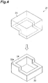
- FIG. 2 is a perspective view illustrating the relationship among the first member, the second member, and the bonding layer.
- FIG. 3 is a sectional view illustrating an insert-molded state in the injection molding process.
- the square metal container 12 which is open upward is prepared (see FIG. 2(a) ), and a large number of pores are formed on an upper end surface 12a of the metal container 12 through an alumite treatment, laser irradiation, or the like.
- a mold 16 which accommodates the metal container 12 and has a bonding layer formation space 15 for forming the bonding layer 14 on the upper end surface 12a of the metal container 12 is prepared.
- the metal container 12 is set in the mold 16 (see FIG 3(a) ), and the bonding layer material for forming the bonding layer is heated, melted, and poured into the bonding layer formation space 15 (see FIG. 3(b) ).
- the bonding layer 14 is laminated on the upper end surface 12a of the metal container 12. At this time, the melted bonding layer material infiltrates into the large number of pores formed in the upper end surface 12a of the metal container 12.
- the bonding layer material is cooled and solidified, the bonding strength of the bonding layer 14 to the upper end surface 12a is further increased by the anchoring effect. Accordingly, a bonding layer formed body in which the bonding layer 14 is injection-molded onto the upper end surface 12a can be formed (see FIG. 2(b) ).
- the resin cover 13 to be bonded to the metal container 12 is prepared (see FIG. 2(c) ), and the resin cover 13 is welded to the bonding layer 14 of the bonding layer formed body by laser welding. Accordingly, the bonded body 11 in which the metal container 12 and the resin cover 13 are firmly bonded to each other via the bonding layer 14 interposed therebetween can be formed (see FIG. 2(d) .
- the bonded body 1 since the number of air bubbles having a void area of 1.5 ⁇ 10 -3 ⁇ m 2 or greater in a range of 13 ⁇ m in the cross-section of the bonding interface between the first member 2 and the bonding layer 4 in the cross-section of the bonding layer 4 in the bonding direction ⁇ of the first member 2 and the second member 3 is 100 or less, the enhancement of the bonding strength of the first member 2 and the second member 3 can be achieved.
- the linear expansion relaxation effect of the bonding layer can be increased while increasing the bonding strength of the first member and the bonding layer.
- the linear expansion relaxation effect of the bonding layer can be increased while increasing the bonding strength of the first member and the bonding layer.
- the linear expansion relaxation effect of the bonding layer 4 can be further increased while further increasing the bonding strength of the first member 2 and the bonding layer 4.
- the bonding layer is integrally laminated on the bonding surface of the first member through the injection molding of the bonding layer, compared to a case where the first member and the bonding layer are bonded to each other by laser welding, the bonding layer more easily infiltrates into the gaps such as the pores formed in the surface of the first member, and the gaps are less likely to remain. As a result, the number of air bubbles generated in the bonding interface between the first member and the bonding layer can be reduced. Therefore, in the bonded body in which the first member and the second member are bonded to each other via the bonding layer interposed therebetween, the enhancement of the bonding strength of the first member and the second member can be achieved.
- the bonding layer is injection-molded onto the first member in the injection molding process (Step S1), even when the bonding surfaces of the first member and the second member have three-dimensional shapes, the bonding layer can be formed on the bonding surface of the first member, which is to be bonded to the second member. Accordingly, the first member and the second member can be appropriately bonded to each other in the bonding process (Step S2).
- a bonding layer 24 can be easily formed on a bonding surface 22a of the first member 22, and thus the first member 22 and the second member 23 can be appropriately bonded to each other.
- the injection-molded bonding layer does not deviate from the first member unlike the laser bonding sheet of Patent Literature 1 and thus achieves bonding quality stability.
- the bonding layer can be formed only in a necessary portion. Therefore, waste materials from the laser bonding sheet or processing costs are not generated unlike in Patent Literature 1, and thus a reduction in costs can be achieved.
- the bonding strength of the bonding layer to the first member is enhanced.
- the bonding layer infiltrates into the pores formed in the bonding surface in a state of being melted through injection molding, the bonding strength of the bonding layer to the first member is further enhanced.
- the bonding strength of the bonding layer to the second member is enhanced.
- Step S2 since the bonding layer infiltrates into the pores formed in the bonding surface in a state of being melted, the bonding strength of the bonding layer to the second member is further enhanced.
- the bonding layer is less likely to be bonded to metal than a resin.
- the bonding layer can be firmly bonded to the first member made of metal.
- the first member is formed of metal and the second member is formed of a resin.
- the first member and the second member are not limited to these materials, and may employ various materials.
- the first member may be formed of glass.
- the first member may be formed of a resin while the second member is formed of metal.
- the bonding layer may be formed on the first member through two-color molding or the like.
- the surface treatment process is performed before the injection molding process.
- a surface treatment process is not necessarily needed.
- a metal flat plate was used as a first member.
- aluminum (AL5052) and aluminum (ADC12) were used as the material of the first member.
- a polyamide resin composite material obtained by melting and kneading 80 mass% of PA 66 (trade name: Leona 1200, manufactured by Asahi Kasei Chemicals Corporation) and 20 mass% of an elastomer (trade name: Tuftec M1918, manufactured by Asahi Kasei Chemicals Corporation) using a twin screw extruder (trade name: TEM35, manufactured by Toshiba Machine Co., Ltd.) set to a barrel temperature of 290°C, diluting the obtained thermoplastic material 100 times with a Leona resin (trade name: 2300LA33295, manufactured by Asahi Kasei Chemicals Corporation), and mixing the resultant, and a polyamide resin composite material (hereinafter, referred to as "bonding material B”) obtained by melting and kneading 80 mass% of PA 66 (trade name: Leona 1200, manufactured by Asahi Kasei Chemicals Corporation).
- a cup-shaped container formed of a resin was used as a second member.
- the following materials were used. 3 mass% of potassium iodide and 0.1 mass% of copper iodide were added to an aqueous solution of a 40% AH salt (an equimolar salt of adipic acid, hexamethylenediamine, or the like) in a 400L autoclave, and the resultant was heated and melted under an increased pressure of 1.8 MPa so as to be polymerized.
- a 40% AH salt an equimolar salt of adipic acid, hexamethylenediamine, or the like
- thermoplastic material A a thermoplastic material
- thermoplastic material B 64.5 parts by mass of polyamide 66 obtained by allowing the obtained polymer to be subjected to cooling, solidification, and granulation, 33 parts by mass of glass fiber (trade name: T275H, manufactured by Asahi Kasei Chemicals Corporation), and 2.5 parts by mass of a color masterbatch for laser welding (trade name: eBIND ACW-9871, manufactured by Orient Chemical Industries Co., Ltd.) were melted and kneaded using a twin screw extruder (trade name: TEM35, manufactured by Toshiba Machine Co., Ltd.) set to a barrel temperature of 290°C, thereby obtaining a thermoplastic material (hereinafter, referred to as "resin material B").
- the resin material A and the resin material B obtained as described above were used as the material of the second member.
- pores were formed on a bonding surface of the first member, which was to be bonded to the second member, through an alumite treatment, the bonding layer was integrally laminated on the bonding surface of the first member through injection molding, and the second member and the bonding layer were laser-welded to each other, thereby producing a bonded body illustrated in FIG. 6 .
- An opening through which water was injected into the bonded body was formed in the first member.
- the alumite treatment is a treatment of forming an oxide film on the surface of metal at an appropriate current density and allowing the obtained film coated with the oxide to form pores.
- WD represents the distance from an optical system to the bonding surface of the first member.
- a destructive test was conducted on the bonded body.
- the bonded body was attached to the destructive test tool, water was injected through the inflow port of the destructive test tool, and a pressure at which breaking of the bonded body occurred or water leakage occurred was measured as a burst strength.
- a burst pressure of 1 MPa or higher was evaluated as ⁇
- a burst pressure of 0.1 MPa or higher and lower than 1 MPa was evaluated as ⁇
- 0 MPa which was measured because there were unwelded portions and leakage occurred although the portions were bonded in an external view
- non-welding was evaluated as ⁇ .
- the test results are shown in FIG. 8 .
- a metal flat plate was used as a first member.
- aluminum (AL5052) and aluminum (ADC12) were used as the material of the first member.
- a cup-shaped container formed of a resin was used as a bonding layer.
- the bonding material A and the bonding material B were used as the material of the bonding layer.
- a second member was formed of a resin.
- the resin material A and the resin material B were used.
- pores were formed on a bonding surface of the first member, which was to be bonded to the second member, through an alumite treatment, the bonding layer was placed on the bonding surface of the first member, and the first member, the second member, and the bonding layer were laser-welded to each other, thereby producing a bonded body illustrated in FIG. 6 .
- An opening through which water was injected into the bonded body was formed in the first member.
- the laser welding conditions were as shown in A to C fields of FIG. 7 .
- a destructive test was conducted on the bonded body.
- the bonded body was attached to a destructive test tool, water was injected through an inflow port of the destructive test tool, and a pressure at which breaking of the bonded body occurred or water leakage occurred was measured as a burst strength.
- a burst pressure of 1 MPa or higher was evaluated as ⁇
- a burst pressure of 0.1 MPa or higher and lower than 1 MPa was evaluated as ⁇
- 0 MPa which was measured because there were unwelded portions and leakage occurred although the portions were bonded in an external view, was evaluated as ⁇
- non-welding was evaluated as ⁇ .
- the test results are shown in FIG. 8 .
- a cup-shaped container formed of a resin was used as a first member.
- the resin material A was used as the material of the first member.
- a bonding layer was formed of a resin.
- the bonding material A was used as the material of the bonding layer.
- a metal flat plate was used as a second member.
- aluminum AL5052 was used as the material of the second member.
- first member and the bonding layer were integrally laminated by two-color molding, pores were formed on a bonding surface of the second member, which was to be bonded to the first member, through an alumite treatment, and the second member and the bonding layer were laser-welded to each other, thereby producing a bonded body illustrated in FIG. 9 .
- An opening through which water was injected into the bonded body was formed in the second member.
- the alumite treatment is a treatment of forming an oxide film on the surface of metal at an appropriate current density and allowing the obtained film coated with the oxide to form pores.
- the laser welding conditions were as shown in A to C fields of FIG. 7 .
- a destructive test was conducted on the bonded body.
- the bonded body was attached to the destructive test tool, water was injected through the inflow port of the destructive test tool, and a pressure at which breaking of the bonded body occurred or water leakage occurred was measured as a burst strength.
- a burst pressure of 1 MPa or higher was evaluated as ⁇
- a burst pressure of 0.1 MPa or higher and lower than 1 MPa was evaluated as ⁇
- 0 MPa which was measured because there were unwelded portions and leakage occurred although the portions were bonded in an external view
- non-welding was evaluated as ⁇ .
- the test results are shown in FIG. 10 .
- the first member and the second member were not peeled or separated from each other at an internal pressure of the burst test, and were not peeled or separated from each other as long as they were not forcibly pulled to be separated from each other.
- FIG 11 is a schematic view illustrating a method of counting the number of air bubbles.
- FIG. 12 is an enlarged view of a portion of FIG 11 . As illustrated in FIGS. 11 and 12 , from an SEM image (picture), a range of 13 ⁇ m in the cross-section of the bonding interface between the first member 2 and the bonding layer 4 was extracted, and the number of air bubbles having a void area of 1.5 ⁇ 10 -3 ⁇ m 2 or greater in the extracted range was counted.
- the number of air bubbles in the bonded body of Comparative Example 1 was 134, while the number of air bubbles in the bonded body of Example 1 was 31.
- the bonding strength of the first member and the second member was high.
- Reference Example 1 as a bonded body, a body in which a bonding member was integrally laminated onto a first member through injection molding was used. That is, in the bonded body of Reference Example 1, a second member was not provided, and the bonding member was used as a bonding layer.
- the first member As illustrated in FIG. 13 , as the first member, a long, thin, and flat plate formed of metal was used, and an end surface thereof, which was to be bonded to the bonding layer, was formed in a stepped shape having two steps.
- the stepped end surface had a step width of 10 mm and a step height of 3 mm.
- aluminum (AL5052) As the material of the first member, aluminum (AL5052) was used.
- the bonding material B having an elastic modulus of 1900 MPa was used.
- the bonding layer was integrally laminated onto the stepped end surface of the first member through injection molding, thereby obtaining a bonded body having a long, thin, and flat plate shape as the overall shape.
- Comparative Example 3 as a bonded body, a body in which a bonding member was integrally laminated onto a first member through injection molding was used. That is, in the bonded body of Comparative Example 3, a second member was not provided, and the bonding member was used as a bonding layer.
- the first member As illustrated in FIG. 13 , as the first member, a long, thin, and flat plate formed of metal was used, and an end surface thereof, which was to be bonded to the bonding layer, was formed in a stepped shape having two steps.
- the stepped end surface had a step width of 10 mm and a step height of 3 mm.
- aluminum (AL5052) As the material of the first member, aluminum (AL5052) was used.
- the resin material B having an elastic modulus of 9800 MPa was used.
- the bonding layer was integrally laminated onto the stepped end surface of the first member through injection molding, thereby obtaining a bonded body having a long, thin, and flat plate shape as the overall shape.
Abstract
Description
- The present invention relates to a bonded body in which a first member, and a second member formed of a material different from that of the first member are bonded to each other, and a bonding method thereof.
- Hitherto, as a method of bonding metal to a resin, there is a bonding method described in
Patent Literature 1. This bonding method is a manufacturing method of inserting a laser bonding sheet formed of a polymer between a first member formed of metal and a second member formed of a resin and melting the laser bonding sheet through laser light irradiation, thereby bonding the first member and the second member to each other. Accordingly, a bonded body in which the first member and the second member are bonded to each other with the laser bonding sheet interposed therebetween can be obtained. - Patent Literature 1: Japanese Patent No.
4771387 - However, when the first member formed of metal and the second member formed of a resin are welded to each other by laser welding, the material of the laser bonding sheet does not infiltrate into gaps such as pores formed on the surface of the first member formed of metal, and voids remain in the gaps. Therefore, there is a possibility that sufficient bonding strength of the first member and the second member may not be obtained.
- In addition, in the bonding method described in
Patent Literature 1, since the laser bonding sheet has a flat sheet shape, a case in which bonding surfaces of the first member and the second member have three-dimensional shapes cannot be coped with, and the degree of freedom of shape is extremely low. Furthermore, since the laser bonding sheet is simply interposed between the first member and the second member, the laser welding sheet has low position holding properties, and has a limitation on the enhancement of quality stability. Moreover, the laser bonding sheet needs to be manufactured to match the shape of the bonding surfaces of the first member and the second member. Therefore, a large amount of waste materials are generated during the manufacturing of the laser bonding sheet, and processing costs for the laser bonding sheet are required. - Here, an object of the present invention is to provide a bonded body capable of achieving the enhancement of bonding strength, and a bonding method.
- In a bonded body according to the present invention, a first member, and a second member formed of a material different from that of the first member are bonded to each other via a bonding layer interposed therebetween, and in a range of 13 µm in a cross-section of a bonding interface between the first member and the bonding layer, the number of air bubbles having a void area of 1.5×10⁻³ µm2 or greater is 100 or less.
- In the bonded body according to the present invention, since the number of air bubbles having a void area of 1.5×10⁻³ µm2 or greater in a range of 13 µm in the cross-section of the bonding interface between the
first member 2 and thebonding layer 4 is 100 or less, the enhancement of the bonding strength of the first member and the second member can be achieved. - In this case, the bonding layer may have a tensile elastic modulus of 800 MPa or higher and 2400 MPa or lower in an absolute dry state as a water absorption state at 23°C. Furthermore, the bonding layer may have a tensile elastic modulus of 1200 MPa or higher and 2000 MPa or lower in the absolute dry state as the water absorption state at 23°C. When the tensile elastic modulus of the bonding layer in the absolute dry state as the water absorption state at 23°C is lower than 800 MPa, the bonding strength of the first member and the bonding layer is low. When the tensile elastic modulus of the bonding layer in the absolute dry state as the water absorption state at 23°C is higher than 2400 MPa, the linear expansion relaxation effect of the bonding layer is decreased. Therefore, by allowing the tensile elastic modulus of the bonding layer at 23°C to be 800 MPa or higher and 2400 MPa or lower, the linear expansion relaxation effect of the bonding layer can be increased while increasing the bonding strength of the first member and the bonding layer.
- In addition, the bonding layer may contain an elastomer component in an amount of 5 wt% or more and 75 wt% or less. When the amount of the elastomer component is less than 5 wt%, the linear expansion relaxation effect of the bonding layer is decreased. When the amount of the elastomer component is more than 75 wt%, the bonding strength of the first member and the bonding layer is decreased. Therefore, by allowing the amount of the elastomer component of the bonding layer to be 5 wt% or more and 75 wt% or less, the linear expansion relaxation effect of the bonding layer can be increased while increasing the bonding strength of the first member and the bonding layer.
- In addition, the elastomer may have a tensile elastic modulus of 50 MPa or higher and 1000 MPa or lower in the absolute dry state as the water absorption state at 23°C. Accordingly, the linear expansion relaxation effect of the bonding layer can be further increased while further increasing the bonding strength of the first member and the bonding layer. In this case, examples of the elastomer may include a styrene-based elastomer, an olefin-based elastomer, an engineering plastic-based elastomer, and a polyester-based elastomer.
- A bonding method according to the present invention is a bonding method of bonding a first member to a second member which is formed of a material different from that of the first member, the method including: an injection molding process of integrally laminating a bonding layer for bonding the first member and the second member to each other, on a bonding surface of the first member, which is to be bonded to the second member, through injection molding; and a bonding process of bonding the second member to the bonding layer after the injection molding process.
- According to the bonding method according to the present invention, since the bonding layer is integrally laminated on the bonding surface of the first member through the injection molding of the bonding layer, compared to a case where the first member and the bonding layer are bonded to each other by laser welding, the bonding layer more easily infiltrates into gaps such as pores formed in the surface of the first member, and the gaps are less likely to remain. As a result, the number of air bubbles generated in the bonding interface between the first member and the bonding layer can be reduced. Therefore, in the bonded body in which the first member and the second member are bonded to each other via the bonding layer interposed therebetween, the enhancement of the bonding strength of the first member and the second member can be achieved. Furthermore, since the bonding layer is integrally laminated on the first member through injection molding in the injection molding process, even when the bonding surfaces of the first member and the second member have three-dimensional shapes, the bonding layer can be formed on the bonding surface of the first member, which is to be bonded to the second member. Accordingly, the first member and the second member can be appropriately bonded to each other in the bonding process. In addition, the injection-molded bonding layer does not deviate from the first member unlike the laser bonding sheet of
Patent Literature 1 and thus achieves bonding quality stability. Moreover, the bonding layer can be formed only in a necessary portion. Therefore, waste materials from the laser bonding sheet or processing costs are not generated unlike inPatent Literature 1, and thus a reduction in costs can be achieved. - In this case, in the bonding process, the second member may be bonded to the bonding layer through welding. Accordingly, the first member and the second member can be appropriately bonded to each other. Examples of the welding may include laser welding, hot plate welding, vibration welding, and ultrasonic welding, and among these, laser welding is preferable.
- In addition, the injection molding process may further include a surface treatment process of forming pores on the bonding surface of the first member. Accordingly, the bonding strength of the bonding layer to the first member is enhanced. Particularly, in the injection molding process, since the bonding layer infiltrates into the pores formed in the bonding surface in a state of being melted through injection molding, the bonding strength of the bonding layer to the first member is further enhanced.
- In addition, the first member may be formed of any one of metal and glass, and the second member may be formed of a resin. Accordingly, the resin can be appropriately bonded to the metal or the glass. Moreover, although the bonding layer is less likely to be bonded to the metal or the glass than the resin, the bonding layer can be firmly bonded to the metal or the glass by injection-molding the bonding layer onto the metal or the glass.
- According to the present invention, the enhancement of bonding strength can be achieved.
-
-
FIG. 1 is a flowchart illustrating a bonding method according to an embodiment. -
FIG. 2 is a perspective view illustrating the relationship among a first member, a second member, and a bonding layer. -
FIG. 3 is a sectional view illustrating an insert-molded state in an injection molding process. -
FIG. 4 is a perspective view illustrating a shape example of a bonding surface. -
FIG 5 is a schematic view illustrating a bonded body according to the embodiment. -
FIG. 6 is a sectional view illustrating a bonded body of Examples 1 to 11 and Comparative Examples 1 and 2. -
FIG. 7 is a view showing laser welding conditions. -
FIG. 8 is a view showing test results of Examples 1 to 11 and Comparative Examples 1 and 2. -
FIG. 9 is a sectional view illustrating a bonded body of Examples 12 to 14. -
FIG. 10 is a view showing test results of Examples 12 to 14. -
FIG. 11 is a schematic view illustrating a method of counting the number of air bubbles. -
FIG. 12 is an enlarged view of a portion ofFIG. 11 . -
FIG. 13 is a schematic view illustrating a method of conducting a heat shock test. -
FIG 14 is a view showing test results of Reference Example 1 and Comparative Example 3. - Hereinafter, a preferred exemplary embodiment of a bonded body and a bonding method according to the present invention will be described in detail with reference to the drawings. The bonded body according to the embodiment is a bonded body in which a first member, and a second member formed of a material different from that of the first member are bonded to each other via a bonding layer interposed therebetween. The bonding method according to the embodiment is a method which manufactures the bonded body according to the embodiment and in which a first member, and a second member formed of a material different from that of the first member are bonded by a bonding layer. In addition, in all of the figures, like elements that are the same or similar are denoted by like reference numerals.
-
FIG. 1 is a flowchart illustrating the bonding method according to the embodiment. As illustrated inFIG. 1 , in the bonding method according to the embodiment, first, an injection molding process (Step 1) of integrally laminating a bonding layer for bonding the first member and the second member to each other, on a bonding surface of the first member, which is to be bonded to the second member, through injection molding is performed. An injection molding method performed in the injection molding process (Step 1) is not particularly limited, and for example, in a case where the first member is formed of metal, glass, or ceramic, insert molding may be employed. In a case where the first member is formed of a resin, two-color molding may be employed. The injection molding method is not limited thereto, and various injection molding methods may be employed. Typically, the bonding surface of the first member, which is to be bonded to the second member, is not a completely flat surface, and has fine gaps formed therein. In a case where the first member is formed of metal, glass, or ceramic, it is preferable that pores be formed on the bonding surface of the first member which is to be bonded to the second member. The pores are formed to form the gaps in the bonding surface of the first member, which is to be bonded to the second member, and to further increase bonding strength of the first member (bonding surface) and the bonding layer. The formation of the pores may be performed through any treatment, and for example, may be performed through an alumite treatment or laser irradiation. In addition, a body formed by injection-molding the bonding layer onto the bonding surface in the injection molding process (Step S1) is referred to as a bonding layer formed body. - Next, a bonding process (Step S2) of bonding the second member to the bonding layer is performed. In addition, a body in which the second member is bonded to the bonding layer in the bonding process (Step S2) is referred to as a bonded body. The bonding method performed in the bonding process (Step S2) is not particularly limited, and for example, welding may be employed. Examples of the welding may include laser welding, hot plate welding, vibration welding, and ultrasonic welding, and among these, laser welding is preferable. In this case, for example, in a case where the second member is formed of metal, glass, or ceramic, the bonding layer can be formed on the second member by melting the bonding layer. In a case where the second member is formed of a resin, the second member may be bonded to the bonding layer by melting any of the bonding layer and the second member, or the second member may be bonded to the bonding layer by melting both of the bonding layer and the second member. Here, the bonding method is not limited to welding, and various bonding methods may be employed. In addition, in a case where the second member is formed of metal, glass, or ceramic, it is preferable that pores be formed on a bonding surface of the second member, which is to be bonded to the bonding layer. The pores are formed to increase the bonding strength of the second member (bonding surface) and the bonding layer. The formation of the pores may be performed through any treatment, and for example, may be performed through an alumite treatment or laser irradiation. A body in which the first member and the second member are bonded to each other via the bonding layer interposed therebetween in the bonding process (Step S2) is referred to as a bonded body.
-
FIG. 5 is a schematic view illustrating the bonded body according to the embodiment. As illustrated inFIG. 5 , a bondedbody 1 according to the embodiment is a bonded body in which afirst member 2, and asecond member 3 formed of a material different from that of thefirst member 2 are bonded to each other via abonding layer 4 interposed therebetween. Specifically, in the bondedbody 1, thebonding layer 4 is integrally laminated on a bonding surface 2a of thefirst member 2, which is to be bonded to thesecond member 3, through injection molding, and thesecond member 3 is bonded to thebonding layer 4. Thebonding layer 4 and thesecond member 3 are bonded to each other by welding. - In addition, in a range of 13 µm in the cross-section of the bonding interface between the
first member 2 and thebonding layer 4, the number or air bubbles having a void area of 1.5×10⁻³ µm2 or greater is 100 or less. In this case, the number of air bubbles is preferably 80 or less, more preferably 60 or less, and even more preferably 40 or less. - Here, a method of calculating the number of air bubbles will be described. First, broad ion beam processing is performed on the bonded
body 1 in each layer direction using IM4000 manufactured by Hitachi High-Technologies Corporation, thereby producing a cross-sectional sample in a bonding direction α of thefirst member 2 and thesecond member 3. In addition, the cross-sectional sample is observed by a scanning electron microscope (SEM). For example, observation conditions include S-4700 manufactured by Hitachi High-Technologies Corporation with an accelerating voltage of 2.0 kV and a photographic magnification of 10.0 k. Next, from an SEM image (picture), a range of 13 µm in the cross-section of the bonding interface between thefirst member 2 and thebonding layer 4 is extracted. Next, the number of air bubbles having a void area of 1.5×10⁻³ µm2 or greater in the extracted range is counted. In addition, the size of a void that can be recognized in the case of being magnified under conditions of an accelerating voltage of 2.0 kV and a photographic magnification of 10.0 k using the SEM is 1.5×10⁻³ µm2 or greater. In the bondedbody 1 according to the embodiment, the number of air bubbles that are bounded is 100 or less. The bondedbody 1 according to the embodiment can be manufactured, for example, by the above-described bonding method. - The material of the
first member 2 is not particularly limited, and various materials such as metal, glass, ceramic, and resins may be used. For example, in a case where thebonding layer 4 and thesecond member 3 are laser-welded to each other by emitting laser light from thefirst member 2 side in the bonding process (Step S2), a material having a property of transmitting the laser light is preferably used for thefirst member 2. - The material of the
second member 3 is not particularly limited as long as the material is different from that of thefirst member 2, and various materials such as metal, glass, ceramic, and resins may be used. For example, in a case where thebonding layer 4 and thesecond member 3 are laser-welded to each other by emitting laser light from thesecond member 3 side in the bonding process (Step S2), a material having a property of transmitting the laser light is preferably used for thesecond member 3. - The material (also referred to as "bonding layer material") of the
bonding layer 4 is not particularly limited as long as the material can bond the first member and the second member to each other, and various bonding materials may be used. For example, in a case where thebonding layer 4 and thesecond member 3 are laser-welded to each other in the bonding process (Step S2), a material that is melted by laser irradiation is preferably used for thebonding layer 4. - For example, the
bonding layer 4 may contain an elastomer component in an amount of 5 wt% or more and 75 wt% or less. In this case, the elastomer component is preferably in an amount of 10 wt% or more and 70 wt% or less, more preferably in an amount of 15 wt% or more and 65 wt% or less, and even more preferably in an amount of 20 wt% or more and 60 wt% or less. When the amount of the elastomer component is more than 75 wt% (when the rubber content is too high), the fluidity is decreased, and the elastomer component is less likely to infiltrate into the pores (gaps) of thefirst member 2, resulting in a decrease in the bonding strength of the first member and the bonding layer. Therefore, by allowing the amount of the elastomer component of the bonding layer to be 75 wt% or less, the fluidity is increased, and the elastomer component easily infiltrates into the pores (gaps) of thefirst member 2. Accordingly, the bonding strength of the first member and the bonding layer can be increased. On the other hand, when the amount of the elastomer component is less than 5 wt% (when the rubber content is too low), the linear expansion relaxation effect of the bonding layer is decreased. Therefore, by allowing the amount of the elastomer component of the bonding layer to be 5 wt% or more, the linear expansion relaxation effect of the bonding layer can be increased. - The elastomer contained in the
bonding layer 4 may be, for example, an elastomer having a tensile elastic modulus of 50 MPa or higher and 1000 MPa or lower in an absolute dry state as a water absorption state at 23°C. Here, the absolute dry state as the water absorption state means a state in which the moisture content is 0.1% or less. Accordingly, the linear expansion relaxation effect of the bonding layer can be further increased while further increasing the bonding strength of the first member and the bonding layer. In this case, examples of the elastomer contained in thebonding layer 4 include a styrene-based elastomer, an olefin-based elastomer, an engineering plastic-based elastomer, and a polyester-based elastomer. - In addition, from the viewpoint of maintaining high bonding strength, the tensile elastic modulus of the
bonding layer 4 in the absolute dry state as the water absorption state at 23°C may be 800 MPa or higher and 2400 MPa or lower. In this case, the tensile elastic modulus of thebonding layer 4 in the absolute dry state as the water absorption state at 23°C is preferably 1200 MPa or higher and 2000 MPa or lower, and more preferably 1600 MPa or higher and 1900 MPa or lower. When the tensile elastic modulus of thebonding layer 4 in the absolute dry state as the water absorption state at 23°C is lower than 800 MPa, the bonding strength of the first member and the bonding layer is low. When the tensile elastic modulus of the bonding layer in the absolute dry state as the water absorption state at 23°C is higher than 2400 MPa, the linear expansion relaxation effect of the bonding layer is decreased. - Next, as a specific example of the bonded body and the bonding method according to the embodiment, the case of manufacturing a bonded
body 11 in which asquare metal container 12 and aresin cover 13 are bonded to each other via abonding layer 14 interposed therebetween will be described with reference toFIGS. 2 and3 . -
FIG. 2 is a perspective view illustrating the relationship among the first member, the second member, and the bonding layer.FIG. 3 is a sectional view illustrating an insert-molded state in the injection molding process. - First, the
square metal container 12 which is open upward is prepared (seeFIG. 2(a) ), and a large number of pores are formed on anupper end surface 12a of themetal container 12 through an alumite treatment, laser irradiation, or the like. - Next, as illustrated in
FIG. 3 , amold 16 which accommodates themetal container 12 and has a bondinglayer formation space 15 for forming thebonding layer 14 on theupper end surface 12a of themetal container 12 is prepared. In addition, themetal container 12 is set in the mold 16 (seeFIG 3(a) ), and the bonding layer material for forming the bonding layer is heated, melted, and poured into the bonding layer formation space 15 (seeFIG. 3(b) ). In addition, by allowing the bonding layer material to be cooled and solidified, thebonding layer 14 is laminated on theupper end surface 12a of themetal container 12. At this time, the melted bonding layer material infiltrates into the large number of pores formed in theupper end surface 12a of themetal container 12. Therefore, as the bonding layer material is cooled and solidified, the bonding strength of thebonding layer 14 to theupper end surface 12a is further increased by the anchoring effect. Accordingly, a bonding layer formed body in which thebonding layer 14 is injection-molded onto theupper end surface 12a can be formed (seeFIG. 2(b) ). - Next, the
resin cover 13 to be bonded to themetal container 12 is prepared (seeFIG. 2(c) ), and theresin cover 13 is welded to thebonding layer 14 of the bonding layer formed body by laser welding. Accordingly, the bondedbody 11 in which themetal container 12 and theresin cover 13 are firmly bonded to each other via thebonding layer 14 interposed therebetween can be formed (seeFIG. 2(d) . - As described above, according to the bonded
body 1 according to the embodiment, since the number of air bubbles having a void area of 1.5×10⁻³ µm2 or greater in a range of 13 µm in the cross-section of the bonding interface between thefirst member 2 and thebonding layer 4 in the cross-section of thebonding layer 4 in the bonding direction α of thefirst member 2 and thesecond member 3 is 100 or less, the enhancement of the bonding strength of thefirst member 2 and thesecond member 3 can be achieved. - In addition, by allowing the tensile elastic modulus of the
bonding layer 4 in the absolute dry state as the water absorption state at 23°C to be 800 MPa or higher and 2400 MPa or lower, the linear expansion relaxation effect of the bonding layer can be increased while increasing the bonding strength of the first member and the bonding layer. - In addition, by allowing the amount of the elastomer component in the bonding layer to be 5 wt% or more and 75 wt% or less, the linear expansion relaxation effect of the bonding layer can be increased while increasing the bonding strength of the first member and the bonding layer.
- In addition, by allowing the tensile elastic modulus of the elastomer in the absolute dry state as the water absorption state at 23 °C to be 50 MPa or higher and 1000 MPa or lower, the linear expansion relaxation effect of the
bonding layer 4 can be further increased while further increasing the bonding strength of thefirst member 2 and thebonding layer 4. - According to the bonding method according to the embodiment, since the bonding layer is integrally laminated on the bonding surface of the first member through the injection molding of the bonding layer, compared to a case where the first member and the bonding layer are bonded to each other by laser welding, the bonding layer more easily infiltrates into the gaps such as the pores formed in the surface of the first member, and the gaps are less likely to remain. As a result, the number of air bubbles generated in the bonding interface between the first member and the bonding layer can be reduced. Therefore, in the bonded body in which the first member and the second member are bonded to each other via the bonding layer interposed therebetween, the enhancement of the bonding strength of the first member and the second member can be achieved. Furthermore, since the bonding layer is injection-molded onto the first member in the injection molding process (Step S1), even when the bonding surfaces of the first member and the second member have three-dimensional shapes, the bonding layer can be formed on the bonding surface of the first member, which is to be bonded to the second member. Accordingly, the first member and the second member can be appropriately bonded to each other in the bonding process (Step S2). For example, as in a bonded
body 21 illustrated inFIG. 4 , even when bonding surfaces of afirst member 22 and thesecond member 23 are formed in a three-dimensional stepped shape, abonding layer 24 can be easily formed on abonding surface 22a of thefirst member 22, and thus thefirst member 22 and thesecond member 23 can be appropriately bonded to each other. - In addition, the injection-molded bonding layer does not deviate from the first member unlike the laser bonding sheet of
Patent Literature 1 and thus achieves bonding quality stability. Moreover, the bonding layer can be formed only in a necessary portion. Therefore, waste materials from the laser bonding sheet or processing costs are not generated unlike inPatent Literature 1, and thus a reduction in costs can be achieved. - In addition, in a case where the first member is formed of metal, glass, or ceramic, by forming the pores in the first member, the bonding strength of the bonding layer to the first member is enhanced. In the injection molding process (Step S1), since the bonding layer infiltrates into the pores formed in the bonding surface in a state of being melted through injection molding, the bonding strength of the bonding layer to the first member is further enhanced. Similarly, in a case where the second member is formed of metal, glass, or ceramic, by forming the pores in the second member, the bonding strength of the bonding layer to the second member is enhanced. In the case of melting the bonding layer in the bonding process (Step S2), since the bonding layer infiltrates into the pores formed in the bonding surface in a state of being melted, the bonding strength of the bonding layer to the second member is further enhanced.
- In addition, the bonding layer is less likely to be bonded to metal than a resin. However, by injection-molding the bonding layer onto the first member made of metal, the bonding layer can be firmly bonded to the first member made of metal.
- While the exemplary embodiment of the present invention has been described above, the present invention is not limited to the embodiment.
- For example, in the detailed description of the embodiment, the first member is formed of metal and the second member is formed of a resin. However, the first member and the second member are not limited to these materials, and may employ various materials. For example, the first member may be formed of glass. Otherwise, the first member may be formed of a resin while the second member is formed of metal. In the case of forming the first member of the resin, the bonding layer may be formed on the first member through two-color molding or the like.
- In addition, in the description of the embodiment, the surface treatment process is performed before the injection molding process. However, when the connection strength of the bonding layer to the bonding surface of the first member causes no problem, such a surface treatment process is not necessarily needed.
- Next, Examples of the present invention will be described. The present invention is not limited to the following Examples.
- As a first member, a metal flat plate was used. As the material of the first member, aluminum (AL5052) and aluminum (ADC12) were used.
- As the material of a bonding layer, the following materials were used. A polyamide resin composite material (hereinafter, referred to as "bonding material A") obtained by melting and kneading 80 mass% of PA 66 (trade name: Leona 1200, manufactured by Asahi Kasei Chemicals Corporation) and 20 mass% of an elastomer (trade name: Tuftec M1918, manufactured by Asahi Kasei Chemicals Corporation) using a twin screw extruder (trade name: TEM35, manufactured by Toshiba Machine Co., Ltd.) set to a barrel temperature of 290°C, diluting the obtained
thermoplastic material 100 times with a Leona resin (trade name: 2300LA33295, manufactured by Asahi Kasei Chemicals Corporation), and mixing the resultant, and a polyamide resin composite material (hereinafter, referred to as "bonding material B") obtained by melting and kneading 80 mass% of PA 66 (trade name: Leona 1200, manufactured by Asahi Kasei Chemicals Corporation) and 20 mass% of an elastomer (trade name: Tuftec M1918, manufactured by Asahi Kasei Chemicals Corporation) using a twin screw extruder (trade name: TEM35, manufactured by Toshiba Machine Co., Ltd.) set to a barrel temperature of 290°C, were used. - As a second member, a cup-shaped container formed of a resin was used. As the material of the second member, the following materials were used. 3 mass% of potassium iodide and 0.1 mass% of copper iodide were added to an aqueous solution of a 40% AH salt (an equimolar salt of adipic acid, hexamethylenediamine, or the like) in a 400L autoclave, and the resultant was heated and melted under an increased pressure of 1.8 MPa so as to be polymerized. 67 parts by mass of polyamide 66 obtained by allowing the obtained polymer to be subjected to cooling, solidification, and granulation, and 33 parts by mass of glass fiber (trade name: T275H, manufactured by Asahi Kasei Chemicals Corporation) were melted and kneaded using a twin screw extruder (trade name: TEM35, manufactured by Toshiba Machine Co., Ltd.) set to a barrel temperature of 290°C, thereby obtaining a thermoplastic material (hereinafter, referred to as "resin material A"). 3 mass% of potassium iodide and 0.1 mass% of copper iodide were added to an aqueous solution of a 40% AH salt (an equimolar salt of adipic acid, hexamethylenediamine, or the like) in a 400L autoclave, and the resultant was heated and melted under an increased pressure of 1.8 MPa so as to be polymerized. 64.5 parts by mass of polyamide 66 obtained by allowing the obtained polymer to be subjected to cooling, solidification, and granulation, 33 parts by mass of glass fiber (trade name: T275H, manufactured by Asahi Kasei Chemicals Corporation), and 2.5 parts by mass of a color masterbatch for laser welding (trade name: eBIND ACW-9871, manufactured by Orient Chemical Industries Co., Ltd.) were melted and kneaded using a twin screw extruder (trade name: TEM35, manufactured by Toshiba Machine Co., Ltd.) set to a barrel temperature of 290°C, thereby obtaining a thermoplastic material (hereinafter, referred to as "resin material B"). The resin material A and the resin material B obtained as described above were used as the material of the second member.
- In addition, pores were formed on a bonding surface of the first member, which was to be bonded to the second member, through an alumite treatment, the bonding layer was integrally laminated on the bonding surface of the first member through injection molding, and the second member and the bonding layer were laser-welded to each other, thereby producing a bonded body illustrated in
FIG. 6 . An opening through which water was injected into the bonded body was formed in the first member. - The alumite treatment is a treatment of forming an oxide film on the surface of metal at an appropriate current density and allowing the obtained film coated with the oxide to form pores.
- The laser welding conditions were as shown in A to C fields of
FIG. 7 . InFIG. 7 , WD represents the distance from an optical system to the bonding surface of the first member. - A destructive test was conducted on the bonded body. In destructive inspection, the bonded body was attached to the destructive test tool, water was injected through the inflow port of the destructive test tool, and a pressure at which breaking of the bonded body occurred or water leakage occurred was measured as a burst strength. As a result of the test, a burst pressure of 1 MPa or higher was evaluated as ⊙, a burst pressure of 0.1 MPa or higher and lower than 1 MPa was evaluated as ○, 0 MPa, which was measured because there were unwelded portions and leakage occurred although the portions were bonded in an external view, was evaluated as Δ, and non-welding was evaluated as ×. The test results are shown in
FIG. 8 . - As a first member, a metal flat plate was used. As the material of the first member, aluminum (AL5052) and aluminum (ADC12) were used.
- As a bonding layer, a cup-shaped container formed of a resin was used. As the material of the bonding layer, the bonding material A and the bonding material B were used.
- A second member was formed of a resin. As the material of the second member, the resin material A and the resin material B were used.
- In addition, pores were formed on a bonding surface of the first member, which was to be bonded to the second member, through an alumite treatment, the bonding layer was placed on the bonding surface of the first member, and the first member, the second member, and the bonding layer were laser-welded to each other, thereby producing a bonded body illustrated in
FIG. 6 . An opening through which water was injected into the bonded body was formed in the first member. - The laser welding conditions were as shown in A to C fields of
FIG. 7 . - A destructive test was conducted on the bonded body. In destructive inspection, the bonded body was attached to a destructive test tool, water was injected through an inflow port of the destructive test tool, and a pressure at which breaking of the bonded body occurred or water leakage occurred was measured as a burst strength. As a result of the test, a burst pressure of 1 MPa or higher was evaluated as ⊙, a burst pressure of 0.1 MPa or higher and lower than 1 MPa was evaluated as ○, 0 MPa, which was measured because there were unwelded portions and leakage occurred although the portions were bonded in an external view, was evaluated as Δ, and non-welding was evaluated as ×. The test results are shown in
FIG. 8 . - As shown in
FIG. 8 , in both of Comparative Examples 1 and 2, the first member and the second member were peeled and separated from each other before a burst test. However, in Examples 1 to 11, the first member and the second member were not peeled or separated from each other at an internal pressure of the burst test, and were not peeled or separated from each other as long as they were not forcibly pulled to be separated from each other. - As a first member, a cup-shaped container formed of a resin was used. As the material of the first member, the resin material A was used.
- A bonding layer was formed of a resin. As the material of the bonding layer, the bonding material A was used.
- As a second member, a metal flat plate was used. As the material of the second member, aluminum (AL5052) was used.
- In addition, the first member and the bonding layer were integrally laminated by two-color molding, pores were formed on a bonding surface of the second member, which was to be bonded to the first member, through an alumite treatment, and the second member and the bonding layer were laser-welded to each other, thereby producing a bonded body illustrated in
FIG. 9 . An opening through which water was injected into the bonded body was formed in the second member. - The alumite treatment is a treatment of forming an oxide film on the surface of metal at an appropriate current density and allowing the obtained film coated with the oxide to form pores.
- The laser welding conditions were as shown in A to C fields of
FIG. 7 . - A destructive test was conducted on the bonded body. In destructive inspection, the bonded body was attached to the destructive test tool, water was injected through the inflow port of the destructive test tool, and a pressure at which breaking of the bonded body occurred or water leakage occurred was measured as a burst strength. As a result of the test, a burst pressure of 1 MPa or higher was evaluated as ⊙, a burst pressure of 0.1 MPa or higher and lower than 1 MPa was evaluated as ○, 0 MPa, which was measured because there were unwelded portions and leakage occurred although the portions were bonded in an external view, was evaluated as Δ, and non-welding was evaluated as ×. The test results are shown in
FIG. 10 . - As illustrated in
FIG. 10 , in all of Examples 12 to 14, the first member and the second member were not peeled or separated from each other at an internal pressure of the burst test, and were not peeled or separated from each other as long as they were not forcibly pulled to be separated from each other. - The bonded body of Example 1 and the bonded body of Comparative Example 1 were prepared. Each of the bonded bodies was cut in the bonding direction of the first member and the second member, and the cut surface was observed through SEM.
FIG 11 is a schematic view illustrating a method of counting the number of air bubbles.FIG. 12 is an enlarged view of a portion ofFIG 11 . As illustrated inFIGS. 11 and12 , from an SEM image (picture), a range of 13 µm in the cross-section of the bonding interface between thefirst member 2 and thebonding layer 4 was extracted, and the number of air bubbles having a void area of 1.5×10⁻³ µm2 or greater in the extracted range was counted. - As a result, the number of air bubbles in the bonded body of Comparative Example 1 was 134, while the number of air bubbles in the bonded body of Example 1 was 31. As described above, it was presumed that since the number of air bubbles in the bonding layer in the bonded body of Example 1 was significantly reduced compared to that in the bonded body of Comparative Example 1, the bonding strength of the first member and the second member was high.
- In Reference Example 1, as a bonded body, a body in which a bonding member was integrally laminated onto a first member through injection molding was used. That is, in the bonded body of Reference Example 1, a second member was not provided, and the bonding member was used as a bonding layer.
- As illustrated in
FIG. 13 , as the first member, a long, thin, and flat plate formed of metal was used, and an end surface thereof, which was to be bonded to the bonding layer, was formed in a stepped shape having two steps. The stepped end surface had a step width of 10 mm and a step height of 3 mm. As the material of the first member, aluminum (AL5052) was used. As the material of the bonding layer, the bonding material B having an elastic modulus of 1900 MPa was used. In addition, the bonding layer was integrally laminated onto the stepped end surface of the first member through injection molding, thereby obtaining a bonded body having a long, thin, and flat plate shape as the overall shape. - Thereafter, a heat shock test was conducted. In the heat shock test, first, the bonded body of Reference Example 1 was fixed to metal (SUS) having low linear expansion in order to forcibly hold the linear expansion of the first member and the connection member. Next, assuming -35±5°C × 2 hours and 130±5°C × 2 hours as 1 cycle, 50 cycles, 100 cycles, and 150 cycles were conducted, and the tensile strength retention ratio at this time was measured. The tensile strength retention ratio was expressed as a percentage when the tensile strength retention ratio at 0 cycle (a state before the experiment) is set to 100%, The test results are shown in
FIG. 14 . - In Comparative Example 3, as a bonded body, a body in which a bonding member was integrally laminated onto a first member through injection molding was used. That is, in the bonded body of Comparative Example 3, a second member was not provided, and the bonding member was used as a bonding layer.
- As illustrated in
FIG. 13 , as the first member, a long, thin, and flat plate formed of metal was used, and an end surface thereof, which was to be bonded to the bonding layer, was formed in a stepped shape having two steps. The stepped end surface had a step width of 10 mm and a step height of 3 mm. As the material of the first member, aluminum (AL5052) was used. As the material of the bonding layer, the resin material B having an elastic modulus of 9800 MPa was used. In addition, the bonding layer was integrally laminated onto the stepped end surface of the first member through injection molding, thereby obtaining a bonded body having a long, thin, and flat plate shape as the overall shape. - Thereafter, a heat shock test was conducted. In the heat shock test, first, the bonded body of Comparative Example 3 was fixed to metal (SUS) having low linear expansion in order to forcibly hold the linear expansion of the first member and the connection member. Next, assuming -35±5°C × 2 hours and 130±5°C × 2 hours as 1 cycle, 50 cycles, 100 cycles, and 150 cycles were conducted, and the tensile strength retention ratio at this time was measured. The tensile strength retention ratio was expressed as a percentage when the tensile strength retention ratio at 0 cycle (a state before the experiment) is set to 100%. The test results are shown in
FIG. 14 . - As illustrated in
FIG. 14 , in Comparative Example 3, after 50 cycles had passed, the tensile strength retention ratio was already 0%, that is, the first member and the connection member were in a broken state. However, in Reference Example 1, even when 150 cycles had passed, the tensile strength retention ratio was 4.3, that is, the first member and the connection member were in a state of not being broken. From the results, in the present invention, it was found that by using the bonding member having a low elastic modulus as the bonding layer, the tensile strength retention ratio between the first member and the bonding layer could be maintained even under harsh temperature cycle conditions. -
- 1
- bonded body
- 2
- first member
- 2a
- bonding surface
- 3
- second member
- 4
- bonding layer
- 11
- bonded body
- 12
- metal container (first member)
- 12a
- upper end surface
- 13
- resin cover (second member)
- 14
- bonding layer
- 15
- bonding layer formation space
- 16
- mold
- 21
- bonded body
- 22
- first member
- 22a
- bonding surface
- 23
- second member
- 24
- bonding layer
- α
- bonding direction
Claims (9)
- A bonded body, wherein
a first member, and a second member formed of a material different from that of the first member are bonded to each other via a bonding layer interposed therebetween, and
in a range of 13 µm in a cross-section of a bonding interface between the first member and the bonding layer, the number of air bubbles having a void area of 1.5×10⁻³ µm2 or greater is 100 or less. - The bonded body according to claim 1,
wherein the bonding layer has a tensile elastic modulus of 800 MPa or higher and 2400 MPa or lower in an absolute dry state as a water absorption state at 23°C. - The bonded body according to claim 2,
wherein the bonding layer has a tensile elastic modulus of 1200 MPa or higher and 2000 MPa or lower in the absolute dry state as the water absorption state at 23°C. - The bonded body according to any one of claims 1 to 3,
wherein the bonding layer contains an elastomer component in an amount of 5 wt% or more and 75 wt% or less. - The bonded body according to claim 4,
wherein the elastomer has a tensile elastic modulus of 50 MPa or higher and 1000 MPa or lower in the absolute dry state as the water absorption state at 23°C. - A bonding method of bonding a first member to a second member which is formed of a material different from that of the first member, the method comprising:an injection molding process of integrally laminating a bonding layer for bonding the first member and the second member to each other, on a bonding surface of the first member, which is to be bonded to the second member, through injection molding; anda bonding process of bonding the second member to the bonding layer after the injection molding process.
- The bonding method according to claim 6,
wherein, in the bonding process, the second member is bonded to the bonding layer through welding. - The bonding method according to claim 6 or 7,
wherein the injection molding process further includes a surface treatment process of forming pores on the bonding surface of the first member. - The bonding method according to any one of claims 6 to 8,
wherein the first member is formed of any one of metal and glass, and
the second member is formed of a resin.
Applications Claiming Priority (2)
| Application Number | Priority Date | Filing Date | Title |
|---|---|---|---|
| JP2013168824 | 2013-08-15 | ||
| PCT/JP2014/071186 WO2015022933A1 (en) | 2013-08-15 | 2014-08-11 | Bonded body and bonding method |
Publications (3)
| Publication Number | Publication Date |
|---|---|
| EP3034277A1 true EP3034277A1 (en) | 2016-06-22 |
| EP3034277A4 EP3034277A4 (en) | 2016-08-24 |
| EP3034277B1 EP3034277B1 (en) | 2018-02-28 |
Family
ID=52468319
Family Applications (1)
| Application Number | Title | Priority Date | Filing Date |
|---|---|---|---|
| EP14836080.3A Active EP3034277B1 (en) | 2013-08-15 | 2014-08-11 | Bonded body and bonding method |
Country Status (6)
| Country | Link |
|---|---|
| US (1) | US20160221254A1 (en) |
| EP (1) | EP3034277B1 (en) |
| JP (1) | JP6181186B2 (en) |
| CN (1) | CN105473311B (en) |
| ES (1) | ES2664077T3 (en) |
| WO (1) | WO2015022933A1 (en) |
Families Citing this family (5)
| Publication number | Priority date | Publication date | Assignee | Title |
|---|---|---|---|---|
| US10502250B2 (en) | 2016-01-19 | 2019-12-10 | The Boeing Company | Methods and systems for slot joining using slot cases |
| JP6441295B2 (en) * | 2016-12-26 | 2018-12-19 | 本田技研工業株式会社 | Junction structure and manufacturing method thereof |
| CN111194259B (en) * | 2017-09-29 | 2022-01-14 | 本田技研工业株式会社 | Resin bonded body and method for producing same |
| DE102019201350A1 (en) | 2019-02-01 | 2020-08-06 | Lpkf Laser & Electronics Ag | Process for producing a glass-plastic connection |
| DE102020209825A1 (en) | 2020-08-04 | 2022-02-10 | Lpkf Laser & Electronics Aktiengesellschaft | Production of plastic parts with glass inserts |
Family Cites Families (20)
| Publication number | Priority date | Publication date | Assignee | Title |
|---|---|---|---|---|
| JP2007036130A (en) * | 2005-07-29 | 2007-02-08 | Canon Inc | Substrate joining method and apparatus thereof utilizing difference in thermal expansion coefficient |
| DE102005056460A1 (en) * | 2005-11-26 | 2007-06-06 | Daimlerchrysler Ag | Assembling a component with metal and plastic parts, e.g. for vehicle chassis items, involves covering the joint region with a melt adhesive coating |
| US20100009150A1 (en) * | 2006-10-05 | 2010-01-14 | Okayama Prefectural Government | Intermediate member for laser bonding and method of bonding using the same |
| DE102007009928A1 (en) * | 2007-01-24 | 2008-07-31 | Hühoco Metalloberflächenveredelung Gmbh | Process for producing a plastic and metal hybrid component and metal-plastic composite body |
| JP5194629B2 (en) * | 2007-08-10 | 2013-05-08 | 東洋紡株式会社 | Joining method of thermoplastic resin material and metal material |
| JP4678021B2 (en) * | 2007-11-06 | 2011-04-27 | 株式会社デンソー | Laser welding method of resin material |
| EP2226185B1 (en) * | 2007-11-29 | 2017-04-26 | Ngk Spark Plug Co., Ltd. | Metal-resin compound member |
| JP4771387B2 (en) * | 2008-04-09 | 2011-09-14 | 岡山県 | Joining method using laser light |
| JP4626687B2 (en) * | 2008-08-19 | 2011-02-09 | トヨタ自動車株式会社 | Bonding method between resin and metal |
| JP5396788B2 (en) * | 2008-09-17 | 2014-01-22 | 宇部興産株式会社 | Composite structure and manufacturing method thereof |
| JP2010144086A (en) * | 2008-12-19 | 2010-07-01 | Kyocera Chemical Corp | Die-bonding paste and semiconductor device using same |
| JP4849574B2 (en) * | 2009-02-26 | 2012-01-11 | 岡山県 | Joining method using laser light |
| JP5108904B2 (en) * | 2010-02-01 | 2012-12-26 | 大成プラス株式会社 | Composite of metal and polyamide resin composition and method for producing the same |
| JP5899634B2 (en) * | 2010-03-16 | 2016-04-06 | 宇部興産株式会社 | Composite structure |
| TWI404615B (en) * | 2010-04-01 | 2013-08-11 | A method of manufacturing an in-mold formed film having a metal surface | |
| CN102441962B (en) * | 2010-10-09 | 2014-04-09 | 广达电脑股份有限公司 | Method for manufacturing electronic device shell |
| EP2468472A1 (en) * | 2010-12-23 | 2012-06-27 | ABB Research Ltd. | A component made from the materials of two thermoplastics and the method of its production |
| TW201313454A (en) * | 2011-09-27 | 2013-04-01 | Ichia Tech Inc | Method for bonding plastic mold member onto metal housing |
| JP6022782B2 (en) * | 2012-03-19 | 2016-11-09 | ファスフォードテクノロジ株式会社 | Die bonder |
| JP2013244614A (en) * | 2012-05-23 | 2013-12-09 | Denso Corp | Composite resin molded product and method of producing the same |
-
2014
- 2014-08-11 EP EP14836080.3A patent/EP3034277B1/en active Active
- 2014-08-11 US US14/908,338 patent/US20160221254A1/en not_active Abandoned
- 2014-08-11 WO PCT/JP2014/071186 patent/WO2015022933A1/en active Application Filing
- 2014-08-11 ES ES14836080.3T patent/ES2664077T3/en active Active
- 2014-08-11 JP JP2015531809A patent/JP6181186B2/en active Active
- 2014-08-11 CN CN201480043203.7A patent/CN105473311B/en active Active
Also Published As
| Publication number | Publication date |
|---|---|
| EP3034277A4 (en) | 2016-08-24 |
| ES2664077T3 (en) | 2018-04-18 |
| CN105473311B (en) | 2018-02-09 |
| ES2664077T8 (en) | 2018-05-07 |
| JP6181186B2 (en) | 2017-08-16 |
| CN105473311A (en) | 2016-04-06 |
| EP3034277B1 (en) | 2018-02-28 |
| WO2015022933A1 (en) | 2015-02-19 |
| JPWO2015022933A1 (en) | 2017-03-02 |
| US20160221254A1 (en) | 2016-08-04 |
Similar Documents
| Publication | Publication Date | Title |
|---|---|---|
| EP3034277B1 (en) | Bonded body and bonding method | |
| EP3498416B1 (en) | Bonded structure of heterogeneous materials and method for manufacturing same | |
| KR101512888B1 (en) | Method of laser joining of aluminum alloy member and resin member | |
| JP6094779B2 (en) | Metal resin composite material, method for producing the same, and aluminum substrate having an aluminum oxide coating | |
| US20150218710A1 (en) | Composite and method for making the same | |
| KR101651387B1 (en) | Method for manufacturing composite hollow container, and composite hollow container | |
| TWI510367B (en) | Composite of metal and resin and method of manufacturing thereof | |
| WO2007066477A1 (en) | Method for manufacture of housing part provided with ventilation filter, and method for manufacture of housing provided with ventilation filter | |
| KR20110043530A (en) | Integrally injection-molded aluminum/resin article and process for producing the same | |
| KR101499665B1 (en) | Method for manufacturing composite molded article | |
| US20170015047A1 (en) | Composite molded article and method for manufacturing same | |
| JP5673814B2 (en) | Aluminum shape body for manufacturing aluminum / resin injection integrated molded article, aluminum / resin injection integrated molded article using the same, and manufacturing method thereof | |
| WO2018105437A1 (en) | Poly(arylene sulfide) resin composition and insert-molded article | |
| JP7020874B2 (en) | Composite member and its manufacturing method | |
| JP5744361B1 (en) | Manufacturing method of composite molded product | |
| JP2011240685A (en) | Seal structure for metallic composite joint body and method of manufacturing the same | |
| WO2013137046A1 (en) | Metal insert-molded article having sealability, electronic component having sealability and provided with said metal insert-molded article, and method for producing metal insert-molded article having sealability | |
| JP4704868B2 (en) | Chassis frame manufacturing method and chassis frame for large flat display device | |
| JP6814768B2 (en) | Liquid-proof connector | |
| US20230341195A1 (en) | Heat exchange device and method for manufacturing heat exchange device | |
| JP7010255B2 (en) | Metal resin joint member and its manufacturing method | |
| KR101396196B1 (en) | Magnecium alloy-resin composite and method of producing the same and method of producing magnecium alloy | |
| JP2004351246A (en) | Method for producing hollow fiber membrane module | |
| JP2022187795A (en) | Method for manufacturing composite member of plated metal and resin, and composite member | |
| JP2010274456A (en) | Resin-metal complex and method for manufacturing the same |
Legal Events
| Date | Code | Title | Description |
|---|---|---|---|
| PUAI | Public reference made under article 153(3) epc to a published international application that has entered the european phase |
Free format text: ORIGINAL CODE: 0009012 |
|
| 17P | Request for examination filed |
Effective date: 20160127 |
|
| AK | Designated contracting states |
Kind code of ref document: A1 Designated state(s): AL AT BE BG CH CY CZ DE DK EE ES FI FR GB GR HR HU IE IS IT LI LT LU LV MC MK MT NL NO PL PT RO RS SE SI SK SM TR |
|
| AX | Request for extension of the european patent |
Extension state: BA ME |
|
| A4 | Supplementary search report drawn up and despatched |
Effective date: 20160726 |
|
| RIC1 | Information provided on ipc code assigned before grant |
Ipc: B29C 65/02 20060101ALI20160720BHEP Ipc: B29C 45/14 20060101AFI20160720BHEP Ipc: B29C 65/82 20060101ALI20160720BHEP Ipc: B29C 65/16 20060101ALN20160720BHEP Ipc: F16B 11/00 20060101ALN20160720BHEP Ipc: B29C 69/00 20060101ALI20160720BHEP |
|
| 17Q | First examination report despatched |
Effective date: 20160812 |
|
| DAX | Request for extension of the european patent (deleted) | ||
| STAA | Information on the status of an ep patent application or granted ep patent |
Free format text: STATUS: EXAMINATION IS IN PROGRESS |
|
| GRAJ | Information related to disapproval of communication of intention to grant by the applicant or resumption of examination proceedings by the epo deleted |
Free format text: ORIGINAL CODE: EPIDOSDIGR1 |
|
| GRAP | Despatch of communication of intention to grant a patent |
Free format text: ORIGINAL CODE: EPIDOSNIGR1 |
|
| RIC1 | Information provided on ipc code assigned before grant |
Ipc: B29C 65/16 20060101ALN20170406BHEP Ipc: B29C 45/14 20060101AFI20170406BHEP Ipc: B29C 65/48 20060101ALI20170406BHEP Ipc: C08J 5/12 20060101ALN20170406BHEP Ipc: F16B 11/00 20060101ALN20170406BHEP Ipc: B29C 65/02 20060101ALI20170406BHEP Ipc: B29C 69/00 20060101ALI20170406BHEP Ipc: B29C 65/52 20060101ALI20170406BHEP Ipc: B29C 65/82 20060101ALI20170406BHEP |
|
| RIC1 | Information provided on ipc code assigned before grant |
Ipc: B29C 65/48 20060101ALI20170407BHEP Ipc: B29C 65/52 20060101ALI20170407BHEP Ipc: B29C 65/02 20060101ALI20170407BHEP Ipc: B29C 69/00 20060101ALI20170407BHEP Ipc: B29C 65/82 20060101ALI20170407BHEP Ipc: C08J 5/12 20060101ALN20170407BHEP Ipc: B29C 65/16 20060101ALN20170407BHEP Ipc: F16B 11/00 20060101ALN20170407BHEP Ipc: B29C 45/14 20060101AFI20170407BHEP |
|
| GRAP | Despatch of communication of intention to grant a patent |
Free format text: ORIGINAL CODE: EPIDOSNIGR1 |
|
| STAA | Information on the status of an ep patent application or granted ep patent |
Free format text: STATUS: GRANT OF PATENT IS INTENDED |
|
| RIN1 | Information on inventor provided before grant (corrected) |
Inventor name: NAGATA, KAZUYA Inventor name: SAITO, TAIGA |
|
| INTG | Intention to grant announced |
Effective date: 20170523 |
|
| GRAS | Grant fee paid |
Free format text: ORIGINAL CODE: EPIDOSNIGR3 |
|
| GRAJ | Information related to disapproval of communication of intention to grant by the applicant or resumption of examination proceedings by the epo deleted |
Free format text: ORIGINAL CODE: EPIDOSDIGR1 |
|
| GRAL | Information related to payment of fee for publishing/printing deleted |
Free format text: ORIGINAL CODE: EPIDOSDIGR3 |
|
| STAA | Information on the status of an ep patent application or granted ep patent |
Free format text: STATUS: EXAMINATION IS IN PROGRESS |
|
| REG | Reference to a national code |
Ref country code: DE Ref legal event code: R079 Ref document number: 602014021793 Country of ref document: DE Free format text: PREVIOUS MAIN CLASS: B29C0065160000 Ipc: B29C0045140000 |
|
| GRAP | Despatch of communication of intention to grant a patent |
Free format text: ORIGINAL CODE: EPIDOSNIGR1 |
|
| INTG | Intention to grant announced |
Effective date: 20170523 |
|
| STAA | Information on the status of an ep patent application or granted ep patent |
Free format text: STATUS: GRANT OF PATENT IS INTENDED |
|
| INTC | Intention to grant announced (deleted) | ||
| RIC1 | Information provided on ipc code assigned before grant |
Ipc: B29C 65/02 20060101ALI20171013BHEP Ipc: B29C 45/14 20060101AFI20171013BHEP Ipc: B29C 69/00 20060101ALI20171013BHEP Ipc: B29C 65/16 20060101ALN20171013BHEP Ipc: B29C 65/82 20060101ALI20171013BHEP Ipc: F16B 11/00 20060101ALN20171013BHEP Ipc: C08J 5/12 20060101ALN20171013BHEP Ipc: B29C 65/48 20060101ALI20171013BHEP Ipc: B29C 65/52 20060101ALI20171013BHEP |
|
| INTG | Intention to grant announced |
Effective date: 20171109 |
|
| RAP1 | Party data changed (applicant data changed or rights of an application transferred) |
Owner name: ASAHI KASEI KABUSHIKI KAISHA |
|
| GRAA | (expected) grant |
Free format text: ORIGINAL CODE: 0009210 |
|
| STAA | Information on the status of an ep patent application or granted ep patent |
Free format text: STATUS: THE PATENT HAS BEEN GRANTED |
|
| AK | Designated contracting states |
Kind code of ref document: B1 Designated state(s): AL AT BE BG CH CY CZ DE DK EE ES FI FR GB GR HR HU IE IS IT LI LT LU LV MC MK MT NL NO PL PT RO RS SE SI SK SM TR |
|
| REG | Reference to a national code |
Ref country code: GB Ref legal event code: FG4D Ref country code: CH Ref legal event code: EP |
|
| REG | Reference to a national code |
Ref country code: AT Ref legal event code: REF Ref document number: 973623 Country of ref document: AT Kind code of ref document: T Effective date: 20180315 |
|
| REG | Reference to a national code |
Ref country code: IE Ref legal event code: FG4D |
|
| REG | Reference to a national code |
Ref country code: DE Ref legal event code: R096 Ref document number: 602014021793 Country of ref document: DE |
|
| REG | Reference to a national code |
Ref country code: ES Ref legal event code: FG2A Ref document number: 2664077 Country of ref document: ES Kind code of ref document: T3 Effective date: 20180418 |
|
| REG | Reference to a national code |
Ref country code: NL Ref legal event code: MP Effective date: 20180228 |
|
| REG | Reference to a national code |
Ref country code: LT Ref legal event code: MG4D |
|
| REG | Reference to a national code |
Ref country code: FR Ref legal event code: PLFP Year of fee payment: 5 |
|
| REG | Reference to a national code |
Ref country code: AT Ref legal event code: MK05 Ref document number: 973623 Country of ref document: AT Kind code of ref document: T Effective date: 20180228 |
|
| PG25 | Lapsed in a contracting state [announced via postgrant information from national office to epo] |
Ref country code: HR Free format text: LAPSE BECAUSE OF FAILURE TO SUBMIT A TRANSLATION OF THE DESCRIPTION OR TO PAY THE FEE WITHIN THE PRESCRIBED TIME-LIMIT Effective date: 20180228 Ref country code: LT Free format text: LAPSE BECAUSE OF FAILURE TO SUBMIT A TRANSLATION OF THE DESCRIPTION OR TO PAY THE FEE WITHIN THE PRESCRIBED TIME-LIMIT Effective date: 20180228 Ref country code: CY Free format text: LAPSE BECAUSE OF FAILURE TO SUBMIT A TRANSLATION OF THE DESCRIPTION OR TO PAY THE FEE WITHIN THE PRESCRIBED TIME-LIMIT Effective date: 20180228 Ref country code: NL Free format text: LAPSE BECAUSE OF FAILURE TO SUBMIT A TRANSLATION OF THE DESCRIPTION OR TO PAY THE FEE WITHIN THE PRESCRIBED TIME-LIMIT Effective date: 20180228 Ref country code: NO Free format text: LAPSE BECAUSE OF FAILURE TO SUBMIT A TRANSLATION OF THE DESCRIPTION OR TO PAY THE FEE WITHIN THE PRESCRIBED TIME-LIMIT Effective date: 20180528 Ref country code: FI Free format text: LAPSE BECAUSE OF FAILURE TO SUBMIT A TRANSLATION OF THE DESCRIPTION OR TO PAY THE FEE WITHIN THE PRESCRIBED TIME-LIMIT Effective date: 20180228 |
|
| PG25 | Lapsed in a contracting state [announced via postgrant information from national office to epo] |
Ref country code: AT Free format text: LAPSE BECAUSE OF FAILURE TO SUBMIT A TRANSLATION OF THE DESCRIPTION OR TO PAY THE FEE WITHIN THE PRESCRIBED TIME-LIMIT Effective date: 20180228 Ref country code: GR Free format text: LAPSE BECAUSE OF FAILURE TO SUBMIT A TRANSLATION OF THE DESCRIPTION OR TO PAY THE FEE WITHIN THE PRESCRIBED TIME-LIMIT Effective date: 20180529 Ref country code: BG Free format text: LAPSE BECAUSE OF FAILURE TO SUBMIT A TRANSLATION OF THE DESCRIPTION OR TO PAY THE FEE WITHIN THE PRESCRIBED TIME-LIMIT Effective date: 20180528 Ref country code: RS Free format text: LAPSE BECAUSE OF FAILURE TO SUBMIT A TRANSLATION OF THE DESCRIPTION OR TO PAY THE FEE WITHIN THE PRESCRIBED TIME-LIMIT Effective date: 20180228 Ref country code: LV Free format text: LAPSE BECAUSE OF FAILURE TO SUBMIT A TRANSLATION OF THE DESCRIPTION OR TO PAY THE FEE WITHIN THE PRESCRIBED TIME-LIMIT Effective date: 20180228 Ref country code: SE Free format text: LAPSE BECAUSE OF FAILURE TO SUBMIT A TRANSLATION OF THE DESCRIPTION OR TO PAY THE FEE WITHIN THE PRESCRIBED TIME-LIMIT Effective date: 20180228 |
|
| PG25 | Lapsed in a contracting state [announced via postgrant information from national office to epo] |
Ref country code: RO Free format text: LAPSE BECAUSE OF FAILURE TO SUBMIT A TRANSLATION OF THE DESCRIPTION OR TO PAY THE FEE WITHIN THE PRESCRIBED TIME-LIMIT Effective date: 20180228 Ref country code: AL Free format text: LAPSE BECAUSE OF FAILURE TO SUBMIT A TRANSLATION OF THE DESCRIPTION OR TO PAY THE FEE WITHIN THE PRESCRIBED TIME-LIMIT Effective date: 20180228 Ref country code: PL Free format text: LAPSE BECAUSE OF FAILURE TO SUBMIT A TRANSLATION OF THE DESCRIPTION OR TO PAY THE FEE WITHIN THE PRESCRIBED TIME-LIMIT Effective date: 20180228 Ref country code: IT Free format text: LAPSE BECAUSE OF FAILURE TO SUBMIT A TRANSLATION OF THE DESCRIPTION OR TO PAY THE FEE WITHIN THE PRESCRIBED TIME-LIMIT Effective date: 20180228 Ref country code: EE Free format text: LAPSE BECAUSE OF FAILURE TO SUBMIT A TRANSLATION OF THE DESCRIPTION OR TO PAY THE FEE WITHIN THE PRESCRIBED TIME-LIMIT Effective date: 20180228 |
|
| REG | Reference to a national code |
Ref country code: DE Ref legal event code: R097 Ref document number: 602014021793 Country of ref document: DE |
|
| PG25 | Lapsed in a contracting state [announced via postgrant information from national office to epo] |
Ref country code: DK Free format text: LAPSE BECAUSE OF FAILURE TO SUBMIT A TRANSLATION OF THE DESCRIPTION OR TO PAY THE FEE WITHIN THE PRESCRIBED TIME-LIMIT Effective date: 20180228 Ref country code: SM Free format text: LAPSE BECAUSE OF FAILURE TO SUBMIT A TRANSLATION OF THE DESCRIPTION OR TO PAY THE FEE WITHIN THE PRESCRIBED TIME-LIMIT Effective date: 20180228 Ref country code: CZ Free format text: LAPSE BECAUSE OF FAILURE TO SUBMIT A TRANSLATION OF THE DESCRIPTION OR TO PAY THE FEE WITHIN THE PRESCRIBED TIME-LIMIT Effective date: 20180228 Ref country code: SK Free format text: LAPSE BECAUSE OF FAILURE TO SUBMIT A TRANSLATION OF THE DESCRIPTION OR TO PAY THE FEE WITHIN THE PRESCRIBED TIME-LIMIT Effective date: 20180228 |
|
| PLBE | No opposition filed within time limit |
Free format text: ORIGINAL CODE: 0009261 |
|
| STAA | Information on the status of an ep patent application or granted ep patent |
Free format text: STATUS: NO OPPOSITION FILED WITHIN TIME LIMIT |
|
| 26N | No opposition filed |
Effective date: 20181129 |
|
| PG25 | Lapsed in a contracting state [announced via postgrant information from national office to epo] |
Ref country code: SI Free format text: LAPSE BECAUSE OF FAILURE TO SUBMIT A TRANSLATION OF THE DESCRIPTION OR TO PAY THE FEE WITHIN THE PRESCRIBED TIME-LIMIT Effective date: 20180228 |
|
| PG25 | Lapsed in a contracting state [announced via postgrant information from national office to epo] |
Ref country code: MC Free format text: LAPSE BECAUSE OF FAILURE TO SUBMIT A TRANSLATION OF THE DESCRIPTION OR TO PAY THE FEE WITHIN THE PRESCRIBED TIME-LIMIT Effective date: 20180228 |
|
| REG | Reference to a national code |
Ref country code: CH Ref legal event code: PL |
|
| PG25 | Lapsed in a contracting state [announced via postgrant information from national office to epo] |
Ref country code: LI Free format text: LAPSE BECAUSE OF NON-PAYMENT OF DUE FEES Effective date: 20180831 Ref country code: LU Free format text: LAPSE BECAUSE OF NON-PAYMENT OF DUE FEES Effective date: 20180811 Ref country code: CH Free format text: LAPSE BECAUSE OF NON-PAYMENT OF DUE FEES Effective date: 20180831 |
|
| REG | Reference to a national code |
Ref country code: BE Ref legal event code: MM Effective date: 20180831 |
|
| REG | Reference to a national code |
Ref country code: IE Ref legal event code: MM4A |
|
| PG25 | Lapsed in a contracting state [announced via postgrant information from national office to epo] |
Ref country code: IE Free format text: LAPSE BECAUSE OF NON-PAYMENT OF DUE FEES Effective date: 20180811 |
|
| PG25 | Lapsed in a contracting state [announced via postgrant information from national office to epo] |
Ref country code: BE Free format text: LAPSE BECAUSE OF NON-PAYMENT OF DUE FEES Effective date: 20180831 |
|
| PG25 | Lapsed in a contracting state [announced via postgrant information from national office to epo] |
Ref country code: MT Free format text: LAPSE BECAUSE OF NON-PAYMENT OF DUE FEES Effective date: 20180811 |
|
| PG25 | Lapsed in a contracting state [announced via postgrant information from national office to epo] |
Ref country code: TR Free format text: LAPSE BECAUSE OF FAILURE TO SUBMIT A TRANSLATION OF THE DESCRIPTION OR TO PAY THE FEE WITHIN THE PRESCRIBED TIME-LIMIT Effective date: 20180228 |
|
| PG25 | Lapsed in a contracting state [announced via postgrant information from national office to epo] |
Ref country code: PT Free format text: LAPSE BECAUSE OF FAILURE TO SUBMIT A TRANSLATION OF THE DESCRIPTION OR TO PAY THE FEE WITHIN THE PRESCRIBED TIME-LIMIT Effective date: 20180228 |
|
| PG25 | Lapsed in a contracting state [announced via postgrant information from national office to epo] |
Ref country code: MK Free format text: LAPSE BECAUSE OF NON-PAYMENT OF DUE FEES Effective date: 20180228 Ref country code: HU Free format text: LAPSE BECAUSE OF FAILURE TO SUBMIT A TRANSLATION OF THE DESCRIPTION OR TO PAY THE FEE WITHIN THE PRESCRIBED TIME-LIMIT; INVALID AB INITIO Effective date: 20140811 |
|
| PG25 | Lapsed in a contracting state [announced via postgrant information from national office to epo] |
Ref country code: IS Free format text: LAPSE BECAUSE OF FAILURE TO SUBMIT A TRANSLATION OF THE DESCRIPTION OR TO PAY THE FEE WITHIN THE PRESCRIBED TIME-LIMIT Effective date: 20180628 |
|
| PGFP | Annual fee paid to national office [announced via postgrant information from national office to epo] |
Ref country code: GB Payment date: 20230629 Year of fee payment: 10 Ref country code: ES Payment date: 20230901 Year of fee payment: 10 |
|
| PGFP | Annual fee paid to national office [announced via postgrant information from national office to epo] |
Ref country code: FR Payment date: 20230703 Year of fee payment: 10 Ref country code: DE Payment date: 20230627 Year of fee payment: 10 |